EP1048390A2 - Friction stir welding - Google Patents
Friction stir welding Download PDFInfo
- Publication number
- EP1048390A2 EP1048390A2 EP00201607A EP00201607A EP1048390A2 EP 1048390 A2 EP1048390 A2 EP 1048390A2 EP 00201607 A EP00201607 A EP 00201607A EP 00201607 A EP00201607 A EP 00201607A EP 1048390 A2 EP1048390 A2 EP 1048390A2
- Authority
- EP
- European Patent Office
- Prior art keywords
- mandrel
- parts
- elements
- brought
- another
- Prior art date
- Legal status (The legal status is an assumption and is not a legal conclusion. Google has not performed a legal analysis and makes no representation as to the accuracy of the status listed.)
- Granted
Links
Images



Classifications
-
- B—PERFORMING OPERATIONS; TRANSPORTING
- B23—MACHINE TOOLS; METAL-WORKING NOT OTHERWISE PROVIDED FOR
- B23K—SOLDERING OR UNSOLDERING; WELDING; CLADDING OR PLATING BY SOLDERING OR WELDING; CUTTING BY APPLYING HEAT LOCALLY, e.g. FLAME CUTTING; WORKING BY LASER BEAM
- B23K20/00—Non-electric welding by applying impact or other pressure, with or without the application of heat, e.g. cladding or plating
- B23K20/12—Non-electric welding by applying impact or other pressure, with or without the application of heat, e.g. cladding or plating the heat being generated by friction; Friction welding
- B23K20/129—Non-electric welding by applying impact or other pressure, with or without the application of heat, e.g. cladding or plating the heat being generated by friction; Friction welding specially adapted for particular articles or work
-
- B—PERFORMING OPERATIONS; TRANSPORTING
- B23—MACHINE TOOLS; METAL-WORKING NOT OTHERWISE PROVIDED FOR
- B23K—SOLDERING OR UNSOLDERING; WELDING; CLADDING OR PLATING BY SOLDERING OR WELDING; CUTTING BY APPLYING HEAT LOCALLY, e.g. FLAME CUTTING; WORKING BY LASER BEAM
- B23K20/00—Non-electric welding by applying impact or other pressure, with or without the application of heat, e.g. cladding or plating
- B23K20/12—Non-electric welding by applying impact or other pressure, with or without the application of heat, e.g. cladding or plating the heat being generated by friction; Friction welding
- B23K20/122—Non-electric welding by applying impact or other pressure, with or without the application of heat, e.g. cladding or plating the heat being generated by friction; Friction welding using a non-consumable tool, e.g. friction stir welding
- B23K20/123—Controlling or monitoring the welding process
- B23K20/1235—Controlling or monitoring the welding process with temperature control during joining
-
- B—PERFORMING OPERATIONS; TRANSPORTING
- B23—MACHINE TOOLS; METAL-WORKING NOT OTHERWISE PROVIDED FOR
- B23K—SOLDERING OR UNSOLDERING; WELDING; CLADDING OR PLATING BY SOLDERING OR WELDING; CUTTING BY APPLYING HEAT LOCALLY, e.g. FLAME CUTTING; WORKING BY LASER BEAM
- B23K20/00—Non-electric welding by applying impact or other pressure, with or without the application of heat, e.g. cladding or plating
- B23K20/12—Non-electric welding by applying impact or other pressure, with or without the application of heat, e.g. cladding or plating the heat being generated by friction; Friction welding
- B23K20/122—Non-electric welding by applying impact or other pressure, with or without the application of heat, e.g. cladding or plating the heat being generated by friction; Friction welding using a non-consumable tool, e.g. friction stir welding
- B23K20/1245—Non-electric welding by applying impact or other pressure, with or without the application of heat, e.g. cladding or plating the heat being generated by friction; Friction welding using a non-consumable tool, e.g. friction stir welding characterised by the apparatus
- B23K20/126—Workpiece support, i.e. backing or clamping
-
- B—PERFORMING OPERATIONS; TRANSPORTING
- B23—MACHINE TOOLS; METAL-WORKING NOT OTHERWISE PROVIDED FOR
- B23K—SOLDERING OR UNSOLDERING; WELDING; CLADDING OR PLATING BY SOLDERING OR WELDING; CUTTING BY APPLYING HEAT LOCALLY, e.g. FLAME CUTTING; WORKING BY LASER BEAM
- B23K2101/00—Articles made by soldering, welding or cutting
- B23K2101/18—Sheet panels
Definitions
- the invention relates to the field of friction stir welding (FSW).
- FSW friction stir welding
- elements are joined to one another by means of a mandrel which is rotating or is movable back and forth and which is moved over the boundary surface of the elements.
- Frictional heat is generated as a result of the interaction between the cyclically moving mandrel and said elements. This frictional heat is dependent on, inter alia, the contact force and the tracking speed of the mandrel.
- the characteristic feature of friction stir welding is that no melting of the elements to be joined takes place.
- a soft, plastic welding zone is formed which is forged under the influence of the cyclic movements of the mandrel.
- This joining technique has the advantage that the joint has a high strength which is appreciably higher than the strength obtained with fusion welding such as TIG (tungsten inert gas) and MIG (metal inert gas) welding.
- a further advantage is that it is possible to join together alloys and combinations of materials for which the conventional welding techniques are unsuitable.
- the alloys of the 2000 series (AlCuMg), 6000 series (AlMgSi), and 7000 series (AlZnMgCu) used in the air freight and aerospace industries may be mentioned as an example.
- EP-B 0 615 480 discloses a method for joining elements by means of friction stir welding. The elements are brought into the plastic state by the moving mandrel, after which hardening commences and the joint is produced.
- the invention provides an improved method for joining elements to one another by means of friction stir welding, comprising the following steps:
- the method according to the invention can comprise the step for bringing at least one element into contact with an insulator which has a lower coefficient of thermal conductivity than the elements.
- an insulator which has a lower coefficient of thermal conductivity than the elements.
- the major proportion of the surface of the element is brought into contact with the insulator.
- the method according to the invention can comprise the step for bringing at least one element into contact with a heat conductor which has at least the same coefficient of thermal conductivity as said element.
- the mandrel can be moved relative to the parts with a tracking speed of at least 400 mm/min.
- a mandrel which has an external surface made of ceramic material can also be used.
- the ceramic material can influence the thermal insulation and the generation of frictional heat in a desirable manner.
- Such a mandrel can have been coated with a zirconium oxide or with an aluminium oxide.
- the set-up shown in Figure 1 for butt welding of elements to one another has a bed 1 of a machine tool.
- Said bed 1 has a sole plate 2 made of a relatively thermally insulating material.
- Said sole plate 2 can, for example, be made of stainless steel or of titanium.
- the strips 3, 4 of an aluminium alloy to be joined to one another are clamped on said sole plate 2 by means of the clamping jaws 5, 6 mounted on the bed 1 and clamping bars 7, 8.
- Said clamping bars 7, 8 press the strips 3, 4 firmly in contact with the sole plate 2 and also play a role in the heat balance during friction stir welding.
- They can, for example, be made of a material which is a relatively good thermal conductor, such that the strips 3, 4, and in particular those parts located some distance away from the weld, do not become too hot.
- the set-up shown in Figure 2 is suitable for the production of a T construction by friction stir welding.
- the vertical leg 3 of the T is accommodated in a recess 11 between two aluminium support blocks 18, 19, each of which is fixed to the bed 1.
- the recess 11 in the aluminium blocks 18, 19 is lined with stainless steel strips 2, which have an insulating effect. As a result the heat produced during friction stir welding can remain concentrated in the region of the weld 12.
- the horizontal arm 4 of the T is pressed firmly onto the vertical leg 3 by means of clamping bars 7, 8, so that by use of the mandrel good mixing of the material which has been rendered plastic can be obtained.
- the clamping bars 7, 8 are preferably made of copper and provide for removal of heat.
- the combined effect of the stainless steel insulators 2 and of the copper conductors 7, 8 provides the desired heat balance in the region of the weld 12.
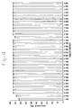
- test pieces which have been joined to one another by means of the friction stir welding method described above are shown in the chart in Fig. 4.
- Said sample comprises two plates 3, 4 attached to one another by means of the friction stir weld 13, which were then sawn into test pieces.
- Fig, 4 shows the results for a total of 32 test pieces, that is to say four test strips with eight samples from each. An ultimate tensile stress of approximately 450 MPa was determined for virtually all test pieces.
Landscapes
- Engineering & Computer Science (AREA)
- Mechanical Engineering (AREA)
- Pressure Welding/Diffusion-Bonding (AREA)
- Lining Or Joining Of Plastics Or The Like (AREA)
Abstract
- clamping the elements (3,4) such that the parts thereof which face one another and are to be joined are immovable with respect to one another,
- bringing a mandrel into contact with said parts in the region of the joint to be produced,
- cyclic movement of the mandrel (10) with respect to the elements (3,4) such that frictional heat is generated and the parts are brought into the plastic state,
- influencing the distribution of frictional heat in at least one of said elements such that the frictional heat is essentially concentrated in the parts of said at least one element which have been brought into the plastic state, and
- allowing the parts brought into the plastic state to cool in order to form the joint.
Description
- clamping the elements such that the parts thereof which face one another and are to be joined are immovable with respect to one another,
- bringing a mandrel into contact with said parts in the region of the joint to be produced,
- cyclic movement of the mandrel with respect to the elements such that frictional heat is generated and the parts are brought into the plastic state,
- influencing the distribution of frictional heat in at least one of said elements such that the frictional heat is essentially concentrated in the parts of said at least one element which have been brought into the plastic state, and
- allowing the parts brought into the plastic state to cool in order to form the joint.
Claims (12)
- Method for joining elements (3, 4) to one another by means of friction stir welding, comprising the following steps:clamping the elements (3, 4) such that the parts thereof which face one another and are to be joined are immovable with respect to one another.bringing a mandrel (9, 10) into contact with said parts in the region of the joint to be produced,cyclic movement of the mandrel (9, 10) with respect to the elements (3, 4) such that frictional heat is generated and the parts are brought into the plastic state,influencing the distribution of frictional heat in at least one of said elements (3, 4) such that the frictional heat is essentially concentrated in the parts of said at least one element (3, 4) which have been brought into the plastic state, andallowing the parts brought into the plastic state to cool in order to form the joint.
- Method according to Claim 1, comprising the step for bringing at least one element (3, 4) into contact with an insulator (2) which has a lower coefficient of thermal conductivity than that element (3, 4).
- Method according to Claim 2, comprising the step for bringing the major proportion of the surface of at least one element (3, 4) into contact with the insulator (2).
- Method according to Claim 1, 2 or 3, comprising the step for bringing at least one element (3, 4) into contact with a heat conductor (7, 8) which has at least the same coefficient of thermal conductivity as said element.
- Method according to one of the preceding claims, comprising the use of a rotary mandrel (9, 10), the speed of revolution of which is at most 600 revolutions per minute.
- Method according to Claim 5, comprising the use of a rotary mandrel (9, 10), the speed of rotation of which is in the range of 400 - 500 revolutions per minute.
- Method according to one of the preceding claims, comprising the use of a rotary mandrel (9, 10), the circumferential speed of which is at most 37 m/min.
- Method according to one of the preceding claims, comprising the use of a rotary mandrel (9, 10), the circumferential speed of which is in the range of 20 - 31 m/min.
- Method according to one of the preceding claims, comprising movement of the mandrel (9, 10) relative to the parts at a tracking speed of at least 400 mm/min.
- Method according to one of the preceding claims, comprising the use of a mandrel (9, 10) having an external surface made of ceramic material.
- Method according to Claim 10, comprising the use of a mandrel (9, 10) having an external surface made of zirconium oxide.
- Method according to Claim 10, comprising the use of a mandrel (9, 10) having an external surface made of aluminium oxide.
Applications Claiming Priority (2)
| Application Number | Priority Date | Filing Date | Title |
|---|---|---|---|
| NL1011908A NL1011908C1 (en) | 1999-04-27 | 1999-04-27 | Friction stir welding. |
| NL1011908 | 1999-04-27 |
Publications (3)
| Publication Number | Publication Date |
|---|---|
| EP1048390A2 true EP1048390A2 (en) | 2000-11-02 |
| EP1048390A3 EP1048390A3 (en) | 2001-11-14 |
| EP1048390B1 EP1048390B1 (en) | 2005-03-16 |
Family
ID=19769098
Family Applications (1)
| Application Number | Title | Priority Date | Filing Date |
|---|---|---|---|
| EP00201607A Expired - Lifetime EP1048390B1 (en) | 1999-04-27 | 2000-04-27 | Friction stir welding |
Country Status (6)
| Country | Link |
|---|---|
| US (1) | US6360937B1 (en) |
| EP (1) | EP1048390B1 (en) |
| AT (1) | ATE290937T1 (en) |
| DE (1) | DE60018632T2 (en) |
| ES (1) | ES2237383T3 (en) |
| NL (1) | NL1011908C1 (en) |
Cited By (20)
| Publication number | Priority date | Publication date | Assignee | Title |
|---|---|---|---|---|
| US6237829B1 (en) * | 1997-07-23 | 2001-05-29 | Hitachi, Ltd. | Friction stir welding apparatus |
| US6237835B1 (en) * | 2000-02-29 | 2001-05-29 | The Boeing Company | Method and apparatus for backing up a friction stir weld joint |
| WO2002078893A3 (en) * | 2001-03-29 | 2003-03-06 | Mazda Motor | Friction stir welding method and apparatus |
| US6648206B2 (en) | 2000-05-08 | 2003-11-18 | Tracey W. Nelson | Friction stir welding using a superabrasive tool |
| US6779708B2 (en) | 2002-12-13 | 2004-08-24 | The Boeing Company | Joining structural members by friction welding |
| US6910616B2 (en) | 2002-03-07 | 2005-06-28 | The Boeing Company | Preforms for forming machined structural assemblies |
| US7128948B2 (en) | 2003-10-20 | 2006-10-31 | The Boeing Company | Sprayed preforms for forming structural members |
| US7225968B2 (en) | 2003-08-04 | 2007-06-05 | Sii Megadiamond, Inc. | Crack repair using friction stir welding on materials including metal matrix composites, ferrous alloys, non-ferrous alloys, and superalloys |
| US7225967B2 (en) | 2003-12-16 | 2007-06-05 | The Boeing Company | Structural assemblies and preforms therefor formed by linear friction welding |
| US7270257B2 (en) | 2003-01-30 | 2007-09-18 | Sii Megadiamond, Inc. | Out-of-position friction stir welding of high melting temperature alloys |
| US7398911B2 (en) | 2003-12-16 | 2008-07-15 | The Boeing Company | Structural assemblies and preforms therefor formed by friction welding |
| US7530486B2 (en) | 2003-05-05 | 2009-05-12 | Sii Megadiamond, Inc. | Applications of friction stir welding using a superabrasive tool |
| US7608296B2 (en) | 2001-06-12 | 2009-10-27 | Brigham Young University | Anvil for friction stir welding high temperature materials |
| US7651018B2 (en) | 2004-10-05 | 2010-01-26 | Sii Megadiamond | Expandable mandrel for use in friction stir welding |
| EP2233238A1 (en) | 2009-03-26 | 2010-09-29 | Eurocopter | Method of friction stir welding between metallic workpieces, with control of welding temperature using a unique thermally conductive sheet |
| US8056797B2 (en) | 2005-10-05 | 2011-11-15 | Megastir Technologies | Expandable mandrel for use in friction stir welding |
| US8186561B2 (en) | 2004-03-24 | 2012-05-29 | Megastir Technologies, LLC | Solid state processing of hand-held knife blades to improve blade performance |
| US8550326B2 (en) | 2005-10-05 | 2013-10-08 | Megastir Technologies Llc | Expandable mandrel for use in friction stir welding |
| US8955734B2 (en) | 2004-05-21 | 2015-02-17 | Smith International, Inc. | Ball hole welding using the friction stir welding (FSW) process |
| EP3017905A1 (en) * | 2014-11-10 | 2016-05-11 | MAGNA STEYR Engineering AG & Co KG | Method for connecting two flat components |
Families Citing this family (27)
| Publication number | Priority date | Publication date | Assignee | Title |
|---|---|---|---|---|
| JP3400409B2 (en) * | 2000-04-28 | 2003-04-28 | マツダ株式会社 | Joining method and joining device |
| JP3864888B2 (en) * | 2002-10-28 | 2007-01-10 | マツダ株式会社 | Joining method using friction stir |
| US7367487B2 (en) * | 2003-08-22 | 2008-05-06 | Honda Motor Co., Ltd. | Method for friction stir welding, jig therefor, member with friction stir-welded portion, and tool for friction stir welding |
| US7121448B2 (en) * | 2003-08-29 | 2006-10-17 | General Electric Company | Friction stir welding apparatus and associated thermal management systems and methods |
| DE102005029882A1 (en) * | 2005-06-27 | 2006-12-28 | Gkss-Forschungszentrum Geesthacht Gmbh | Friction stir welding apparatus includes first inner segment surrounding a pin and having first friction surface segment surrounding the first inner segment and rotationally driven independently of the first inner segment |
| US20070057015A1 (en) * | 2005-09-09 | 2007-03-15 | Kevin Colligan | Tapered friction stir welding and processing tool |
| US20080041921A1 (en) * | 2005-09-26 | 2008-02-21 | Kevin Creehan | Friction stir fabrication |
| US9511446B2 (en) | 2014-12-17 | 2016-12-06 | Aeroprobe Corporation | In-situ interlocking of metals using additive friction stir processing |
| US9511445B2 (en) | 2014-12-17 | 2016-12-06 | Aeroprobe Corporation | Solid state joining using additive friction stir processing |
| US8875976B2 (en) | 2005-09-26 | 2014-11-04 | Aeroprobe Corporation | System for continuous feeding of filler material for friction stir welding, processing and fabrication |
| US9266191B2 (en) | 2013-12-18 | 2016-02-23 | Aeroprobe Corporation | Fabrication of monolithic stiffening ribs on metallic sheets |
| US8632850B2 (en) | 2005-09-26 | 2014-01-21 | Schultz-Creehan Holdings, Inc. | Friction fabrication tools |
| US8397974B2 (en) | 2005-09-26 | 2013-03-19 | Aeroprobe Corporation | Self-reacting friction stir welding tool with the ability to add filler material |
| JP4586698B2 (en) * | 2005-09-29 | 2010-11-24 | マツダ株式会社 | Friction spot welding device |
| US20080099533A1 (en) * | 2006-10-31 | 2008-05-01 | General Electric | Method for controlling microstructure via thermally managed solid state joining |
| JP5094140B2 (en) * | 2006-11-09 | 2012-12-12 | 日野自動車株式会社 | Member joint structure |
| JP4972417B2 (en) * | 2006-12-15 | 2012-07-11 | 日野自動車株式会社 | Member joining method and structure |
| US8164021B1 (en) * | 2008-03-31 | 2012-04-24 | The United States Of America As Represented By The Secretary Of The Navy | Electrically assisted friction stir welding |
| CA2779075C (en) | 2009-11-02 | 2016-05-10 | Megastir Technologies Llc | Out of position friction stir welding of casing and small diameter tubing or pipe |
| DE102010032402A1 (en) * | 2010-07-27 | 2012-02-02 | Airbus Operations Gmbh | Method of joining two aircraft body segments by means of friction stir welding |
| EP2844415B1 (en) * | 2012-04-30 | 2016-08-03 | Université Catholique de Louvain | Method for welding at least two layers |
| US8678268B1 (en) | 2012-11-21 | 2014-03-25 | Fluor Technologies Corporation | Friction stir welding using a sacrificial anvil |
| JP6503631B2 (en) * | 2014-04-02 | 2019-04-24 | 株式会社Ihi | Work fixing device for friction stir welding device |
| EP3500390A1 (en) * | 2016-08-22 | 2019-06-26 | Novelis, Inc. | Components and systems for friction stir welding and related processes |
| JP7089034B2 (en) | 2017-10-31 | 2022-06-21 | メルド マニファクチャリング コーポレーション | Solid-state laminated modeling system as well as material composition and structural background |
| JP7452496B2 (en) * | 2021-06-07 | 2024-03-19 | 日本軽金属株式会社 | Bonded body manufacturing method and bonding device |
| US20240293890A1 (en) * | 2021-09-17 | 2024-09-05 | Abb Schweiz Ag | Pressing device for fixing workpiece onto worktable |
Family Cites Families (19)
| Publication number | Priority date | Publication date | Assignee | Title |
|---|---|---|---|---|
| GB572789A (en) | 1941-10-17 | 1945-10-24 | Hans Klopstock | An improved method of joining or welding metals |
| DE2102020A1 (en) | 1971-01-16 | 1972-09-21 | Luc J | Adhesive processes, facilities for carrying out the process and application of the process |
| JPS601118B2 (en) | 1981-03-10 | 1985-01-11 | 川崎重工業株式会社 | Friction welding method |
| JPS61176484A (en) | 1985-01-31 | 1986-08-08 | Ishikawajima Harima Heavy Ind Co Ltd | Joining method of metallic plate |
| SU1362593A2 (en) | 1986-08-04 | 1987-12-30 | Днепропетровский Трубопрокатный Завод Им.В.И.Ленина | Method of producing longitudinal welded tubes |
| SU1433522A1 (en) | 1987-03-09 | 1988-10-30 | Днепропетровский Металлургический Институт Им.Л.И.Брежнева | Apparatus for friction of longitudinal welding tubes |
| GB9125978D0 (en) * | 1991-12-06 | 1992-02-05 | Welding Inst | Hot shear butt welding |
| NO942790D0 (en) | 1994-03-28 | 1994-07-27 | Norsk Hydro As | Method of friction welding and device for the same |
| DE4431989A1 (en) * | 1994-09-08 | 1996-03-14 | Opel Adam Ag | Welding machine for joining two thin metal sheets |
| US6102636A (en) * | 1996-05-21 | 2000-08-15 | Geise; Samuel C. | Hydraulically powered spindle for working metals and composite materials |
| US6516992B1 (en) * | 1996-05-31 | 2003-02-11 | The Boeing Company | Friction stir welding with simultaneous cooling |
| US5794835A (en) * | 1996-05-31 | 1998-08-18 | The Boeing Company | Friction stir welding |
| US5829664A (en) * | 1996-11-15 | 1998-11-03 | Aluminum Company Of America | Resistance heated stir welding |
| GB9625394D0 (en) * | 1996-12-06 | 1997-01-22 | Lead Sheet Ass | Mobile friction welding apparatus |
| JP3598204B2 (en) * | 1997-06-26 | 2004-12-08 | 昭和電工株式会社 | Friction stir welding method and friction stir welding device |
| US5975406A (en) * | 1998-02-27 | 1999-11-02 | The Boeing Company | Method to repair voids in aluminum alloys |
| US6070784A (en) * | 1998-07-08 | 2000-06-06 | The Boeing Company | Contact backup roller approach to FSW process |
| US6045028A (en) * | 1998-07-17 | 2000-04-04 | Mcdonnell Douglas Corporation | Integral corrosion protection of friction-welded joints |
| US6168066B1 (en) * | 1999-04-21 | 2001-01-02 | Lockheed Martin Corp. | Friction stir conduction controller |
-
1999
- 1999-04-27 NL NL1011908A patent/NL1011908C1/en not_active IP Right Cessation
-
2000
- 2000-04-27 ES ES00201607T patent/ES2237383T3/en not_active Expired - Lifetime
- 2000-04-27 AT AT00201607T patent/ATE290937T1/en not_active IP Right Cessation
- 2000-04-27 DE DE60018632T patent/DE60018632T2/en not_active Expired - Fee Related
- 2000-04-27 US US09/559,487 patent/US6360937B1/en not_active Expired - Fee Related
- 2000-04-27 EP EP00201607A patent/EP1048390B1/en not_active Expired - Lifetime
Cited By (44)
| Publication number | Priority date | Publication date | Assignee | Title |
|---|---|---|---|---|
| US6613447B2 (en) | 1997-07-23 | 2003-09-02 | Kinya Aota | Structural body formed by friction stir welding and having protrusion at the weld provided prior to the welding |
| US6716538B2 (en) | 1997-07-23 | 2004-04-06 | Hitachi, Ltd. | Structural body formed by friction stir welding |
| US6378754B2 (en) | 1997-07-23 | 2002-04-30 | Hitachi, Ltd. | Friction stir welding method including removal of protruding portion, and structural body formed thereby |
| US6619534B2 (en) | 1997-07-23 | 2003-09-16 | Hitachi, Ltd. | Friction stir welding method using members which overlap and have protrusion at the weld location prior to the welding |
| US6419144B2 (en) | 1997-07-23 | 2002-07-16 | Hitachi, Ltd. | Method of forming structural body using friction stir welding, and structural body formed |
| US6237829B1 (en) * | 1997-07-23 | 2001-05-29 | Hitachi, Ltd. | Friction stir welding apparatus |
| US6585443B2 (en) | 1997-07-23 | 2003-07-01 | Hitachi, Ltd. | Structural body formed by friction stir welding two members, one of which has a protruding portion |
| US6607837B2 (en) | 1997-07-23 | 2003-08-19 | Hitachi, Ltd. | Structural body formed by friction stir welding method |
| US6936332B2 (en) | 1997-07-23 | 2005-08-30 | Hitachi, Ltd. | Extruded frame member for use in friction stir welding |
| US6382498B2 (en) | 1997-07-23 | 2002-05-07 | Hitachi, Ltd. | Friction stir welding method including positioning of rotary tool, and structural body formed thereby |
| US6237835B1 (en) * | 2000-02-29 | 2001-05-29 | The Boeing Company | Method and apparatus for backing up a friction stir weld joint |
| US6648206B2 (en) | 2000-05-08 | 2003-11-18 | Tracey W. Nelson | Friction stir welding using a superabrasive tool |
| US6779704B2 (en) | 2000-05-08 | 2004-08-24 | Tracy W. Nelson | Friction stir welding of metal matrix composites, ferrous alloys, non-ferrous alloys, and superalloys using a superabrasive tool |
| US8302834B2 (en) | 2000-05-08 | 2012-11-06 | MegaStar Technologies LLC | Friction stir welding using a superabrasive tool |
| US7993575B2 (en) | 2000-05-08 | 2011-08-09 | Megastir Technologies, LLC | Friction stir welding using a superabrasive tool |
| US9061370B2 (en) | 2000-05-08 | 2015-06-23 | Brigham Young University | Friction stir welding using a superabrasive tool |
| US7152776B2 (en) | 2000-05-08 | 2006-12-26 | Sii Megadiamond, Inc. | Friction stir welding using a superabrasive tool |
| US7661572B2 (en) | 2000-05-08 | 2010-02-16 | Brigham Young University | Friction stir welding using a superabrasive tool |
| US7124929B2 (en) | 2000-05-08 | 2006-10-24 | Sii Megadiamond, Inc. | Friction stir welding of metal matrix composites, ferrous alloys, non-ferrous alloys, and superalloys using a superabrasive tool |
| US6789722B2 (en) | 2001-03-29 | 2004-09-14 | Mazda Motor Corporation | Joining method and apparatus using frictional agitation |
| WO2002078893A3 (en) * | 2001-03-29 | 2003-03-06 | Mazda Motor | Friction stir welding method and apparatus |
| US7608296B2 (en) | 2001-06-12 | 2009-10-27 | Brigham Young University | Anvil for friction stir welding high temperature materials |
| US6910616B2 (en) | 2002-03-07 | 2005-06-28 | The Boeing Company | Preforms for forming machined structural assemblies |
| US7083076B2 (en) | 2002-12-13 | 2006-08-01 | The Boeing Company | Joining structural members by friction welding |
| US7431194B2 (en) | 2002-12-13 | 2008-10-07 | The Boeing Company | Joining structural members by friction welding |
| US6779708B2 (en) | 2002-12-13 | 2004-08-24 | The Boeing Company | Joining structural members by friction welding |
| US7270257B2 (en) | 2003-01-30 | 2007-09-18 | Sii Megadiamond, Inc. | Out-of-position friction stir welding of high melting temperature alloys |
| US7530486B2 (en) | 2003-05-05 | 2009-05-12 | Sii Megadiamond, Inc. | Applications of friction stir welding using a superabrasive tool |
| US7225968B2 (en) | 2003-08-04 | 2007-06-05 | Sii Megadiamond, Inc. | Crack repair using friction stir welding on materials including metal matrix composites, ferrous alloys, non-ferrous alloys, and superalloys |
| US7128948B2 (en) | 2003-10-20 | 2006-10-31 | The Boeing Company | Sprayed preforms for forming structural members |
| US7381446B2 (en) | 2003-10-20 | 2008-06-03 | The Boeing Company | Sprayed preforms to forming structural members |
| US7225967B2 (en) | 2003-12-16 | 2007-06-05 | The Boeing Company | Structural assemblies and preforms therefor formed by linear friction welding |
| US7854363B2 (en) | 2003-12-16 | 2010-12-21 | The Boeing Company | Structural assemblies and preforms therefor formed by friction welding |
| US7669750B2 (en) | 2003-12-16 | 2010-03-02 | The Boeing Company | Method for forming a preform for a structural assembly |
| US8506201B2 (en) | 2003-12-16 | 2013-08-13 | The Boeing Company | Structural assemblies and preforms therefor formed by linear friction welding |
| US7398911B2 (en) | 2003-12-16 | 2008-07-15 | The Boeing Company | Structural assemblies and preforms therefor formed by friction welding |
| US8186561B2 (en) | 2004-03-24 | 2012-05-29 | Megastir Technologies, LLC | Solid state processing of hand-held knife blades to improve blade performance |
| US8955734B2 (en) | 2004-05-21 | 2015-02-17 | Smith International, Inc. | Ball hole welding using the friction stir welding (FSW) process |
| US7651018B2 (en) | 2004-10-05 | 2010-01-26 | Sii Megadiamond | Expandable mandrel for use in friction stir welding |
| US8056797B2 (en) | 2005-10-05 | 2011-11-15 | Megastir Technologies | Expandable mandrel for use in friction stir welding |
| US8550326B2 (en) | 2005-10-05 | 2013-10-08 | Megastir Technologies Llc | Expandable mandrel for use in friction stir welding |
| EP2233238A1 (en) | 2009-03-26 | 2010-09-29 | Eurocopter | Method of friction stir welding between metallic workpieces, with control of welding temperature using a unique thermally conductive sheet |
| US8393519B2 (en) | 2009-03-26 | 2013-03-12 | Eurocopter | Method of assembling metal parts by friction welding, with the welding temperature being controlled using thermally conductive elements |
| EP3017905A1 (en) * | 2014-11-10 | 2016-05-11 | MAGNA STEYR Engineering AG & Co KG | Method for connecting two flat components |
Also Published As
| Publication number | Publication date |
|---|---|
| DE60018632D1 (en) | 2005-04-21 |
| US6360937B1 (en) | 2002-03-26 |
| DE60018632T2 (en) | 2006-03-16 |
| EP1048390B1 (en) | 2005-03-16 |
| EP1048390A3 (en) | 2001-11-14 |
| ES2237383T3 (en) | 2005-08-01 |
| NL1011908C1 (en) | 2000-10-30 |
| ATE290937T1 (en) | 2005-04-15 |
Similar Documents
| Publication | Publication Date | Title |
|---|---|---|
| EP1048390B1 (en) | Friction stir welding | |
| US7431194B2 (en) | Joining structural members by friction welding | |
| EP1077787B1 (en) | Friction stir welding tool | |
| JP3619818B2 (en) | Friction stir weld joint strengthening method, structural assembly and manufacturing method thereof | |
| US7762447B2 (en) | Multiple pass and multiple layer friction stir welding and material enhancement processes | |
| AU2009200386B2 (en) | Device to join the faces of parts | |
| US7854363B2 (en) | Structural assemblies and preforms therefor formed by friction welding | |
| US20050127140A1 (en) | Structural assemblies and preforms therefor formed by linear friction welding | |
| US20200384569A1 (en) | Joining process for neutron absorbing materials | |
| CN110860784B (en) | Friction stir welding method for preparing bulk high-entropy alloy | |
| CZ294721B6 (en) | Method and apparatus for friction stir welding | |
| US3823299A (en) | Metallurgical bonding and forming processes and apparatus | |
| US3749298A (en) | Apparatus for friction welding | |
| JP4328622B2 (en) | Method and apparatus for joining light metal parts | |
| Yilbas et al. | Investigation into the properties of friction-welded aluminium bars | |
| US3851138A (en) | Diffusion bonding of butt joints | |
| JPH09512748A (en) | Method and apparatus for welding thin sheets | |
| US6641028B2 (en) | Friction filler welding | |
| AGHAJANI et al. | Effects of friction stir welding tool plunge depth on microstructure and texture evolution of AA1100 to A441 AISI joint | |
| Kim et al. | A feasibility study on the three-dimensional friction stir welding of aluminum 5083-O thin plate | |
| JP4346282B2 (en) | Metal plate joined by friction welding, metal plate joining method by friction welding, and metal plate joining apparatus by friction welding | |
| JP2520245B2 (en) | Joining method for dissimilar metal materials | |
| Kamat et al. | An experimental investigation of mechanical properties of Al 6106 T6 alloy joined by Friction Stir Welding and TIG welding | |
| JPS62289376A (en) | Joining method for al or al base alloy and al base composite material | |
| Rossini et al. | Low Carbon Steel Plate Welding Using a CO 2 Laser Equipment |
Legal Events
| Date | Code | Title | Description |
|---|---|---|---|
| PUAI | Public reference made under article 153(3) epc to a published international application that has entered the european phase |
Free format text: ORIGINAL CODE: 0009012 |
|
| AK | Designated contracting states |
Kind code of ref document: A2 Designated state(s): AT BE CH CY DE DK ES FI FR GB GR IE IT LI LU MC NL PT SE |
|
| AX | Request for extension of the european patent |
Free format text: AL;LT;LV;MK;RO;SI |
|
| PUAL | Search report despatched |
Free format text: ORIGINAL CODE: 0009013 |
|
| AK | Designated contracting states |
Kind code of ref document: A3 Designated state(s): AT BE CH CY DE DK ES FI FR GB GR IE IT LI LU MC NL PT SE |
|
| AX | Request for extension of the european patent |
Free format text: AL;LT;LV;MK;RO;SI |
|
| 17P | Request for examination filed |
Effective date: 20020514 |
|
| AKX | Designation fees paid |
Free format text: AT BE CH CY DE DK ES FI FR GB GR IE IT LI LU MC NL PT SE |
|
| 17Q | First examination report despatched |
Effective date: 20031128 |
|
| GRAP | Despatch of communication of intention to grant a patent |
Free format text: ORIGINAL CODE: EPIDOSNIGR1 |
|
| GRAS | Grant fee paid |
Free format text: ORIGINAL CODE: EPIDOSNIGR3 |
|
| GRAA | (expected) grant |
Free format text: ORIGINAL CODE: 0009210 |
|
| AK | Designated contracting states |
Kind code of ref document: B1 Designated state(s): AT BE CH CY DE DK ES FI FR GB GR IE IT LI LU MC NL PT SE |
|
| PG25 | Lapsed in a contracting state [announced via postgrant information from national office to epo] |
Ref country code: AT Free format text: LAPSE BECAUSE OF FAILURE TO SUBMIT A TRANSLATION OF THE DESCRIPTION OR TO PAY THE FEE WITHIN THE PRESCRIBED TIME-LIMIT Effective date: 20050316 Ref country code: CH Free format text: LAPSE BECAUSE OF FAILURE TO SUBMIT A TRANSLATION OF THE DESCRIPTION OR TO PAY THE FEE WITHIN THE PRESCRIBED TIME-LIMIT Effective date: 20050316 Ref country code: LI Free format text: LAPSE BECAUSE OF FAILURE TO SUBMIT A TRANSLATION OF THE DESCRIPTION OR TO PAY THE FEE WITHIN THE PRESCRIBED TIME-LIMIT Effective date: 20050316 Ref country code: FI Free format text: LAPSE BECAUSE OF FAILURE TO SUBMIT A TRANSLATION OF THE DESCRIPTION OR TO PAY THE FEE WITHIN THE PRESCRIBED TIME-LIMIT Effective date: 20050316 |
|
| REG | Reference to a national code |
Ref country code: GB Ref legal event code: FG4D |
|
| REG | Reference to a national code |
Ref country code: CH Ref legal event code: EP |
|
| REG | Reference to a national code |
Ref country code: IE Ref legal event code: FG4D |
|
| REF | Corresponds to: |
Ref document number: 60018632 Country of ref document: DE Date of ref document: 20050421 Kind code of ref document: P |
|
| PG25 | Lapsed in a contracting state [announced via postgrant information from national office to epo] |
Ref country code: LU Free format text: LAPSE BECAUSE OF NON-PAYMENT OF DUE FEES Effective date: 20050427 Ref country code: CY Free format text: LAPSE BECAUSE OF FAILURE TO SUBMIT A TRANSLATION OF THE DESCRIPTION OR TO PAY THE FEE WITHIN THE PRESCRIBED TIME-LIMIT Effective date: 20050427 Ref country code: IE Free format text: LAPSE BECAUSE OF NON-PAYMENT OF DUE FEES Effective date: 20050427 |
|
| PG25 | Lapsed in a contracting state [announced via postgrant information from national office to epo] |
Ref country code: MC Free format text: LAPSE BECAUSE OF NON-PAYMENT OF DUE FEES Effective date: 20050430 |
|
| RAP2 | Party data changed (patent owner data changed or rights of a patent transferred) |
Owner name: STORK FOKKER AESP B.V. |
|
| REG | Reference to a national code |
Ref country code: SE Ref legal event code: TRGR |
|
| PG25 | Lapsed in a contracting state [announced via postgrant information from national office to epo] |
Ref country code: GR Free format text: LAPSE BECAUSE OF FAILURE TO SUBMIT A TRANSLATION OF THE DESCRIPTION OR TO PAY THE FEE WITHIN THE PRESCRIBED TIME-LIMIT Effective date: 20050616 Ref country code: DK Free format text: LAPSE BECAUSE OF FAILURE TO SUBMIT A TRANSLATION OF THE DESCRIPTION OR TO PAY THE FEE WITHIN THE PRESCRIBED TIME-LIMIT Effective date: 20050616 |
|
| NLT2 | Nl: modifications (of names), taken from the european patent patent bulletin |
Owner name: STORK FOKKER AESP B.V. |
|
| REG | Reference to a national code |
Ref country code: ES Ref legal event code: FG2A Ref document number: 2237383 Country of ref document: ES Kind code of ref document: T3 |
|
| PG25 | Lapsed in a contracting state [announced via postgrant information from national office to epo] |
Ref country code: PT Free format text: LAPSE BECAUSE OF FAILURE TO SUBMIT A TRANSLATION OF THE DESCRIPTION OR TO PAY THE FEE WITHIN THE PRESCRIBED TIME-LIMIT Effective date: 20050907 |
|
| REG | Reference to a national code |
Ref country code: CH Ref legal event code: PL |
|
| REG | Reference to a national code |
Ref country code: FR Ref legal event code: CD |
|
| ET | Fr: translation filed | ||
| PLBE | No opposition filed within time limit |
Free format text: ORIGINAL CODE: 0009261 |
|
| STAA | Information on the status of an ep patent application or granted ep patent |
Free format text: STATUS: NO OPPOSITION FILED WITHIN TIME LIMIT |
|
| 26N | No opposition filed |
Effective date: 20051219 |
|
| NLXE | Nl: other communications concerning ep-patents (part 3 heading xe) |
Free format text: PAT. BUL. 09/2005 CORR.: STORK FOKKER AESP B.V. |
|
| PGFP | Annual fee paid to national office [announced via postgrant information from national office to epo] |
Ref country code: ES Payment date: 20090424 Year of fee payment: 10 |
|
| PGFP | Annual fee paid to national office [announced via postgrant information from national office to epo] |
Ref country code: NL Payment date: 20090424 Year of fee payment: 10 Ref country code: SE Payment date: 20090420 Year of fee payment: 10 Ref country code: IT Payment date: 20090430 Year of fee payment: 10 Ref country code: FR Payment date: 20090423 Year of fee payment: 10 Ref country code: DE Payment date: 20090422 Year of fee payment: 10 |
|
| PGFP | Annual fee paid to national office [announced via postgrant information from national office to epo] |
Ref country code: BE Payment date: 20090428 Year of fee payment: 10 |
|
| PGFP | Annual fee paid to national office [announced via postgrant information from national office to epo] |
Ref country code: GB Payment date: 20090424 Year of fee payment: 10 |
|
| BERE | Be: lapsed |
Owner name: *STORK FOKKER AESP B.V. Effective date: 20100430 |
|
| REG | Reference to a national code |
Ref country code: NL Ref legal event code: V1 Effective date: 20101101 |
|
| EUG | Se: european patent has lapsed | ||
| GBPC | Gb: european patent ceased through non-payment of renewal fee |
Effective date: 20100427 |
|
| REG | Reference to a national code |
Ref country code: FR Ref legal event code: ST Effective date: 20101230 |
|
| PG25 | Lapsed in a contracting state [announced via postgrant information from national office to epo] |
Ref country code: NL Free format text: LAPSE BECAUSE OF NON-PAYMENT OF DUE FEES Effective date: 20101101 |
|
| PG25 | Lapsed in a contracting state [announced via postgrant information from national office to epo] |
Ref country code: DE Free format text: LAPSE BECAUSE OF NON-PAYMENT OF DUE FEES Effective date: 20101103 |
|
| PG25 | Lapsed in a contracting state [announced via postgrant information from national office to epo] |
Ref country code: IT Free format text: LAPSE BECAUSE OF NON-PAYMENT OF DUE FEES Effective date: 20100427 Ref country code: GB Free format text: LAPSE BECAUSE OF NON-PAYMENT OF DUE FEES Effective date: 20100427 Ref country code: BE Free format text: LAPSE BECAUSE OF NON-PAYMENT OF DUE FEES Effective date: 20100430 |
|
| REG | Reference to a national code |
Ref country code: ES Ref legal event code: FD2A Effective date: 20110715 |
|
| PG25 | Lapsed in a contracting state [announced via postgrant information from national office to epo] |
Ref country code: ES Free format text: LAPSE BECAUSE OF NON-PAYMENT OF DUE FEES Effective date: 20110705 |
|
| PG25 | Lapsed in a contracting state [announced via postgrant information from national office to epo] |
Ref country code: ES Free format text: LAPSE BECAUSE OF NON-PAYMENT OF DUE FEES Effective date: 20100428 |
|
| PG25 | Lapsed in a contracting state [announced via postgrant information from national office to epo] |
Ref country code: FR Free format text: LAPSE BECAUSE OF NON-PAYMENT OF DUE FEES Effective date: 20100430 |
|
| PG25 | Lapsed in a contracting state [announced via postgrant information from national office to epo] |
Ref country code: SE Free format text: LAPSE BECAUSE OF NON-PAYMENT OF DUE FEES Effective date: 20100428 |