EP1047545B1 - Cushioning conversion machine and method - Google Patents
Cushioning conversion machine and method Download PDFInfo
- Publication number
- EP1047545B1 EP1047545B1 EP99902198A EP99902198A EP1047545B1 EP 1047545 B1 EP1047545 B1 EP 1047545B1 EP 99902198 A EP99902198 A EP 99902198A EP 99902198 A EP99902198 A EP 99902198A EP 1047545 B1 EP1047545 B1 EP 1047545B1
- Authority
- EP
- European Patent Office
- Prior art keywords
- stock material
- stock
- ply
- assembly
- portions
- Prior art date
- Legal status (The legal status is an assumption and is not a legal conclusion. Google has not performed a legal analysis and makes no representation as to the accuracy of the status listed.)
- Expired - Lifetime
Links
Images


Classifications
-
- B—PERFORMING OPERATIONS; TRANSPORTING
- B31—MAKING ARTICLES OF PAPER, CARDBOARD OR MATERIAL WORKED IN A MANNER ANALOGOUS TO PAPER; WORKING PAPER, CARDBOARD OR MATERIAL WORKED IN A MANNER ANALOGOUS TO PAPER
- B31D—MAKING ARTICLES OF PAPER, CARDBOARD OR MATERIAL WORKED IN A MANNER ANALOGOUS TO PAPER, NOT PROVIDED FOR IN SUBCLASSES B31B OR B31C
- B31D5/00—Multiple-step processes for making three-dimensional articles ; Making three-dimensional articles
- B31D5/0039—Multiple-step processes for making three-dimensional articles ; Making three-dimensional articles for making dunnage or cushion pads
- B31D5/0043—Multiple-step processes for making three-dimensional articles ; Making three-dimensional articles for making dunnage or cushion pads including crumpling flat material
- B31D5/0047—Multiple-step processes for making three-dimensional articles ; Making three-dimensional articles for making dunnage or cushion pads including crumpling flat material involving toothed wheels
-
- C—CHEMISTRY; METALLURGY
- C09—DYES; PAINTS; POLISHES; NATURAL RESINS; ADHESIVES; COMPOSITIONS NOT OTHERWISE PROVIDED FOR; APPLICATIONS OF MATERIALS NOT OTHERWISE PROVIDED FOR
- C09D—COATING COMPOSITIONS, e.g. PAINTS, VARNISHES OR LACQUERS; FILLING PASTES; CHEMICAL PAINT OR INK REMOVERS; INKS; CORRECTING FLUIDS; WOODSTAINS; PASTES OR SOLIDS FOR COLOURING OR PRINTING; USE OF MATERIALS THEREFOR
- C09D119/00—Coating compositions based on rubbers, not provided for in groups C09D107/00 - C09D117/00
- C09D119/003—Precrosslinked rubber; Scrap rubber; Used vulcanised rubber
-
- C—CHEMISTRY; METALLURGY
- C09—DYES; PAINTS; POLISHES; NATURAL RESINS; ADHESIVES; COMPOSITIONS NOT OTHERWISE PROVIDED FOR; APPLICATIONS OF MATERIALS NOT OTHERWISE PROVIDED FOR
- C09D—COATING COMPOSITIONS, e.g. PAINTS, VARNISHES OR LACQUERS; FILLING PASTES; CHEMICAL PAINT OR INK REMOVERS; INKS; CORRECTING FLUIDS; WOODSTAINS; PASTES OR SOLIDS FOR COLOURING OR PRINTING; USE OF MATERIALS THEREFOR
- C09D163/00—Coating compositions based on epoxy resins; Coating compositions based on derivatives of epoxy resins
-
- B—PERFORMING OPERATIONS; TRANSPORTING
- B31—MAKING ARTICLES OF PAPER, CARDBOARD OR MATERIAL WORKED IN A MANNER ANALOGOUS TO PAPER; WORKING PAPER, CARDBOARD OR MATERIAL WORKED IN A MANNER ANALOGOUS TO PAPER
- B31D—MAKING ARTICLES OF PAPER, CARDBOARD OR MATERIAL WORKED IN A MANNER ANALOGOUS TO PAPER, NOT PROVIDED FOR IN SUBCLASSES B31B OR B31C
- B31D2205/00—Multiple-step processes for making three-dimensional articles
- B31D2205/0005—Multiple-step processes for making three-dimensional articles for making dunnage or cushion pads
- B31D2205/0011—Multiple-step processes for making three-dimensional articles for making dunnage or cushion pads including particular additional operations
- B31D2205/0017—Providing stock material in a particular form
- B31D2205/0023—Providing stock material in a particular form as web from a roll
-
- B—PERFORMING OPERATIONS; TRANSPORTING
- B31—MAKING ARTICLES OF PAPER, CARDBOARD OR MATERIAL WORKED IN A MANNER ANALOGOUS TO PAPER; WORKING PAPER, CARDBOARD OR MATERIAL WORKED IN A MANNER ANALOGOUS TO PAPER
- B31D—MAKING ARTICLES OF PAPER, CARDBOARD OR MATERIAL WORKED IN A MANNER ANALOGOUS TO PAPER, NOT PROVIDED FOR IN SUBCLASSES B31B OR B31C
- B31D2205/00—Multiple-step processes for making three-dimensional articles
- B31D2205/0005—Multiple-step processes for making three-dimensional articles for making dunnage or cushion pads
- B31D2205/0011—Multiple-step processes for making three-dimensional articles for making dunnage or cushion pads including particular additional operations
- B31D2205/0047—Feeding, guiding or shaping the material
-
- B—PERFORMING OPERATIONS; TRANSPORTING
- B31—MAKING ARTICLES OF PAPER, CARDBOARD OR MATERIAL WORKED IN A MANNER ANALOGOUS TO PAPER; WORKING PAPER, CARDBOARD OR MATERIAL WORKED IN A MANNER ANALOGOUS TO PAPER
- B31D—MAKING ARTICLES OF PAPER, CARDBOARD OR MATERIAL WORKED IN A MANNER ANALOGOUS TO PAPER, NOT PROVIDED FOR IN SUBCLASSES B31B OR B31C
- B31D2205/00—Multiple-step processes for making three-dimensional articles
- B31D2205/0005—Multiple-step processes for making three-dimensional articles for making dunnage or cushion pads
- B31D2205/0076—Multiple-step processes for making three-dimensional articles for making dunnage or cushion pads involving particular machinery details
- B31D2205/0082—General layout of the machinery or relative arrangement of its subunits
-
- Y—GENERAL TAGGING OF NEW TECHNOLOGICAL DEVELOPMENTS; GENERAL TAGGING OF CROSS-SECTIONAL TECHNOLOGIES SPANNING OVER SEVERAL SECTIONS OF THE IPC; TECHNICAL SUBJECTS COVERED BY FORMER USPC CROSS-REFERENCE ART COLLECTIONS [XRACs] AND DIGESTS
- Y10—TECHNICAL SUBJECTS COVERED BY FORMER USPC
- Y10S—TECHNICAL SUBJECTS COVERED BY FORMER USPC CROSS-REFERENCE ART COLLECTIONS [XRACs] AND DIGESTS
- Y10S493/00—Manufacturing container or tube from paper; or other manufacturing from a sheet or web
- Y10S493/967—Dunnage, wadding, stuffing, or filling excelsior
Definitions
- the present invention relates generally as indicated to a cushioning conversion machine and method. More particularly, the present invention relates to a separator device, a constant-entry device, and/or a shaping member for use in a cushioning conversion machine or method.
- a protective packaging material is typically placed in the shipping case, or box, to fill any voids and/or to cushion the item during the shipping process.
- Some conventional commonly used protective packaging materials are plastic foam peanuts and plastic bubble pack. While these conventional plastic materials seem to adequately perform as cushioning products, they are not without disadvantages. Perhaps the most serious drawback of plastic bubble wrap and/or plastic foam peanuts is their effect on our environment. Quite simply, these plastic packaging materials are not biodegradable and thus they cannot avoid further multiplying our planet's already critical waste disposal problems. The non-biodegradability of these packaging materials has become increasingly important in light of many industries adopting more progressive policies in terms of environmental responsibility.
- paper protective packaging material a very popular alternative. Paper is biodegradable, recyclable and renewable; making it an environmentally responsible choice for conscientious industries. While paper in sheet form could possibly be used as a protective packaging material, it is usually preferable to convert the sheets of paper into a relatively low density pad-like cushioning dunnage product. This conversion may be accomplished by a cushioning conversion machine, such as that disclosed in U.S. Patent No. 5,322,477. This patent is assigned to the assignee of the present application and its entire disclosure is hereby incorporated herein by reference.
- the cushioning conversion machine disclosed in U.S. Patent No. 5,322,477 comprises a conversion assembly which converts multi-ply stock material into a three-dimensional cushioning product and a stock supply assembly which supplies the multi-ply stock material to the conversion assembly.
- the conversion assembly includes the forming assembly which inwardly turns the lateral regions of the stock material as it travels downstream therethrough. This inward turning results the lateral regions of the stock experiencing edge tension which sometimes results in ripping or tearing of the stock material.
- a need remains for further improvements to prevent excessive edge tension and/or the tearing associated therewith. This need is especially critical for the conversion of lesser quality and/or short fiber paper. Additionally or alternatively, a need remains for other improvements to the cushioning conversion machine to work in conjunction with tension-distributing devices or otherwise improve or enhance the conversion process.
- US patent number 3 799 039 discloses a cushioning dunnage producing mechanism which is of compact nature utilising a single role of stock material comprising multiples of sheetlike material, such as paper stock, which are separated as they are pulled off the composite roll, rolled or urged inwardly at their lateral edges and into generally superimposed condition and passed into a crumpler section where meshed gears coin or stitch the confronting portions of the rolled edges of the stock material together generally centrally in a direction lengthwise thereof, to hold the dunnage product in a lightweight, highly compressible, padlike configuration.
- the present invention provides a stock supply arrangement which prevents the stock material from abruptly experiencing inward turning just downstream of the stock supply assembly, or more particularly the separating device.
- the stock supply arrangement of the present invention allows a more gradual transition between the supply of the stock material to the conversion assembly and the inward turning of lateral regions of the stock material by the conversion assembly. Such a gradual transition is believed to reduce edge-tension in the stock material and/or otherwise enhance the conversion process.
- the present invention provides a cushioning conversion machine comprising a conversion assembly which converts a multi-ply stock material into a three dimensional cushioning product and a stock supply assembly which supplies the multi-ply stock material to the conversion assembly.
- the conversion assembly includes a forming assembly which inwardly turns lateral regions of the stock material as the stock material travels therethrough in a downstream direction.
- the forming assembly comprises a chute and a shaping member positioned at least partially within the chute with the stock material passing through the chute and around the shaping member as it travels through the forming assembly.
- the stock supply assembly may include a stock-dispensing device which dispenses the muiti-ply stock material from a continuous sheet or roll thereof and a separating device which separates the plies of the dispensed stock material upstream of the forming assembly.
- the separating device may include a plurality of transversely extending separating members which are positioned to engage respective plies of the multi-ply stock material. At least some of the separating members (and preferably all) are shaped to permit an initial inward turning of the lateral regions of the stock material in the same direction as the forming assembly. In this manner, there is a more gradual transition between the supply of the stock material to the machine's conversion assembly and the inward turning of lateral regions by the conversion assembly.
- the preferred separating members are shaped such that tension is substantially evenly distributed throughout the full width of the stock material. At least some (and preferably all) of the separating members have a bowed or curved configuration and thus do not follow a transverse linear path perpendicular to the upstream-downstream direction.
- the direction of concavity of the bowed separating members corresponds to the direction which the lateral regions of the stock material are inwardly turned.
- the magnitude of concavity of the bowed separating members is such that there will be a gradual transition between the curvature of the stock material from the separating device to the forming assembly.
- the stock supply assembly is adapted to supply stock material which is between 25 to 35 inches wide and more preferably between 27 and 30 inches wide.
- the conversion assembly converts this stock material into a cushioning product which is approximately 8 to 9 inches wide.
- the radii of curvature of the bowed separating members is preferably between 26 and 34 inches, more preferably between 27 and 33 inches, and even more preferably between 28 and 32 inches.
- the radii of curvature preferably varies between the bowed separating members, and preferably increases from the separating member which engages the ply of stock material which forms the inner ply in the cushioning product to the separating member which engages the ply of stock material which forms the outer ply in the cushioning product. Additionally, the radii of curvature of the separating members are preferably concentric to create a "bull's eye" arrangement.
- the separating members including the inwardly tapered lateral end portions preferably comprise a non-rotatable rod and a sleeve.
- the sleeve is rotatably mounted around the rod and defines at least the central portion of the separating member.
- the sleeve defines only the central portion and the separating member includes end caps which define the inwardly tapering end portions.
- the sleeve defines both the central portion and the inwardly tapering end portions of the separating member.
- the transversely extending member having the inwardly tapered end portions is incorporated into the machine's separating device.
- the stock supply assembly of such a machine would include a stock-dispensing device which dispenses the multi-ply stock material from a continuous sheet thereof and the transversely extending member would be positioned to engage at least one of the plies of the dispensed mutli-ply stock material.
- the present invention also provides a cushioning conversion method comprising the steps of supplying a multi-ply stock material and converting the stock material into a three dimensional cushioning product.
- the converting step includes inwardly turning lateral portions of the stock material as the stock material travels in a downstream direction.
- the supplying step includes dispensing the stock material from a continuous sheet of multi-ply stock material and engaging at least one ply of the dispensed stock material with a transversely extending member which allows inward urging of the lateral end portions of the at least one ply in the same direction as the inwardly taming step of the converting step.
- the supplying step also includes the step of separating the plies of stock material and the engaging step is performed at the same time as said separating step.
- the cushioning conversion machine disdosed In U.S. Patent No. 5,322,477 is shown in Figures 1-3 and is indicated generally at 20.
- the machine 20 is shown positioned in a horizontal manner and loaded with a roll 21 of sheet-like stock material 22.
- the stock material 22 may consist of three superimposed webs or layers 24, 26, and 28 of biodegradable, recyclable and reusable thirty-pound Kraft paper rolled onto a hollow cylindrical tube 29.
- a thirty-inch roll of this paper which is approximately 450 feet long, will weigh about 35 pounds and will provide cushioning equal to approximately four 15 ft 3 bags of plastic foam peanuts while at the same time requiring less than one-thirtieth the storage space.
- the machine 20 includes conversion assemblies (hereinafter collectively referred to as the conversion assembly 30) which convert the stock material 22 into a continuous unconnected strip having lateral pillow-like portions separated by a thin central band.
- This strip is connected along the central band to form a connected strip which is cut into sections 32 of a desired length.
- the cut sections 32 each include lateral pillow-like portions 33 separated by a thin central band and provide an excellent relatively low density pad-like product which may be used instead of conventional plastic protective packaging material.
- the machine 20 includes a housing, indicated generally at 36, having an upstream or "feed” end 38 and a downstream or “discharge” end 40.
- the terms “upstream” and “downstream” in this context are characteristic of the direction of flow of the stock material 22 through the machine 20.
- the housing 36 is positioned in a substantially horizontal manner whereby an imaginary longitudinal line or axis 42 from the upstream end 38 to the downstream end 40 would be substantially horizontal.
- the housing 36 includes side walls 37, a top or cover wall 39, a base plate or wall 43 and two end walls 44 and 46.
- the frame base wall 43 is generally rectangular and extends from the upstream end 38 to the downstream end 40 of the housing 36 in a generally horizontal plane.
- the first or upstream wall 44 may be more specifically described as a thin rectangular wall having a rectangular stock inlet opening 47 passing therethrough.
- the side and base walls 37 and 43 may have upstream inwardly turned end sections that form a rectangular border around the stock inlet opening 47.
- the second or downstream end wall 46 is generally rectangular and planar and includes a relatively small rectangular outlet opening.
- the first frame end wall 44 extends generally perpendicular in one direction from the upstream end of the frame base wall 43. In the illustrated embodiment of Figures 1 and 2, this direction is upward.
- the second end wall 46 is preferably aluminum and extends in generally the same perpendicular direction from the downstream end of the frame base wall 43.
- the housing 36 is basically "C" shape and one side of the frame base wall 43, which in this embodiment is the lower side, is a flat uninterrupted surface.
- the housing 36 also includes a box-like extension 49 removably attached to a downstream portion of the base wall 43.
- the frame may be enclosed by a sheet metal housing, including side walls 37 and a top wall or cover 39.
- the machine 20 further includes a stock supply assembly 50, a forming assembly 52, a feed assembly 54 powered by a feed motor 55, a cutting assembly 56 powered by a cutter motor 57, and a post cutting assembly 58.
- the stock supply assembly 50 supplies the stock material 22 to the forming assembly 52.
- the forming assembly 52 causes inward rolling of lateral regions of the sheet-like stock material 22 to form the lateral pillow-like portions 33 of the continuous strip.
- the feed assembly 54 pulls the stock material 22 from the stock roll 21, through the stock supply assembly 50, and through the forming assembly 52 and also connects or stitches the central band of the strip to form the connected strip.
- the cutting assembly 56 cuts the strip into sections 32 of a desired length. These cut sections 32 then travel through the post-cutting assembly 58.
- the stock supply assembly 50 includes two laterally spaced brackets 62.
- the brackets 62 are each generally shaped like a sideways “U” and have two walls 64 and 65 extending perpendicularly outward from a flat connecting wall 66. (See Figures 1 and 2.)
- the connecting wall 66 is suitably secured to the downstream side of the frame end wall 44, such as with bolts.
- the wall 64 is generally aligned with the frame base wall 43.
- the positioning of the brackets 62 is sometimes "dropped" so that the wall 64 is situated below (in the illustrated orientation) the base wall 43.
- an intermediate portion of the connecting wall 66 may be situated at the same level as the base wall 43.
- a diagonal brace may be used which extends between the connecting wall 66 and the wall 64.
- Both of the walls 64 have open slots 70 in their distal end to cradle a supply rod 72 thereby defining a stock-dispensing device.
- the supply rod 72 is designed to extend relatively loosely through the hollow tube 29 of the stock roll 21. As the stock material 22 is pulled through the machine 20 by the feed assembly 54, the tube 29 will freely rotate thereby dispensing the stock material 22.
- a pin (not shown) may be provided through one or both ends of the supply rod 72 to limit or prevent rotation of the supply rod 72 itself.
- the slots 70 and the supply rod 72 may be viewed as forming the stock-dispensing device of the stock supply assembly 50.
- the other walls 65 of the U-brackets 62 extend from an intermediate portion of the frame end wall 44 and cooperate to mount a separating device 74.
- the separating device 74 includes a pair of mounting brackets 75 and three separating members 76, 77, and 78.
- One of the bar-mounting brackets 75 is secured, as by welding or bolting, to the inner surface to one of the walls 65 at a distal portion (but not end) thereof.
- the other of the bar-mounting brackets 75 is secured to the inner surface of the other of the walls 65 in the same manner so that the brackets are laterally aligned.
- the opposite ends of the separating members 76, 77 and 78 are non-rotatably attached to, and the members extend between, the bar-mounting brackets 75.
- the number of separating members namely three, corresponds to the number of paper layers or webs of the stock material 22.
- the separating members 76, 77 and 78 are horizontally spaced relatively thin cylindrical separating bars which extend in a linear transverse path in a direction perpendicular to the upstream-downstream direction.
- the bars may comprise sleeves which are rotatably mounted around rods attached to the walls 65 of the brackets 62.
- Such sleeves are cylindrical and are sized to axially extend the entire transverse dimension (i.e. width) of the multi-ply stock material 21.
- each of the sleeves has a circular cross-sectional shape that is of the same diameter along its axial dimension.
- the sleeves and/or bars may all be of substantially the same diameter or, alternatively, the separating member 76 which engages the outer ply of the multi-ply stock material may be of a larger diameter. Details of a separating mechanism similar to the separating device 74 are set forth in U.S. Patent No. 4,750,896. (This patent is assigned to assignee of the present application and its entire disclosure is hereby incorporated by reference.)
- the bracket walls 65 also cooperate to support a constant-entry device 80.
- the constant-entry device 80 comprises a rod 82 fixedly mounted to the distal ends of the bracket walls 65 and a sleeve 84, extending the distance between the walls 65, rotatably positioned about the rod.
- the sleeve 84 may include side flanges to keep stock material properly centered. Details of a "roller member” or a "bar member” similar to the constant-entry device 80 are set forth in U.S. Patent No. 4,750,896.
- the forming assembly 52 includes a three-dimensional bar-like shaping member 90 (or forming frame), a converging chute 92, a transverse guide structure 93 and a guide tray 94.
- the stock material 22 travels between the shaping member 90 and the frame base wall 43 until it reaches the guide tray 94.
- the transverse guide structure 93 and the guide tray 94 guide the stock material 22 longitudinally and transversely into the converging chute 92.
- the forming assembly inwardly turns the lateral regions of the stock material 22 to form the lateral pillow-like portions 33 .
- the guide tray 94 guides the strip into the feed assembly 54.
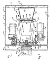
- the illustrated shaping member 90 is a three-dimensional forming frame shown in detail in Figures 4-6.
- the shaping member 90 has a body 95 and ribs 96 and 97 which are made of a bar-like material, such as metal rod.
- the body 95 is V-shaped (when viewed from the top) and comprises a pair of leg portions 98 connected together by a rounded nose portion 99. (See Figure 4.) These components of the body 95 are positioned in a common plane which is titled in the downstream direction in the cushioning conversion machine 20. (See Figures 1 and 2.)
- the leg portions 98 and nose portion 99 are dimensioned so that the body 95 is approximately 14 inches wide (at its point of maximum width) and approximately 24 inches long.
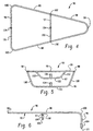
- the upstream rib 96 is generally U-shaped when viewed from the downstream end and comprises a pair of side leg portions 100 connected together by a bottom leg portion 101.
- the bottom leg portion 101 is generally linear and extends laterally approximately eight inches.
- the side leg portions 100 are also generally linear and extend approximately 5 3/4 inches.
- the bottom end of each of the side leg portions 100 is connected, via a rounded corner, to respective sides of the bottom leg portion 101.
- the upper ends of each of the side leg portions 100 is connected, via a rounded comer, to the upstream end of respective leg portions 98 of the body 95.
- the body 95 and the rib 96 are formed from a continuous piece of rod-like material.
- the downstream rib 97 is also generally U-shaped when viewed from the downstream end and comprises a pair of side leg portions 102 connected together by a bottom leg portion 103.
- the bottom leg portion 103 is generally linear and extends approximately 3 inches.
- the side leg portions 102 are also generally linear and extend approximately 2 3/4 inches.
- the bottom end of each of the side leg portions 102 is connected, via a rounded corner, to respective sides of the bottom leg portion 103. (See Figure 5.)
- the upper ends of each of the side leg portions 102 are connected to aligned sections of the leg portions 98 of the body 95, these sections being located approximately 13 1/8 inch from the upstream rib 96. (See Figure 6.)
- the shaping member 90 may additionally include coupling components 104 which are used in the mounting of the shaping member to the machine's frame 36.
- these connecting components are tube-like receptacles attached to the center of the bottom leg portions 101 and 103 of the ribs 96 and 97.
- mounting rods would be coupled to these components so that the shaping member 90 could be suspended in its correct orientation, such as from a strap (not shown) extending between the upstream and downstream ends of the machine frame 36.
- the forming assembly 52 may include the chute and/or the shaping member disclosed in U.S. Patent Application No. 08/487,179.
- a chute has an inlet end which is outwardly flared in a trumpeted fashion to facilitate passage of the stock material into the shaping chute.
- the trumpet-like inlet may eliminate the need for the transverse guide structure 93.
- Such a shaping member is longitudinally formed into a U-shape comprised of a first leg portion attached to a top wall of the chute and a second leg portion extending into the chute generally parallel with the bottom wall of the chute.
- the guide tray 94 is directly mounted on the frame base wall 43; while the transverse guide structure 93 and the converging chute 92 are mounted on the guide tray 94.
- the guide tray 94 is trapezoidal in shape, as viewed in plan, having a broad upstream side 105 and a parallel narrow downstream side 106.
- the broad side 105 is positioned downstream of at least a portion of the shaping member 90.
- the narrow side 106 is positioned adjacent the outlet opening in the frame end wall 46 and includes a rectangular slot 107 to accommodate the feed assembly 54.
- the guide tray 94 is not positioned parallel with the frame base wall 43, but rather slopes away (upwardly in Figures 1 and 2) from the frame base wall 43 to the feed assembly 54.
- the converging chute 92 is mounted on the guide tray 94 upstream of at least a portion of the shaping member 90 and downstream slightly from the broad side 105 of the guide tray 94.
- the transverse guide structure 93 is mounted on the guide tray 94 just upstream of the entrance mouth of the converging chute 92.
- the transverse guide structure 93 includes rollers 108 rotatably mounted on a thin U-bracket 109. The distal ends of the U-bracket 109 are secured to the guide tray 94. Except for this mounting arrangement, the transverse guide structure 93 is similar to the "rollers and wire frame" disclosed in U.S. Patent No. 4,750,896.
- the stock material 22 travels over the guide tray 94, under the bottom leg portions 101 and 103 of the ribs 96 and 97 of the shaping member 90, between the rollers 108 of the transverse guide structure 93, and into the converging chute 92.
- the stock material 22 will emerge from the chute 92 as the continuous unconnected strip.
- the emerging strip is guided to the feed assembly 54 by the narrow downstream end 106 of the guide tray 94, which extends from the outlet opening of the chute to the outlet opening in the frame end wall 46.
- the feed assembly 54 includes rotating feed members between which the stock material 22 travels, specifically loosely meshed horizontally arranged drive gear 124 and idler gear 126.
- the gears 124 and 126 are turned the appropriate direction, which in Figure 2 would be clockwise for gear 124 and counterclockwise for gear 126, the central band of the strip is grabbed by the gear teeth and pulled downstream through the nip of gears 124 and 126. This same "grabbing" motion caused by the meshing teeth on the opposed gears 124 and 126 simultaneously compresses or "coins" the layers of the central band together thereby connecting the same and forming the connected strip.
- the drive gear 124 is positioned between the frame base wall 43 and the guide tray 94 and projects through the rectangular slot 107 in the guide tray 94.
- the gear 124 is fixedly mounted to a shaft 130 which is rotatably mounted to the upstream side of the frame end wall 46 by bearing structures 131.
- a sprocket 132 at one end of the shaft accommodates a chain 133 which connects the shaft 130 to a speed reducer 136.
- the speed reducer 136 acts as an interface between the feed assembly 54 and the feed motor 55 for controlling the rate of "pulling" of the stock material 22 through the machine 20.
- the feed motor 55 and the speed reducer 136 are mounted on the frame base wall 43 at approximately the same level as the forming assembly 52.
- the idler gear 126 is positioned on the opposite side of the guide tray 94 and is rotatably mounted on a shaft 140.
- Shaft brackets 142 attached to an upstream side of the frame end wall 46 non-rotatably support the ends of the shaft 140 in spring-loaded slots 144.
- the slots 144 allow the shaft 140, and therefore the idler gear 126, to "float" relative to the drive gear 124 thereby creating an automatic adjustment system for the feed assembly 54.
- first and second tie members would be movably connected to the shaft 140 and would extend transversely with respect to the shaft 140.
- Each of the tie members would have one end in fixed transverse position relative to the machine's housing 36 and an adjustable stop which is selectively adjustable towards and away from the shaft 140.
- a spring member would be interposed between the shaft 140 and the adjustable stop to resiliently bias the shaft 140 towards the shaft 130. In this manner, the pinch force applied by the rotating feed members 124 and 126 could be adjusted without changing a minimum set distance between the shafts 130 and 140.
- the rotating feed members 124 and 126 may be of the type contained in the stitching assembly disclosed in U.S. Patent Application No. 08/607,607. (This application is assigned to the assignee of the present application and its entire disclosure is hereby incorporated by reference.)
- the first rotating feed.member would have a plurality of radially outwardly extending projections around its circumference and the projections would have axially spaced apart segments defining a recess therebetween.
- the second rotating feed member would have axial punch segments which each include a peripheral edge portion for receipt into the first member's recesses.
- the peripheral edge portions would have opposite corners which are cooperative with the first member's projections to cut a row of slits in the overlapped portions of the stock material to interlocking these overlapped portions.
- the feed assembly 54 transforms the unconnected strip into the connected strip and this strip travels through the outlet opening in the frame end wall 46.
- the connected strip is then cut by the cutting assembly 56 into cut sections 32 of the desired length.
- the cutting assembly 56 may be of any suitable type, such as the types disclosed in U.S. Patent No. 5,123,899, the type disclosed in U.S. Patent Application No. 08/110,349, and/or the type disclosed in U.S. Patent Application No. 08/188,305. (This patent and these applications are assigned to the assignee of the present invention and their entire disclosures are hereby incorporated by reference.
- the connected strip is divided into cut sections 32 of the desired length and these cut sections 32 then travel downstream to the post cutting assembly 58.
- a cut section 32 emerging from the post-cutting assembly 58 may be directed to a desired packing location, the conversion of stock material 22 to cut sections 32 of relatively low density pad-like cushioning dunnage product now being complete.
- the cushioning conversion machine 20 may be viewed as comprising a conversion assembly 30 (i.e., the forming assembly 52, the feed assembly 54, etc.) which converts multi-ply stock material 22 into a three-dimensional cushioning product 32 and a stock supply assembly 50 which supplies the multi-ply stock material to the conversion assembly.
- the conversion assembly includes the forming assembly 52 which inwardly turns the lateral regions of the stock material 22 as it travels downstream therethrough.
- the stock supply assembly 50 includes the separating device 74 which separates the individual plies 24, 26 and 28 of the stock material 22 upstream of the forming assembly 52.
- the inwardly turning of the stock material begins just downstream of the separating device 74.
- the separating members 76, 77 and 78 of the separating device 74 extend between the stock supply brackets 62 and extend in a linear path in a direction perpendicular to the upstream-downstream direction.
- the plies 24, 26 and 28 of the stock material 22 traveling over the separating members 76, 77 and 78 are forced to follow a straight transverse path and are prevented from inwardly turning in the same direction as the forming assembly 52.
- the lateral regions of the stock material must abruptly begin their inwardly taming after engaging the separating members. This abruptness may effect the conversion process by, for example, resulting in excessive tension in the lateral regions which sometimes leads to ripping or tearing of the paper.
- the stock supply assembly 350 may be incorporated into a cushioning conversion machine, such as the cushioning conversion machine 20 described above or any other cushioning conversion machine or method which falls within the scope of the claims.
- the stock supply assembly 350 allows a more gradual transition between the supply of the stock material to the machine's conversion assembly and the inward taming of lateral edges by the conversion assembly. Such an arrangement is believed to reduce edge-tension in the stock material and/or otherwise enhance the conversion process.
- the stock supply assembly 350 like the stock supply assembly 50, discussed above, includes two laterally spaced brackets 362 which are essentially the same as the brackets 62.
- the brackets 362 have two legs 364 and 365 extending perpendicularly outward from a flat connecting base wall 366.
- the legs 364 have open slots 370 in their distal ends which cradle a supply rod 372 such as the supply rod 372 discussed above which is designed to extend relatively loosely through the hollow tube 29 of the stock roll 21 whereby as the stock material 22 is pulled through the machine 20 by feed assembly 54, the tube 29 will freely rotate thereby dispensing the stock material 22.
- the legs 364 may be replaced with other bracket portions if desired, such as the multi-position stock roll support bracket shown in U.S.
- the other legs 365 of the U-brackets 362 extend from an intermediate portion of the frame end wall 44 and cooperate to mount a separating device, indicated generally at 374.
- the separating device 374 includes three transversely extending members 376, 377 and 378.
- the number of separating members namely three, corresponds to the number of paper layers or webs or plies of the stock material 22.
- the separating device 374 separates the layers 24, 26 and 28 of paper prior to their passing to the forming assembly 52.
- the bracket legs 365 also cooperate to support a constant-entry member 380 which is rotatably mounted on the distal ends of the legs.
- the member 380 may be of essentially the same construction and perform essentially the same function as the constant entry bar 80 discussed above. Particularly, the constant-entry member 380 provides a non-varying point of entry for the stock material 22 into the separating device 374 and forming assembly 52, regardless of the diameter of the stock roll 21.
- the member 380 may also be other than cylindrical in shape and may have a bowed or convex shape. That is, the constant entry member may progressively decrease in diameter from the middle thereof to its ends, preferably in a manner that provides a rounded or convexly curved outer surface similar to what is shown in Fig. 10.
- such a rounded constant entry member preferably a roller, may be incorporated into a cushioning conversion machine like that shown in Figs. 1-3 in combination with or separately from the other novel features of the present invention.
- the stock supply assembly 350 may additionally comprise a dancer roll, such as a gravity or spring biased dancer roll, which defines the path of the stock material from the stock-dispensing device to the constant entry roller 380.
- a dancer roll such as a gravity or spring biased dancer roll
- the outer separating member 376 includes end portions 400 and a central portion 402 extending therebetween.
- the end portions 400 are inwardly tapered relative to the central portion 402 towards the respective ends of the member 376.
- the inwardly tapered lateral end portions 400 of the member 376 are positioned to engage the ends of the lateral portions of the outer ply 24 of the stock material. In this manner, the outer ply 24 of stock material engaging the outer separating member 376 is not forced to follow a straight transverse path. Instead, the lateral portions of the outer ply 24 of stock material are inwardly urged in the same direction as the forming assembly inwardly turns the lateral edges of the stock material. This allows a gradual, rather than abrupt, transition between separating device 374 and the forming assembly 52 thereby reducing the chance of excessive edge-tension and/or otherwise enhancing the conversion process.
- the end portions 400 preferably each occupy between 2% - 6% of the entire axial length of the separating member 376, with the central portion 402 occupying the other 96%- 88% of the axial length of the member 376. More preferably, the end portions 400 each occupy 3%- 5%, and more preferably approximately 4% of the member's axial length. Thus, when the cushioning conversion machine is designed to convert stock material which is approximately 30 inches wide, the end portions 400 will preferably each occupy the outer 1.2 inches of the member 376, with the center portion 402 occupying the center 27.6 inches of the member 376.
- the illustrated outer separating member 376 comprises a rod 404, a sleeve 406, and a pair of end caps 408 connected to each end of the sleeve 406.
- the rod 404 is non-rotatably mounted between the bracket legs 376 and the sleeve 406 and caps 408 are rotatably mounted about the rod 404.
- the sleeve 406 forms the center portion 402 of the separating member 376 and is preferably cylindrical with a constant circular radial cross-sectional shape along its axial dimension.
- the caps 408 each include a head 410 and a plug 412 connected to the head 410.
- the head 410 forms the inwardly tapering end portions 400 of the separating member 376.
- the head 410 has a circular radial cross-section shape which decreases in size along its axial dimension and an axial cross-sectional shape resembling a top-truncated parabola.
- the plugs 412 extend from the axially inner end of the respective head 410 and are sized for tight inserted receipt into the ends of the sleeve 406 whereby the sleeve 406 will not rotate relative to the end caps 408.
- the end caps 408 are preferably made of suitable material, such as plastic, so that they form a bearing surface relative to the rod 404.
- the outer separating member 376 may additionally include a pair of springs 414 positioned around the rod 404 on opposite sides of the end caps 408, to provided biased transverse centering of the sleeve 406 and the caps 408 on the rod 404.
- FIG. 10 Another outer separating member 476 is shown in Figure 10, which includes inwardly tapered end portions 490 and a central portion 492 extending therebetween.
- the separating member 476 comprises a rod 494 which is non-rotatably mounted between the bracket legs 365 and a sleeve 496 which is mounted for rotation around the rod 494.
- the sleeve 496 forms the central portion 492 of the member and also the inwardly tapered lateral end portions 490 of the member.
- the sleeve 496 is cylindrical and has a circular radial cross-sectional shape which changes size along its axial dimension.
- the radial cross-sectional size of the sleeve 496 preferably changes gradually along the central portion 492 of the separating member and more dramatically along the lateral end portions 492 of the separating member 476.
- the outer separating member 476 may additionally include a pair of springs 614 positioned around the rod 494 on opposite sides of the sleeve 496, to provided biased transverse centering of the sleeve 496.
- the intermediate separating member 377 is positioned to engage the intermediate ply 26 of the multi-ply stock material and is preferably of the same construction as the intermediate member 77 discussed above in connection with the separating device 76 of the machine 20.
- the intermediate member 376 includes a sleeve or rod having the same diameter along its entire axial length whereby it does not include inwardly tapered lateral end portions. This more economical non-tapered construction is preferred since the intermediate ply 26 experiences less excessive edge-tension problems than the outer ply 24 and/or the inner ply 28.
- the cross-sectional area (or diameter) of the intermediate member 377 is preferably less than the cross-sectional area of the central portion 402 of the outer member 376 or the central portion 502 of the outer member 476.
- the inner separating member 378 is positioned to engage the inner ply 28 of the multi-ply stock material.
- the member 378 is preferably of the same general construction as the outer separating member 377 or the outer separating member 504. In this manner, the inner ply 28 of stock material engaging the inner separating member 378 is not forced to follow a straight transverse path. Instead, the lateral portions of the inner ply 28 are inwardly urged in the same direction as the forming assembly 52 inwardly turns the lateral edges of the stock material. This allows a gradual, rather than abrupt, transition between separating device 376 and the forming assembly 52 thereby reducing the chance of excessive edge-tension and/or otherwise enhancing the conversion process.
- the overall axial length of the inner separating member 378 is not the same as the overall axial length of the outer separating member 376. More preferably, the inner separating member 378 is slightly longer than the outer separating member, in the range of 11 ⁇ 2% to 5% and more preferably in the range of 2.6%. This is length arrangement is preferred since the inner separating member 378 engages the inner ply 28 which becomes the outer ply in the cushioning product 32 and thus must envelope or encapsulate the other plies 24 and 26.
- two of the separating members include the inwardly tapering end portions.
- a stock supply assembly wherein only the outer separating member includes the inwardly tapering end portions, wherein only the inner separating member includes the inwardly tapering end portions, or any other arrangement wherein at least one of the separating members includes the inwardly tapering end portions is possible with , and contemplated by, the present invention.
- the incorporation of such a transversely extending member into a cushioning conversion machine which does not include a separating device is possible with, and contemplated by, the present invention.
- the resulting method will comprise the steps of the steps of supplying a multi-ply stock material and converting the stock material into a three dimensional cushioning product.
- the converting step includes the step of inwardly turning lateral portions of the stock material as the stock material travels in a downstream direction.
- the supplying step includes the steps of dispensing the stock material from a continuous sheet of mufti-ply stock material and engaging at least one ply of the dispensed stock material with a transversely extending member which inwardly urges the lateral end portions of the at least one ply in the same direction as the inwardly taming step of the converting step.
- the present invention provides a cushioning conversion machine and method in which the stock supply assembly or step allows a more gradual transition between the supply of the stock material to the machine's conversion assembly and the inward turning of lateral edges by the conversion assembly.
- the constant-entry device 80 provides a non-varying point of entry for the stock material 22 into the separating device 74 and forming assembly 52, regardless of the diameter of the stock roll 21.
- the point of entry of the stock material 22 into the separating device 74 remains constant. This consistency is believed to facilitate the production of uniform cushioning product.
- the sleeve 84 As the stock material being drawn into the conversion assembly 30 from the stock roll 21, it will exert a downward force on the sleeve (or guide roller) 84 of the constant-entry device 80 by reason of the pulling force needed to rotate the stock roll 21.
- the sleeve 84 is positioned at the optimum entry point for the stock material when it is subjected to normal downward forces associated with steady state operation of the machine throughout the normal diameter range of the stock roll 21.
- the pulling force and consequently the tension of the stock material may increase to a point that causes tearing of the paper.
- the shaping member 90 it is positioned partially within the chute 92.
- the stock material 22 travels around the shaping member 90 and through the chute 92 as it passes through the forming assembly 52.
- the lateral regions of the stock material 22 are inwardly turned over the leg portions 98 of the V-shaped body 95 of the shaping member.
- the leg portions 98 of the body 95 may be viewed as forming a turning perimeter for the lateral regions of the stock material 22. Since these leg portions 98 are positioned in a common plane, all of the portions of the turning perimeter of the shaping member 90 are positioned in a common plane. Thus, in the shaping member 90, there are no protrusions which project beyond the co-planar portions (the legs 98) of the turning perimeter.
- the bottom wall 98 of the rib 96, the bottom wall 100 of the rib 97, and the nose portion 99 of the body 95 hold the central regions of the stock material 22 as its lateral regions are inwardly turned.
- the rib bottom walls 98 and 100 and the nose portion 99 are situated in the same plane in a triangular configuration. (See Figure 10.) Particularly, when a line is drawn from one of the ends of the bottom leg portion 101 of the upstream rib 96 to the vertex of the nose portion 99 of the body 95, it passes through the corresponding end of the bottom leg portion 103 of the downstream rib 96.
- the nose portion 99 of the body 95 of the shaping member 90 is the downstream edge of the shaping member 90.
- the nose portion 99 is essentially a "rounded corner” or “curved vertex” between the side leg portions 98 of the shaping member 90. As such, the nose portion 99 does not include a transverse linear component.
- the shaping member 590 according to the present invention is shown isolated and in detail in Figures 12-14.
- the shaping member 590 is made by modifying or retrofitting the shaping member 90 discussed above.
- the shaping member 590 may also be formed independently rather than as a retrofit
- the shaping member 590 is a three-dimensional forming frame having a body 595 and ribs 596 and 597.
- the body 595 is substantially similar to the body member 95 of the shaping member 90 and thus is V-shaped (when viewed from the top) and comprises a pair of leg portions 598 connected together by a nose portion 599. (See Figure 15.) When incorporated into the cushioning conversion machine 20, these components of the body 595 would be positioned in a common plane which is tilted in the downstream direction.
- the leg portions 598 are the same as the leg portions 98 of the shaping member 90 whereby the body 595 is approximately 24 inches long.
- the width of the nose portion 599 is increased by two Inches when compared to the nose portion 99 of the shaping member 80.
- the increase in width of the nose portion 599 results in it having more of a flattened U-shape as opposed to the rounded comer shape of the nose portion 99 of the shaping member 90. Also, the increase in width of the nose portion 599 results in the body 595 being approximately sixteen inches wide. as compared to the body 95 which is approximately fourteen inches wide.
- the upstream rib 596 which is also increased width by two inches, is generally U-shaped when viewed from the downstream end and comprise a pair of side leg portions 600 connected together by a bottom leg portion 601.
- the side leg portions 600 are essentially the same as the side leg portions 100 of the shaping member 90 and thus are generally linear and extend approximately 5 3/4 inches.
- the bottom leg portion 601 is similar to the bottom leg portion 101 of the shaping member 90 except that its width is increased by the noted two inches whereby it extends approximately ten inches as compared to the bottom leg portion 101 which extends eight inches.
- the upper ends of each of the side leg portions 600 is connected, via a rounded comer, to the upstream end of respective leg portions 598 of the body 595. (See Figure 14.)
- the downstream rib 597 is also generally U-shaped when viewed from the downstream end and comprises a pair of side leg portions 602 connected together by a bottom leg portion 603.
- the side leg portions 602 are essentially the same as the side leg portions 102 of the shaping member 90 and thus are generally linear and extend approximately 2 3/4 inches.
- the bottom leg portion 603 is essentially the same as the bottom leg portion 103 of the shaping member 90 except that its width is increased by two inches whereby it extends approximately five inches as compared to the bottom leg portion 101 which extends three inches.
- the bottom end of each of the side leg portions 602 is connected via a rounded comer, to respective sides of the bottom leg portion 603. (See Figure 13.)
- the upper ends of each of the side leg portions 602 is connected to aligned sections of the leg portions 598 of the body 595, these sections being approximately 13 1/8 inch from its upstream end. (See Figure 14.)
- the increase in width of the nose portion 599 is accomplished by a two inch extension piece centrally inserted therein.
- the nose portion 599 could centrally cut and then the extension piece sandwiched between the cuts and secured in place by welding.
- the increase in width of the bottom leg portions 601 and 603 of the ribs 596 and 597 is accomplished by two inch extension pieces centrally inserted therein.
- the portions 595, 596 and 597 could be formed in the same manner as the portions 95,96 and 97 of the shaping member 90 to obtain the increase in width.
- the shaping member 590 may additionally include coupling components 604 of essentially the same construction, and for the same purpose as, the coupling components 104 of the shaping member 90.
- the shaping member 590 additionally includes a pair of wing portions 610.
- the wing portions 610 are made of the same bar-like material as the rest of the shaping member 590.
- Each wing portion 610 is generally L-shaped having a long leg portion 612 and a shorter leg portion 614 extending from one end thereof.
- the union between the leg portions 612 and 614 is a rounded comer forming a slightly less than perpendicular (i.e., 75° to 80°) angle.
- the leg portion 612 extends approximately 9 inches and the leg portion 614 extends approximately 11/2 Inches.
- the wing portions 610 are attached to the top of the side leg portions 598 of the body 595 and extend upwardly therefrom. More specifically, the distal end of the leg portion 612 of one of the wing portions 610 is secured to one of the side leg portions 598 just downstream of the connection point for the downstream ribs 597 and 610. To this end, the leg portion 612 preferably has a contoured edge so that It can lay substantially flush against the top surface of the leg portion 598. (See Figures 15 and 17.) The distal end of the leg portion 614 of this wing portion is secured to this same leg portion 598 just upstream of the comer forming the transition to the nose portion 599. Thus, in the modified forming assembly 52, the wing portions 610 will be positioned within the chute 92.
- the shaping member 590 further includes a downstream rib 620 which comprises a pair of side leg portions 622 and a bottom leg portion 623 extending therebetween.
- the bottom leg portion 623 is generally linear and extends approximately 6 inches, as compared to the bottom leg portion 603 of the rib 597 which extends approximately five inches.
- the side leg portions 622 extend approximately 3 3/16 inches, as compared to the side leg portions 602 of the rib 597 which extend 2 3/4 inches.
- each of the side leg portions 622 is connected via a rounded comer, to respective sides of the bottom leg portion 623.
- the side leg portions 602 of the rib 597 slant inwardly to meet the bottom leg portion 603, the side leg portions 622 of the rib 620 extend generally perpendicularly from the plane of the body 595.
- the upper ends of each of the side leg portions 622 is connected to aligned sections of the leg portions 598 of the body 595, these sections being approximately 13 1/8 inch from its upstream end and thus at the same point as the side leg portions 602 of the rib 597 are connected to the body. (See Figure 14.)
- the lateral regions of the stock material 22 are inwardly turned over the upper portions of the shaping member 590, particularly the leg portions 598 of the V-shaped body 595 and the wing portions 610.
- the leg portions 598 and the wing portions 610 may be viewed as forming a taming perimeter for the lateral regions of the stock material 22.
- the leg portions 598 of the body 595 are positioned In a common plane, the wing portions 610 project beyond this plane. In this manner, the wing portions 610 form protrusions which project beyond (and more particularly extend perpendicularly from) the co-planar portions of the turning perimeter.
- protrusions formed by the wing portions 610 results in an increase in the loft of the cushioning product produced by the cushioning conversion machine 20. Also, the geometry of the wing portions 610 results in the protrusion increasing In the downstream direction, in contrast to the overall geometry of the shaping member 590 which decreases in the downstream direction.
- the bottom leg portion 601 of the rib 596, the bottom leg portion 623 of the rib 620, and the nose portion 599 of the body 595 hold the central regions of the stock material 22 as its lateral regions are inwardly turned. In this manner, the portions 601, 623 and 599 form a "holding surface" surface which holds the central regions of the stock material while its lateral regions are inwardly turned.
- the bottom leg portion 601 of the rib 596, the bottom leg portion 603 of the rib 596 and the nose portion 599 are situated in the same plane in a triangular configuration. (See Figure 13.) Particularly, when a line is drawn from one of the ends of the bottom leg portion 601 of the upstream rib 596 to the vertex of the nose portion 599 of the body 595, it passes through the corresponding end of the bottom leg portion 603 of the downstream rib 596. When a line is drawn from the other end of the bottom leg portion 601 of the upstream rib 596 to the vertex of the nose portion 599 of the body, it passes through the other end of the bottom leg portion 603 of the downstream rib.
- the bottom leg portion 603 of the rib 596 extends below this line whereby the bottom leg portion 623 of the rib 596 forms a projection which project beyond a plane extending from the downstream edge of the surface (the leg portion 601) to the upstream edge of the surface (the nose portion 599). Instead, the bottom leg portion 623 extends below this plane thereby fordng the central regions of the stock material 22 to travel an Increased distance around the rib 620. This increased travel path at an intermediate region of the shaping member 590 for the central regions of the stock material results In less stock material being inwardly turned to form the central portion of the cushioning product.
- the rib 620 extends laterally beyond and also extends below the rib 597 thereby "overshadowing" or “superseding” the rib 597 whereby it does not contact the stock material 22 during the forming process. For this reason, if the shaping member 590 was not being made as a retrofit to the shaping member 90, the rib 597 could be eliminated from shaping member 590. In such a case, the coupling component 104 could instead be attached to a central region of the rib 610.
- the nose portion 599 of the body 595 forms the downstream edge of the shaping member 590.
- the nose portion 599 of the body 595 of the shaping member 590 is transversely extended 2 inches when compared to the nose portion 99 of the body 95 of the shaping member 90.
- the nose portion 99 of the shaping member 90 is essentially a "rounded comer" or "curved vertex" between the side leg portions 98 of the body 95 and does not include a transverse linear component.
- the nose portion 599 of the body portion 595 of the shaping member 590 includes a transverse linear component which extends in a direction perpendicular to the upstream-downstream direction.
- the shaping member 590 may be used with the separator device 574 and the constant entry device 580.
- the shaping member 590 may be advantageously incorporated into a cushioning conversion machine without these devices, or with any other cushioning conversion machine or method which falls within the scope of the claims.
- certain portions of the shaping member 590 may be advantageous when it is desired to change certain features of a cushioning product. For example, if it were desired to increase the loft of a cushioning product, the wing portions 610 could be added to a shaping member. Additionally or alternatively, if it were desired to decrease the amount of stock material which is inwardly turned to form the central portion of the cushioning product, the rib 620 could be added to a shaping member.
- a further addition or alternative is to modify the downstream end of a shaping member to include a transverse linear component.
Abstract
Description
- The present invention relates generally as indicated to a cushioning conversion machine and method. More particularly, the present invention relates to a separator device, a constant-entry device, and/or a shaping member for use in a cushioning conversion machine or method.
- In the process of shipping an item from one location to another, a protective packaging material is typically placed in the shipping case, or box, to fill any voids and/or to cushion the item during the shipping process. Some conventional commonly used protective packaging materials are plastic foam peanuts and plastic bubble pack. While these conventional plastic materials seem to adequately perform as cushioning products, they are not without disadvantages. Perhaps the most serious drawback of plastic bubble wrap and/or plastic foam peanuts is their effect on our environment. Quite simply, these plastic packaging materials are not biodegradable and thus they cannot avoid further multiplying our planet's already critical waste disposal problems. The non-biodegradability of these packaging materials has become increasingly important in light of many industries adopting more progressive policies in terms of environmental responsibility.
- These and other disadvantages of conventional plastic packaging materials has made paper protective packaging material a very popular alternative. Paper is biodegradable, recyclable and renewable; making it an environmentally responsible choice for conscientious industries. While paper in sheet form could possibly be used as a protective packaging material, it is usually preferable to convert the sheets of paper into a relatively low density pad-like cushioning dunnage product. This conversion may be accomplished by a cushioning conversion machine, such as that disclosed in U.S. Patent No. 5,322,477. This patent is assigned to the assignee of the present application and its entire disclosure is hereby incorporated herein by reference.
- The cushioning conversion machine disclosed in U.S. Patent No. 5,322,477 comprises a conversion assembly which converts multi-ply stock material into a three-dimensional cushioning product and a stock supply assembly which supplies the multi-ply stock material to the conversion assembly. The conversion assembly includes the forming assembly which inwardly turns the lateral regions of the stock material as it travels downstream therethrough. This inward turning results the lateral regions of the stock experiencing edge tension which sometimes results in ripping or tearing of the stock material.
- A need remains for further improvements to prevent excessive edge tension and/or the tearing associated therewith. This need is especially critical for the conversion of lesser quality and/or short fiber paper. Additionally or alternatively, a need remains for other improvements to the cushioning conversion machine to work in conjunction with tension-distributing devices or otherwise improve or enhance the conversion process.
- US patent number 3 799 039 discloses a cushioning dunnage producing mechanism which is of compact nature utilising a single role of stock material comprising multiples of sheetlike material, such as paper stock, which are separated as they are pulled off the composite roll, rolled or urged inwardly at their lateral edges and into generally superimposed condition and passed into a crumpler section where meshed gears coin or stitch the confronting portions of the rolled edges of the stock material together generally centrally in a direction lengthwise thereof, to hold the dunnage product in a lightweight, highly compressible, padlike configuration.
- The present invention provides a stock supply arrangement which prevents the stock material from abruptly experiencing inward turning just downstream of the stock supply assembly, or more particularly the separating device. The stock supply arrangement of the present invention allows a more gradual transition between the supply of the stock material to the conversion assembly and the inward turning of lateral regions of the stock material by the conversion assembly. Such a gradual transition is believed to reduce edge-tension in the stock material and/or otherwise enhance the conversion process.
- More particularly, the present invention provides a cushioning conversion machine comprising a conversion assembly which converts a multi-ply stock material into a three dimensional cushioning product and a stock supply assembly which supplies the multi-ply stock material to the conversion assembly. The conversion assembly includes a forming assembly which inwardly turns lateral regions of the stock material as the stock material travels therethrough in a downstream direction. Preferably, the forming assembly comprises a chute and a shaping member positioned at least partially within the chute with the stock material passing through the chute and around the shaping member as it travels through the forming assembly.
- According to a first embodiment of the invention there is provided a cushioning conversion machine as claimed in claim 1. The stock supply assembly may include a stock-dispensing device which dispenses the muiti-ply stock material from a continuous sheet or roll thereof and a separating device which separates the plies of the dispensed stock material upstream of the forming assembly. The separating device may include a plurality of transversely extending separating members which are positioned to engage respective plies of the multi-ply stock material. At least some of the separating members (and preferably all) are shaped to permit an initial inward turning of the lateral regions of the stock material in the same direction as the forming assembly. In this manner, there is a more gradual transition between the supply of the stock material to the machine's conversion assembly and the inward turning of lateral regions by the conversion assembly.
- The preferred separating members are shaped such that tension is substantially evenly distributed throughout the full width of the stock material. At least some (and preferably all) of the separating members have a bowed or curved configuration and thus do not follow a transverse linear path perpendicular to the upstream-downstream direction. The direction of concavity of the bowed separating members corresponds to the direction which the lateral regions of the stock material are inwardly turned. The magnitude of concavity of the bowed separating members is such that there will be a gradual transition between the curvature of the stock material from the separating device to the forming assembly.
- In the preferred cushioning conversion machine, the stock supply assembly is adapted to supply stock material which is between 25 to 35 inches wide and more preferably between 27 and 30 inches wide. The conversion assembly converts this stock material into a cushioning product which is approximately 8 to 9 inches wide. With such a cushioning conversion machine, the radii of curvature of the bowed separating members is preferably between 26 and 34 inches, more preferably between 27 and 33 inches, and even more preferably between 28 and 32 inches. The radii of curvature preferably varies between the bowed separating members, and preferably increases from the separating member which engages the ply of stock material which forms the inner ply in the cushioning product to the separating member which engages the ply of stock material which forms the outer ply in the cushioning product. Additionally, the radii of curvature of the separating members are preferably concentric to create a "bull's eye" arrangement.
- The separating members including the inwardly tapered lateral end portions preferably comprise a non-rotatable rod and a sleeve. The sleeve is rotatably mounted around the rod and defines at least the central portion of the separating member. In one embodiment of the invention, the sleeve defines only the central portion and the separating member includes end caps which define the inwardly tapering end portions. In another embodiment of the invention, the sleeve defines both the central portion and the inwardly tapering end portions of the separating member.
- In the preferred embodiment, the transversely extending member having the inwardly tapered end portions is incorporated into the machine's separating device. However, the incorporation of such a member into a cushioning conversion machine which does not include a separating device is possible with, and contemplated by, the present invention. The stock supply assembly of such a machine would include a stock-dispensing device which dispenses the multi-ply stock material from a continuous sheet thereof and the transversely extending member would be positioned to engage at least one of the plies of the dispensed mutli-ply stock material.
- The present invention also provides a cushioning conversion method comprising the steps of supplying a multi-ply stock material and converting the stock material into a three dimensional cushioning product. The converting step includes inwardly turning lateral portions of the stock material as the stock material travels in a downstream direction. The supplying step includes dispensing the stock material from a continuous sheet of multi-ply stock material and engaging at least one ply of the dispensed stock material with a transversely extending member which allows inward urging of the lateral end portions of the at least one ply in the same direction as the inwardly taming step of the converting step. Preferably, the supplying step also includes the step of separating the plies of stock material and the engaging step is performed at the same time as said separating step.
- The foregoing and other features of the invention are hereinafter fully described and particularly pointed out in the claims. The following description and annexed drawings setting forth in detail a certain illustrative embodiment of the invention, this being indicative, however, of but a few of the various ways in which the principles of the invention may be employed.
-
- Figure 1 is a side view of the cushioning conversion machine disclosed in U.S. Patent No. 5,322,477, the machine being shown positioned in a horizontal manner, loaded with stock material, and with an outer housing side wall removed for clarity of illustration.
- Figure 2 is an opposite side view of the cushioning conversion machine shown in Figure 1.
- Figure 3 is a top plan view of the cushioning conversion machine of Figure 1, without stock material being loaded and as seen along line 3-3 in Figure 1.
- Figures 4, 5, and 6 are top, upstream end, and side views, respectively, of a shaping member used in the cushioning conversion machine shown in Figure 1.
- Figure 7 is a side schematic view of a stock supply assembly according to the present invention, the stock supply assembly including a separating device with an inner separating member, an outer separating member, and an intermediate separating member.
- Figure 8 is a top view of the outer or inner separating member.
- Figure 9 is a top view of end cap of the outer separating member.
- Figure 10 is a top view of another outer or inner separating member which may be used in a stock supply assembly according to the present invention.
- Figure 11 is a side view of a component of a constant entry device of the stock supply assembly according to the present invention.
- Figures 12, 13 and 14 are top, upstream end, and side views, respectively of a shaping member according to the present invention.
-
- The cushioning conversion machine disdosed In U.S. Patent No. 5,322,477 is shown in Figures 1-3 and is indicated generally at 20. In Figures 1 and 2, the
machine 20 is shown positioned in a horizontal manner and loaded with aroll 21 of sheet-like stock material 22. Thestock material 22 may consist of three superimposed webs or layers 24, 26, and 28 of biodegradable, recyclable and reusable thirty-pound Kraft paper rolled onto a hollowcylindrical tube 29. A thirty-inch roll of this paper, which is approximately 450 feet long, will weigh about 35 pounds and will provide cushioning equal to approximately four 15 ft3 bags of plastic foam peanuts while at the same time requiring less than one-thirtieth the storage space. - As is explained in more detail below, the
machine 20 includes conversion assemblies (hereinafter collectively referred to as the conversion assembly 30) which convert thestock material 22 into a continuous unconnected strip having lateral pillow-like portions separated by a thin central band. This strip is connected along the central band to form a connected strip which is cut intosections 32 of a desired length. Thecut sections 32 each include lateral pillow-like portions 33 separated by a thin central band and provide an excellent relatively low density pad-like product which may be used instead of conventional plastic protective packaging material. - The
machine 20 includes a housing, indicated generally at 36, having an upstream or "feed"end 38 and a downstream or "discharge"end 40. The terms "upstream" and "downstream" in this context are characteristic of the direction of flow of thestock material 22 through themachine 20. Thehousing 36 is positioned in a substantially horizontal manner whereby an imaginary longitudinal line oraxis 42 from theupstream end 38 to thedownstream end 40 would be substantially horizontal. - The
housing 36 includesside walls 37, a top or coverwall 39, a base plate orwall 43 and twoend walls frame base wall 43 is generally rectangular and extends from theupstream end 38 to thedownstream end 40 of thehousing 36 in a generally horizontal plane. Although not perfectly apparent from the illustrations, the first orupstream wall 44 may be more specifically described as a thin rectangular wall having a rectangular stock inlet opening 47 passing therethrough. Alternatively, instead of theend wall 44, the side andbase walls stock inlet opening 47. The second ordownstream end wall 46 is generally rectangular and planar and includes a relatively small rectangular outlet opening. - The first
frame end wall 44 extends generally perpendicular in one direction from the upstream end of theframe base wall 43. In the illustrated embodiment of Figures 1 and 2, this direction is upward. Thesecond end wall 46 is preferably aluminum and extends in generally the same perpendicular direction from the downstream end of theframe base wall 43. In this manner, thehousing 36 is basically "C" shape and one side of theframe base wall 43, which in this embodiment is the lower side, is a flat uninterrupted surface. Thehousing 36 also includes a box-like extension 49 removably attached to a downstream portion of thebase wall 43. Although not shown in all of the drawings, the frame may be enclosed by a sheet metal housing, includingside walls 37 and a top wall orcover 39. - The
machine 20 further includes astock supply assembly 50, a formingassembly 52, afeed assembly 54 powered by afeed motor 55, a cuttingassembly 56 powered by acutter motor 57, and apost cutting assembly 58. In operation of themachine 20, thestock supply assembly 50 supplies thestock material 22 to the formingassembly 52. The formingassembly 52 causes inward rolling of lateral regions of the sheet-like stock material 22 to form the lateral pillow-like portions 33 of the continuous strip. Thefeed assembly 54 pulls thestock material 22 from thestock roll 21, through thestock supply assembly 50, and through the formingassembly 52 and also connects or stitches the central band of the strip to form the connected strip. As the connected strip travels downstream from thefeed assembly 54, the cuttingassembly 56 cuts the strip intosections 32 of a desired length. These cutsections 32 then travel through thepost-cutting assembly 58. - Turning now to the details of the various assemblies, the
stock supply assembly 50 includes two laterally spacedbrackets 62. Thebrackets 62 are each generally shaped like a sideways "U" and have twowalls wall 66. (See Figures 1 and 2.) For eachbracket 62, the connectingwall 66 is suitably secured to the downstream side of theframe end wall 44, such as with bolts. In the illustrated embodiment, thewall 64 is generally aligned with theframe base wall 43. However, the positioning of thebrackets 62 is sometimes "dropped" so that thewall 64 is situated below (in the illustrated orientation) thebase wall 43. For example, an intermediate portion of the connectingwall 66 may be situated at the same level as thebase wall 43. Additionally or alternatively, a diagonal brace may be used which extends between the connectingwall 66 and thewall 64. - Both of the
walls 64 haveopen slots 70 in their distal end to cradle asupply rod 72 thereby defining a stock-dispensing device. Thesupply rod 72 is designed to extend relatively loosely through thehollow tube 29 of thestock roll 21. As thestock material 22 is pulled through themachine 20 by thefeed assembly 54, thetube 29 will freely rotate thereby dispensing thestock material 22. A pin (not shown) may be provided through one or both ends of thesupply rod 72 to limit or prevent rotation of thesupply rod 72 itself. Theslots 70 and thesupply rod 72 may be viewed as forming the stock-dispensing device of thestock supply assembly 50. - The
other walls 65 of the U-brackets 62 extend from an intermediate portion of theframe end wall 44 and cooperate to mount aseparating device 74. The separatingdevice 74 includes a pair of mountingbrackets 75 and three separatingmembers brackets 75 is secured, as by welding or bolting, to the inner surface to one of thewalls 65 at a distal portion (but not end) thereof. The other of the bar-mountingbrackets 75 is secured to the inner surface of the other of thewalls 65 in the same manner so that the brackets are laterally aligned. The opposite ends of the separatingmembers brackets 75. The number of separating members, namely three, corresponds to the number of paper layers or webs of thestock material 22. - In the
separating device 74, the separatingmembers walls 65 of thebrackets 62. Such sleeves are cylindrical and are sized to axially extend the entire transverse dimension (i.e. width) of themulti-ply stock material 21. Also, each of the sleeves has a circular cross-sectional shape that is of the same diameter along its axial dimension. The sleeves and/or bars may all be of substantially the same diameter or, alternatively, the separatingmember 76 which engages the outer ply of the multi-ply stock material may be of a larger diameter. Details of a separating mechanism similar to the separatingdevice 74 are set forth in U.S. Patent No. 4,750,896. (This patent is assigned to assignee of the present application and its entire disclosure is hereby incorporated by reference.) - The
bracket walls 65 also cooperate to support a constant-entry device 80. The constant-entry device 80 comprises arod 82 fixedly mounted to the distal ends of thebracket walls 65 and asleeve 84, extending the distance between thewalls 65, rotatably positioned about the rod. Although not immediately apparent from the drawings, thesleeve 84 may include side flanges to keep stock material properly centered. Details of a "roller member" or a "bar member" similar to the constant-entry device 80 are set forth in U.S. Patent No. 4,750,896. - After the
stock material 22 is pulled from thestock roll 21 over the constant-entry device 80 and through the separatingdevice 74, it is pulled through the stock inlet opening 47 to the formingassembly 52. The formingassembly 52 includes a three-dimensional bar-like shaping member 90 (or forming frame), a convergingchute 92, atransverse guide structure 93 and aguide tray 94. Thestock material 22 travels between the shapingmember 90 and theframe base wall 43 until it reaches theguide tray 94. At this point, thetransverse guide structure 93 and theguide tray 94 guide thestock material 22 longitudinally and transversely into the convergingchute 92. During this downstream travel, the forming assembly inwardly turns the lateral regions of thestock material 22 to form the lateral pillow-like portions 33 . As the strip emerges from the convergingchute 92, theguide tray 94 guides the strip into thefeed assembly 54. - The illustrated shaping
member 90 is a three-dimensional forming frame shown in detail in Figures 4-6. The shapingmember 90 has abody 95 andribs body 95 is V-shaped (when viewed from the top) and comprises a pair ofleg portions 98 connected together by arounded nose portion 99. (See Figure 4.) These components of thebody 95 are positioned in a common plane which is titled in the downstream direction in thecushioning conversion machine 20. (See Figures 1 and 2.) Theleg portions 98 andnose portion 99 are dimensioned so that thebody 95 is approximately 14 inches wide (at its point of maximum width) and approximately 24 inches long. - The
upstream rib 96 is generally U-shaped when viewed from the downstream end and comprises a pair ofside leg portions 100 connected together by abottom leg portion 101. (See Figure 5.) Thebottom leg portion 101 is generally linear and extends laterally approximately eight inches. Theside leg portions 100 are also generally linear and extend approximately 5 3/4 inches. The bottom end of each of theside leg portions 100 is connected, via a rounded corner, to respective sides of thebottom leg portion 101. (See Figure 5.) The upper ends of each of theside leg portions 100 is connected, via a rounded comer, to the upstream end ofrespective leg portions 98 of thebody 95. (See Figure 6.) In the illustrated embodiment, thebody 95 and therib 96 are formed from a continuous piece of rod-like material. - The
downstream rib 97 is also generally U-shaped when viewed from the downstream end and comprises a pair ofside leg portions 102 connected together by abottom leg portion 103. (See Figure 5.) Thebottom leg portion 103 is generally linear and extends approximately 3 inches. Theside leg portions 102 are also generally linear and extend approximately 2 3/4 inches. The bottom end of each of theside leg portions 102 is connected, via a rounded corner, to respective sides of thebottom leg portion 103. (See Figure 5.) The upper ends of each of theside leg portions 102 are connected to aligned sections of theleg portions 98 of thebody 95, these sections being located approximately 13 1/8 inch from theupstream rib 96. (See Figure 6.) - The shaping
member 90 may additionally includecoupling components 104 which are used in the mounting of the shaping member to the machine'sframe 36. In the illustrated embodiment, these connecting components are tube-like receptacles attached to the center of thebottom leg portions ribs machine 20, mounting rods would be coupled to these components so that the shapingmember 90 could be suspended in its correct orientation, such as from a strap (not shown) extending between the upstream and downstream ends of themachine frame 36. - Alternatively, the forming
assembly 52 may include the chute and/or the shaping member disclosed in U.S. Patent Application No. 08/487,179. (This application is assigned to the assignee of the present application and its entire disclosure is hereby incorporated by reference.) Such a chute has an inlet end which is outwardly flared in a trumpeted fashion to facilitate passage of the stock material into the shaping chute. (The trumpet-like inlet may eliminate the need for thetransverse guide structure 93.) Such a shaping member is longitudinally formed into a U-shape comprised of a first leg portion attached to a top wall of the chute and a second leg portion extending into the chute generally parallel with the bottom wall of the chute. - The
guide tray 94 is directly mounted on theframe base wall 43; while thetransverse guide structure 93 and the convergingchute 92 are mounted on theguide tray 94. Theguide tray 94 is trapezoidal in shape, as viewed in plan, having a broadupstream side 105 and a parallel narrowdownstream side 106. Thebroad side 105 is positioned downstream of at least a portion of the shapingmember 90. Thenarrow side 106 is positioned adjacent the outlet opening in theframe end wall 46 and includes arectangular slot 107 to accommodate thefeed assembly 54. Theguide tray 94 is not positioned parallel with theframe base wall 43, but rather slopes away (upwardly in Figures 1 and 2) from theframe base wall 43 to thefeed assembly 54. - The converging
chute 92 is mounted on theguide tray 94 upstream of at least a portion of the shapingmember 90 and downstream slightly from thebroad side 105 of theguide tray 94. Thetransverse guide structure 93 is mounted on theguide tray 94 just upstream of the entrance mouth of the convergingchute 92. Thetransverse guide structure 93 includesrollers 108 rotatably mounted on athin U-bracket 109. The distal ends of the U-bracket 109 are secured to theguide tray 94. Except for this mounting arrangement, thetransverse guide structure 93 is similar to the "rollers and wire frame" disclosed in U.S. Patent No. 4,750,896. - With the
guide tray 94 and thetransverse guide structure 93 mounted in this manner, thestock material 22 travels over theguide tray 94, under thebottom leg portions ribs member 90, between therollers 108 of thetransverse guide structure 93, and into the convergingchute 92. - The
stock material 22 will emerge from thechute 92 as the continuous unconnected strip. The emerging strip is guided to thefeed assembly 54 by the narrowdownstream end 106 of theguide tray 94, which extends from the outlet opening of the chute to the outlet opening in theframe end wall 46. Thefeed assembly 54 includes rotating feed members between which thestock material 22 travels, specifically loosely meshed horizontally arrangeddrive gear 124 andidler gear 126. When thegears gear 124 and counterclockwise forgear 126, the central band of the strip is grabbed by the gear teeth and pulled downstream through the nip ofgears opposed gears - The
drive gear 124 is positioned between theframe base wall 43 and theguide tray 94 and projects through therectangular slot 107 in theguide tray 94. Thegear 124 is fixedly mounted to ashaft 130 which is rotatably mounted to the upstream side of theframe end wall 46 by bearingstructures 131. Asprocket 132 at one end of the shaft accommodates achain 133 which connects theshaft 130 to aspeed reducer 136. Thespeed reducer 136 acts as an interface between thefeed assembly 54 and thefeed motor 55 for controlling the rate of "pulling" of thestock material 22 through themachine 20. As is best seen in Figure 1, thefeed motor 55 and thespeed reducer 136 are mounted on theframe base wall 43 at approximately the same level as the formingassembly 52. - The
idler gear 126 is positioned on the opposite side of theguide tray 94 and is rotatably mounted on ashaft 140.Shaft brackets 142 attached to an upstream side of theframe end wall 46 non-rotatably support the ends of theshaft 140 in spring-loadedslots 144. Theslots 144 allow theshaft 140, and therefore theidler gear 126, to "float" relative to thedrive gear 124 thereby creating an automatic adjustment system for thefeed assembly 54. - Alternatively, the automatic adjustment system for the
feed assembly 54 could be of the type disclosed in U.S. Patent Application No. 08/487,179. In such an adjustment system, first and second tie members would be movably connected to theshaft 140 and would extend transversely with respect to theshaft 140. Each of the tie members would have one end in fixed transverse position relative to the machine'shousing 36 and an adjustable stop which is selectively adjustable towards and away from theshaft 140. A spring member would be interposed between theshaft 140 and the adjustable stop to resiliently bias theshaft 140 towards theshaft 130. In this manner, the pinch force applied by therotating feed members shafts - Additionally or alternatively, the
rotating feed members - In any event, the
feed assembly 54 transforms the unconnected strip into the connected strip and this strip travels through the outlet opening in theframe end wall 46. The connected strip is then cut by the cuttingassembly 56 intocut sections 32 of the desired length. The cuttingassembly 56 may be of any suitable type, such as the types disclosed in U.S. Patent No. 5,123,899, the type disclosed in U.S. Patent Application No. 08/110,349, and/or the type disclosed in U.S. Patent Application No. 08/188,305. (This patent and these applications are assigned to the assignee of the present invention and their entire disclosures are hereby incorporated by reference. ) However, whatever type of cutting or severing assembly is used, the connected strip is divided intocut sections 32 of the desired length and thesecut sections 32 then travel downstream to thepost cutting assembly 58. Acut section 32 emerging from thepost-cutting assembly 58 may be directed to a desired packing location, the conversion ofstock material 22 to cutsections 32 of relatively low density pad-like cushioning dunnage product now being complete. - Thus, the
cushioning conversion machine 20 may be viewed as comprising a conversion assembly 30 (i.e., the formingassembly 52, thefeed assembly 54, etc.) which convertsmulti-ply stock material 22 into a three-dimensional cushioning product 32 and astock supply assembly 50 which supplies the multi-ply stock material to the conversion assembly. The conversion assembly includes the formingassembly 52 which inwardly turns the lateral regions of thestock material 22 as it travels downstream therethrough. - Referring briefly back to the
stock supply assembly 50, it includes the separatingdevice 74 which separates the individual plies 24, 26 and 28 of thestock material 22 upstream of the formingassembly 52. As is best seen in Figures 1 and 2, the inwardly turning of the stock material begins just downstream of the separatingdevice 74. As was noted above, the separatingmembers device 74 extend between thestock supply brackets 62 and extend in a linear path in a direction perpendicular to the upstream-downstream direction. As such, theplies stock material 22 traveling over the separatingmembers assembly 52. Accordingly, in thestock supply assembly 50, the lateral regions of the stock material must abruptly begin their inwardly taming after engaging the separating members. This abruptness may effect the conversion process by, for example, resulting in excessive tension in the lateral regions which sometimes leads to ripping or tearing of the paper. - Turning now to Figure 7, a
stock supply assembly 350 according to the present invention is shown. Thestock supply assembly 350 may be incorporated into a cushioning conversion machine, such as thecushioning conversion machine 20 described above or any other cushioning conversion machine or method which falls within the scope of the claims. As is explained in more detail below, thestock supply assembly 350 allows a more gradual transition between the supply of the stock material to the machine's conversion assembly and the inward taming of lateral edges by the conversion assembly. Such an arrangement is believed to reduce edge-tension in the stock material and/or otherwise enhance the conversion process. - The
stock supply assembly 350, like thestock supply assembly 50, discussed above, includes two laterally spacedbrackets 362 which are essentially the same as thebrackets 62. Thus, thebrackets 362 have twolegs base wall 366. Thelegs 364 haveopen slots 370 in their distal ends which cradle asupply rod 372 such as thesupply rod 372 discussed above which is designed to extend relatively loosely through thehollow tube 29 of thestock roll 21 whereby as thestock material 22 is pulled through themachine 20 byfeed assembly 54, thetube 29 will freely rotate thereby dispensing thestock material 22. Thelegs 364 may be replaced with other bracket portions if desired, such as the multi-position stock roll support bracket shown in U.S. Provisional Application No. 60/051,355, file June 30, 1997 and entitled "Cushioning Conversion Machine/method And Packaging System." (This application is assigned to the assignee of the present application and its entire disclosure is hereby incorporated by reference.) In any event, theopen slots 370 and thesupply rod 372 may be viewed as forming the stock-dispensing device of thestock supply assembly 350. - The
other legs 365 of the U-brackets 362 extend from an intermediate portion of theframe end wall 44 and cooperate to mount a separating device, indicated generally at 374. Theseparating device 374 includes three transversely extendingmembers stock material 22. Theseparating device 374 separates thelayers assembly 52. - The
bracket legs 365 also cooperate to support a constant-entry member 380 which is rotatably mounted on the distal ends of the legs. Themember 380 may be of essentially the same construction and perform essentially the same function as theconstant entry bar 80 discussed above. Particularly, the constant-entry member 380 provides a non-varying point of entry for thestock material 22 into theseparating device 374 and formingassembly 52, regardless of the diameter of thestock roll 21. Themember 380 may also be other than cylindrical in shape and may have a bowed or convex shape. That is, the constant entry member may progressively decrease in diameter from the middle thereof to its ends, preferably in a manner that provides a rounded or convexly curved outer surface similar to what is shown in Fig. 10. In accordance with the invention, such a rounded constant entry member, preferably a roller, may be incorporated into a cushioning conversion machine like that shown in Figs. 1-3 in combination with or separately from the other novel features of the present invention. - Although not specifically shown in the drawings, the
stock supply assembly 350 may additionally comprise a dancer roll, such as a gravity or spring biased dancer roll, which defines the path of the stock material from the stock-dispensing device to theconstant entry roller 380. - The
outer separating member 376 includesend portions 400 and acentral portion 402 extending therebetween. Theend portions 400 are inwardly tapered relative to thecentral portion 402 towards the respective ends of themember 376. The inwardly taperedlateral end portions 400 of themember 376 are positioned to engage the ends of the lateral portions of theouter ply 24 of the stock material. In this manner, theouter ply 24 of stock material engaging the outer separatingmember 376 is not forced to follow a straight transverse path. Instead, the lateral portions of theouter ply 24 of stock material are inwardly urged in the same direction as the forming assembly inwardly turns the lateral edges of the stock material. This allows a gradual, rather than abrupt, transition between separatingdevice 374 and the formingassembly 52 thereby reducing the chance of excessive edge-tension and/or otherwise enhancing the conversion process. - The
end portions 400 preferably each occupy between 2% - 6% of the entire axial length of the separatingmember 376, with thecentral portion 402 occupying the other 96%- 88% of the axial length of themember 376. More preferably, theend portions 400 each occupy 3%- 5%, and more preferably approximately 4% of the member's axial length. Thus, when the cushioning conversion machine is designed to convert stock material which is approximately 30 inches wide, theend portions 400 will preferably each occupy the outer 1.2 inches of themember 376, with thecenter portion 402 occupying the center 27.6 inches of themember 376. - The illustrated outer separating
member 376 comprises arod 404, asleeve 406, and a pair ofend caps 408 connected to each end of thesleeve 406. Therod 404 is non-rotatably mounted between thebracket legs 376 and thesleeve 406 and caps 408 are rotatably mounted about therod 404. Thesleeve 406 forms thecenter portion 402 of the separatingmember 376 and is preferably cylindrical with a constant circular radial cross-sectional shape along its axial dimension. - The
caps 408 each include ahead 410 and aplug 412 connected to thehead 410. Thehead 410 forms the inwardly taperingend portions 400 of the separatingmember 376. Preferably , thehead 410 has a circular radial cross-section shape which decreases in size along its axial dimension and an axial cross-sectional shape resembling a top-truncated parabola. (Figure 8.) Theplugs 412 extend from the axially inner end of therespective head 410 and are sized for tight inserted receipt into the ends of thesleeve 406 whereby thesleeve 406 will not rotate relative to theend caps 408. The end caps 408 are preferably made of suitable material, such as plastic, so that they form a bearing surface relative to therod 404. - The
outer separating member 376 may additionally include a pair ofsprings 414 positioned around therod 404 on opposite sides of the end caps 408, to provided biased transverse centering of thesleeve 406 and thecaps 408 on therod 404. - Another outer separating member 476 is shown in Figure 10, which includes inwardly tapered
end portions 490 and acentral portion 492 extending therebetween. The separating member 476 comprises arod 494 which is non-rotatably mounted between thebracket legs 365 and asleeve 496 which is mounted for rotation around therod 494. Thesleeve 496 forms thecentral portion 492 of the member and also the inwardly taperedlateral end portions 490 of the member. In the illustrated embodiment, thesleeve 496 is cylindrical and has a circular radial cross-sectional shape which changes size along its axial dimension. The radial cross-sectional size of thesleeve 496 preferably changes gradually along thecentral portion 492 of the separating member and more dramatically along thelateral end portions 492 of the separating member 476. Although not specifically shown in the drawings, the outer separating member 476 may additionally include a pair ofsprings 614 positioned around therod 494 on opposite sides of thesleeve 496, to provided biased transverse centering of thesleeve 496. - The
intermediate separating member 377 is positioned to engage theintermediate ply 26 of the multi-ply stock material and is preferably of the same construction as theintermediate member 77 discussed above in connection with the separatingdevice 76 of themachine 20. Thus, theintermediate member 376 includes a sleeve or rod having the same diameter along its entire axial length whereby it does not include inwardly tapered lateral end portions. This more economical non-tapered construction is preferred since theintermediate ply 26 experiences less excessive edge-tension problems than theouter ply 24 and/or theinner ply 28. The cross-sectional area (or diameter) of theintermediate member 377 is preferably less than the cross-sectional area of thecentral portion 402 of theouter member 376 or the central portion 502 of the outer member 476. - The
inner separating member 378 is positioned to engage theinner ply 28 of the multi-ply stock material. Themember 378 is preferably of the same general construction as the outer separatingmember 377 or the outer separating member 504. In this manner, theinner ply 28 of stock material engaging theinner separating member 378 is not forced to follow a straight transverse path. Instead, the lateral portions of theinner ply 28 are inwardly urged in the same direction as the formingassembly 52 inwardly turns the lateral edges of the stock material. This allows a gradual, rather than abrupt, transition between separatingdevice 376 and the formingassembly 52 thereby reducing the chance of excessive edge-tension and/or otherwise enhancing the conversion process. - Preferably, the overall axial length of the
inner separating member 378 is not the same as the overall axial length of the outer separatingmember 376. More preferably, theinner separating member 378 is slightly longer than the outer separating member, in the range of 1½% to 5% and more preferably in the range of 2.6%. This is length arrangement is preferred since theinner separating member 378 engages theinner ply 28 which becomes the outer ply in thecushioning product 32 and thus must envelope or encapsulate theother plies - Thus, in the preferred embodiment, two of the separating members, namely the inner and outer separating
members - When a cushioning conversion machine incorporating a
stock supply assembly 350 is used, the resulting method will comprise the steps of the steps of supplying a multi-ply stock material and converting the stock material into a three dimensional cushioning product. The converting step includes the step of inwardly turning lateral portions of the stock material as the stock material travels in a downstream direction. The supplying step includes the steps of dispensing the stock material from a continuous sheet of mufti-ply stock material and engaging at least one ply of the dispensed stock material with a transversely extending member which inwardly urges the lateral end portions of the at least one ply in the same direction as the inwardly taming step of the converting step. - One may now appreciate that the present invention provides a cushioning conversion machine and method in which the stock supply assembly or step allows a more gradual transition between the supply of the stock material to the machine's conversion assembly and the inward turning of lateral edges by the conversion assembly.
- Referring briefly back to the constant-
entry device 80, it provides a non-varying point of entry for thestock material 22 into the separatingdevice 74 and formingassembly 52, regardless of the diameter of thestock roll 21. Thus, when a different diameter roll Is used and/or as dispensation of thestock material 22 from theroll 21 decreases its diameter, the point of entry of thestock material 22 into the separatingdevice 74 remains constant. This consistency is believed to facilitate the production of uniform cushioning product. - As the stock material being drawn into the
conversion assembly 30 from thestock roll 21, it will exert a downward force on the sleeve (or guide roller) 84 of the constant-entry device 80 by reason of the pulling force needed to rotate thestock roll 21. Thesleeve 84 is positioned at the optimum entry point for the stock material when it is subjected to normal downward forces associated with steady state operation of the machine throughout the normal diameter range of thestock roll 21. However, during start-up, where the stock roll must be accelerated from a rest condition to a rotational speed dictated by the feed rate of the feedingassembly 54, the pulling force and consequently the tension of the stock material may increase to a point that causes tearing of the paper. - Referring briefly back to the shaping
member 90, it is positioned partially within thechute 92. Thestock material 22 travels around the shapingmember 90 and through thechute 92 as it passes through the formingassembly 52. As thestock material 22 is passing through the formingassembly 52, the lateral regions of thestock material 22 are inwardly turned over theleg portions 98 of the V-shapedbody 95 of the shaping member. As such, theleg portions 98 of thebody 95 may be viewed as forming a turning perimeter for the lateral regions of thestock material 22. Since theseleg portions 98 are positioned in a common plane, all of the portions of the turning perimeter of the shapingmember 90 are positioned in a common plane. Thus, in the shapingmember 90, there are no protrusions which project beyond the co-planar portions (the legs 98) of the turning perimeter. - Also as the
stock material 22 is passing through the forming assembly, thebottom wall 98 of therib 96, thebottom wall 100 of therib 97, and thenose portion 99 of thebody 95 hold the central regions of thestock material 22 as its lateral regions are inwardly turned. In the shapingmember 90, therib bottom walls nose portion 99 are situated in the same plane in a triangular configuration. (See Figure 10.) Particularly, when a line is drawn from one of the ends of thebottom leg portion 101 of theupstream rib 96 to the vertex of thenose portion 99 of thebody 95, it passes through the corresponding end of thebottom leg portion 103 of thedownstream rib 96. When a line is drawn from the other end of thebottom leg portion 101 of theupstream rib 96 to the vertex of thenose portion 99 of the body, it passes through the other end of thebottom leg portion 103 of the downstream rib. In this manner, theportions - As was just noted above, the
nose portion 99 of thebody 95 of the shapingmember 90 is the downstream edge of the shapingmember 90. Thenose portion 99 is essentially a "rounded corner" or "curved vertex" between theside leg portions 98 of the shapingmember 90. As such, thenose portion 99 does not include a transverse linear component. - The shaping
member 590 according to the present invention is shown isolated and in detail in Figures 12-14. In the illustrated embodiment, the shapingmember 590 is made by modifying or retrofitting the shapingmember 90 discussed above.
However, as explained below, the shapingmember 590 may also be formed independently rather than as a retrofit - The shaping
member 590 is a three-dimensional forming frame having abody 595 andribs body 595 is substantially similar to thebody member 95 of the shapingmember 90 and thus is V-shaped (when viewed from the top) and comprises a pair ofleg portions 598 connected together by anose portion 599. (See Figure 15.) When incorporated into thecushioning conversion machine 20, these components of thebody 595 would be positioned in a common plane which is tilted in the downstream direction. Theleg portions 598 are the same as theleg portions 98 of the shapingmember 90 whereby thebody 595 is approximately 24 inches long. The width of thenose portion 599 is increased by two Inches when compared to thenose portion 99 of the shapingmember 80. The increase in width of thenose portion 599 results in it having more of a flattened U-shape as opposed to the rounded comer shape of thenose portion 99 of the shapingmember 90. Also, the increase in width of thenose portion 599 results in thebody 595 being approximately sixteen inches wide. as compared to thebody 95 which is approximately fourteen inches wide. - The
upstream rib 596, which is also increased width by two inches, is generally U-shaped when viewed from the downstream end and comprise a pair ofside leg portions 600 connected together by abottom leg portion 601. (See Figure 13.) Theside leg portions 600 are essentially the same as theside leg portions 100 of the shapingmember 90 and thus are generally linear and extend approximately 5 3/4 inches. Thebottom leg portion 601 is similar to thebottom leg portion 101 of the shapingmember 90 except that its width is increased by the noted two inches whereby it extends approximately ten inches as compared to thebottom leg portion 101 which extends eight inches. As in the shapingmember 90, the upper ends of each of theside leg portions 600 is connected, via a rounded comer, to the upstream end ofrespective leg portions 598 of thebody 595. (See Figure 14.) - The
downstream rib 597 is also generally U-shaped when viewed from the downstream end and comprises a pair ofside leg portions 602 connected together by abottom leg portion 603. (See Figure 13.) Theside leg portions 602 are essentially the same as theside leg portions 102 of the shapingmember 90 and thus are generally linear and extend approximately 2 3/4 inches. Thebottom leg portion 603 is essentially the same as thebottom leg portion 103 of the shapingmember 90 except that its width is increased by two inches whereby it extends approximately five inches as compared to thebottom leg portion 101 which extends three inches. The bottom end of each of theside leg portions 602 is connected via a rounded comer, to respective sides of thebottom leg portion 603. (See Figure 13.) The upper ends of each of theside leg portions 602 is connected to aligned sections of theleg portions 598 of thebody 595, these sections being approximately 13 1/8 inch from its upstream end. (See Figure 14.) - In the illustrated retrofitted embodiment, the increase in width of the
nose portion 599 is accomplished by a two inch extension piece centrally inserted therein. For example, thenose portion 599 could centrally cut and then the extension piece sandwiched between the cuts and secured in place by welding. Likewise, the increase in width of thebottom leg portions ribs member 590 is not being made as retrofit, theportions portions member 90 to obtain the increase in width. - The shaping
member 590 may additionally includecoupling components 604 of essentially the same construction, and for the same purpose as, thecoupling components 104 of the shapingmember 90. - The shaping
member 590 additionally includes a pair ofwing portions 610. In the illustrated embodiment, thewing portions 610 are made of the same bar-like material as the rest of the shapingmember 590. Eachwing portion 610 is generally L-shaped having along leg portion 612 and ashorter leg portion 614 extending from one end thereof. The union between theleg portions leg portion 612 extends approximately 9 inches and theleg portion 614 extends approximately 11/2 Inches. - The
wing portions 610 are attached to the top of theside leg portions 598 of thebody 595 and extend upwardly therefrom. More specifically, the distal end of theleg portion 612 of one of thewing portions 610 is secured to one of theside leg portions 598 just downstream of the connection point for thedownstream ribs leg portion 612 preferably has a contoured edge so that It can lay substantially flush against the top surface of theleg portion 598. (See Figures 15 and 17.) The distal end of theleg portion 614 of this wing portion is secured to thissame leg portion 598 just upstream of the comer forming the transition to thenose portion 599. Thus, in the modified formingassembly 52, thewing portions 610 will be positioned within thechute 92. - The shaping
member 590 further includes adownstream rib 620 which comprises a pair ofside leg portions 622 and abottom leg portion 623 extending therebetween. (See Figure 13.) Thebottom leg portion 623 is generally linear and extends approximately 6 inches, as compared to thebottom leg portion 603 of therib 597 which extends approximately five inches. Theside leg portions 622 extend approximately 3 3/16 inches, as compared to theside leg portions 602 of therib 597 which extend 2 3/4 inches. - The bottom end of each of the
side leg portions 622 is connected via a rounded comer, to respective sides of thebottom leg portion 623. (See Figure 13.) It may be noted that while theside leg portions 602 of therib 597 slant inwardly to meet thebottom leg portion 603, theside leg portions 622 of therib 620 extend generally perpendicularly from the plane of thebody 595. The upper ends of each of theside leg portions 622 is connected to aligned sections of theleg portions 598 of thebody 595, these sections being approximately 13 1/8 inch from its upstream end and thus at the same point as theside leg portions 602 of therib 597 are connected to the body. (See Figure 14.) - As the
stock material 22 is passing through the formingassembly 52, the lateral regions of thestock material 22 are inwardly turned over the upper portions of the shapingmember 590, particularly theleg portions 598 of the V-shapedbody 595 and thewing portions 610. As such, theleg portions 598 and thewing portions 610 may be viewed as forming a taming perimeter for the lateral regions of thestock material 22. Although theleg portions 598 of thebody 595 are positioned In a common plane, thewing portions 610 project beyond this plane. In this manner, thewing portions 610 form protrusions which project beyond (and more particularly extend perpendicularly from) the co-planar portions of the turning perimeter. These protrusions formed by thewing portions 610 results in an increase in the loft of the cushioning product produced by thecushioning conversion machine 20. Also, the geometry of thewing portions 610 results in the protrusion increasing In the downstream direction, in contrast to the overall geometry of the shapingmember 590 which decreases in the downstream direction. - In the shaping
member 590, thebottom leg portion 601 of therib 596, thebottom leg portion 623 of therib 620, and thenose portion 599 of thebody 595 hold the central regions of thestock material 22 as its lateral regions are inwardly turned. In this manner, theportions - In the shaping
member 590, thebottom leg portion 601 of therib 596, thebottom leg portion 603 of therib 596 and thenose portion 599 are situated in the same plane in a triangular configuration. (See Figure 13.) Particularly, when a line is drawn from one of the ends of thebottom leg portion 601 of theupstream rib 596 to the vertex of thenose portion 599 of thebody 595, it passes through the corresponding end of thebottom leg portion 603 of thedownstream rib 596. When a line is drawn from the other end of thebottom leg portion 601 of theupstream rib 596 to the vertex of thenose portion 599 of the body, it passes through the other end of thebottom leg portion 603 of the downstream rib. However, thebottom leg portion 603 of therib 596 extends below this line whereby thebottom leg portion 623 of therib 596 forms a projection which project beyond a plane extending from the downstream edge of the surface (the leg portion 601) to the upstream edge of the surface (the nose portion 599). Instead, thebottom leg portion 623 extends below this plane thereby fordng the central regions of thestock material 22 to travel an Increased distance around therib 620. This increased travel path at an intermediate region of the shapingmember 590 for the central regions of the stock material results In less stock material being inwardly turned to form the central portion of the cushioning product. - Thus, the
rib 620 extends laterally beyond and also extends below therib 597 thereby "overshadowing" or "superseding" therib 597 whereby it does not contact thestock material 22 during the forming process. For this reason, if the shapingmember 590 was not being made as a retrofit to the shapingmember 90, therib 597 could be eliminated from shapingmember 590. In such a case, thecoupling component 104 could instead be attached to a central region of therib 610. - The
nose portion 599 of thebody 595 forms the downstream edge of the shapingmember 590. As was explained above, thenose portion 599 of thebody 595 of the shapingmember 590 is transversely extended 2 inches when compared to thenose portion 99 of thebody 95 of the shapingmember 90. Thenose portion 99 of the shapingmember 90 is essentially a "rounded comer" or "curved vertex" between theside leg portions 98 of thebody 95 and does not include a transverse linear component. In contrast, thenose portion 599 of thebody portion 595 of the shapingmember 590 includes a transverse linear component which extends in a direction perpendicular to the upstream-downstream direction. - As was indicated above, the shaping
member 590 may be used with the separator device 574 and the constant entry device 580. However, the shapingmember 590 may be advantageously incorporated into a cushioning conversion machine without these devices, or with any other cushioning conversion machine or method which falls within the scope of the claims. Also, certain portions of the shapingmember 590 may be advantageous when it is desired to change certain features of a cushioning product. For example, if it were desired to increase the loft of a cushioning product, thewing portions 610 could be added to a shaping member. Additionally or alternatively, if it were desired to decrease the amount of stock material which is inwardly turned to form the central portion of the cushioning product, therib 620 could be added to a shaping member. A further addition or alternative is to modify the downstream end of a shaping member to include a transverse linear component. - Although the invention has been shown and described with respect to certain preferred embodiments, equivalent alterations and modifications will occur to others skilled in the art upon reading and understanding this specification and the annexed drawings. In particular regard to the various functions performed by the above described integers (components, assemblies, devices, compositions, etc.), the terms (including a reference to a "means") used to describe such integers are intended to correspond, unless otherwise indicated, to any integer which performs the specified function of the described integer (i.e., that is functionally equivalent), even though not structurally equivalent to the disclosed structure which performs the function in the herein illustrated exemplary embodiment or embodiments of the invention. In addition, while a particular feature of the invention may have been described above with respect to only one of several illustrated embodiments, such feature may be combined with one or more other features of the other embodiments, as may be desired and advantageous for any given or particular application.
Claims (14)
- A cushioning conversion machine (20) comprising a conversion assembly (30) which converts a continuous sheet of multi-ply stock material (22) into a three dimensional cushioning product (32) and a stock supply assembly (350) which supplies the multi-ply stock material (22) to the conversion assembly (30);
the conversion assembly (30) including a forming assembly (52) which inwardly turns lateral portions of the stock material (22) as the stock material (22) travels therethrough in a downstream direction;
the stock supply assembly (350) including a stock-dispensing device (370, 372) which disgenses the multi-ply stock material (22) from a continuous sheet thereof and at least one transversely extending member (376/476, 378) which is positioned to engage at least one of the plies (24, 28) of the dispensed multi-ply stock material (22);
the at least one transversely extending member (376/476, 378) having end portions (400/490) which are radially inwardly tapered relative to a central portion (402/492) of the member and towards the adjacent ends of the member, and
the inwardly tapered lateral end portions (400/490) being positioned to engage the ends of the lateral portions of the at least one ply of the stock material (22) and thereby allow inward urging of these portions in same direction as the inward turning caused by the forming assembly (52). - A cushioning conversion machine (20) as set forth in claim 1, wherein the inwardly tapered outer end portions (400/490) of the at least one transversely extending member (376/476, 378) have a curved profile.
- A cushioning conversion machine (20) as set forth in any preceding claim, wherein the inwardly tapered end portions (400/492) occupy between 2% and 6% of the combined axial length of the end portions (400/492) and the central portion (402/492).
- A cushioning conversion machine (20) as set forth in any preceding claim, wherein the lateral end portions (400/490) have a truncated parabolic shape.
- A cushioning conversion machine (20) as set forth in any of the preceding claims, wherein the at least one transversely extending member (376/476, 378) is rotatable about a transversely extending axis.
- A cushioning conversion machine (20) as set forth in any of claims 1 - 4 wherein the at least one transversely extending member (376/476, 378) including the inwardly tapered lateral end portions (400/490) comprises a non-rotatable rod (404/494) and a sleeve (406/496) rotatably mounted around the rod (404/494), the sleeve (406/496) defining at least the central portion (402/492) of the at least one transversely extending member.
- A cushioning conversion machine (20) as set forth in claim 6 wherein the at least one transversely extending member (376, 378) including the inwardly tapered lateral end portions (400/490) comprises a pair of end caps (408) connected to each end of the sleeve (406) which form the inwardly tapered lateral end portions (400) of the member.
- A cushioning conversion machine (20) as set forth in claim 6 or claim 7 wherein the sleeve (406) is cylindrical and has a circular radial cross-sectional shape which is of substantially the same size along its axial dimension.
- A cushioning conversion machine (20) as set forth in any of claims 6 - 8 wherein each end cap (408) has a head (410) with a circular radial cross-section shape which decreases in size along its axial dimension.
- A cushioning conversion machine (20) as set forth in any of claims 6 - 8 wherein the sleeve (496) also forms the inwardly tapered lateral end portions (490) of the member (476, 376).
- A cushioning conversion machine (20) as set forth in any of claims 6 or 7, or claim 9 when not dependant on claim 8, wherein the sleeve (496) has a circular radial cross-sectional shape which changes size along its axial dimension.
- A cushioning conversion machine (20) as set forth in any preceding claim, further comprising a plurality of separating members which are positioned to engage respective plies of the multi-ply stock material; the plurality of separating members include the at least one transversely extending member; the plurality of separating members forming a separating device which separates the plies of the dispensed stock material upstream of the forming assembly.
- A cushioning conversion method comprising the steps of supplying a multi-ply stock material (22) and converting the stock material (22) into a three dimensional cushioning product (32);
said converting step including the step of inwardly turning lateral portions of the stock material (22) as the stock material (22) travels in a downstream direction;
said supplying step including the dispensing the stock material (22) from a continuous sheet of multi-ply stock material (22) and engaging at least one ply (24, 28) of the dispensed stock material (22) with at least one tansversely extending member (376/476, 378) having end portions which are inwardly tapered relative to the central portions of the member and towards the respective ends of the member and which are positioned to engage the ends of the lateral portions of at least one of the plies of stock material and thereby allow the inward urging of the lateral end portions of the at least one ply in the same direction as the inwardly turning step of the converting step. - A cushioning conversion method as set forth in claim 13, wherein the supplying step includes the step of separating the plies of stock material and wherein said engaging step is performed at the same time as said separating step.
Priority Applications (2)
| Application Number | Priority Date | Filing Date | Title |
|---|---|---|---|
| EP03075303A EP1310355B1 (en) | 1998-01-12 | 1999-01-12 | Cushioning Conversion Device |
| EP09000416A EP2052850B1 (en) | 1998-01-12 | 1999-01-12 | Cushioning conversion machine and method |
Applications Claiming Priority (5)
| Application Number | Priority Date | Filing Date | Title |
|---|---|---|---|
| US7121398P | 1998-01-12 | 1998-01-12 | |
| US71213P | 1998-01-12 | ||
| US8572198P | 1998-05-15 | 1998-05-15 | |
| US85721P | 1998-05-15 | ||
| PCT/US1999/000656 WO1999034968A2 (en) | 1998-01-12 | 1999-01-12 | Cushioning conversion machine and method |
Related Child Applications (1)
| Application Number | Title | Priority Date | Filing Date |
|---|---|---|---|
| EP03075303A Division EP1310355B1 (en) | 1998-01-12 | 1999-01-12 | Cushioning Conversion Device |
Publications (2)
| Publication Number | Publication Date |
|---|---|
| EP1047545A2 EP1047545A2 (en) | 2000-11-02 |
| EP1047545B1 true EP1047545B1 (en) | 2003-06-04 |
Family
ID=26751966
Family Applications (2)
| Application Number | Title | Priority Date | Filing Date |
|---|---|---|---|
| EP09000416A Expired - Lifetime EP2052850B1 (en) | 1998-01-12 | 1999-01-12 | Cushioning conversion machine and method |
| EP99902198A Expired - Lifetime EP1047545B1 (en) | 1998-01-12 | 1999-01-12 | Cushioning conversion machine and method |
Family Applications Before (1)
| Application Number | Title | Priority Date | Filing Date |
|---|---|---|---|
| EP09000416A Expired - Lifetime EP2052850B1 (en) | 1998-01-12 | 1999-01-12 | Cushioning conversion machine and method |
Country Status (5)
| Country | Link |
|---|---|
| US (3) | US6200251B1 (en) |
| EP (2) | EP2052850B1 (en) |
| AU (1) | AU2223699A (en) |
| DE (2) | DE69940790D1 (en) |
| WO (1) | WO1999034968A2 (en) |
Families Citing this family (19)
| Publication number | Priority date | Publication date | Assignee | Title |
|---|---|---|---|---|
| DE69940790D1 (en) * | 1998-01-12 | 2009-06-04 | Ranpak Corp | Cushioning conversion machine |
| WO2001098071A2 (en) * | 2000-06-19 | 2001-12-27 | Ranpak Corp. | Cushioning conversion machine and method |
| US6632165B1 (en) * | 2000-11-01 | 2003-10-14 | Guy Letourneau | Paper conversion dispenser machine |
| US6673001B2 (en) | 2001-03-29 | 2004-01-06 | Zsolt Toth | Compact apparatus and system for creating and dispensing cushioning dunnage |
| US7022060B2 (en) * | 2001-03-29 | 2006-04-04 | Zsolt Design Engineering, Inc. | Method, apparatus and system for making cushioning product, and roll tensioner therefor |
| US7172548B2 (en) * | 2001-03-29 | 2007-02-06 | Zsolt Design Engineering, Inc. | Cushioning conversion system and method |
| US6503182B2 (en) * | 2001-03-29 | 2003-01-07 | Zsolt Design Engineering, Inc. | Compact apparatus and system for creating and dispensing cushioning dunnage |
| WO2006023900A2 (en) * | 2004-08-20 | 2006-03-02 | Ranpak Corporation | Dunnage conversion machine and method |
| US20070117703A1 (en) * | 2005-11-22 | 2007-05-24 | Sealed Air Corporation | Machine and method for converting a web of material into dunnage |
| US7744519B2 (en) * | 2006-09-14 | 2010-06-29 | Pregis Innovative Packaging, Inc. | System and method for crumpling paper substrates |
| DE102006059638A1 (en) * | 2006-12-18 | 2008-06-19 | Pack-Tiger Gmbh | Machine for producing paper upholstery |
| EP2185351A4 (en) * | 2007-08-31 | 2011-12-14 | Pregis Innovative Packaging | Sheet-fed dunnage apparatus |
| US20090098996A1 (en) * | 2007-10-11 | 2009-04-16 | Sealed Air Corporation (Us) | Dunnaging Apparatus and Method with Controlled Web Tension |
| US20090258775A1 (en) | 2008-04-11 | 2009-10-15 | Chan Simon C S | Apparatus, systems and methods for producing cushioning material |
| US9427928B2 (en) * | 2009-08-25 | 2016-08-30 | Sealed Air Corporation (Us) | Method and machine for producing packaging cushioning |
| US8348818B2 (en) | 2010-05-27 | 2013-01-08 | Sealed Air Corporation (Us) | Machine for producing packaging cushioning |
| US9475666B2 (en) | 2013-11-04 | 2016-10-25 | Kucharco Corporation | Full contact teter dispension for controlling deployment of expandable web material |
| WO2018112286A1 (en) | 2016-12-15 | 2018-06-21 | Sealed Air Corporation (Us) | Packaging method |
| WO2021087092A1 (en) * | 2019-11-01 | 2021-05-06 | Sealed Air Corporation (Us) | System with arcuate slot for feeding sheet material |
Citations (2)
| Publication number | Priority date | Publication date | Assignee | Title |
|---|---|---|---|---|
| US3509798A (en) * | 1968-02-07 | 1970-05-05 | Arpax Co | Mechanism and method for producing cushioning dunnage |
| US3799039A (en) * | 1971-12-14 | 1974-03-26 | Ranpak Corp | Cushioning dunnage mechanism and method |
Family Cites Families (31)
| Publication number | Priority date | Publication date | Assignee | Title |
|---|---|---|---|---|
| US1929087A (en) * | 1929-02-12 | 1933-10-03 | Wood Newspaper Mach Corp | Tension roll |
| US2882802A (en) | 1956-10-29 | 1959-04-21 | Fox Paper Company | Crumpling device |
| NL284063A (en) | 1962-10-08 | 1900-01-01 | ||
| US3341140A (en) * | 1965-06-21 | 1967-09-12 | Burroughs Corp | Tape transport apparatus |
| US3509797A (en) | 1967-05-22 | 1970-05-05 | Arpax Co | Mechanism for producing cushioning dunnage |
| US3603216A (en) | 1970-02-09 | 1971-09-07 | Arpax Co | Method for producing cushioning dunnage |
| US4717613A (en) | 1984-05-10 | 1988-01-05 | Ranpak Corporation | Mechanism and method for producing cushioning dunnage |
| US4750896A (en) * | 1985-10-28 | 1988-06-14 | Ranpak Corp. | Method and mechanism for producing cushioning dunnage product |
| US4884999A (en) | 1988-01-04 | 1989-12-05 | Ranpak Corp. | Dunnage converter for producing narrow width cushioning pad product, conversion kit thereof, and method |
| US5135597A (en) | 1988-06-23 | 1992-08-04 | Weyerhaeuser Company | Process for remanufacturing wood boards |
| US6311596B1 (en) | 1990-10-05 | 2001-11-06 | Ranpak Corp. | Cutting assembly for a cushioning conversion machine |
| US5322477A (en) | 1990-10-05 | 1994-06-21 | Ranpak Corp. | Downsized cushioning dunnage conversion machine and packaging systems employing the same |
| US5123889A (en) | 1990-10-05 | 1992-06-23 | Ranpak Corporation | Downsized cushioning dunnage conversion machine and cutting assemblies for use on such a machine |
| DE4032158A1 (en) * | 1990-10-10 | 1992-04-16 | Windmoeller & Hoelscher | DEVICE FOR DETERMINING THE CONTENT OF A CONTINUOUS MATERIAL RAIL CROSS TO ITS LONGITUDINAL DIRECTION |
| US5123899A (en) | 1991-01-17 | 1992-06-23 | James Gall | Method and system for altering consciousness |
| US5211620A (en) * | 1991-11-01 | 1993-05-18 | Ranpak Corp. | Edge-tension controlling device for a cushioning conversion machine |
| US5569146A (en) | 1994-01-28 | 1996-10-29 | Ranpak Corp. | Cushioning conversion machine including a cutting/aligning assembly |
| DE4401723A1 (en) * | 1994-01-21 | 1995-07-27 | Windmoeller & Hoelscher | Device for producing a multi-layer hose for bag production |
| US5466210A (en) | 1994-03-23 | 1995-11-14 | Reynolds Metals Company | Apparatus for opening tube material |
| US5791483A (en) | 1994-04-01 | 1998-08-11 | Ranpak Corp. | Cushioning product |
| GB9409973D0 (en) | 1994-05-18 | 1994-07-06 | Rotech Machines Limited | Packaging material making machine |
| US5593376A (en) | 1994-07-22 | 1997-01-14 | Ranpak Corp. | Cushioning conversion machine and method |
| US5709642A (en) | 1994-07-22 | 1998-01-20 | Ranpak Corp. | Cushioning conversion machine and method |
| AU6264196A (en) * | 1995-06-07 | 1996-12-30 | Ranpak Corp. | Machine for converting stock material into a cushioning prod uct |
| US6035613A (en) | 1995-06-07 | 2000-03-14 | Ranpak Corp. | Cushioning conversion machine and method with stitching assemblies |
| WO1997001434A2 (en) | 1995-06-26 | 1997-01-16 | Ranpak Corp. | Cushioning conversion machine and method |
| US6015374A (en) * | 1995-10-16 | 2000-01-18 | Ranpak Corp. | Compact cushioning conversion machine and method using pre-folded paper |
| US5957827A (en) * | 1997-03-24 | 1999-09-28 | Printronix, Inc. | Printer with a power paper stacker |
| US6155963A (en) * | 1997-07-28 | 2000-12-05 | Ranpak Corp. | Cushioning conversion machine with power infeed |
| DE69940790D1 (en) * | 1998-01-12 | 2009-06-04 | Ranpak Corp | Cushioning conversion machine |
| US6503182B2 (en) * | 2001-03-29 | 2003-01-07 | Zsolt Design Engineering, Inc. | Compact apparatus and system for creating and dispensing cushioning dunnage |
-
1999
- 1999-01-12 DE DE69940790T patent/DE69940790D1/en not_active Expired - Lifetime
- 1999-01-12 AU AU22236/99A patent/AU2223699A/en not_active Abandoned
- 1999-01-12 EP EP09000416A patent/EP2052850B1/en not_active Expired - Lifetime
- 1999-01-12 EP EP99902198A patent/EP1047545B1/en not_active Expired - Lifetime
- 1999-01-12 US US09/229,459 patent/US6200251B1/en not_active Expired - Lifetime
- 1999-01-12 DE DE69908551T patent/DE69908551T2/en not_active Expired - Lifetime
- 1999-01-12 WO PCT/US1999/000656 patent/WO1999034968A2/en active IP Right Grant
-
2000
- 2000-10-31 US US09/702,981 patent/US6610001B1/en not_active Expired - Lifetime
-
2003
- 2003-06-04 US US10/454,414 patent/US6758801B2/en not_active Expired - Lifetime
Patent Citations (2)
| Publication number | Priority date | Publication date | Assignee | Title |
|---|---|---|---|---|
| US3509798A (en) * | 1968-02-07 | 1970-05-05 | Arpax Co | Mechanism and method for producing cushioning dunnage |
| US3799039A (en) * | 1971-12-14 | 1974-03-26 | Ranpak Corp | Cushioning dunnage mechanism and method |
Also Published As
| Publication number | Publication date |
|---|---|
| US6610001B1 (en) | 2003-08-26 |
| DE69940790D1 (en) | 2009-06-04 |
| AU2223699A (en) | 1999-07-26 |
| EP2052850A1 (en) | 2009-04-29 |
| US6200251B1 (en) | 2001-03-13 |
| US6758801B2 (en) | 2004-07-06 |
| US20030195102A1 (en) | 2003-10-16 |
| DE69908551T2 (en) | 2004-04-22 |
| DE69908551D1 (en) | 2003-07-10 |
| EP2052850B1 (en) | 2012-06-06 |
| WO1999034968A3 (en) | 1999-11-25 |
| WO1999034968A2 (en) | 1999-07-15 |
| EP1047545A2 (en) | 2000-11-02 |
Similar Documents
| Publication | Publication Date | Title |
|---|---|---|
| EP1047545B1 (en) | Cushioning conversion machine and method | |
| US5785639A (en) | Cushioning conversion machine for making a cushioning product having a shell and stuffing formed from separate plies | |
| US6974407B2 (en) | Cushioning conversion machine and method | |
| EP0554338B1 (en) | Cushioning dunnage conversion machine and method of producing cut sections of cushioning dunnage product | |
| US7351466B2 (en) | Dunnage conversion machine, method and dunnage product | |
| EP1827809B1 (en) | Dunnage conversion machine and method | |
| US6168560B1 (en) | Cushioning conversion machine and method with pad transferring device | |
| US6699167B2 (en) | Cushioning conversion machine and method | |
| US6210310B1 (en) | Cushioning conversion machine and method with enhanced stock separation and forming | |
| CA2223413A1 (en) | Machine for converting stock material into a cushioning product | |
| US5813967A (en) | Cushioning conversion machine with guide roller, and method | |
| US6190299B1 (en) | Cushion producing machine | |
| US7041043B2 (en) | Cushioning conversion machine and method with plural constant entry rollers and moving blade shutter | |
| EP1310355B1 (en) | Cushioning Conversion Device | |
| EP0888878B1 (en) | Cushioning conversion machine and packaging system including such a machine | |
| EP1077808B1 (en) | Cushioning conversion machine | |
| EP0747208A1 (en) | Cushioning conversion machine with wheel paper former |
Legal Events
| Date | Code | Title | Description |
|---|---|---|---|
| PUAI | Public reference made under article 153(3) epc to a published international application that has entered the european phase |
Free format text: ORIGINAL CODE: 0009012 |
|
| 17P | Request for examination filed |
Effective date: 20000715 |
|
| AK | Designated contracting states |
Kind code of ref document: A2 Designated state(s): CH DE FR GB LI NL |
|
| 17Q | First examination report despatched |
Effective date: 20001214 |
|
| GRAH | Despatch of communication of intention to grant a patent |
Free format text: ORIGINAL CODE: EPIDOS IGRA |
|
| GRAH | Despatch of communication of intention to grant a patent |
Free format text: ORIGINAL CODE: EPIDOS IGRA |
|
| GRAA | (expected) grant |
Free format text: ORIGINAL CODE: 0009210 |
|
| AK | Designated contracting states |
Designated state(s): CH DE FR GB LI NL |
|
| REG | Reference to a national code |
Ref country code: GB Ref legal event code: FG4D |
|
| REG | Reference to a national code |
Ref country code: CH Ref legal event code: EP |
|
| REG | Reference to a national code |
Ref country code: CH Ref legal event code: NV Representative=s name: KIRKER & CIE SA |
|
| REF | Corresponds to: |
Ref document number: 69908551 Country of ref document: DE Date of ref document: 20030710 Kind code of ref document: P |
|
| ET | Fr: translation filed | ||
| PLBE | No opposition filed within time limit |
Free format text: ORIGINAL CODE: 0009261 |
|
| STAA | Information on the status of an ep patent application or granted ep patent |
Free format text: STATUS: NO OPPOSITION FILED WITHIN TIME LIMIT |
|
| 26N | No opposition filed |
Effective date: 20040305 |
|
| PGFP | Annual fee paid to national office [announced via postgrant information from national office to epo] |
Ref country code: NL Payment date: 20090114 Year of fee payment: 11 |
|
| PGFP | Annual fee paid to national office [announced via postgrant information from national office to epo] |
Ref country code: CH Payment date: 20090115 Year of fee payment: 11 |
|
| REG | Reference to a national code |
Ref country code: NL Ref legal event code: V1 Effective date: 20100801 |
|
| REG | Reference to a national code |
Ref country code: CH Ref legal event code: PL |
|
| PG25 | Lapsed in a contracting state [announced via postgrant information from national office to epo] |
Ref country code: NL Free format text: LAPSE BECAUSE OF NON-PAYMENT OF DUE FEES Effective date: 20100801 Ref country code: LI Free format text: LAPSE BECAUSE OF NON-PAYMENT OF DUE FEES Effective date: 20100131 Ref country code: CH Free format text: LAPSE BECAUSE OF NON-PAYMENT OF DUE FEES Effective date: 20100131 |
|
| REG | Reference to a national code |
Ref country code: FR Ref legal event code: PLFP Year of fee payment: 18 |
|
| REG | Reference to a national code |
Ref country code: FR Ref legal event code: PLFP Year of fee payment: 19 |
|
| PGFP | Annual fee paid to national office [announced via postgrant information from national office to epo] |
Ref country code: FR Payment date: 20170120 Year of fee payment: 19 |
|
| PGFP | Annual fee paid to national office [announced via postgrant information from national office to epo] |
Ref country code: GB Payment date: 20170119 Year of fee payment: 19 |
|
| PGFP | Annual fee paid to national office [announced via postgrant information from national office to epo] |
Ref country code: DE Payment date: 20180122 Year of fee payment: 20 |
|
| GBPC | Gb: european patent ceased through non-payment of renewal fee |
Effective date: 20180112 |
|
| PG25 | Lapsed in a contracting state [announced via postgrant information from national office to epo] |
Ref country code: FR Free format text: LAPSE BECAUSE OF NON-PAYMENT OF DUE FEES Effective date: 20180131 |
|
| REG | Reference to a national code |
Ref country code: FR Ref legal event code: ST Effective date: 20180928 |
|
| PG25 | Lapsed in a contracting state [announced via postgrant information from national office to epo] |
Ref country code: GB Free format text: LAPSE BECAUSE OF NON-PAYMENT OF DUE FEES Effective date: 20180112 |
|
| REG | Reference to a national code |
Ref country code: DE Ref legal event code: R071 Ref document number: 69908551 Country of ref document: DE |