EP1047045A2 - Matériel sain etméthode de synthesisation - Google Patents
Matériel sain etméthode de synthesisation Download PDFInfo
- Publication number
- EP1047045A2 EP1047045A2 EP20000303303 EP00303303A EP1047045A2 EP 1047045 A2 EP1047045 A2 EP 1047045A2 EP 20000303303 EP20000303303 EP 20000303303 EP 00303303 A EP00303303 A EP 00303303A EP 1047045 A2 EP1047045 A2 EP 1047045A2
- Authority
- EP
- European Patent Office
- Prior art keywords
- band
- signal
- wide
- excitation source
- sound
- Prior art date
- Legal status (The legal status is an assumption and is not a legal conclusion. Google has not performed a legal analysis and makes no representation as to the accuracy of the status listed.)
- Withdrawn
Links
Images


Classifications
-
- G—PHYSICS
- G10—MUSICAL INSTRUMENTS; ACOUSTICS
- G10L—SPEECH ANALYSIS OR SYNTHESIS; SPEECH RECOGNITION; SPEECH OR VOICE PROCESSING; SPEECH OR AUDIO CODING OR DECODING
- G10L19/00—Speech or audio signals analysis-synthesis techniques for redundancy reduction, e.g. in vocoders; Coding or decoding of speech or audio signals, using source filter models or psychoacoustic analysis
- G10L19/012—Comfort noise or silence coding
-
- E—FIXED CONSTRUCTIONS
- E02—HYDRAULIC ENGINEERING; FOUNDATIONS; SOIL SHIFTING
- E02B—HYDRAULIC ENGINEERING
- E02B11/00—Drainage of soil, e.g. for agricultural purposes
-
- E—FIXED CONSTRUCTIONS
- E21—EARTH DRILLING; MINING
- E21D—SHAFTS; TUNNELS; GALLERIES; LARGE UNDERGROUND CHAMBERS
- E21D20/00—Setting anchoring-bolts
-
- G—PHYSICS
- G10—MUSICAL INSTRUMENTS; ACOUSTICS
- G10L—SPEECH ANALYSIS OR SYNTHESIS; SPEECH RECOGNITION; SPEECH OR VOICE PROCESSING; SPEECH OR AUDIO CODING OR DECODING
- G10L21/00—Processing of the speech or voice signal to produce another audible or non-audible signal, e.g. visual or tactile, in order to modify its quality or its intelligibility
- G10L21/02—Speech enhancement, e.g. noise reduction or echo cancellation
- G10L21/038—Speech enhancement, e.g. noise reduction or echo cancellation using band spreading techniques
Definitions
- the present invention relates to a sound synthesizing apparatus and method, adapted to synthesize at a receiving side a wide-band signal from an input narrow-band sound signal or its parameters transmitted by a communications system or a broadcasting system, for example.
- the present invention also relates to a telephone apparatus adopting the sound synthesizing apparatus and method, and a program implementing the sound synthesizing method.
- the sound quality of the conventional wire telephone and radio telephone has not satisfied the telephone users.
- One of the reasons for such a low sound quality lies in the fact that the frequency band of the current telephony is limited to a range of 300 to 3,400 Hz.
- the frequency component of the original sound is filtered out of the synthesized wide-band sound and it is added to the original sound.
- excitation source frequency band widening method in which taking in consideration the fact that an excitation source is a nearly white noise, a zero is inserted between two successive samples to generate an aliasing component and this component is taken as a wide-band excitation source.
- the wide-band excitation source acquired by the above-mentioned method will be of 300 to 3,400 Hz and 4,600 to 7,700 Hz with a gap between 3,400 and 4,600 Hz.
- the frequency band corresponding to this gap will not be generated even by the wide-band LPC synthesis but a wide-band sound not containing a frequency band corresponding to the gap will be generated.
- the wide-band sound is not any natural sound.
- the synthesized signal will also have a low quality.
- a sound synthesizing apparatus for synthesizing a wide-band signal from a part of an output signal acquired by a filtering synthesis whose input parameter is a linear prediction residual or excitation source of a narrow-band signal, the apparatus including means for adding a noise signal to the linear prediction residual or excitation source.
- a sound synthesizing apparatus for synthesizing a wide-band signal from a part of an output signal acquired by a filtering synthesis whose input parameter is a linear prediction residual or excitation source of a narrow-band signal, the apparatus including means for generating a wide-band excitation source from the linear prediction residual or excitation source and means for adding a noise signal to the wide-band excitation source.
- a sound synthesizing apparatus for synthesizing a wide-band signal from a part of an output signal acquired by a filtering synthesis whose input parameter is a linear prediction residual or excitation source of a narrow-band signal, the apparatus including means for adding a noise signal to the linear prediction residual or excitation source and means for generating a wide-band excitation source from the linear prediction residual or excitation source to which the noise signal has been added by the noise adding means.
- a sound synthesizing apparatus for synthesizing a wide-band signal from a part of an output signal acquired by a filtering synthesis whose input parameter is a linear prediction residual or excitation source of a narrow-band signal
- the apparatus including means for analyzing the narrow-band signal to provide a linear prediction residual signal, means for generating a wide-band residual signal from the linear prediction residual acquired by means of the analyzing means, and means for adding to the wide-band residual signal a noise signal having a signal component whose frequency is not included in the frequency band of the wide-band residual signal generated by the wide-band residual signal generating means.
- a sound synthesizing apparatus for synthesizing a wide-band signal from a part of an output signal acquired by a filtering synthesis whose input parameter is a linear prediction residual or excitation source of a narrow-band signal
- the apparatus including means for analyzing the narrow-band signal to provide a linear prediction residual signal; means for adding to the linear prediction residual signal a noise signal having a signal component whose frequency is not included in the frequency band of the linear prediction residual signal generated by the analyzing means; and means for generating a wide-band residual signal from the linear prediction residual signal to which the noise signal has been added by the noise adding means.
- a sound synthesizing method for synthesizing a wide-band signal from a part of an output signal acquired by a filtering synthesis whose input parameter is a linear prediction residual or excitation source of a narrow-band signal, the method including a step of adding a noise signal to the linear prediction residual or excitation source.
- a sound synthesizing method for synthesizing a wide-band signal from a part of an output signal acquired by a filtering synthesis whose input parameter is a linear prediction residual or excitation source of a narrow-band signal, the method including steps of generating a wide-band excitation source from the linear prediction residual or excitation source and adding a noise signal to the wide-band excitation source.
- a sound synthesizing method for synthesizing a wide-band signal from a part of an output signal acquired by a filtering synthesis whose input parameter is a linear prediction residual or excitation source of a narrow-band signal, the method including steps of the sound synthesizer including means for adding a noise signal to the linear prediction residual or excitation source, and generating a wide-band excitation source from the linear prediction residual or excitation source to which the noise signal has been added at the noise adding step.
- a sound synthesizing method for synthesizing a wide-band signal from a part of an output signal acquired by a filtering synthesis whose input parameter is a linear prediction residual or excitation source of a narrow-band signal, the method including steps of analyzing the narrow-band signal to provide a linear prediction residual signal, generating a wide-band residual signal from the linear prediction residual acquired at the analyzing step, and adding to the wide-band residual signal a noise signal having a signal component whose frequency is not included in the frequency band of the wide-band residual signal generated by the wide-band residual signal generating means.
- a sound synthesizing method for synthesizing a wide-band signal from a part of an output signal acquired by a filtering synthesis whose input parameter is a linear prediction residual or excitation source of a narrow-band signal, the method including steps of analyzing the narrow-band signal to provide a linear prediction residual signal, adding to the linear prediction residual signal a noise signal having a signal component whose frequency is not included in the frequency band of the linear prediction residual signal acquired at the analyzing step, and generating a wide-band residual signal from the linear prediction residual signal to which the noise signal has been added at the noise adding step.
- a telephone apparatus including a transmitting means for transmitting parameters of a narrow-band signal encoded by the PSI-CELP or VSELP method as a transmission signal, and a receiving means for adding a noise signal to a linear prediction residual or excitation source included in the parameters and synthesizing a wide-band signal from a part of an output signal acquired by a filtering synthesis.
- a telephone apparatus including a transmitting means for transmitting parameters of a narrow-band signal encoded by the PSI-CELP or VSELP method as a transmission signal, and a receiving means for generating a wide-band excitation source from a linear prediction residual or excitation source included in the parameters, adding a noise signal to the wide-band excitation source and then synthesizing a wide-band signal from a pan of an output signal acquired by a filtering synthesis.
- a telephone apparatus including a transmitting means for transmitting parameters of a narrow-band signal encoded by the PSI-CELP or VSELP method as a transmission signal, and a receiving means for adding a noise signal to a linear prediction residual or excitation source included in the parameters, generating a wide-band excitation source from the linear prediction residual or excitation source to which the noise signal has been added, and synthesizing a wide-band signal from a part of an output signal acquired by a filtering synthesis using the wide-band excitation source.
- the receiving means can provide a quality wide-band signal.
- a program service medium for providing a sound synthesis program for synthesis of a wide-band signal from a part of an output signal acquired by a filtering synthesis whose input parameter is a linear prediction residual or excitation source of a narrow-band signal, the program including procedures of generating a wide-band excitation source from the linear prediction residual or excitation source, and adding a noise signal to the wide-band excitation source.
- a program service medium for providing a sound synthesis program for synthesis of a wide-band signal from a part of an output signal acquired by a filtering synthesis whose input parameter is a linear prediction residual or excitation source of a narrow-band signal, the program including procedures of adding a noise signal to the linear prediction residual or excitation source, and generating a wide-band excitation source from the linear prediction residual or excitation source to which the noise signal has been added in the noise adding procedure.
- a program service medium for providing a sound synthesis program for synthesis of a wide-band signal from a part of an output signal acquired by a filtering synthesis whose input parameter is a linear prediction residual or excitation source of a narrow-band signal
- the program including procedures of analyzing the narrow-band signal to provide a linear prediction residual signal, generating a wide-band residual signal from the linear prediction residual signal acquired in the analyzing procedure, and adding to the wide-band residual signal a noise signal having a signal component whose frequency is not included in the frequency band of the wide-band residual signal generated in the wide-band residual signal generating procedure.
- a program service medium for providing a sound synthesis program for synthesis of a wide-band signal from a part of an output signal acquired by a filtering synthesis whose input parameter is a linear prediction residual or excitation source of a narrow-band signal
- the program including procedures of analyzing the narrow-band signal to provide a linear prediction residual signal, adding to the residual signal a noise signal having a signal component whose frequency is not included in the frequency band of the linear prediction residual signal acquired in the analyzing procedure, and generating a wide-band residual signal from the linear prediction residual signal to which the noise signal has been added in the noise adding procedure.
- the program service medium according to the present invention can provide a quality wide-band signal by serving the sound synthesizing method in the form of a program.
- a noise signal is intentionally added to a signal which would originally be an excitation source, in order to improve the quality of a synthesized signal.
- a noise signal whose gain has been adjusted with the power of a narrow-band excitation source and whose frequency ranges from 3,400 to 4,600 Hz, is generated separately, and added to a wide-band excitation source acquired by zero-filling. A resulted signal is taken as a wide-band excitation source. Alternately, a noise signal of 3,400 to 4,000 Hz is generated separately, added to a narrow-band excitation source, and then filled with zeros. A resulted signal is taken as a wide-band excitation source. Thus, the gap between the frequencies of 3,400 and 4,600 Hz can be eliminated.
- a linear predictive factor ⁇ and an excitation source or prediction residual exc are given, and the separately produced noise signal is added to the prediction residual exc.
- the resulted signal will be referred to as "exc"' hereinafter. It is supplied to a synthesis filter in which with the linear predictive factor ⁇ taken as its filter factor, it is filtered to provide an output signal.
- a filter factor ⁇ N used for synthesis of a narrow-band signal has the band thereof widened by any predictive means to provide a wide-band filter factor ⁇ W.
- the excitation source or prediction residual excN is made an aliased signal by zero-filling.
- the separately produced noise signal is added to the excitation source or prediction residual.
- the resulted signal will be referred to as "excW" hereinafter.
- the signal excW is supplied to the synthesis filter having the wide-band filter factor ⁇ W, where it is filtered to provide an output signal.
- the filter factor ⁇ N used for synthesis of a narrow-band signal is band-widened by any predictive means to provide a wide-band filter factor ⁇ W.
- the excitation source or prediction residual excN has the separately produced noise signal added thereto, and further is made an aliased signal by zero-filling.
- the resulted signal will be referred to as "excW" hereinafter.
- the signal excW is supplied to the synthesizing filter having the wide-band filter factor ⁇ W, where the signal is filtered to provide an output signal.
- an input narrow-band signal is subject to a linear predictive analysis or the like to provide a narrow-band factor ⁇ N.
- This narrow-band factor ⁇ N is reversely filtered to provide a prediction residual signal excN, and its frequency band is widened by any predictive means to provide a wide-band filter factor ⁇ W.
- the excitation source or prediction residual excN is trade an aliased signal by zero-filling and has the separately produced noise signal added thereto.
- the resulted signal will be referred to as "excW" hereinafter.
- the signal excW is supplied to the synthesis filter taking the wide-band filter factor ⁇ W as its filter factor and in which the signal is filtered to provide an output signal.
- a narrow-band signal is subject to a linear predictive analysis or the like to provide a narrow-band factor ⁇ N.
- This narrow-band factor ⁇ N is reversely filtered to provide a prediction residual signal excN, and is band- widened by any predictive means to provide a wide-band filter factor ⁇ W.
- the excitation source or prediction residual excN has the separately produced noise signal added thereto and is made a signal which is aliased by zero-filling. The resulted signal will be referred to as "excW" hereinafter.
- the signal excW is supplied to the synthesizing filter taking the wide-band filter factor ⁇ W as its filter factor and in which the signal is filtered to provide an output signal.
- the present invention will further be described hereinbelow concerning some embodiments of the sound synthesizer implementing the sound synthesizing method of synthesizing, by adding a noise signal to a narrow-band sound signal, a wide-band signal from a part of a wide-band sound signal synthesized by a filter using parameters for the narrow-band sound signal.
- FIG. 1 there is schematically illustrated in the form of a block diagram the first embodiment of the sound synthesizer according to the present invention.
- the sound synthesizer is supplied at input terminals 57, 51 and 53 thereof with a narrow-band sound signal sndN whose frequency band is 300 to 3,400 Hz and sampling frequency is 8 kHz, a linear predictive factor ⁇ N used for synthesis of the narrow-band sound signal sndN, and an excitation source excN, respectively.
- the linear predictive factor ⁇ N and excitation source excN are parameters related to the narrow-band sound signal sndN. Note however that all the parameters and input signal are not independent but the linear predictive factor ⁇ N and excitation source excN can be acquired by a linear predictive analysis of the narrow-band sound signal sndN. Precisely, the excitation source excN in this case is a linear prediction residual. Alternately, the narrow-band sound signal sndN can be acquired by a filtering synthesis from the liner predictive factor ⁇ N and excitation source excN. Further, the linear predictive factor ⁇ N and excitation source excN can be acquired by pre-processing the narrow-band sound signal and then by a linear predictive analysis of the pre-processed narrow-band sound signal.
- the pre-processed narrow-band sound signal can be quantized to provide the linear predictive factor ⁇ N and excitation source excN.
- the narrow-band sound signal sndN can be acquired by a filtering synthesis from the linear predictive factor ⁇ N and excitation source (linear prediction residual) excN and then by post-processing the synthesized signal to provide a narrow-band sound signal sndN.
- the sound synthesizer includes a liner predictive factor ( ⁇ N) band widener 52 to widen the frequency band of the linear predictive factor ⁇ N supplied from the input terminal 51, a zero-filling circuit 61 to widen the frequency band of the excitation source excN supplied from the input terminal 53, a noise adder 62 to add a noise signal to the band-widened excitation source ⁇ W from the zero-filling circuit 61, a wide-band LPC synthesizer 55 supplied with the wide-band excitation source excW' having the noise signal added thereto by the noise adder 62 to effect an LPC synthesis of a wide-band sound signal taking as a filter factor the wide-band linear predictive factor ⁇ W supplied from the linear predictive factor band widener 52, a band suppressor 56 to suppress the frequency band of the narrow-band sound signal in the synthesized output sound signal supplied from the wide-band LPC synthesizer 55, an over-sampling circuit 58 to change the sampling frequency of the narrow-band sound signal sndN supplied
- the linear predictive factor ( ⁇ )band widener 52 acquires from the linear predictive factor ⁇ N being a parameter representative of a narrow-band spectral envelope a wide-band linear predictive factor ⁇ W being a parameter indicative of a wider band spectral envelope. More particularly, the narrow-band linear predictive factor ⁇ N is convened to an autocorrelation ⁇ N, the autocorrelation ⁇ N is quantized using a code book for the narrow-band sound, the quantized data is dequantized using a code book for the wide-band sound to provide a wide-band autocorrelation ⁇ W, and the wide-band autocorrelation ⁇ W is converted to a wide-band linear predictive factor ⁇ W.
- the zero-filling circuit 61 is provided to insert a zero value of n-1 between samples when the sampling frequency of the wide-band sound is n times higher than that of the narrow-band sound.
- the sampling frequency is adjusted and an aliased component takes place. Since the frequency characteristic of the excitation source is originally nearly flat, the aliased signal is also nearly flat and can be used as a wide-band excitation source excW.
- the narrow-band excitation source excN is not flat between 0 Hz and Nyquist frequency
- the aliased signal is not flat in a corresponding range of frequency band.
- the frequency band of the wide-band excitation source excW ranges from 300 to 3,400 Hz and also from 4,600 to 7,700 Hz. Namely, there is a gap between the frequencies of 3,400 and 4,600 Hz. In this frequency gap, no quality sound can be assured.
- the noise adder 62 in the sound synthesizer in FIG. 1 generates a noise signal having a frequency band of 3,400 to 4,600 Hz, adjusts the gain of the noise signal, and adds the gain-adjusted noise to the excitation source excW after being filled with zeros by the zero-filling circuit 61.
- the wide-band excitation source excW' thus acquired is flatter.
- the signal is adjusted in gain by determining a narrow-band excitation source or a power of the wide-band excitation source after being filled with zeros, and fitting the gain to the narrow-band excitation source or the power.
- a gain by which a noise code book is multiplied is given as a parameter in advance, if any, may be used as it is or a value corresponding to the parameter may be acquired without acquisition of any power of the excitation source.
- the wide-band LPC synthesizer 55 takes as a filter factor the wide-band linear predictive factor ⁇ W acquired by means of the linear predictive factor band widener 52 and receives the wide-band excitation source excW' from the noise adder 62, to synthesize a wide-band sound signal by a filtering synthesis.
- the band suppressor 56 is provided to suppress the frequency band of the narrow-band sound signal being an original input signal to the sound synthesizer. This is intended for using the frequency band of the original narrow-band sound signal as it is since the signal provided by the wide-band LPC synthesizer 55 incurs a distortion.
- the over-sampling circuit 58 fits the sampling frequency to that of the wide-band sound signal.
- the adder 59 is provided to add together the signal from the band suppressor 56 and the signal from the over-sampling circuit 58. Since these signals are different in frequency band from each other, they are added together to provide a wide-band sound signal output sndW.
- the sound synthesizer When the sound synthesizer is supplied with the linear predictive factor ⁇ N from the input terminal 51, narrow-band excitation source excN from the input terminal 53 and the narrow-band sound signal sndN from the input terminal 57, first the linear predictive factor ( ⁇ )band widener 52 widens the frequency band of the narrow-band linear predictive factor ⁇ N to provide the wide-band linear predictive factor ⁇ W.
- the narrow-band excitation source excN is band-widened by first filling the excitation source excN with zeros by the zero-filling circuit 61, and then adding the noise signal generated by the noised adder 62 to the zero-filled excitation source excN to provide a quality wide-band excitation source excW. These signals are used in the wide-band LPC synthesizer 55 to provide a first wide-band sound signal.
- the frequency band of the narrow-band sound in the first wide-band sound signal is suppressed by the band suppressor 56 to provide a second wide-band sound signal.
- the narrow-band sound signal sndN is over-sampled by the over-sampling circuit 58 to the sampling frequency of the wide-band sound signal, and has the second wide-band sound signal added thereto by the adder 59 to provide a final wide-band sound signal sndW at the output terminal 60.
- the quality of the excitation source is improved to provide a quality wide-band signal.
- the band suppressor 56 may not be a one to strictly suppress only the frequency band of the narrow-band sound but may be for example a high-pass filter which will suppress all the low frequency bands. Also it should be noted that the first or second wide-band sound signal may be multiplied by a gain or the frequency characteristic may be changed by filtering.
- FIG. 2 there is shown a conventional sound synthesizer intended for the purpose of comparison with the present invention.
- the conventional sound synthesizer is identical to the sound synthesizer shown in FIG. 1 except for the processing system for the narrow-band excitation source excN.
- an excitation source band widener (exc band widener) 54 is provided to widen the frequency band of the narrow-band excitation source excN.
- the excitation source (exc) band widener 54 is adapted to fit the sampling frequency of the narrow-band sound signal to that of the wide-band sound signal when these sound signals are different in sampling frequency from each other, and then provide a wide-band excitation source excW having a wider frequency band than the narrow-band excitation source excN.
- the conventional sound synthesizer shown in FIG. 2 functions as will be described below:
- the conventional sound synthesizer When the conventional sound synthesizer is supplied with the linear predictive factor ⁇ N from the input terminal 51, narrow-band excitation source excN from the input terminal 53 and the narrow-band sound signal sndN from the input terminal 57, first the linear predictive factor band widener 52 widens the frequency band of the narrow-band linear predictive factor ⁇ N to provide the wide-band linear predictive factor ⁇ W. On the other hand, the narrow-band excitation source excN is band-widened by the exc band widener 54. These signals are used in the wide-band LPC synthesizer 55 to provide a first wide-band sound signal.
- the frequency band of the narrow-band sound in the first wide-band sound signal is suppressed by the band suppressor 56 to provide a second wide-band sound signal.
- the narrow-band sound signal sndN is over-sampled by the over-sampling circuit 58 to the sampling frequency of the wide-band sound signal, and has the second wide-band sound signal added thereto by the adder 59 to provide a final wide-band sound signal sndW at the output terminal 60.
- the wide-band excitation source excW acquired by means of the excitation source (exc) band widener 54 will be of 300 to 3,400 Hz and 4,600 to 7,700 Hz with a frequency gap between 3,400 and 4,600 Hz.
- the frequency band corresponding to this gap will not be generated even with the wide-band LPC analysis by the wide-band LPC synthesizer 55 but a wide-band sound not containing a frequency band corresponding to the gap will be generated.
- the wide-band sound is not any natural sound.
- a noise signal is intentionally added to a signal which would originally be an excitation source, to improve the quality of a synthesized signal.
- the noise signal is added to the band-widened narrow-band excitation source excN to provide a synthetic wide-band sound signal.
- a noise signal whose gain has been adjusted with the power of a narrow-band excitation source and whose frequency ranges from 3,400 to 4,600 Hz, is generated separately, and added to a wide-band excitation source acquired by zero-filling. A resulted signal is taken as a wide-band excitation source.
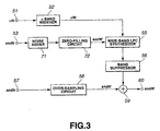
- FIG. 3 there is illustrated in the form of a schematic block diagram the second embodiment of the sound synthesizer according to the present invention.
- the sound synthesizer in FIG. 3 is also supplied at input terminals 57, 51 and 53 thereof with a narrow-band sound signal sndN whose frequency falls within a band of 300 to 3,400 Hz and sampling frequency is 8 kHz, a linear predictive factor ⁇ N used for synthesis of the narrow-band sound signal sndN, and an excitation source excN, respectively.
- the second embodiment is identical to the first embodiment in FIG. 1 except for the processing system for the narrow-band excitation source excN. Therefore the same or similar elements of the second embodiment as or to those in the first embodiment in FIG. 1 are indicated with the same or similar references and will not further be described.
- a noise signal of 3,400 to 4,000 Hz is generated separately by a noise adder 71 and added to the narrow-band excitation source excN, and then the noise-added excitation source excN is filled with zeros by a zero-filling circuit 72 to provide a wide-band excitation source excW. That is, the noise signal is added to the narrow-band excitation source excN, and then the wide-band excitation source excW is acquired to provide a wide-band sound signal.
- the frequency characteristic of the narrow-band excitation source excN is nearly flat.
- the narrow-band excitation source excN is not flat between 0 Hz and Nyquist frequency
- the excitation source excW band-widened by the zero-filling circuit 72 is not flat.
- the narrow-band excitation source is limited to a range of 300 to 3,400 Hz and a zero is inserted at every other samples to double the sampling frequency
- the wide-band excitation source excW ranges in frequency band from 300 to 3,400 Hz and from 4,600 to 7,700 Hz. Namely, there is a gap between the frequencies of 3,400 and 4,600 Hz. No quality sound can be acquired from a wide-band excitation source corresponding to this frequency gap.
- the noise adder 71 in the sound synthesizer in FIG. 3 generates a noise signal having a frequency band of 3,400 to 4,000 Hz, adjusts the gain of the noise signal, and adds the gain-adjusted noise to the excitation source excN.
- the signal gain is adjusted by determining a power of the narrow-band excitation and fitting the gain to the narrow-band excitation source power.
- a gain by which a noise code book is multiplied is given as a parameter in advance, if any, may be used as it is or a value corresponding to the parameter may be acquired without acquisition of any power of the excitation source.
- the zero-filling circuit 72 is provided to insert a zero value of n-1 between two successive samples when the sampling frequency of the wide-band sound is n times higher than that of the narrow-band sound.
- the sampling frequency is adjusted and an aliased component takes place.
- the frequency characteristic of the noise-added excitation source is originally nearly flat, the aliased signal is also flatter than the original signal. Therefore, the aliased signal is also nearly flat and can be used as a quality wide-band excitation source.
- the sound synthesizer When the sound synthesizer is supplied with the linear predictive factor ⁇ N from the input terminal 51, narrow-band excitation source excN from the input terminal 53 and the narrow-band sound signal sndN from the input terminal 57, first the frequency band of the narrow-band linear predictive factor ⁇ N is widened to provide the wide-band linear predictive factor ⁇ W.
- the narrow-band excitation source excN is band-widened by first adding the noise signal generated by the noised adder 71 to the band-widened excitation source excN and then filling the noise-added signal with zeros by the zero-filling circuit 72 to provide a quality wide-band excitation source excW.
- the wide-band LPC synthesizer 55 uses these signals to provide a first wide-band sound signal. Then, the frequency band of the narrow-band sound in the first wide-band sound signal is suppressed to provide a second wide-band sound signal.
- the narrow-band sound signal sndN is over-sampled by the over-sampling circuit 58 to the sampling frequency of the wide-band sound signal, and has the second wide-band sound signal added thereto by the adder 59 to provide a final wide-band sound signal sndW at the output terminal 60.
- the quality of the excitation source is improved to provide a quality wide-band signal.
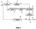
- FIG. 4 there is schematically illustrated in the form of a block diagram a third embodiment of the sound synthesizer according to the present invention.
- the sound synthesizer in FIG. 4 is also supplied at the input terminal 57 thereof with only a narrow-band sound signal sndN whose frequency falls within a band of 300 to 3,400 Hz and sampling frequency is 8 kHz.
- the third embodiment is identical to the first embodiment in FIG. 1 provided that an LPC analyzer 81 is provided to acquire the linear predictive factor ⁇ N and narrow-band excitation source excN. Therefore the same or similar elements of the third embodiment as or to those in the first embodiment in FIG. 1 are indicated with the same or similar references and will not further be described.
- the LPC analyzer 81 is provided for linear predictive analysis of the narrow-band sound sndN supplied from the input terminal 57 to provide a linear predictive factor ⁇ N and a linear prediction residual excN resulted from a reverse filtering using the linear predictive factor ⁇ N.
- the linear predictive factor ⁇ N and linear prediction residual excN provided from the LPC analyzer 81 are shaped directly or after being post-processed in some manner, and used as the linear predictive factor ⁇ N and excitation source excN in the first embodiment in FIG. 1 to widen the frequency band of a sound.
- the LPC analyzer 81 makes a linear predictive analysis of the sound signal sndN to provide the narrow-band linear predictive factor ⁇ N and narrow-band linear prediction residual excN.
- the frequency band of the narrow-band linear predictive factor ⁇ N is widened by the narrow-band linear predictive factor ( ⁇ ) band widener 52 to provide the wide-band linear predictive factor ⁇ W.
- the narrow-band excitation source excN is band-widened by first filling the narrow-band excitation source excN with zeros by the zero-filling circuit 61 and adding the noise signal generated by the noised adder 62 to the zero-filled narrow-band excitation source excN to provide a quality wide-band excitation source excW'.
- These signals are used in the wide-band LPC synthesizer 55 to provide a first wide-band sound signal. Then, the frequency band of the narrow-band sound in the first wide-band sound signal is suppressed to provide a second wide-band sound signal.
- the narrow-band sound signal sndN is over-sampled by the over-sampling circuit 58 to the sampling frequency of the wide-band sound signal, and has the second wide-band sound signal added thereto by the adder 59 to provide a final wide-band sound signal sndW at the output terminal 60.
- the quality of the excitation source is improved to provide a quality wide-band signal.
- FIG. 5 there is schematically illustrated in the form of a block diagram a fourth embodiment of the sound synthesizer according to the present invention.
- the sound synthesizer in FIG. 5 is also supplied at the input terminal 57 thereof with only a narrow-band sound signal sndN whose frequency falls within a band of 300 to 3,400 Hz and sampling frequency is 8 kHz.
- the fourth embodiment is identical to the third embodiment in FIG. 4 except for the processing system for the narrow-band excitation source excN acquired by means of an LPC analyzer 81. Therefore the same or similar elements of the fourth embodiment as or to those in the third embodiment in FIG. 1 are indicated with the same or similar references and will not further be described.
- a noise signal of 3,400 to 4,000 Hz is generated separately by the noise adder 71 and added to the linear predictive residual excN, and then the noise-added linear predictive residual excN is filled with zeros by the zero-filling circuit 72 to provide a wide-band excitation source excW. That is, the noise signal is added to the narrow-band linear predictive residual excN to provide the wide-band excitation source excW, thereby synthesizing a wide-band sound signal.
- the LPC analyzer 81 makes a linear predictive analysis of the sound signal sndN to provide the narrow-band linear predictive factor ⁇ N and narrow-band linear prediction residual excN.
- the band of the narrow-band linear predictive factor ⁇ N is widened by the narrow-band linear predictive factor band widener ( ⁇ band widener) 52 to provide the wide-band linear predictive factor ⁇ W.
- the narrow-band excitation source excN is band-widened by first adding the noise signal generated by the noise adder 71 to the narrow-band excitation source excN and then filling the noise-added narrow-band excitation source excN with zeros by the zero-filling circuit 72 to provide a quality wide-band excitation source excW'.
- These signals are used in the wide-band LPC synthesizer 55 to provide a first wide-band sound signal. Then, the frequency band of the narrow-band sound in the first wide-band sound signal is suppressed to provide a second wide-band sound signal.
- the narrow-band sound signal sndN is over-sampled by the over-sampling circuit 58 to the sampling frequency of the wide-band sound signal, and has the second wide-band sound signal added thereto by the adder 59 to provide a final wide-band sound signal sndW at the output terminal 60.
- the quality of the excitation source is improved to provide a quality wide-band signal.
- FIG. 6 there is schematically illustrated in the form of a block diagram a fifth embodiment of the sound synthesizer according to the present invention.
- the sound synthesizer in FIG. 6 is also supplied at the input terminal 1 thereof with only a narrow-band sound signal sndN whose frequency falls within a band of 300 to 3,400 Hz and sampling frequency is 8 kHz.
- the fifth embodiment of the sound synthesizer includes a wide-band voiced sound code book 12 and wide-band unvoiced sound code book 14, created in advance based on voiced and unvoiced sound parameters, respectively, extracted from wide-band voiced and unvoiced sounds, respectively, and a narrow-band voiced sound code book 7 and narrow-band unvoiced sound code book 10, created in advanced based on voiced and unvoiced sound parameters, respectively, extracted from a narrow-band voiced sound signal acquired by limiting the frequency band of the wide-band sound and having a frequency of 300 to 3,400 Hz.
- the fifth embodiment of the sound synthesizer also includes a framing circuit 2 to frame the narrow-band sound signal received at the input terminal 1 at every 160 samples (one frame lasts for 20 msec since the sampling frequency is 8 kHz), a zero-filling circuit 16 to form an excitation source based on the narrow-band sound signal framed by the framing circuit 2, a noise adder 91 to add a noise signal to the excitation source from the zero-filling circuit 16, a U/UV judging circuit 5 to determine whether the input narrow-band signal is a voiced sound (V) or an unvoiced sound (UV) at each frame of 20 msec, an LPC analyzer (linear predictive coding) 3 to provide a linear predictive factors ⁇ for narrow-band voiced sound or unvoiced sound based on the result of V/UV determination from the U/UV judging circuit 5, a linear predictive factor/autocorrelation ( ⁇ ) converter 4 to convert the linear predictive factor ⁇ from the LPC analyzer 3 to an autocorrelation ⁇ being a
- the sound synthesizer further includes an over-sampling circuit 19 to over-sample the sampling frequency of the narrow-band sound framed by the framing circuit 2 from 8 kHz to 16 kHz, a band-stop filter (BSF) 18 to remove from the synthetic output from the LPC synthesizer 17 a signal component of 300 to 3,400 Hz in the input narrow-band sound signal, and an adder 20 to add to the output from the BSF 18 the original narrow-band sound signal supplied from the over-sampling circuit 19 and whose sampling frequency is 16 kHz and frequency band is 300 to 3,400 Hz.
- the sound synthesizer delivers at an output terminal 21 thereof a digital sound signal whose frequency band is 300 to7,000 Hz and sampling frequency is 16 kHz.
- the wide-band voiced sound code book 12 and wide-band unvoiced sound code book 14 are created using voiced and unvoiced sound parameters extracted from wide-band voiced and unvoiced sounds (V and UV), respectively, in a wide-band sound signal having a frequency band of 300 to 7,000 Hz, for example, framed at every 20 msec as in the framing by the framing circuit 2.
- the narrow-band voiced sound code book 7 and wide-band unvoiced sound code book 10 are created using voiced and unvoiced sound parameters extracted from a narrow-band sound signal whose frequency band falls within a range of 300 to 3,400 Hz, for example, acquired by limiting the frequency band of the above wide-band sound.
- a wide-band learning sound signal is created, and framed at every 20 msec at step S1.
- the frequency band of the wide-band learning sound signal is limited at step S2 to provide a narrow-band sound signal.
- this narrow-band signal is also framed at the same timing as in the framing at step S1.
- values of frame energy, zero-cross, etc. are examined to judge whether the narrow-band sound is a voiced (V) or unvoiced (UV) sound at step S4.
- the wide-band sound signal frames are classified into V and UV lists.
- the narrow-band sound signal has been framed at the same timing as the wide-band sound signal.
- the wide-band frames acquired at the same time as the narrow-band V frames are taken as the wide-band V frames while those acquired at the same time as the narrow-band UV frames are taken as the wide-band UV frames.
- learning data are produced.
- the wide-band frames corresponding to the narrow-band frames having been classified into neither V nor UV frames are excluded.
- the learning data may be acquired by reversely following the above procedure (not shown). That is, the wide-band frames are first classified into V and UV ones, and then the narrow-band frames are classified into V and UV ones.
- the learning data are used to create the code books as shown in FIG. 8 showing a flow chart of operations effected to create the code books used in the fifth embodiment of the sound synthesizer in FIG. 8.
- the wide-band V (or UV) frames list is used to learn and generate a wide-band V (UV) code book.
- step S6 up to dn-the order autocorrelation parameters are extracted from each wide-band frame.
- Each of the autocorrelation parameters is computed using the following formula (1): where x is an input signal, ⁇ (xi) is an i-th order autocorrelation and N is a frame length.
- a dw-the order, sw-sized wide-band V (UV) code book is made by the GLA (General Lloyd Algorithm) from the dw-the order autocorrelation in each wide-band frame.
- FIG. 9 showing a flow chart-of operations effected to otherwise create the code books used in the sound synthesizer in FIG. 6. That is, a narrow-band code book is first learned and made at steps 9 and 10 using the narrow band frame parameter, and then the center of gravity of the wide-band frame parameter corresponding to the narrow-band frame parameter is determined at step S11.
- code books including the two narrow-band V and UV code books and two wide-band V and UV code books are made.
- FIG. 10 there is given a flow chart of operations of the sound synthesizer to which the sound synthesizing method according to the present invention is applied.
- the above code books are used to provide a wide-band sound signal when a narrow-band sound is entered to the sound synthesizer in practice.
- the narrow-band sound signal supplied from the input terminal 1 is framed at every 160 samples (20 msec) by the framing circuit 2 at step S21.
- Each of the frames thus formed is subjected to LPC analysis by the LPC analyzer 3 at step S23 and thus divided into linear predictive factor ( ⁇ ) parameter and LPC residual.
- the ⁇ parameter is convened to an autocorrelation ⁇ by the ⁇ convener 4 at step S24.
- V/UV judging circuit 5 It is judged by the V/UV judging circuit 5 at S22 whether the framed signal is judged to be V or UV.
- a switch 6 to select a destination of the output from the ⁇ converter 4 is connected to the narrow-band voiced sound quantizer 7.
- the switch 6 is connected to the narrow-band unvoiced sound quantizer 9.
- the voiced sound autocorrelation ⁇ from the switch 6 is supplied to the narrow-band V quantizer 7 and quantized using the narrow-band V code book 8 at step S25.
- the V/UV judging circuit 5 has judged a framed signal to V
- the unvoiced sound autocorrelation ⁇ from the switch 6 is supplied to the narrow-band UV quantizer 9 where it is quantized using the narrow-band UV code book 10 at step S25.
- the quantized framed signal is dequantized by the wide-band V dequantizer 11 or wide-band UV dequantizer 13 using the wide-band V code book 12 or wide-band UV code book 14 to provide a wide-band autocorrelation.
- the wide-band autocorrelation is convened to a wide-band linear predictive factor ⁇ by the ⁇ a convener 15 at step S27.
- the LPC residual from the LPC analyzer 3 is filled with a zero between samples thereof by the zero-filling circuit 16 and thus up-sampled, and band-widened by aliasing, at step S28.
- a noise signal is added to the wide-band excitation source by the noise adder 91 and then supplied to the LPC synthesizer 17.
- the wide-band linear predictive factor ⁇ and the noise-added wide-band excitation source are subjected to LPC synthesis in the LPC synthesizer 17 to provide a wide-band sound signal.
- the wide-band sound signal itself is only a wide-band signal acquired by prediction, and contains a prediction-caused error. Especially so long as the frequency range of the input narrow-band sound is concerned, the input sound should be used as it is.
- the frequency range of the input narrow-band sound is filtered out by the BSF 18 at step S30.
- the narrow-band sound is over-sampled by the over-sampling circuit 19 at step S31.
- the input narrow-band sound and the over-sampled narrow-band sound are added together at step S32 to provide a band-widened sound signal. Note that for the above addition, the gain may be adjusted and the high frequency band is somewhat suppressed to improve the audibility of the sound.
- the fifth embodiment is characterized in that in the noise adder 91, a noise signal having a frequency band of 3,400 to 4,600 Hz is generated, its gain is adjusted and the noise signal is added to the excitation source excW filled with zeros by the zero-filling circuit 16.
- the wide-band excitation source excW thus provided is flatter.
- the gain is adjusted by acquiring a power of the narrow-band excitation source or zero-filled excitation source, and fitting the gain to the power.
- a codec coder/decoder
- a gain by which a noise code book is multiplied is given as a parameter in advance, if any, may be used as it is or a value corresponding to the parameter may be acquired without acquisition of any power of the excitation source.
- the sound synthesizer shown in FIG. 6 can provide a quality wide-band sound signal by improving the quality of the excitation source.
- This sound synthesizer uses the autocorrelation parameters in the total of four code books but the present invention is not limited to the use of autocorrelation parameters.
- LPC ceptsrum may effectively be used.
- the ceptsrum envelope may be taken as a parameter.
- the aforementioned sound synthesizer uses the narrow-band V code book 8 and narrow-band UV code book 10.
- these code books 8 and 10 may not be used. In this case, the RAM capacity can be reduced for the code books.
- FIG. 11 shows the construction of the above variant of the sound synthesizer.
- this sound synthesizer uses, in place of the narrow-band V and UV code books 8 and 10, arithmetic circuits 25 and 26 to acquire narrow-band V and UV parameters by computing each code vector in the wide-band code book.
- the sound synthesizer is similar to the sound synthesizer in FIG. 6.
- ⁇ is an autocorrelation
- x n is a narrow-band signal
- x w is a wide-band signal
- h is an impulse response of the band stop filter (BSF).
- a narrow-band autocorrelation ⁇ (x n ) can be computed from a wide-band autocorrelation ⁇ (x w ). Therefore, only either of the wide- and narrow-band vectors is necessary.
- a narrow-band autocorrelation can be acquired by convolution of a wide-band autocorrelation and an autocorrelation of the impulse response of BSF.
- this sound synthesizer can operate as in FIG. 12, not as in FIG. 10.
- the narrow-band sound signal supplied from the input terminal 1 is first framed at every 160 samples (20 msec) by the framing circuit 2 at step S41.
- Each of the frames thus formed is subjected to LPC analysis by the LPC analyzer 3 at step S43 and thus divided into linear predictive factor ( ⁇ ) parameter and LPC residual.
- the ⁇ parameter is converted to an autocorrelation ⁇ by the ⁇ converter 4 at step S44.
- V/UV judging circuit 5 It is judged by the V/UV judging circuit 5 at step S42 whether the framed signal is judged to be V or UV.
- the switch 6 When it is determined to be V, the switch 6 to select a destination of the output from the ⁇ converter 4 is connected to the narrow-band voiced sound quantizer 7.
- the switch 6 When it is determined to be UV, the switch 6 is connected to the narrow-band unvoiced sound quantizer 9.
- the voiced sound autocorrelation ⁇ from the switch 6 is supplied to the narrow-band V quantizer 7 where it is quantized, at step S46.
- the narrow-band code book but the narrow-band V parameter acquired by the arithmetic circuit 25 at step S45 is used.
- the V/UV judging circuit 5 has judged a framed signal to V
- the unvoiced sound autocorrelation ⁇ from the switch 6 is supplied to and quantized by the narrow-band UV quantizer 9 at step S46.
- the narrow-band UV code book not the narrow-band UV parameter acquired by the arithmetic circuit 26 is used for this quantization.
- the quantized framed signal is dequantized by the wide-band V dequantizer 11 or wide-band UV dequantizer 13 using the wide-band V code book 12 or wide-band UV code book 14, respectively, to provide a wide-band autocorrelation.
- the wide-band autocorrelation is convened to a wide-band linear predictive factor ⁇ by the ⁇ converter 15 at step S48.
- the LPC residual from the LPC analyzer 3 is filled with a zero between two successive samples by the zero-filling circuit 116 and thus up-sampled, and band-widened by aliasing, at step S49.
- a noise signal is added to the wide-band excitation source by the noise adder 91 and then supplied to the LPC synthesizer 17.
- the wide-band linear predictive factor ⁇ and the noise-added wide-band excitation source are subjected to LPC synthesis in the LPC synthesizer 17 to provide a wide-band sound signal.
- the wide-band sound signal itself is only a wide-band signal acquired by prediction and contains a prediction-caused error. Especially so long as the frequency range of the input narrow-band sound is concerned, the input sound should be used as it is.
- the frequency range of the input narrow-band sound is filtered out by the BSF 18 at step S51.
- the narrow-band sound is over-sampled by the over-sampling circuit 19 at step S52.
- the input narrow-band sound and the over-sampled narrow-band sound are added together at step S53.
- the quantization is done not by comparison with the code vector of the narrow-band code books but by comparison with a code vector acquired by a computation using the wide-band code books.
- the wide-band code books can be used for both the analysis and synthesis, so the memory for holding the narrow-band code books becomes unnecessary.
- this sound synthesizer can also provide a quality wide-band sound signal by improving the quality of the excitation source.
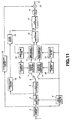
- the present invention proposes also a further variant of the sound synthesizer.
- the variant is shown in FIG. 13.
- a sound synthesizing method according to the present invention is applied in which there are used only the wide-band code books and the amount of computation remains not increased.
- the sound synthesizer uses, in place of the arithmetic circuits 25 and 26 in FIG. 11, partial extraction circuits 28 and 29 to provide narrow-band parameters by partially extracting each code vector in the wide-band code books.
- this variant is similar to the sound synthesizer shown in FIG. 6 or 11.
- the new filter given by the formula (4) has the same pass band and inhibition band as those of the aforementioned BSF and its attenuation characteristic is a square of that of the above BSF. Therefore, this new filter can also be said to be a band stop filter.
- the second-order autocorrelation in the actual voiced sound is smaller than the first-order one, and the third-order autocorrelation is further smaller that the second one, .... Namely, the autocorrelations will depict a monotonously descending curve.
- the narrow-band autocorrelation can theoretically be determined by passing the low frequency band of the narrow-band autocorrelation.
- the wide-band autocorrelation itself varies along a gentle slope, however, it will little change even when its low frequency band is passed. Omission of the low-frequency band passing will cause no influence on the wide-band autocorrelation. Therefore, the wide-band autocorrelation can be used as the narrow-band autocorrelation itself. However, since the sampling frequency of the wide-band signal is two times higher than that of the narrow-band signal, the narrow-band autocorrelation will be taken from the wide-band autocorrelation at every other orders of the latter in practice.
- the wide-band autocorrelation code vector taken at every other orders can be dealt with like the narrow-band autocorrelation code vector, and the input narrow-band sound autocorrelation can be quantized based on the wide-band code book.
- the narrow-band code book is unnecessary.
- the unvoiced sound has a large energy in the high frequency band thereof, so that if no correct prediction is possible, a large influence will result. Therefore, the input sound is normally determined to be V rather than UV and it is only when the probability that the input sound is UV that it is determined to be UV.
- the UV code book size is made smaller than the V code book and only UV vectors are definitely distinct from V vectors are registered in the UV code book.
- the UV autocorrelation does not depict so smooth a curve as the V autocorrelation
- comparison of the wide-band autocorrelation code vectors taken at every other orders with the input narrow-band signal autocorrelation enables an autocorrelation equivalent to that when the low frequency band of the wide-band autocorrelation code vector is passed, namely, when the narrow-band code book exists. That is, neither narrow-band V nor UV code book is necessary.
- the parameters used in the code book when taken as an autocorrelation, they can be quantized by comparing the autocorrelation of the input narrow-band sound with the wide-band code vectors taken at every other orders.
- This quantization can be implemented by allowing the partial extraction circuits 28 and 29 to take the wide-band code book vectors at every other orders at step S45 in FIG. 12.
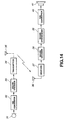
- This application is a digital portable telephone apparatus having at the receiver side the sound synthesizer adapted to synthesize using plural kinds of input coded parameters as shown in FIG. 14.
- the digital portable telephone apparatus is constructed as will be described below.
- the transmitter and receiver sections are provided separately from each other but actually housed together in one portable telephone apparatus.
- a sound signal supplied from a microphone 31 is converted to a digital signal by an A/D converter 32, coded by a sound encoder 33, processed to be an output bit by a transmitter 34 for transmission from an antenna 35.
- the sound encoder 33 supplies to the transmitter 34 coded parameters including an excitation source-related parameter, linear predictive factor ⁇ , etc. taking in consideration a band narrowing along the transmission path.
- a radio wave captured by the antenna 36 is received by a receiver 37, the above-mentioned coded parameters are decoded by a sound decoder 38, a sound is synthesized by a sound synthesizer 39 using the above decoded parameters, the synthesized sound is rendered to an analog sound signal by a D/A convener 40, and the analog sound signal is delivered at a speaker 41.
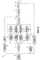
- the sound synthesizer shown in FIG. 15 is adapted to synthesize a sound using coded parameters sent from the sound encoder 33 in the transmitter section of the digital portable telephone apparatus.
- the coded parameters are decoded by the sound decoder 38 by reversely following the encoder procedure having been done in the sound encoder 33.
- the sound decoder 38 When the sound encoder 33 adopts the PSI (Pitch Synchronous Innovation)-CELP method for the parameter coding, the sound decoder 38 also adopts the PSI-CELP method.
- PSI Switch Synchronous Innovation
- the sound encoder 38 decodes a narrow-band excitation source from a excitation source-related parameter being a first one of the coded parameters and sends it to the zero-filling circuit 16.
- a linear predictive factor ⁇ being a second one of the coded parameters is supplied to the linear -predictive factor/autocorrelation ( ⁇ ) convener 4.
- a voiced/unvoiced (V/UV) sound judging flag being a third one of the coded parameters is supplied to the V/UV judging circuit 5.
- the sound synthesizer includes the sound encoder 38, zero-filling circuit 16, noise adder 91, ⁇ convener 4 and V/UV judging circuit 5, and in addition, the wide-band voiced and unvoiced sound code books 12 and 14 previously generated using the voiced and unvoiced sound parameters extracted from wide-band voiced and unvoiced sounds.
- the sound synthesizer includes the partial extraction circuits 28 and 29 to provide narrow-band parameters by partially extracting each code vector in the wide-band voiced and unvoiced sound code books 12 and 14, narrow-band voiced sound quantizer 7 to quantize the narrow-band voiced sound autocorrelation from the ⁇ convener 4 using the narrow-band parameter from the partial extraction circuit 28, narrow-band unvoiced sound quantizer 9 to quantize the narrow-band unvoiced autocorrelation from the ⁇ converter 4 using the narrow-band unvoiced parameter from the partial extraction circuit 29, wide-band voiced sound dequantizer 11 to dequantize the narrow-band voiced sound quantized data from the narrow-band voiced sound quantizer 7 using the wide-band voiced sound code book 12, wide-band unvoiced sound dequantizer 13 to dequantize the narrow-band unvoiced sound quantized data from the narrow-band unvoiced sound quantizer 9 using the wide-band unvoiced sound code book 14, autocorrelation/linear predictive factor ( ⁇ ) converter 15 to convert a wide-band voiced sound auto
- the sound synthesizer includes the over-sampling circuit 19 to over-sample the sampling frequency of the narrow-band sound decoded by the sound decoder 38 from 8 kHz to 16 kHz, band-stop filter (BSF) 18 to remove from the synthetic output from the LPC synthesizer 17 a signal component of 300 to 3,400 Hz in the input narrow-band sound signal, and an adder 20 to add to the output from the BSF 18 the original narrow-band sound signal supplied from the over-sampling circuit 19 and whose sampling frequency is 16 kHz and frequency band is 300 to 3,400 Hz.
- BSF band-stop filter
- the wide-band voiced and unvoiced sound code books 12 and 14 can be generated by following the procedures shown in FIGS. 7 to 9. For a quality code book, only sounds which are positively V and those which are surely UV are taken as learning data while sounds in transition from V to UV or from UV to V and those not easily determinable to be V or UV are excluded. Thus, a narrow-band learning V frames list and a narrow-band learning UV frames list are acquired.
- the linear predictive factor a decoded by the sound decoder 38 is convened to the autocorrelation ⁇ by the ⁇ converter 4 at step S61.
- the parameter concerning the voiced/unvoiced sound judging flag decoded by the sound decoder 38 is decoded by the V/UV judging circuit 5 at step S62 to judge whether the sound is a voiced (V) or unvoiced (UV) sound.
- the switch 6 When it is determined to be V, the switch 6 to select a destination of the output from the ⁇ convener 4 is connected to the narrow-band voiced sound quantizer 7. When it is determined to be UV, the switch 6 is connected to the narrow-band unvoiced sound quantizer 9.
- V/UV judgment is different from that effected for the code book generation and the frame signal is always judged to be either V or UV.
- the voiced sound autocorrelation ⁇ from the switch 6 is supplied to and quantized by the narrow-band V quantizer 7 at step S64.
- the narrow-band code book there is used in this quantization no narrow-band code book but the narrow-band parameter having been acquired by means of the partial extraction circuit 28 at step S63.
- the V/UV judging circuit 5 has judged the sound signal to V
- the unvoiced sound autocorrelation ⁇ from the switch 6 is supplied to and quantized by the narrow-band UV quantizer 9 at step 63. Also in this quantization, no narrow-band UV code book is used but the narrow-band UV parameter having been acquired by means of the partial extraction circuit 29 to quantize the sound signal.
- the quantized data is dequantized by the wide-band V dequantizer 11 or wide-band UV dequantizer 13 using the wide-band V code book 12 or wide-band UV code book 14 to provide a wide-band autocorrelation.
- the wide-band autocorrelation is converted to a wide-band linear predictive factor ⁇ by the ⁇ converter 15 at step S66.
- the excitation source-related parameter from the sound decoder 38 is filled with a zero between samples by the zero-filling circuit 16 and thus up-sampled, and band-widened by aliasing, at step S67.
- a noise signal is added to the wide-band excitation source by the noise adder 91 and then supplied to the LPC synthesizer 17.
- the wide-band linear predictive factor ⁇ and the wide-band excitation source are subjected to LPC synthesis in the LPC synthesizer 17 to provide a wide-band sound signal.
- the wide-band sound signal itself is only a wide-band signal acquired by prediction and contains a prediction-caused error. Especially so long as the frequency range of the input narrow-band sound is concerned, the input sound should be used as it is.
- the frequency range of the input narrow-band sound is filtered out by the BSF 18 at step S69. Then, the resulted data and over-sampled coded data from the over-sampling circuit 19 at step S70 are added together at step S71.
- the quantization is not effected by comparison with the narrow-band code book code vector but by comparison with the code vector acquired by partial extraction from the wide-band code book.
- the parameter ⁇ can be obtained during decoding. It is convened to a narrow-band autocorrelation, compared with a wide-band code book code vector taken at every other orders and thus quantized. In this sound synthesizer, the dequantization is done using all the same code vectors to provide a wide-band autocorrelation. The wide-band autocorrelation is convened to a wide-band linear predictive factor ⁇ . At this time, the gain adjustment and some wide-band suppression are also done as having been described to improve the sound quality.
- the wide-band code book is used for both the analysis and synthesis, so that the memory for holding the narrow-band code book is not required.
- a noise signal having a frequency band of 3,400 to 4,600 Hz is generated by the noise adder 91, adjusted in gain, and added to an excitation source excW having been filled with zeros at the zero-filling circuit 16.
- the wide-band excitation source thus obtained is flatter to provide a quality wide-band sound signal.
- the sound synthesizer adopting the PSI-CELP to synthesize a sound using the coded parameters from the sound decoder 38 may be a one shown in FIG. 17. As shown, this sound synthesizer uses in place of the partial extraction circuits 28 and 29 arithmetic circuits 25 and 26 to provide narrow-band V (UV) parameters by calculating each code vector in the wide-band code book. This sound synthesizer is identical to the one shown in FIG. 15 in other respects.
- FIG. 18 A second embodiment of the sound synthesizer used in the digital portable telephone apparatus is shown in FIG. 18. Since this embodiment of the sound synthesizer is also adapted to synthesize a sound using the coded parameters sent from the sound encoder 33 of the transmitter sector in the digital portable telephone apparatus, the sound decoder 46 reversely effects the ending having been effected by the sound encoder 33.
- the decoding by the sound decoder 46 is also based on the VSELP.
- the sound decoder 46 supplies an excitation source selector 47 with a parameter related to an excitation source being a first one of the coded parameters, the liner predictive factor/autocorrelation ( ⁇ - ⁇ ) converter 4 with a linear predictive factor ⁇ being a second one of the coded parameters, and the V/UV judging circuit 5 with a voiced/unvoiced sound judging flag being a third one of the coded parameters.
- This sound synthesizer is identical to those shown in FIGS. 15 and 17 and adopting the PSI-CELP provided that the excitation source selector 47 is provided upstream of the zero-filling circuit 16.
- the codec processes the voiced sound among others so that the voiced sound is smoothly audible.
- the VSELP type sound synthesizer has not this feature, so that when the bandwidth is increased, the voiced sound will be audible as if it included some noise.
- the excitation source selector 47 works as will be described below with reference to FIG. 19.
- the excitation source in the VSELP type synthesizer is generated as beta*bL[i]+gamma]*c1[i] where the beta is a long-term predictive factor, bL[i] is a gain and the cl[i] is an excitation code vector.
- the beta*bL[i] is a pitch component and the gamma1*c1[i] is a noise component.
- the energy of the beta*bL[i] is determined to be larger than that of the gamma1*c1[i] for a fixed length of time, the input sound is considered to a voiced sound having a strong pitch. So, the operations goes to YES at step S88.
- the excitation source is a train of pulses.
- the operation goes to NO, and the input sound is suppressed to zero.
- This input sound is filled with zeros at step S89.
- the VSELP type sound synthesizer no noise is added to the. If the beta*bL[i] is determined not to be larger than that of the gamma1*c1[i] at step S87, a sound is synthesized from a sample value of 1 and a one of 2. After the synthesized sound is filled with zeros at step S94, a noise is added to it at step S95. Thereafter, an LPC synthesis is effected at step S90. Thus, the voiced sound synthesized by the VSELP type sound synthesizer can be heard better.
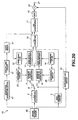
- VSELP type sound synthesizer to synthesize a sound using coded parameters from the sound decoder 46 may be a one shown in FIG. 20.
- the sound synthesizer shown in FIG. 20 uses in place of the partial extraction circuits 28 and 29 arithmetic circuits 25 and 26 to compute narrow-band voiced and unvoiced parameters from code vectors in the wide-band code book. This sound synthesizer is identical to the one shown in FIG. 18 in other respects.
- a sound can be synthesized using the narrow-band voiced sound code book 12 and wide-band unvoiced sound code book 14 previously generated using voiced and unvoiced parameters extracted from a wide-band voiced and unvoiced sound as shown in Fig. 6, and the narrow-band voiced and unvoiced sound code books 7 and 10 previously generated using voiced and unvoiced parameters extracted from a narrow-band sound signal having a frequency band of 300 to 3,400 Hz and having been acquired by limiting the frequency band of the wide-band sound.
- the present invention is not limited to a sound synthesizer adapted to predict a high frequency band from a low one.
- the means for predicting the wide-band spectrum is also applicable to an other signal than a sound.
- the present invention may not use only the linear predictive analysis but also the PARCOR analysis.
- the sound synthesizing method according to the present invention may be implemented by a computer program.
- the computer program may be loaded into a computer system, such as a personal computer or a telephone or any other apparatus incorporating a computer system. By subsequently executing the program, the computer system performs the method.
- the program may be stored on a storage medium such as the computer memory or a recording medium such as a CD-ROM to allow distribution of the program.
- the program may also be distributed electronically.
- FIG. 21 shows an embodiment of such a personal computer implementing the present invention.
- the personal computer includes a ROM (read-only memory) 101 in which the sound synthesizing method configured as a sound synthesis program is stored, and a CPU (central processing unit) 102 which recalls the sound synthesis program from the ROM 101 and executes it.
- ROM read-only memory
- CPU central processing unit
- the personal computer further includes a RAM (random access memory) 103 in which programs and data required for operation of the CPU 102 are stored, an input device 104 consisting of a microphone, external interface, etc. for example, and an output device 105 consisting of a display device, speaker, etc. for example to output necessary information.
- a RAM random access memory
Applications Claiming Priority (2)
| Application Number | Priority Date | Filing Date | Title |
|---|---|---|---|
| JP11115415A JP2000305599A (ja) | 1999-04-22 | 1999-04-22 | 音声合成装置及び方法、電話装置並びにプログラム提供媒体 |
| JP11541599 | 1999-04-22 |
Publications (2)
| Publication Number | Publication Date |
|---|---|
| EP1047045A2 true EP1047045A2 (fr) | 2000-10-25 |
| EP1047045A3 EP1047045A3 (fr) | 2001-03-21 |
Family
ID=14662017
Family Applications (1)
| Application Number | Title | Priority Date | Filing Date |
|---|---|---|---|
| EP00303303A Withdrawn EP1047045A3 (fr) | 1999-04-22 | 2000-04-19 | Matériel sain etméthode de synthesisation |
Country Status (6)
| Country | Link |
|---|---|
| US (1) | US6732075B1 (fr) |
| EP (1) | EP1047045A3 (fr) |
| JP (1) | JP2000305599A (fr) |
| KR (1) | KR20000077057A (fr) |
| CN (1) | CN1185620C (fr) |
| TW (1) | TW469421B (fr) |
Cited By (3)
| Publication number | Priority date | Publication date | Assignee | Title |
|---|---|---|---|---|
| WO2003044777A1 (fr) * | 2001-11-23 | 2003-05-30 | Koninklijke Philips Electronics N.V. | Extension de largeur de bande de signal audio |
| EP1482482A1 (fr) * | 2003-05-27 | 2004-12-01 | Siemens Aktiengesellschaft | Elargissement en frequence pour synthetiseur |
| US7978771B2 (en) | 2005-05-11 | 2011-07-12 | Panasonic Corporation | Encoder, decoder, and their methods |
Families Citing this family (23)
| Publication number | Priority date | Publication date | Assignee | Title |
|---|---|---|---|---|
| FI119576B (fi) * | 2000-03-07 | 2008-12-31 | Nokia Corp | Puheenkäsittelylaite ja menetelmä puheen käsittelemiseksi, sekä digitaalinen radiopuhelin |
| KR100711989B1 (ko) * | 2002-03-12 | 2007-05-02 | 노키아 코포레이션 | 효율적으로 개선된 스케일러블 오디오 부호화 |
| ATE335312T1 (de) * | 2002-05-27 | 2006-08-15 | Ericsson Telefon Ab L M | Farb-störungsidentifikation |
| JP3879922B2 (ja) * | 2002-09-12 | 2007-02-14 | ソニー株式会社 | 信号処理システム、信号処理装置および方法、記録媒体、並びにプログラム |
| JP4041385B2 (ja) * | 2002-11-29 | 2008-01-30 | 株式会社ケンウッド | 信号補間装置、信号補間方法及びプログラム |
| EP1431958B1 (fr) | 2002-12-16 | 2018-07-18 | Sony Mobile Communications Inc. | Un appareil connectable ou comportant un dispositif de génération de la parole, et programme d'ordinateur adapté |
| WO2004090870A1 (fr) | 2003-04-04 | 2004-10-21 | Kabushiki Kaisha Toshiba | Procede et dispositif pour le codage ou le decodage de signaux audio large bande |
| JP4580622B2 (ja) * | 2003-04-04 | 2010-11-17 | 株式会社東芝 | 広帯域音声符号化方法及び広帯域音声符号化装置 |
| WO2006075663A1 (fr) * | 2005-01-14 | 2006-07-20 | Matsushita Electric Industrial Co., Ltd. | Dispositif et procede de commutation audio |
| KR100724736B1 (ko) * | 2006-01-26 | 2007-06-04 | 삼성전자주식회사 | 스펙트럴 자기상관치를 이용한 피치 검출 방법 및 피치검출 장치 |
| US20090281813A1 (en) * | 2006-06-29 | 2009-11-12 | Nxp B.V. | Noise synthesis |
| US8688441B2 (en) * | 2007-11-29 | 2014-04-01 | Motorola Mobility Llc | Method and apparatus to facilitate provision and use of an energy value to determine a spectral envelope shape for out-of-signal bandwidth content |
| US8433582B2 (en) * | 2008-02-01 | 2013-04-30 | Motorola Mobility Llc | Method and apparatus for estimating high-band energy in a bandwidth extension system |
| US20090201983A1 (en) * | 2008-02-07 | 2009-08-13 | Motorola, Inc. | Method and apparatus for estimating high-band energy in a bandwidth extension system |
| JP5326311B2 (ja) * | 2008-03-19 | 2013-10-30 | 沖電気工業株式会社 | 音声帯域拡張装置、方法及びプログラム、並びに、音声通信装置 |
| US8463412B2 (en) * | 2008-08-21 | 2013-06-11 | Motorola Mobility Llc | Method and apparatus to facilitate determining signal bounding frequencies |
| US8463599B2 (en) * | 2009-02-04 | 2013-06-11 | Motorola Mobility Llc | Bandwidth extension method and apparatus for a modified discrete cosine transform audio coder |
| JP5002642B2 (ja) * | 2009-11-09 | 2012-08-15 | 株式会社東芝 | 広帯域音声符号化方法及び広帯域音声符号化装置 |
| CN102063905A (zh) * | 2009-11-13 | 2011-05-18 | 数维科技(北京)有限公司 | 一种用于音频解码的盲噪声填充方法及其装置 |
| JP5443547B2 (ja) * | 2012-06-27 | 2014-03-19 | 株式会社東芝 | 信号処理装置 |
| CN104301064B (zh) | 2013-07-16 | 2018-05-04 | 华为技术有限公司 | 处理丢失帧的方法和解码器 |
| CN106683681B (zh) * | 2014-06-25 | 2020-09-25 | 华为技术有限公司 | 处理丢失帧的方法和装置 |
| JP6611042B2 (ja) * | 2015-12-02 | 2019-11-27 | パナソニックIpマネジメント株式会社 | 音声信号復号装置及び音声信号復号方法 |
Family Cites Families (9)
| Publication number | Priority date | Publication date | Assignee | Title |
|---|---|---|---|---|
| TW224191B (fr) * | 1992-01-28 | 1994-05-21 | Qualcomm Inc | |
| US5765127A (en) * | 1992-03-18 | 1998-06-09 | Sony Corp | High efficiency encoding method |
| JP3343965B2 (ja) * | 1992-10-31 | 2002-11-11 | ソニー株式会社 | 音声符号化方法及び復号化方法 |
| US5502713A (en) * | 1993-12-07 | 1996-03-26 | Telefonaktiebolaget Lm Ericsson | Soft error concealment in a TDMA radio system |
| JP3747492B2 (ja) * | 1995-06-20 | 2006-02-22 | ソニー株式会社 | 音声信号の再生方法及び再生装置 |
| JP3653826B2 (ja) * | 1995-10-26 | 2005-06-02 | ソニー株式会社 | 音声復号化方法及び装置 |
| JP4005154B2 (ja) * | 1995-10-26 | 2007-11-07 | ソニー株式会社 | 音声復号化方法及び装置 |
| JP3335841B2 (ja) * | 1996-05-27 | 2002-10-21 | 日本電気株式会社 | 信号符号化装置 |
| JPH1091194A (ja) * | 1996-09-18 | 1998-04-10 | Sony Corp | 音声復号化方法及び装置 |
-
1999
- 1999-04-22 JP JP11115415A patent/JP2000305599A/ja not_active Withdrawn
-
2000
- 2000-04-17 TW TW089107180A patent/TW469421B/zh not_active IP Right Cessation
- 2000-04-19 EP EP00303303A patent/EP1047045A3/fr not_active Withdrawn
- 2000-04-20 US US09/556,036 patent/US6732075B1/en not_active Expired - Fee Related
- 2000-04-20 KR KR1020000021084A patent/KR20000077057A/ko not_active Application Discontinuation
- 2000-04-22 CN CNB001188240A patent/CN1185620C/zh not_active Expired - Fee Related
Non-Patent Citations (2)
| Title |
|---|
| SCHNITZLER J.: "A 13.0 kbit/s wideband speech codec based on SB-ACELP", PROCEEDINGS OF THE IEEE INTERNATIONAL CONFERENCE ON ACOUSTICS, SPEECH AND SIGNAL PROCESSING, 12 May 1998 (1998-05-12), SEATTLE, WA, USA, pages 157 - 160 * |
| YASUKAWA H.: "Quality Enhancement of Band Limited Speech by Filtering and Multirate Techniques", INTERNATIONAL CONFERENCE ON SPOKEN LANGUAGE PROCESSING, 18 September 1994 (1994-09-18), YOKOHAMA, JAPAN, pages 1607 - 1610 * |
Cited By (4)
| Publication number | Priority date | Publication date | Assignee | Title |
|---|---|---|---|---|
| WO2003044777A1 (fr) * | 2001-11-23 | 2003-05-30 | Koninklijke Philips Electronics N.V. | Extension de largeur de bande de signal audio |
| EP1482482A1 (fr) * | 2003-05-27 | 2004-12-01 | Siemens Aktiengesellschaft | Elargissement en frequence pour synthetiseur |
| US7630780B2 (en) | 2003-05-27 | 2009-12-08 | Palm, Inc. | Frequency expansion for synthesizer |
| US7978771B2 (en) | 2005-05-11 | 2011-07-12 | Panasonic Corporation | Encoder, decoder, and their methods |
Also Published As
| Publication number | Publication date |
|---|---|
| US6732075B1 (en) | 2004-05-04 |
| KR20000077057A (ko) | 2000-12-26 |
| TW469421B (en) | 2001-12-21 |
| JP2000305599A (ja) | 2000-11-02 |
| CN1185620C (zh) | 2005-01-19 |
| CN1274146A (zh) | 2000-11-22 |
| EP1047045A3 (fr) | 2001-03-21 |
Similar Documents
| Publication | Publication Date | Title |
|---|---|---|
| EP1047045A2 (fr) | Matériel sain etméthode de synthesisation | |
| EP0911807B1 (fr) | Procédé et dispositif de synthèse de la parole et d'expansion de bande passante des sons | |
| JP3592473B2 (ja) | 周波数領域内のlpc予測による時間領域内での知覚ノイズ整形 | |
| CN101180676B (zh) | 用于谱包络表示的向量量化的方法和设备 | |
| CA2347667C (fr) | Amelioration de la periodicite dans le decodage de signaux a large bande | |
| JP3881943B2 (ja) | 音響符号化装置及び音響符号化方法 | |
| US9767810B2 (en) | Packet loss concealment for speech coding | |
| CA2399706C (fr) | Reduction du bruit de fond dans des systemes de codage vocal sinusoidaux | |
| RU2584463C2 (ru) | Кодирование звука с малой задержкой, содержащее чередующиеся предсказательное кодирование и кодирование с преобразованием | |
| US20060122828A1 (en) | Highband speech coding apparatus and method for wideband speech coding system | |
| JP2010538317A (ja) | ノイズ補充の方法及び装置 | |
| JP2004310088A (ja) | 半レート・ボコーダ | |
| EP3511935A1 (fr) | Procédés, codeur et décodeur pour le codage et le décodage prédictifs linéaires de signaux sonores lors de la transition entre des trames possédant des taux d'échantillonnage différents | |
| US5913187A (en) | Nonlinear filter for noise suppression in linear prediction speech processing devices | |
| FI97580C (fi) | Rajoitetun stokastisen herätteen koodaus | |
| EP3175443B1 (fr) | Détermination d'un budget de codage d'une trame de transition lpd/fd | |
| US20080255860A1 (en) | Audio decoding apparatus and decoding method | |
| US8473286B2 (en) | Noise feedback coding system and method for providing generalized noise shaping within a simple filter structure | |
| KR102099293B1 (ko) | 오디오 인코더 및 오디오 신호를 인코딩하는 방법 | |
| US6801887B1 (en) | Speech coding exploiting the power ratio of different speech signal components | |
| JP4721355B2 (ja) | 符号化データの符号化則変換方法および装置 | |
| JP3598111B2 (ja) | 広帯域音声復元装置 | |
| KR100221186B1 (ko) | 음성 부호화 및 복호화 장치와 그 방법 | |
| JP3560964B2 (ja) | 広帯域音声復元装置及び広帯域音声復元方法及び音声伝送システム及び音声伝送方法 | |
| JP2004046238A (ja) | 広帯域音声復元装置及び広帯域音声復元方法 |
Legal Events
| Date | Code | Title | Description |
|---|---|---|---|
| PUAI | Public reference made under article 153(3) epc to a published international application that has entered the european phase |
Free format text: ORIGINAL CODE: 0009012 |
|
| AK | Designated contracting states |
Kind code of ref document: A2 Designated state(s): DE FR GB |
|
| AX | Request for extension of the european patent |
Free format text: AL;LT;LV;MK;RO;SI |
|
| PUAL | Search report despatched |
Free format text: ORIGINAL CODE: 0009013 |
|
| RIC1 | Information provided on ipc code assigned before grant |
Free format text: 7G 10L 13/00 A, 7G 10L 13/08 B, 7G 10L 21/02 B |
|
| AK | Designated contracting states |
Kind code of ref document: A3 Designated state(s): AT BE CH CY DE DK ES FI FR GB GR IE IT LI LU MC NL PT SE |
|
| AX | Request for extension of the european patent |
Free format text: AL;LT;LV;MK;RO;SI |
|
| 17P | Request for examination filed |
Effective date: 20010823 |
|
| AKX | Designation fees paid |
Free format text: DE FR GB |
|
| 17Q | First examination report despatched |
Effective date: 20030716 |
|
| STAA | Information on the status of an ep patent application or granted ep patent |
Free format text: STATUS: THE APPLICATION IS DEEMED TO BE WITHDRAWN |
|
| 18D | Application deemed to be withdrawn |
Effective date: 20040127 |