EP1046830B1 - Hydraulic power transmission joint - Google Patents
Hydraulic power transmission joint Download PDFInfo
- Publication number
- EP1046830B1 EP1046830B1 EP00107878A EP00107878A EP1046830B1 EP 1046830 B1 EP1046830 B1 EP 1046830B1 EP 00107878 A EP00107878 A EP 00107878A EP 00107878 A EP00107878 A EP 00107878A EP 1046830 B1 EP1046830 B1 EP 1046830B1
- Authority
- EP
- European Patent Office
- Prior art keywords
- center
- weight member
- spring
- torque characteristic
- torque
- Prior art date
- Legal status (The legal status is an assumption and is not a legal conclusion. Google has not performed a legal analysis and makes no representation as to the accuracy of the status listed.)
- Expired - Lifetime
Links
- 230000004308 accommodation Effects 0.000 claims description 42
- 230000007246 mechanism Effects 0.000 claims description 38
- 230000005540 biological transmission Effects 0.000 claims description 33
- 230000004044 response Effects 0.000 claims description 10
- 230000009471 action Effects 0.000 claims description 7
- 230000005484 gravity Effects 0.000 claims description 7
- 239000011435 rock Substances 0.000 claims description 6
- 230000000903 blocking effect Effects 0.000 claims description 5
- 230000008859 change Effects 0.000 claims description 4
- 230000009467 reduction Effects 0.000 description 9
- 230000006399 behavior Effects 0.000 description 5
- 238000010586 diagram Methods 0.000 description 3
- 238000006243 chemical reaction Methods 0.000 description 2
- 239000000446 fuel Substances 0.000 description 2
- 230000002093 peripheral effect Effects 0.000 description 2
- 230000001133 acceleration Effects 0.000 description 1
- 230000002411 adverse Effects 0.000 description 1
- 230000021615 conjugation Effects 0.000 description 1
- 230000008878 coupling Effects 0.000 description 1
- 238000010168 coupling process Methods 0.000 description 1
- 238000005859 coupling reaction Methods 0.000 description 1
- 230000007812 deficiency Effects 0.000 description 1
- 238000009877 rendering Methods 0.000 description 1
- XLYOFNOQVPJJNP-UHFFFAOYSA-N water Substances O XLYOFNOQVPJJNP-UHFFFAOYSA-N 0.000 description 1
Images

Classifications
-
- B—PERFORMING OPERATIONS; TRANSPORTING
- B60—VEHICLES IN GENERAL
- B60K—ARRANGEMENT OR MOUNTING OF PROPULSION UNITS OR OF TRANSMISSIONS IN VEHICLES; ARRANGEMENT OR MOUNTING OF PLURAL DIVERSE PRIME-MOVERS IN VEHICLES; AUXILIARY DRIVES FOR VEHICLES; INSTRUMENTATION OR DASHBOARDS FOR VEHICLES; ARRANGEMENTS IN CONNECTION WITH COOLING, AIR INTAKE, GAS EXHAUST OR FUEL SUPPLY OF PROPULSION UNITS IN VEHICLES
- B60K17/00—Arrangement or mounting of transmissions in vehicles
- B60K17/34—Arrangement or mounting of transmissions in vehicles for driving both front and rear wheels, e.g. four wheel drive vehicles
- B60K17/348—Arrangement or mounting of transmissions in vehicles for driving both front and rear wheels, e.g. four wheel drive vehicles having differential means for driving one set of wheels, e.g. the front, at one speed and the other set, e.g. the rear, at a different speed
- B60K17/35—Arrangement or mounting of transmissions in vehicles for driving both front and rear wheels, e.g. four wheel drive vehicles having differential means for driving one set of wheels, e.g. the front, at one speed and the other set, e.g. the rear, at a different speed including arrangements for suppressing or influencing the power transfer, e.g. viscous clutches
- B60K17/3505—Arrangement or mounting of transmissions in vehicles for driving both front and rear wheels, e.g. four wheel drive vehicles having differential means for driving one set of wheels, e.g. the front, at one speed and the other set, e.g. the rear, at a different speed including arrangements for suppressing or influencing the power transfer, e.g. viscous clutches with self-actuated means, e.g. by difference of speed
-
- F—MECHANICAL ENGINEERING; LIGHTING; HEATING; WEAPONS; BLASTING
- F16—ENGINEERING ELEMENTS AND UNITS; GENERAL MEASURES FOR PRODUCING AND MAINTAINING EFFECTIVE FUNCTIONING OF MACHINES OR INSTALLATIONS; THERMAL INSULATION IN GENERAL
- F16D—COUPLINGS FOR TRANSMITTING ROTATION; CLUTCHES; BRAKES
- F16D31/00—Fluid couplings or clutches with pumping sets of the volumetric type, i.e. in the case of liquid passing a predetermined volume per revolution
- F16D31/02—Fluid couplings or clutches with pumping sets of the volumetric type, i.e. in the case of liquid passing a predetermined volume per revolution using pumps with pistons or plungers working in cylinders
-
- F—MECHANICAL ENGINEERING; LIGHTING; HEATING; WEAPONS; BLASTING
- F16—ENGINEERING ELEMENTS AND UNITS; GENERAL MEASURES FOR PRODUCING AND MAINTAINING EFFECTIVE FUNCTIONING OF MACHINES OR INSTALLATIONS; THERMAL INSULATION IN GENERAL
- F16D—COUPLINGS FOR TRANSMITTING ROTATION; CLUTCHES; BRAKES
- F16D43/00—Automatic clutches
- F16D43/28—Automatic clutches actuated by fluid pressure
- F16D43/284—Automatic clutches actuated by fluid pressure controlled by angular speed
Definitions
- the present invention relates generally to a hydraulic power transmission joint for use in distribution of the driving force of a motor vehicle, and more particularly to a hydraulic power transmission joint capable of changing over the torque transmission characteristics in response to rotational-speed differences between two power shafts through the coupling thereof.
- the hydraulic power transmission joint comprises:
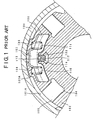
- FIG. 1 is a partial sectional view of a rotary valve of the hydraulic power transmission joint provided with the torque characteristic shifting mechanism.
- a rotary valve 102 is rotatably housed in a cam housing 101.
- the rotary valve 102 has on its outer periphery a positioning protrusion 102A which engages with a notch 101A formed in the inner periphery of the cam housing 101.
- the rotary valve 102 is provided with discharge ports 103 and intake ports 104 which are formed alternately in the circumferential direction, with the intake ports 104 leading to intake passages 104 extending to the outer peripheral surface of the rotary valve 102.
- An accommodation hole 106 is formed at the outer periphery of the rotary valve 102 outside the discharge ports 104.
- the accommodation hole 106 is in the shape of a circumferentially elongated hole having a raised portion formed on its bottom.
- the accommodation hole 106 accommodates a weight member 107 in such a manner as to be displaceable in the radial direction (centrifugal direction).
- the weight member 107 has a bottom which is shaped so as to correspond to the bottom of the accommodation hole 106 and which is provided with a recessed portion.
- the top of the weight member 107 is provided with spring accommodation holes 110 and 111 accommodating therein springs 108 and 109, respectively.
- a drain hole 112 is interposed between the accommodation hole 106 and the discharge port 103 so that the accommodation hole 106 and the discharge port 133 can communicate with each other by way of the drain hole 112.
- the drain hole 112 has at its exit an accommodation groove 114 for receiving a ball 113.
- the ball 113 is received in the accommodation groove 114 and normally blocks the drain hole 112.
- a predetermined gap is formed between the weight member 107 and the accommodation hole 106.
- the springs 108 and 109 press the weight member 107 by a given spring force.
- the ball 113 received in the accommodation groove 114 formed at the exit of the drain hole 112 blocks the drain hole 112 by the spring force of the springs 108 and 109, and when a predetermined vehicle velocity is reached and the weight member 107 is displaced in the centrifugal direction by the centrifugal force, the ball 113 opens the drain hole 112.
- the conventional torque characteristic shifting mechanism allows the weight member 107 to be displaced against the springs 108 and 109 in response to the vehicle velocity (centrifugal force) so that the ball 113 opens the drain hole 112 to relieve the internal pressure, thereby rendering the torque ⁇ T variable as seen in FIG. 2.
- a curve a represents a torque characteristic obtained when the vehicle velocity V has reached a predetermined vehicle velocity
- a curve b represents a torque characteristic obtained when the vehicle velocity V has reached a predetermined vehicle velocity V2.
- the transmission torque lowers depending on the vehicle velocity V as indicated by an arrow c, thereby preventing the running resistance from increasing.
- the spring force has also to be increased. Due to the relationship that the spring force balances directly with the area of contact A, however, larger spring accommodation spaces are needed, resulting in the joint having a larger external diameter.
- the amount of torque reduction is apt to become larger after the torque shifting, which may adversely affect the variances in vehicle behaviors.
- a hydraulic power transmission joint capable of remarkably reducing the spring accommodation space to achieve a reduction in dimensions of a joint and capable of preventing any variances in the vehicle behaviors.
- the hydraulic power transmission joint of the present invention transmits torque in response to a rotational-speed difference between the input and output shafts capable of relative rotations.
- the input and output shafts are front and rear shafts of a motor vehicle equipped with tires having different diameters and the joint serves to transmit torque in response to the rotational-speed difference between the front and rear shafts which increases accordingly as the vehicle velocity increases.
- the subject of the present invention is a hydraulic power transmission joint which transmits torque in response to a rotational-speed difference between the two shafts, the joint comprising:
- the present invention is characterized in that such a hydraulic power transmission joint further comprises a torque characteristic shifting mechanism for changing over the torque transmission characteristics in a stepwise manner depending on a rotational-speed difference between the two shafts.
- the torque characteristic shifting mechanism includes:
- the torque characteristic shifting mechanism may set the distances so as to meet a relationship R3 ⁇ R2 > R1 or R2 > R3 > R1 where R1, R2 and R3 are the distance from the center of rotation to a center of the ball, the distance from the center of rotation to a center of gravity of the weight member and the distance from the center of rotation to a center of the spring, respectively.
- the hydraulic power transmission joint of the present invention may comprise a plurality of torque characteristic shifting mechanisms each consisting of the accommodation hole, the weight member, the drain hole, the ball and the spring, so as to change over torque transmission characteristics at three or more steps in response to a rotational-speed difference between the two shafts.
- the hydraulic power transmission joint of the present invention may comprise a first torque characteristic shifting mechanism consisting of a first accommodation hole, a first weight member, a first drain hole, a first ball and a first spring; and a second torque characteristic shifting mechanism consisting of a second accommodation hole, a second weight member, a second drain hole, a second ball and a second spring, and wherein the first torque characteristic shifting mechanism sets a first rotational-speed difference (corresponding to the vehicle velocity V1) at which the torque characteristic is changed over by the action of the first spring pressing the end portion of the first weight member, and wherein the second torque characteristic shifting mechanism sets a second rotational-speed difference (corresponding to the vehicle velocity V2) higher than the first rotational-speed difference, at which the torque characteristic is changed over by the action of the second spring pressing the end portion of the second weight member.
- a first torque characteristic shifting mechanism consisting of a first accommodation hole, a first weight member, a first drain hole, a first ball and a first spring
- a second torque characteristic shifting mechanism consisting of a second
- the distances are set so as to meet the relationships R3 ⁇ R2 > R1 or R2 > R3 > R1 where R1, R2 and R3 are the distance from the center of rotation of the weight member to the center of the ball blocking the drain hole, the distance from the center of rotation to the center of gravity of the weight member and the distance from the center of rotation to the center of the spring, respectively, R1/R3 will suffice for the spring force when the vehicle velocity is zero in order to obtain the same performances as the prior art, whereupon the spring accommodation space can be reduced to a great extent, achieving a reduction in size of the joint.
- R1/R2 will suffice for the mass of the weight member R2 when the thrust-up force lifting the ball is constant, so that the external diameter and the overall length can be reduced to a great extent, achieving a reduction in size of the joint.
- the provision of a plurality of torque characteristic shifting mechanisms allows the torque characteristics to vary in a stepwise manner, thus preventing any variances in vehicle behaviors arising from torque variations.
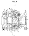
- FIG. 4 is an axial sectional view showing an embodiment of the present invention.
- a cam 1 is provided with a cam face 2 having two or more raised portions formed on its internal side, the cam 1 being coupled to an output shaft not shown for rotations in conjugation with the output shaft.
- the cam 1 is fixedly secured at a weld 3 to a cam housing 4 so as to rotate together with the cam housing 4.
- a rotor 5 is rotatably housed in the cam housing 4 and is coupled to an input shaft 6 for rotations in conjunction with the input shaft 6.
- the rotor 5 is provided axially with a plurality of plunger chambers 7 which accommodate a plurality of plungers 8 slidably by way of return springs 9.
- the rotor 5 is further provided with a plurality of intake/discharge holes 10 which lead to the plunger chambers 7.
- a rotary valve 11 has, on its front face, intake ports 12, intake passages 13 and discharge ports 14.
- the rotary valve 11 has, on its rear face, communication grooves 15 which open to the discharge ports 14.
- the rear face of the rotary valve 11 is provided with a cover member 16 in an intimate contact manner for shutting off the communication grooves 15.
- the rotary valve 11 has also a positioning protrusion 18 to be engaged with a notch 17 formed in the inner periphery of the cam housing 4.
- the rotary valve 11 serves as a timing member for determining the timing to open or close the intake/discharge holes 10, with the notch 17 and the protrusion 18 making up a positioning mechanism for defining the phase relationship between the cam 1 and the rotary valve 11.
- a bearing retainer 19 rotates jointly with the cam housing 4 and provides a support to the input shaft 6 by way of a bearing 20.
- a thrust needle bearing 21 intervenes between the bearing retainer 19 and the rotary valve 11.
- the friction torque associated with the thrust needle bearing 21 is set to be smaller than the friction torque between the rotor 5 and the rotary valve 11.
- An oil seal 22 is interposed between the bearing retainer 19 and the input shaft 6, with the input shaft 6 accommodating slidably therein an accumulator piston 23 for absorbing any thermal expansion and shrinkage of oil.
- the cover member 24 serves to prevent muddy water from entering an O-ring sliding portion in an accumulator chamber 25.
- the accumulator chamber 25 communicates with the interior of the joint by way of oil passages 26 and 27.
- the rotary valve 11 is provided with a high pressure chamber 28 which leads to the discharge ports 14 and of which exit is blocked by a plug 29. Further provided are an oiling hole 30, a needle bearing 31, a threaded hole 32, O-rings 33, 34, snap rings 35, 36 and a mounting hole 37.
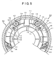
- FIG. 5 is a partially sectional view of the rotary valve 11 taken along a line V-V of FIG. 4.
- the rotary valve 11 within the cam housing 4 of the hydraulic power transmission joint comprises a first torque characteristic shifting mechanism 60 and a second torque characteristic shifting mechanism 62.
- the first torque characteristic shifting mechanism 60 includes an accommodation hole 39, a weight member 41, a drain hole 49, a ball 53 and a spring 47.
- the second torque characteristic shifting mechanism 62 includes an accommodation hole 38, a weight member 40, a drain hole 48, a ball 52 and a spring 46.
- the first torque characteristic shifting mechanism 60 serves to set a torque characteristic switching vehicle velocity V1 (a vehicle velocity at which a first rotational-speed difference is acquired) by means of the spring 47 urging the end of the first weight member 41.
- the second torque characteristic shifting mechanism 62 serves to set a vehicle velocity V2 (a vehicle velocity at which a second rotational-speed difference is acquired) higher than the torque characteristic switching vehicle velocity V1 by means of the spring 46 urging the end of the
- the rotary valve 11 is rotatably housed in the cam housing 4 of the hydraulic power transmission joint.
- the notch 17 is formed in the inner periphery of the cam housing 4 for engagement with the protrusion 18 formed on the outer periphery of the rotary valve 11.
- the discharge ports 14 and the intake ports 12 are alternately formed in the rotary valve 11, the intake ports 12 being in communication with the intake passages 13 which extend up to the outer peripheral face of the rotary valve 11.
- the two accommodation holes 38 and 39 are formed at the outer periphery of the rotary valve 11 outside the discharge ports 14 and the intake ports 12.
- the accommodation holes 38 and 39 are provided in the shape of circumferentially elongated holes.
- the weight members 40 and 41 are accommodated in the accommodation holes 38 and 39, respectively, in such a manner as to be radially (centrifugally) rockable around centers of rotation 42 and 43.
- the weight members 40 and 41 have curved bottoms corresponding to those of the accommodation holes 38 and 39, respectively.
- the weight members 40 and 41 have curved tops and are formed with spring accommodation holes 44 and 45, respectively, at the opposite ends to the centers of rotations 42 and 43.
- the drain holes 48 and 49 are interposed between the accommodation holes 38, 39 and the discharge ports 14 such that the discharge ports 14 can communicate with the accommodation holes 38 and 39 by way of the drain holes 48 and 49, respectively.
- the weight members 40 and 41 Confronting the exits of the drain holes 48 and 49, the weight members 40 and 41 have accommodation grooves 50 and 51, respectively, formed in their bottoms.
- the accommodation grooves 50 and 51 accommodate the balls 52 and 53, respectively, which normally block the drain holes 48 and 49, respectively.
- Predetermined gaps 54 and 55 are formed between the weight members 40 and 41 and the accommodation holes 38 and 39, respectively.
- the torque characteristic shifting mechanisms are constituted of the accommodation holes 38 and 39, the weight members 40 and 41, the drain holes 48 and 49, the balls 52 and 53, and the springs 4 6 and 47, respectively.
- the springs 46 and 47 bias the respective ends of the weight members 40 and 41, respectively, by predetermined spring forces.
- the drain holes 48 and 49 are blocked by the balls 52 and 53 accommodated in the accommodation grooves 50 and 51 formed in the bottoms of the weight members 40 and 41, the area of contact of the ball 52 on one hand with the drain hole 48 is formed so as to be larger than the area of contact of the ball 53 on the other with the drain hole 49. Therefore, when a predetermined vehicle velocity V1 is reached and the weight member 41 rocks in the centrifugal direction by the centrifugal force, the ball 53 opens the drain hole 49. When the vehicle velocity further reaches a certain predetermined value V2 higher than the predetermined vehicle velocity and the weight member 40 rocks in the centrifugal direction, the ball 52 opens the drain 48. The torque is thus varied in a stepwise manner.
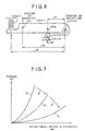
- FIG. 6 shows the second torque characteristic shifting mechanism 62 in an exclusive manner, with the reference numerals parenthesized for the first torque characteristic shifting mechanism 60.
- FIG. 7 illustrates the balance of points at which the torque characteristics are changed over in the torque characteristic shifting mechanism of FIG. 6.
- the weight member 40 (41) rocks in the centrifugal direction around the center of rotation 42 (43). With the ball 52 (53) blocking the drain hole 48 (49), let A and ⁇ P be the area of contact of the ball 52 (53) with the drain hole 48 (49) and the discharge pressure, then ⁇ • A acts on the weight member 40 (41) as a thrust-up force lifting the weight member 40 (41).
- the spring 46 (47) presses the end of the weight member 40 (41) by a spring force P.
- the spring force P of the spring 46 (47) can be R1/R3, thus enabling the space for accommodating the springs 46 (47) to be reduced to a great extent.
- a further rotation of the cam 1 causes the intake strokes, allowing the intake/discharge holes 10 to communicate with the intake ports 12, with the result that the oil in the intake passages 13 is taken through the intake ports 12 and the intake/discharge holes 10 into the plunger chambers 7 so that the plungers 8 are returned along the cam face 2 of the cam 1.
- the centrifugal force will not reach a predetermined value either, with the result that any torque reduction will not occur. That is, if the vehicle velocity V does not reach the certain value V1, then the centrifugal forces acting on the weight members 40 and 41 will be smaller than the spring forces of the springs 46 and 47, so that the weight members 40 and 41 will not rock. For this reason, the drain holes 48 and 49 remain blocked by the balls 52 and 53. Thus, the torque characteristic at this time results in a normal torque characteristic in the form of a curve D of FIG. 7.
- R3 ⁇ R2 > R1 or R2 > R3 > R1 where R1, R2 and R3 are the distance from the center of rotation 42, 43 to the center of the ball 52, 53, the distance from the center of rotation 42, 43 to the center of gravity 5 6 of the weight member 40, 41 and the distance from the center of rotation 42, 43 to the center of the spring 46, 47, respectively, the same performances as the prior art can be obtained by the spring force equal to R1/R3 when the vehicle velocity V is zero.
- the spring accommodation space can thus be reduced to a great extent, achieving a reduction in size of the joint.
- the distances are set so as to meet the relationships R3 ⁇ R2 > R1 or R2 > R3 > R1 where R1, R2 and R3 are the distance from the center of rotation of the weight member to the center of the ball blocking the drain hole, the distance from the center of rotation to the center of gravity of the weight member and the distance from the center of rotation to the center of the spring, respectively, R1/R3 will suffice for the spring force when the vehicle velocity is zero in order to obtain the same performances as the prior art, whereupon the spring accommodation space can be reduced to a great extent, achieving a reduction in size of the joint.
- R1/R2 will suffice for the mass of the weight member R2 when the thrust-up force lifting the ball is constant, so that the external diameter and the overall length can be reduced to a great extent, achieving a reduction in size of the joint.
- the provision of a plurality of torque characteristic shifting mechanisms allows the torque characteristics to vary in a stepwise manner, thus preventing any variances in vehicle behaviors arising from torque variations.
Landscapes
- Engineering & Computer Science (AREA)
- General Engineering & Computer Science (AREA)
- Mechanical Engineering (AREA)
- Chemical & Material Sciences (AREA)
- Combustion & Propulsion (AREA)
- Transportation (AREA)
- Physics & Mathematics (AREA)
- Fluid Mechanics (AREA)
- Arrangement And Driving Of Transmission Devices (AREA)
- Hydraulic Clutches, Magnetic Clutches, Fluid Clutches, And Fluid Joints (AREA)
- Transmissions By Endless Flexible Members (AREA)
Description
Claims (6)
- A hydraulic power transmission joint for transmitting torque in response to a rotational-speed difference between input and output shafts capable of relative rotations, said joint comprising:a cam housing (4) interposed between said input and output shafts and coupled to one of said shafts, said cam housing (4) being provided with a cam face (2) having two or more raised portions formed on its internal side;a rotor (5) coupled to the other of said shafts and rotatably housed in said cam housing (4), said rotor (5) having a plurality of axially extending plunger chambers (7);a plurality of plungers (8) each reciprocatively accommodated in each of said plurality of plunger chambers (7) under a pressing force of a return spring (9), said plurality of plungers (8) being operated by said cam face (2) upon said relative rotations of said two shafts;an intake/discharge hole (10) formed in said rotor (5) and leading to said plurality of plunger chambers (7);a rotary valve (11) being in rotatable sliding contact with an end face of said rotor (5), said rotary valve (11) being positioned relative to said rotor (5) in a predetermined relationship, said rotary valve (11) having on its surface a plurality of intake ports (12) and a plurality of discharge ports (14) acting respectively as intake valves and discharge valves depending on a positional relationship relative to said intake/discharge hole (10);an orifice generating a flow resistance as a result of flow of oil discharged by the operation of said plungers (8); anda torque characteristic shifting mechanism (60, 62) for changing over torque transmission characteristics in a stepwise manner depending on a rotational-speed difference between said two shafts;said torque characteristic shifting mechanism (60, 62) including:an accommodation hole (38, 39) formed outside of said discharge ports (14) of said rotary valve (11);a weight member (40, 41) received in said accommodation hole (38, 39) rockably around a center of rotation by the action of a centrifugal force;a drain hole (48, 49) for allowing a communication between said accommodation hole (38, 39) and said discharge ports (14);a ball (52, 53) located under said weight member (40, 41) for blocking said drain hole (48,49), said ball (52, 53) serving to open said drain hole (48, 49) when said weight member (40, 41) rocks by a centrifugal force; anda spring (46, 47) for urging the end portion of said weight member (40, 41) opposite to said center of rotation, said spring (46, 47) setting a predetermined rotational-speed difference as a torque characteristic changeover point.
- A hydraulic power transmission joint according to claim 1, wherein said torque characteristic shifting mechanism (60, 62) sets the distances so as to meet a relationship R3 ≒ R2 > R1 where R1, R2 and R3 are the distance from said center of rotation to a center of said ball (52, 53), the distance from said center of rotation to a center of gravity of said weight member (40, 41) and the distance from said center of rotation to a center of said spring (46, 47), respectively.
- A hydraulic power transmission joint according to claim 1, wherein said torque characteristic shifting mechanism (60, 62) sets the distances so as to meet a relationship R2 > R3 > R1 where R1, R2 and R3 are the distance from said center of rotation to a center of said ball (52, 53), the distance from said center of rotation to a center of gravity of said weight members (40, 41) and the distance from said center of rotation to a center of said spring (46, 47), respectively.
- A hydraulic power transmission joint according to claim 1, wherein it comprises a plurality of torque characteristic shifting mechanisms (60, 62) each consisting of said accommodation hole (38, 39), said weight member (40, 41), said drain hole (48, 49), said ball (52, 53) and said spring (46, 47), so as to change over torque transmission characteristics at three or more steps in response to a rotational-speed difference between said two shafts.
- A hydraulic power transmission joint according to claim 4, wherein
it comprises:a first torque characteristic shifting mechanism (60) consisting of a first accommodation hole (39), a first weight member (41), a first drain hole (49), a first ball (53) and a first spring (47); anda second torque characteristic shifting mechanism (62) consisting of a second accommodation hole (38), a second weight member (40), a second drain hole (48), a second ball (52) and a second spring (46), and whereinsaid first torque characteristic shifting mechanism (60) sets a first rotational-speed difference at which the torque characteristic is changed over by the action of said first spring (47) pressing the end portion of said first weight member (41), and whereinsaid second torque characteristic shifting mechanism (62) sets a second rotational-speed difference higher than said first rotational-speed difference, at which the torque characteristic is changed over by the action of said second spring (46) pressing the end portion of said second weight member (40). - A hydraulic power transmission joint according to claim 1, wherein said input and output shafts are front and rear shafts of a motor vehicle equipped with tires having different diameters, and wherein said joint generates torque as a function of a rotational-speed difference between said shafts, said rotational-speed difference increasing accordingly as the vehicle velocity increases.
Applications Claiming Priority (2)
| Application Number | Priority Date | Filing Date | Title |
|---|---|---|---|
| JP11642099A JP3326134B2 (en) | 1999-04-23 | 1999-04-23 | Hydraulic power transmission coupling |
| JP11642099 | 1999-04-23 |
Publications (2)
| Publication Number | Publication Date |
|---|---|
| EP1046830A1 EP1046830A1 (en) | 2000-10-25 |
| EP1046830B1 true EP1046830B1 (en) | 2004-03-24 |
Family
ID=14686651
Family Applications (1)
| Application Number | Title | Priority Date | Filing Date |
|---|---|---|---|
| EP00107878A Expired - Lifetime EP1046830B1 (en) | 1999-04-23 | 2000-04-12 | Hydraulic power transmission joint |
Country Status (4)
| Country | Link |
|---|---|
| US (1) | US6283264B1 (en) |
| EP (1) | EP1046830B1 (en) |
| JP (1) | JP3326134B2 (en) |
| DE (1) | DE60009192T2 (en) |
Family Cites Families (9)
| Publication number | Priority date | Publication date | Assignee | Title |
|---|---|---|---|---|
| US3913715A (en) * | 1974-08-22 | 1975-10-21 | Twin Disc Inc | Modulatable friction clutch controlled by a centrifugal force and angular acceleration sensitive valve |
| US5037353A (en) * | 1989-01-17 | 1991-08-06 | Fuji Tekko Co., Ltd. | Hydraulic power transmission joint which is used in vehicles |
| US5103642A (en) * | 1990-07-12 | 1992-04-14 | Fuji Tekko Co., Ltd. | Rotary shaft coupler with rotary valve plate position dependent on direction of shaft rotation |
| US5297994A (en) * | 1991-12-20 | 1994-03-29 | Fuji Univance Corporation | Hydraulic power transmission joint which is used in vehicles |
| US5536215A (en) * | 1993-02-10 | 1996-07-16 | Asha Corporation | Hydraulic coupling for vehicle drivetrain |
| JP3069257B2 (en) * | 1995-01-17 | 2000-07-24 | 株式会社フジユニバンス | Hydraulic power transmission coupling |
| US5706658A (en) | 1995-01-17 | 1998-01-13 | Fuji Univance Corporation | Rotary shaft coupler with rotary valve plate position dependent on direction of shaft rotation |
| JP2886816B2 (en) * | 1995-12-05 | 1999-04-26 | 株式会社フジユニバンス | Hydraulic power transmission coupling |
| JP3401392B2 (en) * | 1996-10-04 | 2003-04-28 | 株式会社フジユニバンス | Hydraulic power transmission coupling |
-
1999
- 1999-04-23 JP JP11642099A patent/JP3326134B2/en not_active Expired - Lifetime
-
2000
- 2000-04-12 EP EP00107878A patent/EP1046830B1/en not_active Expired - Lifetime
- 2000-04-12 DE DE60009192T patent/DE60009192T2/en not_active Expired - Lifetime
- 2000-04-20 US US09/553,016 patent/US6283264B1/en not_active Expired - Lifetime
Also Published As
| Publication number | Publication date |
|---|---|
| EP1046830A1 (en) | 2000-10-25 |
| DE60009192T2 (en) | 2004-09-16 |
| JP3326134B2 (en) | 2002-09-17 |
| JP2000310245A (en) | 2000-11-07 |
| US6283264B1 (en) | 2001-09-04 |
| DE60009192D1 (en) | 2004-04-29 |
Similar Documents
| Publication | Publication Date | Title |
|---|---|---|
| JPS61153057A (en) | Hydrostatic continuously variable transmission | |
| US6530218B2 (en) | Hydrostatic continuously variable transmission | |
| US5375687A (en) | Torque transmission device of a four-wheel drive vehicle | |
| EP1167843B1 (en) | Shuttle valve with improved shifting | |
| EP0768478B1 (en) | Automatic clutch device for hydrostatic continuously variable transmission | |
| EP0648959B1 (en) | Hydraulic continuously-variable-transmission | |
| EP0309223B1 (en) | Hydrostatic continuously variable transmission | |
| EP1046830B1 (en) | Hydraulic power transmission joint | |
| US5038634A (en) | Power transmission system | |
| US5394698A (en) | Hydraulic transmission apparatus | |
| EP0768479B1 (en) | Hydrostatic continuously variable transmission | |
| EP0273631B1 (en) | Hydraulically operated continuously variable transmission | |
| JP3069257B2 (en) | Hydraulic power transmission coupling | |
| JP3401392B2 (en) | Hydraulic power transmission coupling | |
| JPH08284977A (en) | Hydraulic power transmission | |
| JP2886795B2 (en) | Hydraulic power transmission coupling | |
| US6341682B1 (en) | Hydraulic power transmission joint | |
| JP2905802B2 (en) | Hydraulic power transmission coupling | |
| JPH0781634B2 (en) | Hydrostatic continuously variable transmission | |
| JP3486509B2 (en) | Hydraulic power transmission coupling | |
| JP2931705B2 (en) | Hydraulic power transmission coupling | |
| JPH09196140A (en) | Continuously variable transmission | |
| JPH0617925A (en) | Hydrostatic continuously variable transmission | |
| JPH06241247A (en) | Speed differential sensitive coupling | |
| JPH0742992B2 (en) | Hydraulic power transmission coupling |
Legal Events
| Date | Code | Title | Description |
|---|---|---|---|
| PUAI | Public reference made under article 153(3) epc to a published international application that has entered the european phase |
Free format text: ORIGINAL CODE: 0009012 |
|
| AK | Designated contracting states |
Kind code of ref document: A1 Designated state(s): AT BE CH CY DE DK ES FI FR GB GR IE IT LI LU MC NL PT SE |
|
| AX | Request for extension of the european patent |
Free format text: AL;LT;LV;MK;RO;SI |
|
| 17P | Request for examination filed |
Effective date: 20001027 |
|
| AKX | Designation fees paid |
Free format text: DE FR GB |
|
| GRAP | Despatch of communication of intention to grant a patent |
Free format text: ORIGINAL CODE: EPIDOSNIGR1 |
|
| GRAS | Grant fee paid |
Free format text: ORIGINAL CODE: EPIDOSNIGR3 |
|
| GRAA | (expected) grant |
Free format text: ORIGINAL CODE: 0009210 |
|
| AK | Designated contracting states |
Kind code of ref document: B1 Designated state(s): DE FR GB |
|
| REG | Reference to a national code |
Ref country code: GB Ref legal event code: FG4D |
|
| REF | Corresponds to: |
Ref document number: 60009192 Country of ref document: DE Date of ref document: 20040429 Kind code of ref document: P |
|
| ET | Fr: translation filed | ||
| PLBE | No opposition filed within time limit |
Free format text: ORIGINAL CODE: 0009261 |
|
| STAA | Information on the status of an ep patent application or granted ep patent |
Free format text: STATUS: NO OPPOSITION FILED WITHIN TIME LIMIT |
|
| 26N | No opposition filed |
Effective date: 20041228 |
|
| REG | Reference to a national code |
Ref country code: FR Ref legal event code: PLFP Year of fee payment: 16 |
|
| REG | Reference to a national code |
Ref country code: FR Ref legal event code: PLFP Year of fee payment: 17 |
|
| REG | Reference to a national code |
Ref country code: FR Ref legal event code: PLFP Year of fee payment: 18 |
|
| REG | Reference to a national code |
Ref country code: FR Ref legal event code: PLFP Year of fee payment: 19 |
|
| PGFP | Annual fee paid to national office [announced via postgrant information from national office to epo] |
Ref country code: DE Payment date: 20190426 Year of fee payment: 20 |
|
| PGFP | Annual fee paid to national office [announced via postgrant information from national office to epo] |
Ref country code: FR Payment date: 20190423 Year of fee payment: 20 |
|
| PGFP | Annual fee paid to national office [announced via postgrant information from national office to epo] |
Ref country code: GB Payment date: 20190424 Year of fee payment: 20 |
|
| REG | Reference to a national code |
Ref country code: DE Ref legal event code: R071 Ref document number: 60009192 Country of ref document: DE |
|
| REG | Reference to a national code |
Ref country code: GB Ref legal event code: PE20 Expiry date: 20200411 |
|
| PG25 | Lapsed in a contracting state [announced via postgrant information from national office to epo] |
Ref country code: GB Free format text: LAPSE BECAUSE OF EXPIRATION OF PROTECTION Effective date: 20200411 |