EP1046829A2 - Clutch disc assembly with reinforcing plate welded thereto - Google Patents
Clutch disc assembly with reinforcing plate welded thereto Download PDFInfo
- Publication number
- EP1046829A2 EP1046829A2 EP00108497A EP00108497A EP1046829A2 EP 1046829 A2 EP1046829 A2 EP 1046829A2 EP 00108497 A EP00108497 A EP 00108497A EP 00108497 A EP00108497 A EP 00108497A EP 1046829 A2 EP1046829 A2 EP 1046829A2
- Authority
- EP
- European Patent Office
- Prior art keywords
- reinforcing plate
- disc assembly
- annular
- spring
- plate
- Prior art date
- Legal status (The legal status is an assumption and is not a legal conclusion. Google has not performed a legal analysis and makes no representation as to the accuracy of the status listed.)
- Granted
Links
- 230000003014 reinforcing effect Effects 0.000 title claims abstract description 41
- 239000011324 bead Substances 0.000 claims abstract description 7
- 238000000034 method Methods 0.000 claims description 4
- 238000003466 welding Methods 0.000 claims description 3
- 230000005540 biological transmission Effects 0.000 description 7
- 239000002783 friction material Substances 0.000 description 5
- 239000002184 metal Substances 0.000 description 3
- 229910000831 Steel Inorganic materials 0.000 description 2
- 238000013016 damping Methods 0.000 description 2
- 238000004806 packaging method and process Methods 0.000 description 2
- 239000010959 steel Substances 0.000 description 2
- 238000005266 casting Methods 0.000 description 1
- 238000002485 combustion reaction Methods 0.000 description 1
- 238000005242 forging Methods 0.000 description 1
- 239000000463 material Substances 0.000 description 1
- 238000012986 modification Methods 0.000 description 1
- 230000004048 modification Effects 0.000 description 1
- 238000006467 substitution reaction Methods 0.000 description 1
Images

Classifications
-
- F—MECHANICAL ENGINEERING; LIGHTING; HEATING; WEAPONS; BLASTING
- F16—ENGINEERING ELEMENTS AND UNITS; GENERAL MEASURES FOR PRODUCING AND MAINTAINING EFFECTIVE FUNCTIONING OF MACHINES OR INSTALLATIONS; THERMAL INSULATION IN GENERAL
- F16D—COUPLINGS FOR TRANSMITTING ROTATION; CLUTCHES; BRAKES
- F16D13/00—Friction clutches
- F16D13/58—Details
- F16D13/60—Clutching elements
- F16D13/64—Clutch-plates; Clutch-lamellae
-
- F—MECHANICAL ENGINEERING; LIGHTING; HEATING; WEAPONS; BLASTING
- F16—ENGINEERING ELEMENTS AND UNITS; GENERAL MEASURES FOR PRODUCING AND MAINTAINING EFFECTIVE FUNCTIONING OF MACHINES OR INSTALLATIONS; THERMAL INSULATION IN GENERAL
- F16F—SPRINGS; SHOCK-ABSORBERS; MEANS FOR DAMPING VIBRATION
- F16F15/00—Suppression of vibrations in systems; Means or arrangements for avoiding or reducing out-of-balance forces, e.g. due to motion
- F16F15/10—Suppression of vibrations in rotating systems by making use of members moving with the system
- F16F15/12—Suppression of vibrations in rotating systems by making use of members moving with the system using elastic members or friction-damping members, e.g. between a rotating shaft and a gyratory mass mounted thereon
- F16F15/121—Suppression of vibrations in rotating systems by making use of members moving with the system using elastic members or friction-damping members, e.g. between a rotating shaft and a gyratory mass mounted thereon using springs as elastic members, e.g. metallic springs
- F16F15/123—Wound springs
Definitions
- This invention relates in general to friction clutches and in particular to the structure of clutch driven discs.
- Clutches are well known devices used to selectively connect a source of rotational power, such as the crankshaft of an internal combustion engine and its flywheel, to a driven mechanism, such as a transmission.
- clutches have a driven disc rotatably fixed to the transmission input shaft and axially disposed between a flywheel and a pressure plate. Both the flywheel and the pressure plate are rotatably fixed to the output shaft of the engine.
- the pressure plate is axially biased toward the flywheel by an axial spring load. When the clutch is in an engaged condition, the pressure plate clamps the driven disc against the flywheel. Friction material is disposed on the driven disc to resist slipping between the driven disc and both the pressure plate and the flywheel.
- the driven disc is annularly divided into two relatively rotatable portions: the hub which is rotatively fixed to the input shaft, and the annular disc assembly which bears the friction material.
- the damping springs are disposed between the hub and the annular disc assembly.
- the annular disc assembly has a relatively stiff portion, called a reinforcing plate, which engages the damper springs.
- a thinner annular disc extends outwardly radially from the reinforcing plate and bears the friction material. Using thinner material for the annular disc than the reinforcing plate allows the assembly to be of sufficient strength to engage the damper springs while being of relatively low rotative inertia.
- the annular disc is riveted to the reinforcing plate. It is desired to provide a connection between the annular disc and the reinforcing plate which is stronger than the connection provided by rivets. It is also desired to provide a connection between the reinforcing plate and the annular disc which is well suited for adapting to specific packaging and space constraint limitations within a clutch assembly.
- a clutch driven disc assembly includes a hub, an annular spring plate, an annular disc assembly, and a plurality of drive springs.
- the hub has an axis of rotation.
- the annular spring plate rotatably is fixed to the hub.
- the annular disc assembly is mounted concentric with the axis of rotation for rotation relative to the spring plate.
- the plurality of drive springs is operably disposed between the spring plate and the disc assembly.
- the disc assembly has a reinforcing plate with spring pockets which receive the drive springs.
- the reinforcing plate has oppositely facing faces.
- the annular disc assembly also has an annular disc with a friction element fixed thereto and also has a plurality of attachment apertures passing therethrough. The weld bead is disposed in each of the attachment apertures and fixes the annular disc to one of the reinforcing plate faces.
- This invention provides a clutch driven disc which has a connection between its annular disc and reinforcing plate which is stronger than a connection provided by rivets. This invention also provides a connection between the reinforcing plate and the annular disc which is well suited for adapting to specific packaging and space constraint limitations within a clutch assembly.
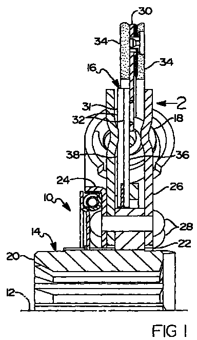
- a clutch driven disc assembly 10 as shown in Fig. 1 includes an axis of rotation 12, a hub assembly 14, a disc assembly 16 and a plurality of damping or drive springs 18 disposed between hub assembly 14 and disc assembly 16.
- Hub assembly 14 includes an inner hub 20 and an outer hub 22.
- a predamper 24 is disposed between inner hub 20 and outer hub 22.
- a pair of spring plates 26 are fixed to outer hub 22 by rivets 28.
- Disc assembly 16 includes an annular disc 30 attached to an annular reinforcing plate 31 defined by a pair of overlapped stack plates 32.
- Stack plates 32 are axially disposed between spring plates 26.
- Drive springs 18 are disposed simultaneously in spring pockets 33 in stack plates 32 and spring pockets in spring plates 26. Relative rotation of disc assembly 16 to hub assembly 14 compresses drive springs 18.
- Stack plates 32 can be fixed to each other by rivets (not shown), welding or any other appropriate means.
- Reinforcing plate 31 can alternatively be formed as a single, thicker plate in place of the thinner stack plates 32.
- Annular disc 30 has friction element 34 made of friction material on both sides thereof for frictional engagement with a clutch flywheel (not shown) and a clutch pressure plate (not shown) when installed in a vehicle.
- annular disc 30 is attached to reinforcing plate 31 on an engine face 36 of plate 31.
- the engine face is the side which is directed toward the engine and the flywheel when disc assembly 10 is installed in a vehicle.
- friction elements 34 can advantageously be positioned in a preferred location relative to spring plates 26 and hub assembly 14 with little or no axial offset of flanges 40 relative to the portion of disc 30 carrying friction elements 34. Such positioning may be necessitated by space limitations within the clutch and within clutch driven disc assembly 10.
- disc 30 may be attached to a transmission face 38 of plate 31 if space considerations so demand.
- Disc 30 is fixed to either face 36 or 38 by welding.
- Disc 30 has radially inwardly extending flanges 40 which overlap plate 31 and are interposed between spring pockets 33.
- Flanges 40 each have an elongated weld aperture 42 also overlapping plate 31.
- a weld bead 44 circumscribes each aperture 42, fixing disc 30 to plate 31.
- the elongate shape advantageously increases the amount of weld metal of the connection given a relatively small amount of radial overlap between flanges 40 and plate 31.
- clutch driven discs fall into a category of devices which can be described as torsional dampers.
- Another type of torsional damper which is known simply as a torsional damper is employed with automatic transmissions. Such torsional dampers are disposed between between an engine crankshaft and an automatic transmission torque converter.
- the torsional damper has essentially the same structure as the above described driven disc assembly 10, but without friction elements 34.
- annular disc 30 would be bolted to the torque converter and hub assembly 14 would be bolted to the engine crankshaft.
- Such torsional dampers would benefit from the above described reinforcing plate 31 to annular disc 30 attachment in the same manner that the driven disc assembly benefits.
- Hub 14 is formed by conventional means, including stamping, forging, casting or other appropriate metal forming processes.
- Annular spring plates 26 are similarly formed by an appropriate metal forming process and rotatably fixed to hub 14.
- Annular disc assembly 16 is located concentric with spring plates 26 for rotation relative to spring plate 26.
- a plurality of drive springs 18 are installed between spring plates 26 and disc assembly 16.
- Annular disc assembly 16 is first assembled from reinforcing plate 31 and annular disc 30.
- Reinforcing plate 31 is stamped of steel and has spring pockets 33 formed therein configured to receive springs 18.
- Annular disc 30 is stamped of steel and has a plurality of radially inwardly extending flanges 40.
- Attachment apertures 42 are formed in each of flanges 40.
- Flanges 40 are configured to overlap reinforcing plate 31.
- Flanges 40 are placed over engine face 36 between spring pockets 33 of reinforcing plate 31.
- Annular disc 30 is welded to reinforcing plate 31 by placing a weld bead 44 around each of attachment apertures 42, thereby fixing annular disc 30 to reinforcing plate face 36.
Landscapes
- Engineering & Computer Science (AREA)
- General Engineering & Computer Science (AREA)
- Mechanical Engineering (AREA)
- Physics & Mathematics (AREA)
- Acoustics & Sound (AREA)
- Aviation & Aerospace Engineering (AREA)
- Mechanical Operated Clutches (AREA)
Abstract
Description
Claims (9)
- A clutch driven disc assembly comprising:a hub having an axis of rotation;an annular spring plate rotatably fixed to the hub;an annular disc assembly mounted concentric with the axis of rotation for rotation relative to the spring plate;a plurality of drive springs operably disposed between the spring plate and the disc assembly;the disc assembly including:a reinforcing plate having spring pockets receiving the drive springs and the reinforcing plate also having oppositely facing faces;an annular disc having a friction element fixed thereto and having a plurality of attachment apertures; anda weld bead disposed in each of the attachment apertures fixing the annular disc to one of the reinforcing plate faces.
- A clutch driven disc assembly as claimed in claim 1 wherein the annular disc has a plurality of radially inwardly extending flanges overlapping the reinforcing plate in which are defined the attachment apertures.
- A clutch driven disc assembly as claimed in claim 2 wherein the flanges extend between the spring pockets of the reinforcing plate.
- A clutch driven disc assembly as claimed in claim 1 wherein the apertures are elongated in the circumferential direction.
- A torsional damper comprising:a hub having an axis of rotation;an annular spring plate rotatably fixed to the hub;an annular disc assembly mounted concentric with the axis of rotation for rotation relative to the spring plate;a plurality of drive springs operably disposed between the spring plate and the disc assembly;the disc assembly including:a reinforcing plate having spring pockets receiving the drive springs and the reinforcing plate also having oppositely facing faces;an annular disc having a plurality of attachment apertures; anda weld bead disposed in each of the attachment apertures fixing the annular disc to one of the reinforcing plate faces.
- A torsional damper as claimed in claim 5 wherein the annular disc has a plurality of radially inwardly extending flanges overlapping the reinforcing plate in which are defined the attachment apertures.
- A torsional damper as claimed in claim 6 wherein the flanges extend between the spring pockets of the reinforcing plate.
- A torsional damper as claimed in claim 5 wherein the apertures are elongated in the circumferential direction.
- A method for fabricating a torsional damper including the steps of:forming a hub;rotatably fixing an annular spring plate to the hub concentric thereto;mounting an annular disc assembly concentric with the hub for rotation relative to the spring plate;installing a plurality of drive springs between the spring plate and the disc assembly;forming the the disc assembly by:forming a reinforcing plate to have oppositely facing face and having spring pockets configured to receive the drive springs;forming an annular disc having a plurality of radially inwardly extending flanges configured to overlap the reinforcing plate in which are defined attachment apertures;placing the flanges over one of the reinforcing plate faces and between the spring pockets of the reinforcing plate; andwelding the annular disc to the reinforcing plate by placing a weld bead around each of the attachment apertures, thereby fixing the annular disc to one of the reinforcing plate faces.
Applications Claiming Priority (2)
| Application Number | Priority Date | Filing Date | Title |
|---|---|---|---|
| US299594 | 1999-04-23 | ||
| US09/299,594 US6105744A (en) | 1999-04-23 | 1999-04-23 | Welded annular disc and reinforcing plate assembly |
Publications (3)
| Publication Number | Publication Date |
|---|---|
| EP1046829A2 true EP1046829A2 (en) | 2000-10-25 |
| EP1046829A3 EP1046829A3 (en) | 2002-01-16 |
| EP1046829B1 EP1046829B1 (en) | 2006-08-30 |
Family
ID=23155463
Family Applications (1)
| Application Number | Title | Priority Date | Filing Date |
|---|---|---|---|
| EP00108497A Expired - Lifetime EP1046829B1 (en) | 1999-04-23 | 2000-04-19 | Clutch disc assembly with reinforcing plate welded thereto |
Country Status (3)
| Country | Link |
|---|---|
| US (1) | US6105744A (en) |
| EP (1) | EP1046829B1 (en) |
| DE (1) | DE60030351T2 (en) |
Cited By (1)
| Publication number | Priority date | Publication date | Assignee | Title |
|---|---|---|---|---|
| WO2008049387A3 (en) * | 2006-10-26 | 2008-06-19 | Luk Lamellen & Kupplungsbau | Clutch plate |
Families Citing this family (3)
| Publication number | Priority date | Publication date | Assignee | Title |
|---|---|---|---|---|
| US20040118645A1 (en) * | 2001-03-27 | 2004-06-24 | Eaton Corporation | Clutch driven disc friction material mounting |
| US6923305B2 (en) * | 2003-08-12 | 2005-08-02 | Eaton Corporation | Clutch driven disk with predamper |
| DE102008008413A1 (en) | 2008-02-09 | 2009-08-13 | Zf Friedrichshafen Ag | Clutch disk for motor vehicle friction clutch, comprises interior hub with internal gear and external gear, and interior hub encloses external hub with internal teeth intervening in external teeth which act in torque proof manner |
Family Cites Families (7)
| Publication number | Priority date | Publication date | Assignee | Title |
|---|---|---|---|---|
| US1782234A (en) * | 1928-12-31 | 1930-11-18 | Otto U Hofmann | Method of welding and the resultant product |
| FR1572343A (en) * | 1968-04-09 | 1969-06-27 | ||
| GB2044864B (en) * | 1979-03-09 | 1983-09-28 | Ferodo Ltd | Friction clutch driven plates |
| DE3436583C2 (en) * | 1984-10-05 | 1994-09-15 | Fichtel & Sachs Ag | Clutch disc for friction clutch |
| DE3908348C2 (en) * | 1989-03-15 | 1997-07-31 | Fichtel & Sachs Ag | Clutch disc with friction device inside the friction linings |
| FR2690960B1 (en) * | 1992-05-07 | 1998-03-20 | Valeo | FRICTION DISC FOR CLUTCH, PARTICULARLY FOR MOTOR VEHICLE. |
| DE59301210D1 (en) * | 1992-10-22 | 1996-02-01 | Fichtel & Sachs Ag | Driving plate for a clutch plate of a motor vehicle friction clutch and method for its production |
-
1999
- 1999-04-23 US US09/299,594 patent/US6105744A/en not_active Expired - Fee Related
-
2000
- 2000-04-19 EP EP00108497A patent/EP1046829B1/en not_active Expired - Lifetime
- 2000-04-19 DE DE60030351T patent/DE60030351T2/en not_active Expired - Fee Related
Cited By (1)
| Publication number | Priority date | Publication date | Assignee | Title |
|---|---|---|---|---|
| WO2008049387A3 (en) * | 2006-10-26 | 2008-06-19 | Luk Lamellen & Kupplungsbau | Clutch plate |
Also Published As
| Publication number | Publication date |
|---|---|
| US6105744A (en) | 2000-08-22 |
| DE60030351D1 (en) | 2006-10-12 |
| EP1046829A3 (en) | 2002-01-16 |
| DE60030351T2 (en) | 2007-08-30 |
| EP1046829B1 (en) | 2006-08-30 |
Similar Documents
| Publication | Publication Date | Title |
|---|---|---|
| JP4277501B2 (en) | Torque fluctuation absorber | |
| US4684007A (en) | Clutch plate | |
| US6450314B2 (en) | Apparatus for damping torsional vibrations | |
| US7581299B2 (en) | Method of assembling a damper unit | |
| JP6976940B2 (en) | Torsional vibration damper for hydrodynamic torque coupling device with inner and outer elastic damping members connected in series | |
| JP6832351B2 (en) | Torsional vibration damper for hydrodynamic torque coupling device | |
| US4785924A (en) | Torque transmitting assembly | |
| US4596324A (en) | Clutch plate | |
| US8739654B2 (en) | Torque transmission device | |
| US6193037B1 (en) | Hydrodynamic torque converter | |
| US6062103A (en) | Motor vehicle double damping flywheel, comprising improved means for friction damping of vibrations | |
| US9255610B2 (en) | Torque transmission device | |
| US5927459A (en) | Modular clutch | |
| US5823311A (en) | Flywheel, in particular for motor vehicles | |
| US6273226B1 (en) | Hydrokinetic torque converter | |
| CN113446354A (en) | Dual mass flywheel | |
| JPH1047453A (en) | Torque converter with lock-up clutch | |
| US8597130B2 (en) | Force transmission flange for a torque transmission device or a damper device, and torque transmission device or damper device | |
| US7166030B2 (en) | Torsional vibration damper | |
| US6105744A (en) | Welded annular disc and reinforcing plate assembly | |
| US6035993A (en) | Friction clutch with pre-damper | |
| US6209696B1 (en) | Friction clutch equipped with flexible flywheel | |
| US20060006040A1 (en) | Pressure plate assembly, clutch disk arrangement, and friction clutch, especially a multi-disk clutch | |
| JPH09310725A (en) | Modular clutch | |
| US20130153357A1 (en) | Series Damper For Single and Twin Friction Plate HD Clutch |
Legal Events
| Date | Code | Title | Description |
|---|---|---|---|
| PUAI | Public reference made under article 153(3) epc to a published international application that has entered the european phase |
Free format text: ORIGINAL CODE: 0009012 |
|
| AK | Designated contracting states |
Kind code of ref document: A2 Designated state(s): DE FR GB IT NL SE Kind code of ref document: A2 Designated state(s): AT BE CH CY DE DK ES FI FR GB GR IE IT LI LU MC NL PT SE |
|
| AX | Request for extension of the european patent |
Free format text: AL;LT;LV;MK;RO;SI |
|
| RIN1 | Information on inventor provided before grant (corrected) |
Inventor name: BASSETT, MICHAEL LEE Inventor name: GOCHENOUR, DAN VERN Inventor name: SCHLOSSER, KEVIN FRANCIS Inventor name: BATTERTON, GREGORY W. Inventor name: SZADKOWSKI, ANDRZEJ PIOTR Inventor name: UTHOFF, LOREN HERBERT, JR. |
|
| PUAL | Search report despatched |
Free format text: ORIGINAL CODE: 0009013 |
|
| RIC1 | Information provided on ipc code assigned before grant |
Free format text: 7F 16D 13/68 A, 7F 16F 15/12 B |
|
| AK | Designated contracting states |
Kind code of ref document: A3 Designated state(s): AT BE CH CY DE DK ES FI FR GB GR IE IT LI LU MC NL PT SE |
|
| AX | Request for extension of the european patent |
Free format text: AL;LT;LV;MK;RO;SI |
|
| 17P | Request for examination filed |
Effective date: 20020322 |
|
| AKX | Designation fees paid |
Free format text: DE FR GB IT NL SE |
|
| GRAP | Despatch of communication of intention to grant a patent |
Free format text: ORIGINAL CODE: EPIDOSNIGR1 |
|
| GRAS | Grant fee paid |
Free format text: ORIGINAL CODE: EPIDOSNIGR3 |
|
| GRAA | (expected) grant |
Free format text: ORIGINAL CODE: 0009210 |
|
| AK | Designated contracting states |
Kind code of ref document: B1 Designated state(s): DE FR GB IT NL SE |
|
| PG25 | Lapsed in a contracting state [announced via postgrant information from national office to epo] |
Ref country code: IT Free format text: LAPSE BECAUSE OF FAILURE TO SUBMIT A TRANSLATION OF THE DESCRIPTION OR TO PAY THE FEE WITHIN THE PRE;WARNING: LAPSES OF ITALIAN PATENTS WITH EFFECTIVE DATE BEFORE 2007 MAY HAVE OCCURRED AT ANY TIME BEFORE 2007. THE CORRECT EFFECTIVE DATE MAY BE DIFFERENT FROM THE ONE RECORDED.SCRIBED TIME-LIMIT Effective date: 20060830 |
|
| REG | Reference to a national code |
Ref country code: GB Ref legal event code: FG4D |
|
| REF | Corresponds to: |
Ref document number: 60030351 Country of ref document: DE Date of ref document: 20061012 Kind code of ref document: P |
|
| REG | Reference to a national code |
Ref country code: SE Ref legal event code: TRGR |
|
| ET | Fr: translation filed | ||
| PLBE | No opposition filed within time limit |
Free format text: ORIGINAL CODE: 0009261 |
|
| STAA | Information on the status of an ep patent application or granted ep patent |
Free format text: STATUS: NO OPPOSITION FILED WITHIN TIME LIMIT |
|
| 26N | No opposition filed |
Effective date: 20070531 |
|
| PGFP | Annual fee paid to national office [announced via postgrant information from national office to epo] |
Ref country code: FR Payment date: 20090406 Year of fee payment: 10 Ref country code: DE Payment date: 20090430 Year of fee payment: 10 Ref country code: SE Payment date: 20090406 Year of fee payment: 10 Ref country code: IT Payment date: 20090418 Year of fee payment: 10 Ref country code: NL Payment date: 20090409 Year of fee payment: 10 |
|
| REG | Reference to a national code |
Ref country code: NL Ref legal event code: V1 Effective date: 20101101 |
|
| EUG | Se: european patent has lapsed | ||
| REG | Reference to a national code |
Ref country code: FR Ref legal event code: ST Effective date: 20101230 |
|
| PG25 | Lapsed in a contracting state [announced via postgrant information from national office to epo] |
Ref country code: NL Free format text: LAPSE BECAUSE OF NON-PAYMENT OF DUE FEES Effective date: 20101101 |
|
| PG25 | Lapsed in a contracting state [announced via postgrant information from national office to epo] |
Ref country code: DE Free format text: LAPSE BECAUSE OF NON-PAYMENT OF DUE FEES Effective date: 20101103 |
|
| PG25 | Lapsed in a contracting state [announced via postgrant information from national office to epo] |
Ref country code: IT Free format text: LAPSE BECAUSE OF NON-PAYMENT OF DUE FEES Effective date: 20100419 |
|
| PG25 | Lapsed in a contracting state [announced via postgrant information from national office to epo] |
Ref country code: FR Free format text: LAPSE BECAUSE OF NON-PAYMENT OF DUE FEES Effective date: 20100430 |
|
| PGFP | Annual fee paid to national office [announced via postgrant information from national office to epo] |
Ref country code: GB Payment date: 20120625 Year of fee payment: 13 |
|
| PG25 | Lapsed in a contracting state [announced via postgrant information from national office to epo] |
Ref country code: SE Free format text: LAPSE BECAUSE OF NON-PAYMENT OF DUE FEES Effective date: 20100420 |
|
| GBPC | Gb: european patent ceased through non-payment of renewal fee |
Effective date: 20130419 |
|
| PG25 | Lapsed in a contracting state [announced via postgrant information from national office to epo] |
Ref country code: GB Free format text: LAPSE BECAUSE OF NON-PAYMENT OF DUE FEES Effective date: 20130419 |