EP1046825A2 - Fastening structure for fixing an article on a board via a through-hole, and holder with such a fastening structure - Google Patents
Fastening structure for fixing an article on a board via a through-hole, and holder with such a fastening structure Download PDFInfo
- Publication number
- EP1046825A2 EP1046825A2 EP20000303364 EP00303364A EP1046825A2 EP 1046825 A2 EP1046825 A2 EP 1046825A2 EP 20000303364 EP20000303364 EP 20000303364 EP 00303364 A EP00303364 A EP 00303364A EP 1046825 A2 EP1046825 A2 EP 1046825A2
- Authority
- EP
- European Patent Office
- Prior art keywords
- cover plate
- holder
- fastening structure
- base
- elastic
- Prior art date
- Legal status (The legal status is an assumption and is not a legal conclusion. Google has not performed a legal analysis and makes no representation as to the accuracy of the status listed.)
- Withdrawn
Links
- 238000003780 insertion Methods 0.000 claims abstract description 55
- 230000037431 insertion Effects 0.000 claims abstract description 55
- 230000007480 spreading Effects 0.000 claims abstract description 7
- 238000010521 absorption reaction Methods 0.000 claims description 4
- 230000001154 acute effect Effects 0.000 claims description 3
- 241001417534 Lutjanidae Species 0.000 description 13
- 230000004048 modification Effects 0.000 description 4
- 238000012986 modification Methods 0.000 description 4
- 230000008901 benefit Effects 0.000 description 3
- 230000008878 coupling Effects 0.000 description 3
- 238000010168 coupling process Methods 0.000 description 3
- 238000005859 coupling reaction Methods 0.000 description 3
- 238000004519 manufacturing process Methods 0.000 description 3
- 238000013459 approach Methods 0.000 description 2
- 210000000887 face Anatomy 0.000 description 2
- 239000011521 glass Substances 0.000 description 2
- 239000007779 soft material Substances 0.000 description 2
- 238000006073 displacement reaction Methods 0.000 description 1
- 239000013013 elastic material Substances 0.000 description 1
- 230000000717 retained effect Effects 0.000 description 1
- 229920003002 synthetic resin Polymers 0.000 description 1
- 239000000057 synthetic resin Substances 0.000 description 1
Images






Classifications
-
- B—PERFORMING OPERATIONS; TRANSPORTING
- B60—VEHICLES IN GENERAL
- B60J—WINDOWS, WINDSCREENS, NON-FIXED ROOFS, DOORS, OR SIMILAR DEVICES FOR VEHICLES; REMOVABLE EXTERNAL PROTECTIVE COVERINGS SPECIALLY ADAPTED FOR VEHICLES
- B60J3/00—Antiglare equipment associated with windows or windscreens; Sun visors for vehicles
- B60J3/02—Antiglare equipment associated with windows or windscreens; Sun visors for vehicles adjustable in position
- B60J3/0204—Sun visors
- B60J3/0213—Sun visors characterised by the mounting means
- B60J3/023—Additional support bracket releasably holding the sun visor
-
- B—PERFORMING OPERATIONS; TRANSPORTING
- B60—VEHICLES IN GENERAL
- B60R—VEHICLES, VEHICLE FITTINGS, OR VEHICLE PARTS, NOT OTHERWISE PROVIDED FOR
- B60R11/00—Arrangements for holding or mounting articles, not otherwise provided for
-
- F—MECHANICAL ENGINEERING; LIGHTING; HEATING; WEAPONS; BLASTING
- F16—ENGINEERING ELEMENTS AND UNITS; GENERAL MEASURES FOR PRODUCING AND MAINTAINING EFFECTIVE FUNCTIONING OF MACHINES OR INSTALLATIONS; THERMAL INSULATION IN GENERAL
- F16B—DEVICES FOR FASTENING OR SECURING CONSTRUCTIONAL ELEMENTS OR MACHINE PARTS TOGETHER, e.g. NAILS, BOLTS, CIRCLIPS, CLAMPS, CLIPS OR WEDGES; JOINTS OR JOINTING
- F16B5/00—Joining sheets or plates, e.g. panels, to one another or to strips or bars parallel to them
- F16B5/06—Joining sheets or plates, e.g. panels, to one another or to strips or bars parallel to them by means of clamps or clips
- F16B5/0607—Joining sheets or plates, e.g. panels, to one another or to strips or bars parallel to them by means of clamps or clips joining sheets or plates to each other
- F16B5/0621—Joining sheets or plates, e.g. panels, to one another or to strips or bars parallel to them by means of clamps or clips joining sheets or plates to each other in parallel relationship
- F16B5/0642—Joining sheets or plates, e.g. panels, to one another or to strips or bars parallel to them by means of clamps or clips joining sheets or plates to each other in parallel relationship the plates being arranged one on top of the other and in full close contact with each other
-
- Y—GENERAL TAGGING OF NEW TECHNOLOGICAL DEVELOPMENTS; GENERAL TAGGING OF CROSS-SECTIONAL TECHNOLOGIES SPANNING OVER SEVERAL SECTIONS OF THE IPC; TECHNICAL SUBJECTS COVERED BY FORMER USPC CROSS-REFERENCE ART COLLECTIONS [XRACs] AND DIGESTS
- Y10—TECHNICAL SUBJECTS COVERED BY FORMER USPC
- Y10T—TECHNICAL SUBJECTS COVERED BY FORMER US CLASSIFICATION
- Y10T24/00—Buckles, buttons, clasps, etc.
- Y10T24/42—Independent, headed, aperture pass-through fastener
-
- Y—GENERAL TAGGING OF NEW TECHNOLOGICAL DEVELOPMENTS; GENERAL TAGGING OF CROSS-SECTIONAL TECHNOLOGIES SPANNING OVER SEVERAL SECTIONS OF THE IPC; TECHNICAL SUBJECTS COVERED BY FORMER USPC CROSS-REFERENCE ART COLLECTIONS [XRACs] AND DIGESTS
- Y10—TECHNICAL SUBJECTS COVERED BY FORMER USPC
- Y10T—TECHNICAL SUBJECTS COVERED BY FORMER US CLASSIFICATION
- Y10T24/00—Buckles, buttons, clasps, etc.
- Y10T24/44—Clasp, clip, support-clamp, or required component thereof
- Y10T24/44017—Clasp, clip, support-clamp, or required component thereof with specific mounting means for attaching to rigid or semirigid supporting structure or structure-to-be-secured
- Y10T24/44026—Clasp, clip, support-clamp, or required component thereof with specific mounting means for attaching to rigid or semirigid supporting structure or structure-to-be-secured for cooperating with aperture in supporting structure or structure-to-be-secured
-
- Y—GENERAL TAGGING OF NEW TECHNOLOGICAL DEVELOPMENTS; GENERAL TAGGING OF CROSS-SECTIONAL TECHNOLOGIES SPANNING OVER SEVERAL SECTIONS OF THE IPC; TECHNICAL SUBJECTS COVERED BY FORMER USPC CROSS-REFERENCE ART COLLECTIONS [XRACs] AND DIGESTS
- Y10—TECHNICAL SUBJECTS COVERED BY FORMER USPC
- Y10T—TECHNICAL SUBJECTS COVERED BY FORMER US CLASSIFICATION
- Y10T24/00—Buckles, buttons, clasps, etc.
- Y10T24/44—Clasp, clip, support-clamp, or required component thereof
- Y10T24/44573—Clasp, clip, support-clamp, or required component thereof including track or way guided and retained gripping member
- Y10T24/44581—Biased by distinct spring
Definitions
- This invention relates to a fastening structure for fastening an article onto a wall, a panel board, or the like, via through-hole, in a detachable manner.
- the fastener is suitably applied to a holder for receiving a shaft of a sun visor used in an automobile, and to any other holders or retainers.
- sun visors are furnished above the front sheets of an automobile in order to protect the driver's eyes and the passenger's eyes from the sun.
- the sun visor is generally attached to the upper front of the interior of the automobile to block the sunlight streaming into the car through the front glass.
- Figs. 19 and 20 illustrate such sun visors furnished above the front sheets 22.
- the sun visor 1 has a pivoting shaft 24, which is retained by the retainer 25 fixed to the top front wall of the automobile C.
- the sun visor 1 swings about the pivoting shaft 24 between the home position (i.e., non-used position) and the light-blocking position (i.e., used position).
- the sun visor 1 also has a short shaft 26. When not in use, the sun visor 1 is rotated upward to the home position, and the short shaft 26 is received by the holder 27 so as to prevent the sun visor 1 from swinging downward.
- the holder 27 is generally screwed onto the ceiling 23.
- screwing the holder 27 spoils the appearance of the interior of the car.
- the screw (or the vis) damages the lining and the ceiling 23.
- the snappers When the snappers are inserted into a through-hole, which is formed on the ceiling 23 of a car in advance, the snappers catch the edge of the through-hole, thereby securing the holder 27 onto the ceiling 23.
- Japanese Patent Application Laid-open No. H4-110224 discloses such structure.
- the base of the holder 27 has a projection for positioning itself, and two wavy snappers extend from the positioning projection in opposite directions.
- the snappers and the projection are inserted into the through-hole formed on the ceiling 23, the two wavy snappers come into contact with the fold-back formed around the through-hole, whereby the holder 27 is attached to the ceiling 23.
- This structure does not spoil the appearance of the interior of a car, or damage the lining or the ceiling 23.
- the two wavy snappers are elastically deformed when they are inserted into the through-hole of the ceiling 23. After the snappers were inserted, they are spontaneously restored, and come into contact with the fold-back of the through-hole. In order to insert the snappers in the through-hole, a certain extent of force must be applied to the snappers to deform them. After the insertion, only elastic contact between the tip of the snapper and the fold-back of the through-hole supports the weight of the holder 27. This elastic contact may not be sufficient to securely support the holder 27 and the pivoting shaft of the sun visor for a long time, because the end portions of the snappers are in contact with the fold-back in the free states.
- a fastening structure for fixing an article onto a board via a through-hole.
- the fastening structure includes a base having a top face, side faces opposed to each other, and a rear end. An opening that has at least two opposing edges is formed in the base.
- a pair of first elastic stoppers stands upright from the top face of the base and positioned along the edges of the opening. Each of the first elastic stoppers has an inclined projection extending outward.
- a pair of second elastic stoppers stands upright from the top face of the base and positioned next to the first elastic stoppers.
- Each of the second elastic stoppers has a leg and a wing extending from the leg. The wings spread outward so as not to be parallel to each other.
- a cover plate is attached to the rear end of the base in a pivotable manner, so that the cover plate swings between an open position and a closed position.
- An insertion extends from the inner surface of the cover plate. As the cover plate is closed, the insertion is going to fit into the opening of the base and pushes at least the first elastic stoppers outward (i.e., in a direction that the first elastic stoppers are apart from each other).
- the first and second elastic stoppers are elastically deformed, and inserted into the through-hole, with the cover plate open.
- the second stoppers are more elastic than the first stoppers, so that the wings are easily inserted into and removed from the through-hole.
- the lap of the second elastic stopper is greater than that of the first elastic stopper. Accordingly, the inclined projections of the first elastic stoppers are in light contact with the edges of the through-hole, and the wings of the second elastic stoppers catch the edges of the through-hole more securely. This state is referred to as "temporary attachment".
- the cover place is closed.
- the insertion formed on the inner surface of the cover plate is going to fit into the opening of the base.
- the outer surface of the insertion pushes at least the first elastic stoppers outward, which brings the inclined projections into firm contact with the edges of the though-hole formed on the board. This state is referred to as "final attachment”.
- the insertion has contact pieces, and the contact pieces push the first elastic stoppers outward (i.e., in a direction that the first elastic stoppers are apart from each other) when the cover plate is closed.
- the fastening structure may have an arched plate that connects the legs of the second elastic stoppers.
- the top of the arched plate is smoothly curved, so that it functions as a guide when the first and second elastic stoppers are inserted into the through-hole.
- the fastening structure further has a front stopper, which stands upright from the top face of the base.
- the front stopper is substantially perpendicular to the first and second elastic stoppers, so that the front stopper comes into contact with an edge of the through-hole on the board, the edge being perpendicular to the edges with which the first elastic stoppers are engaged.
- the front stopper prevents the fastening structure from moving along the longitudinal axis of the through-hole in the temporary attachment mode.
- the cover plate When removing the article from the board, the cover plate is opened to pull the insertion out of the opening. Then, the first elastic stoppers return to the free states, and the firm contact between the inclined projections and the edges of the through-hole is released (returning to the temporary attachment mode).
- the fastening structure By pivoting the fastening structure at the roots of the first and second elastic stoppers on one side of the opening, making use of the roots as fulcrums, the first and second elastic stoppers on the other side come our from through-hole.
- the two-step attachment i.e., the temporary attachment and the final attachment, allows easy attachment and detachment of the article.
- the user simply closes the cover plate to finally fix the article onto the board, and opens the cover plate to remove the article from the board.
- first and second elastic stoppers stand upright in the free states. They do not have to be warped or bent in advance. This arrangement facilitates not only the insertion of the fastening structure into a through-hole, but also the manufacturing process itself.
- a holder with a fastening structure in another aspect of the invention, has a base, which has a top face, side faces opposed to each other, and a rear end.
- a hook extends from the base, and curls in a direction opposite to the top face of the base.
- a cover plate is attached to the rear end of the base in a pivotable manner, so that it can swing between an open position and a closed position.
- An opening is formed in the base.
- a pair of first elastic stoppers stands upright from the top face of the base and positioned along the sides of the opening. Each of the first elastic stoppers has an inclined projection extending outward.
- a pair of second elastic stoppers stands upright from the top Lace of the base and positioned next to the first elastic stoppers.
- Each of the second elastic stoppers has a leg and a wing extending from the leg, the wings spreading outward so as not to be parallel to each other.
- An insertion extends from the inner surface of the cover plate. When the cover plate is closed, the insertion is fit into the opening of the base and pushes at least the first elastic stoppers onward when the cover plate is closed.
- the cover plate is located behind the hook. When the cover plate is closed, the outer surface of the cover plate smoothly connects with the outer surface of the hook. This arrangement can improve the appearance of the holder in the actual use. Alternately, the cover plate may be located inside the hook. In this case, the outer surface of the cover plate smoothly connects with the inner surface of the hook when the cover plate is closed.
- the holder has a noise-absorption tongue that is provided onto the inner face of the hook.
- uncomfortable noise is absorbed.
- a roof lining with a holder in still another aspect of the invention, includes a lining having a through-hole; and a holder attached to the lining via the through-hole.
- the holder has a fastening structure described above.
- the holder is attached to the lining with the cover plate open. In this state, while the inclined projections of the first elastic stoppers are in light contact with the edges of the through-hole formed in the lining, the wings of the second elastic stoppers catch the edges of the through-hole more securely (in the temporary attachment mode). Under this condition, the lining with a holder can be safely shipped or transported, without the holder coming off the through-hole, which meets with the needs for so-called modulization, in which the roof lining and the holder are assembled into a single unit.
- the fastening structure of the holder is inserted in the through-hole, which was formed in the ceiling panel in advance. Then, the cover plate is simply closed, so that the insertion pushes the first elastic stoppers outward to bring them into firm contact with the edges of the through-hole of the ceiling panel.
- Figs. 1 through 10 illustrate a holder with a fastener according to the first embodiment of the invention, which is suitably used to receive the shaft 26 of a sun visor (shown in Fig. 20) in an automobile.
- the fastener of this embodiment is inserted in a rectangular through-hole formed in the wall 39 to fix the holder 3 onto the wall 39.
- the wall 39 consists of the roof lining 6 and the panel board 38 in this embodiment.
- the fastener allows the holder 3 to be fixed to any types of boards, panels, and walls.
- the structure of the fastener of the holder 3 can be applied to many articles, including holders, retainers, hooks, etc.
- the holder 3 is made of a synthetic resin.
- the holder 3 has a base 8, a portion of which is shaped in a hook 13 for holding the shaft 26 of the sun visor 1.
- the hook 13 is curled in a direction opposite to the top face of the base 8, on which the fastener is formed.
- a rectangular opening 9 is formed in the center of the base 8. Recesses extend from the opposing edges 9a of the opening 9 toward the side faces of the base 8, so that each side face has an opening 21.
- a pair of first elastic stoppers 10 stands upright from the top face of the base 8, along the opposing sides 9a of the opening 9.
- a pair of second elastic stoppers 11 stands upright from the top face of the base 8, adjacent to the first elastic stoppers.
- a front stopper 17 stands upright from the top face of the base 8 so as to be substantially perpendicular to the first and second elastic stoppers 10 and 11.
- the stoppers 10, 11, and 17 constitute a top portion of the fastener.
- Each of the first elastic stoppers 10 has an inclined projection 10a shaped in a prism extending outward.
- Each of the second elastic stoppers 11 has a triangular wing 15 spreading outward.
- the fastener of the holder 3 is inserted into a rectangular through-hole 7 formed in the wall 39.
- the through-hole 7 is defined by edges 7a and shorter edges 7b that is perpendicular to the edges 7a, as shown in Fig. 8.
- a portion of the bottom faces of the inclined projections 10a of the first elastic stoppers 10 catch the edges 7a of the through-hole 7. Since each projection 10a is shaped in an arrow having an inclined surface, the first elastic stoppers 10 can be easily inserted into the through-hole 7. The user feels a click when the fastener has been completely inserted in the through-hole 7.
- Each of the second elastic stoppers 11 has a leg 14 and a triangular wing 15 extending from the upper half of the leg 14.
- the wings 15 spread slightly outward from the opening 9. Accordingly, the wings 15 of the second elastic stoppers 11 are not parallel to each other, as clearly shown in Figs. 5, 6, and 8.
- the roof lining 6 and the panel board 38 are put together to form the wall 39, the roof lining 6 may be independently manufactured and sold.
- the holder 3 is temporarily attached to the roof lining 6 for shipping and transportation before the roof lining 6 and the holder 3 are finally fixed to the panel board 38. Because, in the temporary attachment, the wings 15 are engaged with the soft material, i.e., the roof lining 6, a sufficient amount of lap is taken for each wing 15.
- the bottom face of the wing 15 is slightly inclined upward as it approaches the vertex of the triangle. This configuration allows the wing 15 to absorb the unevenness of the edges 7a, which is inevitable due to the manufacturing error.
- the inclined bottom face of the wing 15 also allows the second elastic stoppers 11 to be removed from the through-hole 7 without difficulty when the holder 3 is detached from the wall 39.
- the amount of projection length ⁇ 2 which is referred to as a lap corresponding to the distance from the edge 7a of the through-hole 7 to the vertex of the wing 15 of the second elastic stopper 11, is set greater that the lap ⁇ 1, which corresponds to the height of the inclined projection 10a of the first elastic stopper 10, as shown in Fig. 6 ( ⁇ 2 > ⁇ 1).
- the inclined projection 10a of the first elastic stopper 10 is made thicker than the second elastic stopper 11, so that the rigidity of the first elastic stopper 10 becomes greater than that of the second elastic stopper 11.
- the base 8 of the holder 3 has a cover plate 19, which swings about the coupling axis 19a.
- Figs. 1 and 4 illustrate the closed position of the cover plate 19.
- Figs. 2 and 3 illustrate the open position of the cover plate 19.
- the coupling axis 19a is a thin bendable plate, and it functions both as a coupler and a hinge so that the cover plate 19 pivots about the coupling axis 19a.
- the inner face of the cover plate 19 is furnished with an insertion 12. As the cover plate 19 is closed, the top of the insertion 12 gets into the opening 9 formed in the base 8. When the cover plate 19 is completely close, the insertion 12 is accommodated in the opening 9, as shown in Fig. 4. In this state, the outer faces of the insertion 12 push the rear faces of the first elastic stoppers 10, so that the inclined projections 10a are apart from each other. The outward displacement of the inclined projections 10a ensures firm contact with the edges 7a of the through-hole 7.
- contact pieces 16a and 16b stick out from the top of the insertion 12.
- Each contact piece 16 has a small swell outward, which is to be in contact with one of the first elastic stoppers 10.
- the contact pieces 16a and 16b are asymmetric, so that they come into contact with the first elastic stoppers 10 in turn at different positions.
- the contact piece 16b first comes into contact with the associated first elastic stopper 10, and then, the contact piece 16a comes into contact with the other elastic stopper 10. This arrangement allows the insertion 12 to be fit into the opening 9 with a less force.
- the front stopper 17 is positioned above the hook 13 of the holder 3. During the insertion of the fastener, the front face of the front stopper 17 comes into contact with the edge 7b of the through-hole 7, which is substantially perpendicular to the edges 7a.
- the front stopper 17 has a rib 17a on the rear face, the rib 17a extending along the longitudinal axis of the front stopper 17, as shown in Figs. 1, 2, and 5.
- the rib 17a enhances the front stopper 17.
- the rib 17a of the front stopper 17 is positioned so as not to conflict with the wings 15 of the second elastic stoppers 11.
- the front stopper 17 prevents the holder 3 from moving toward the edge 7b of the through-hole 7 when a load is applied to the holder 13 during the pivoting motion of the sun visor about the shaft 24.
- the first and second elastic stoppers 10 and 11 are elastically deformed inward and inserted into the through-hole 7, with the cover plate 19 open, as shown in Fig. 3.
- the bottom faces of the inclined projections 10a of the first elastic stoppers 10 are in light contact with the edges 7a of the through-hole 7, and the wings 15 of the second elastic stoppers 11 catch the edges 7a more securely.
- the front stopper 17 is in contact with the edge 7b of the through-hole 7.
- the holder 3 is supported in the through-hole 7 of the wall 39 mainly by four elements, namely, two first elastic stoppers 10 and two second elastic stoppers 11.
- the frictional contact between the front stopper 17 and the edge 7b also slightly contributes to supporting the holder 3.
- this arrangement is applicable to the roof lining 6 that is dealt separately from the panel board 39.
- multiple elements are assembled into a single unit for purposes of reducing the manufacturing cost. It is very likely that the roof lining 6 and the holder 3 are assembled into a single unit, and the roof lining with a holder is shipped and transported. In this case, the temporary, but reliable attachment of the holder 3 to the roof lining 6 allows safe shipment. This feature meets with the needs for so-called modulization.
- the cover plate 19 of the holder 3 is closed, with the first and second elastic stoppers 10 and 11 completely inserted in the through-hole 7.
- the pivoting motion of the cover plate 19 causes the insertion 12 to be fit into the opening 9 of the base 8.
- the projections of the contact pieces 16a and 16b pushes the top portions of the first elastic stoppers 10 outward (in a direction that the first elastic stoppers 10 are apart from each other), as shown in Fig. 6(B). Consequently the bottom faces of the inclined projections 10a of the first elastic stoppers 10 come into firm contact with the edges 7a of the through-hole 7.
- the inclined projections 10a of the first elastic stoppers 10 can firmly catch the edges 7a of the through-hole 7 under the pressure of the insertion 12.
- the contact pieces 16a and 16b push the top portions of the first elastic stoppers 10 outward, and prevents the insertion 12 from slipping out of the opening 9.
- the contact projections 16a and 16b continuously push the rear faces of the inclined projections 10 to guarantee the engagement between the first elastic stoppers 10 and the periphery of the through-hole 7.
- the front stopper 17 is now in frictional contact with the edge 7b of the through-hole, which prevents the holder 3 from moving toward the edge 7b.
- the frictional contact also contributes to support the load applied to the holder 3 when the sun visor 1 is swung about the pivoting shaft.
- the cover plate 19 When removing the holder 3 from the wall 39 for replacement of the roof lining 6 with a new one, the cover plate 19 is opened to pull the insertion 12 out of the opening 9.
- the first elastic stoppers 10 are released from the firm engagement with the edges 7a, and return to the free state.
- the inclined projections 10a of the first elastic stoppers are now in light contact with the edges 7a of the through-hole 7.
- the base 8 of the holder 3 is pivoted about one of the edges 7a of the through-hole 7 with the roots of the first and second elastic stoppers fulcrums. Then, the first and second elastic stoppers 10 and 11 on the other side are disengaged from the other edge 7a, and elastically come off from the through-hole 7.
- the second elastic stoppers 11 Since the wings 15 of the second elastic stoppers 11, which has a larger amount of projection ⁇ 1, are made of a more elastic material, the second elastic stoppers 11 can be pulled out of the through-hole 7 without difficulty. If the first and second elastic stoppers on one side have been disengaged from the associated edge 7a of the through-hole 7, the first and second stoppers on the other side come out of the through-hole 7 easily.
- the holder 3 has a hook 13.
- the thickness of the base 8 of the holder 3 gets thicker near the hook 13.
- the cover plate 19 is closed (with the insertion 12 fit into the opening 9 of the base 8)
- the outer face of the cover plate 19 becomes a part of the inner surface of the hook 13.
- the hook 13 receives the shaft 26 without fail.
- a pair of slit 18 is formed in the inner face of the hook 13 along its width so that the area between the two slits 18 elastically bends when receiving the shaft 27. With this arrangement, the hook 13 receives the shaft 26 of the sun visor 1 more easily.
- the tip of a screwdriver (not shown) is inserted from the recess 21 (Fig. 1) formed on the side face of the base 8, in order to separate the contact projections 16a and 16b of the insertion 12 from the first elastic stoppers 10.
- a gap is made between the cover plate 19 and the base 8. Then, the user can open the cover plate 19 by hand.
- the recess 21 allows the user to easily open the cover plate 19.
- the insertion 12 has such dimensions that it can push the first elastic stopper 10 against the edges 7a of the through-hole 7.
- the size of the insertion 12 may be increased so that the first and second elastic stoppers 10 and 11 are pushed simultaneously, as shown in Fig. 9.
- the holder 3 is fixed to the roof lining 6 more securely.
- the second elastic stopper 11 has a single wing 15, two or more wings may be formed.
- the wing 15 makes an obtuse angle with respect to the leg 14 of the second elastic stopper 11, as shown in Fig. 10(A).
- the wing 15 may be formed so as to make an acute angle with respect to the leg 14, as shown in Fig. 10(B).
- the configuration shown in Fig. 10(A) is more desirable because the elasticity of the edge of the through-hole 7 increases as it approaches the corner.
- the through-hole 7 is not necessarily rectangular. It may be an ellipse or an elongated circle. In this case, the outer surfaces of the elastic stoppers 10, 11 and 17 are shaped so as to fit the edge of the through-hole 7.
- Figs. 11 through 17 illustrate a holder 30 according to the second embodiment of the invention.
- the same elements as those illustrated in the first embodiment are denoted by the same numerical references, and the explanation for them will be omitted.
- the cover plate 19 is positioned behind the hook 13.
- the holder 30 is attached to the roof lining 6 so that the hook 13 faces the interior of a car, and that the cover plate 19 is located next to the front glass. Since the cover plate 19 is hidden behind the hook 13, the appearance of the holder 30 is improved.
- a temporary stopper 32 is formed between, the two first elastic stoppers 10 so as to oppose the front stopper 17.
- a noise-absorption tongue 36 is provided to the inner face of the hook 13, as shown in Figs. 12 and 16.
- the temporary stopper 32 comprises a leg 33 standing upright from the top face of the base 8, an arrow 34 extending downward obliquely from the tip of the leg 33, and a stopper piece 35 extending horizontally at the bottom end of the arrow 34. If the holder 30 is attached to the roof lining 6, which is made of soft material, the stopper piece 35 elastically catches the inner surface of the roof lining 6, as shown in Fig. 16(A). The elastic engagement of the stopper piece 35 with the roof lining 6 improves the reliability of assembling the holder 30 and the roof lining 6 into a single unit for shipping.
- Figs. 16 and 17 illustrate how the roof lining 6 with the holder 30 is attached to the ceiling panel 38 of the car.
- the fastening structure of the holder 30 is inserted into the through hole 37 of the ceiling panel 38 until the roof lining 6 touches the ceiling panel 38, as shown in Figs. 17(A) and 17(B).
- the cover plate 19 is open, as shown in Fig. 16(A).
- the stopper piece 35 of the temporary stopper 32 is elastically deformed toward the leg 33, and inserted into the through-hole 37 without requiring much force.
- the cover plate 19 is closed, as shown in Figs. 16(B).
- the insertion 12 formed in the inner face of the cover plate 19 is now in perfect fit with the opening 9 of the base 8.
- the outer surface of the cover plate 19 becomes a pan of the holder 30, as shown in Fig. 15.
- the insertion 12 pushes the first elastic stopper 10 outward to bring them into firm contact with the ceiling panel, as shown in Figs. 14 and 17(C).
- the front stopper 17 is in frictional contact with the edge 37b of the through-hole 37 of the ceiling panel 38.
- the hook 13 of the holder 30 receives the shaft 26 of the sun visor 1, as shown in Fig. 16(B). Since the noise-absorption tongue 36 is provided to the inner face of the hook 13, it does not make an uncomfortable noise when receiving the shaft 24.
- Fig. 18 illustrates the holder 40 according to the third embodiment of the invention.
- the same elements as those shown in the first and second embodiments are denoted by the same numerical references, and the explanation for them will be omitted.
- the holder has an arched plate 11A, which connects the legs 14 of the second elastic stoppers 11 behind the front stopper 17.
- the top end of the plate 11A draws an arc.
- the triangle wings 15 extend from the both sides of the plate 11A, spreading outward not in parallel to each other, so that the bottom faces of the wings 15 catch the edges of the through-hole 7.
- the width of the arched plate 11A is substantially the same as the width of the through-hole 7.
- the arched plate 11A functions as a guide when the fastening structure of the holder 40 is inserted into the through-hole 7, which makes attachment of the holder 40 easier.
- the cover plate 19 is located behind the hook 13, as in the second embodiment. As the cover plate 19 is closed, the insertion 12 gets into the opening 9 behind the arched plate 11A, and the contact projections 16a and 16b pushes the first elastic stoppers 10 outward.
- the holders according to the invention allows easy attachment and easy removal to and from a wall or the like, without requiring much force.
- the holder can be temporarily or finally attached to the wall, depending on situations.
- the user simply inserts the fastening structure of the holder into a through-hole formed on the wall, with the cover plate open.
- the user closes the cover plate. Since the insertion formed to the inner face of the cover plate pushes at least the first elastic stoppers outward as the cover plate is closed, firm engagement between the stoppers and the edges of the through-hole is achieved.
- the cover plate In order to detach the holder from the wall, the cover plate is opened to pull the insertion out of the opening of the base.
- the first elastic stoppers return to the regular position, which allows the user to easily detach the holder from the wall.
- the easy removal, in conjunction with the two-stage attachment i.e., temporary and final attachment, is practically useful because assembling a holder and a roof lining in a single unit is promoted.
- the front stopper can prevent the holder from shifting along the longitudinal axis of the through-hole.
- An arched plate for connecting the second elastic stoppers functions as a guide when the fastening structure is inserted in the through-hole, thereby facilitating the insertion.
Landscapes
- Engineering & Computer Science (AREA)
- Mechanical Engineering (AREA)
- General Engineering & Computer Science (AREA)
- Insertion Pins And Rivets (AREA)
- Snaps, Bayonet Connections, Set Pins, And Snap Rings (AREA)
- Connection Of Plates (AREA)
Abstract
Description
- The present patent application claims the benefit of earlier Japanese Patent Application No. H11-117084 filed on April 23, 1999, the disclosure of which is incorporated herein by reference.
- This invention relates to a fastening structure for fastening an article onto a wall, a panel board, or the like, via through-hole, in a detachable manner. The fastener is suitably applied to a holder for receiving a shaft of a sun visor used in an automobile, and to any other holders or retainers.
- In general, sun visors are furnished above the front sheets of an automobile in order to protect the driver's eyes and the passenger's eyes from the sun. The sun visor is generally attached to the upper front of the interior of the automobile to block the sunlight streaming into the car through the front glass. Figs. 19 and 20 illustrate such sun visors furnished above the
front sheets 22. Thesun visor 1 has apivoting shaft 24, which is retained by theretainer 25 fixed to the top front wall of the automobile C. Thesun visor 1 swings about thepivoting shaft 24 between the home position (i.e., non-used position) and the light-blocking position (i.e., used position). Thesun visor 1 also has ashort shaft 26. When not in use, thesun visor 1 is rotated upward to the home position, and theshort shaft 26 is received by theholder 27 so as to prevent thesun visor 1 from swinging downward. - The
holder 27 is generally screwed onto theceiling 23. However, screwing theholder 27 spoils the appearance of the interior of the car. In addition, the screw (or the vis) damages the lining and theceiling 23. In order to overcome these problems, it was proposed to provide snappers to theholder 27. When the snappers are inserted into a through-hole, which is formed on theceiling 23 of a car in advance, the snappers catch the edge of the through-hole, thereby securing theholder 27 onto theceiling 23. - Japanese Patent Application Laid-open No. H4-110224 discloses such structure. In this publication, the base of the
holder 27 has a projection for positioning itself, and two wavy snappers extend from the positioning projection in opposite directions. When the snappers and the projection are inserted into the through-hole formed on theceiling 23, the two wavy snappers come into contact with the fold-back formed around the through-hole, whereby theholder 27 is attached to theceiling 23. This structure does not spoil the appearance of the interior of a car, or damage the lining or theceiling 23. - However, the structure disclosed in H4-110224 has some problems. The two wavy snappers are elastically deformed when they are inserted into the through-hole of the
ceiling 23. After the snappers were inserted, they are spontaneously restored, and come into contact with the fold-back of the through-hole. In order to insert the snappers in the through-hole, a certain extent of force must be applied to the snappers to deform them. After the insertion, only elastic contact between the tip of the snapper and the fold-back of the through-hole supports the weight of theholder 27. This elastic contact may not be sufficient to securely support theholder 27 and the pivoting shaft of the sun visor for a long time, because the end portions of the snappers are in contact with the fold-back in the free states. Meanwhile, it is not easy to detach theholder 27 from theceiling 23 because of difficulties to elastically deform the snappers, which are now positioned behind the ceiling, from the inside the car to pull them out of the through-hole. This inconvenience becomes conspicuous when theholder 27 needs to be repaired or changed. - Therefore, it is an object of the invention to overcome these problems in the prior art, and to provide a fastening structure, which allows an article to be fixed onto a wall securely with a little force, and to be easily detached from the wall as necessary.
- It is another object of the invention to provide a holder with a fastening structure, which can be easily attached to and detached from a board) and which has an improved appearance.
- It is another object of the invention to provide a roof lining with a holder, in which a holder and a lining are assembled into a single unit via a temporary, but reliable attachment.
- To achieve the objects, in one aspect of the invention, a fastening structure for fixing an article onto a board via a through-hole is provided. The fastening structure includes a base having a top face, side faces opposed to each other, and a rear end. An opening that has at least two opposing edges is formed in the base. A pair of first elastic stoppers stands upright from the top face of the base and positioned along the edges of the opening. Each of the first elastic stoppers has an inclined projection extending outward. A pair of second elastic stoppers stands upright from the top face of the base and positioned next to the first elastic stoppers. Each of the second elastic stoppers has a leg and a wing extending from the leg. The wings spread outward so as not to be parallel to each other. A cover plate is attached to the rear end of the base in a pivotable manner, so that the cover plate swings between an open position and a closed position. An insertion extends from the inner surface of the cover plate. As the cover plate is closed, the insertion is going to fit into the opening of the base and pushes at least the first elastic stoppers outward (i.e., in a direction that the first elastic stoppers are apart from each other).
- When the fastening structure is actually used to fix the article onto the board, the first and second elastic stoppers are elastically deformed, and inserted into the through-hole, with the cover plate open. Preferably, the second stoppers are more elastic than the first stoppers, so that the wings are easily inserted into and removed from the through-hole. In addition, the lap of the second elastic stopper is greater than that of the first elastic stopper. Accordingly, the inclined projections of the first elastic stoppers are in light contact with the edges of the through-hole, and the wings of the second elastic stoppers catch the edges of the through-hole more securely. This state is referred to as "temporary attachment".
- To finally fix the article onto the board, the cover place is closed. As the cover plate is closed, the insertion formed on the inner surface of the cover plate is going to fit into the opening of the base. When the insertion is completely fit into the opening, the outer surface of the insertion pushes at least the first elastic stoppers outward, which brings the inclined projections into firm contact with the edges of the though-hole formed on the board. This state is referred to as "final attachment".
- Preferably, the insertion has contact pieces, and the contact pieces push the first elastic stoppers outward (i.e., in a direction that the first elastic stoppers are apart from each other) when the cover plate is closed.
- The fastening structure may have an arched plate that connects the legs of the second elastic stoppers. The top of the arched plate is smoothly curved, so that it functions as a guide when the first and second elastic stoppers are inserted into the through-hole.
- Preferably, the fastening structure further has a front stopper, which stands upright from the top face of the base. The front stopper is substantially perpendicular to the first and second elastic stoppers, so that the front stopper comes into contact with an edge of the through-hole on the board, the edge being perpendicular to the edges with which the first elastic stoppers are engaged. The front stopper prevents the fastening structure from moving along the longitudinal axis of the through-hole in the temporary attachment mode.
- When removing the article from the board, the cover plate is opened to pull the insertion out of the opening. Then, the first elastic stoppers return to the free states, and the firm contact between the inclined projections and the edges of the through-hole is released (returning to the temporary attachment mode). By pivoting the fastening structure at the roots of the first and second elastic stoppers on one side of the opening, making use of the roots as fulcrums, the first and second elastic stoppers on the other side come our from through-hole.
- The two-step attachment, i.e., the temporary attachment and the final attachment, allows easy attachment and detachment of the article. The user simply closes the cover plate to finally fix the article onto the board, and opens the cover plate to remove the article from the board.
- One of the features of the fastening structure is that the first and second elastic stoppers stand upright in the free states. They do not have to be warped or bent in advance. This arrangement facilitates not only the insertion of the fastening structure into a through-hole, but also the manufacturing process itself.
- In another aspect of the invention, a holder with a fastening structure is provided. The holder with a fastening structure has a base, which has a top face, side faces opposed to each other, and a rear end. A hook extends from the base, and curls in a direction opposite to the top face of the base. A cover plate is attached to the rear end of the base in a pivotable manner, so that it can swing between an open position and a closed position. An opening is formed in the base. A pair of first elastic stoppers stands upright from the top face of the base and positioned along the sides of the opening. Each of the first elastic stoppers has an inclined projection extending outward. A pair of second elastic stoppers stands upright from the top Lace of the base and positioned next to the first elastic stoppers. Each of the second elastic stoppers has a leg and a wing extending from the leg, the wings spreading outward so as not to be parallel to each other. An insertion extends from the inner surface of the cover plate. When the cover plate is closed, the insertion is fit into the opening of the base and pushes at least the first elastic stoppers onward when the cover plate is closed.
- The cover plate is located behind the hook. When the cover plate is closed, the outer surface of the cover plate smoothly connects with the outer surface of the hook. This arrangement can improve the appearance of the holder in the actual use. Alternately, the cover plate may be located inside the hook. In this case, the outer surface of the cover plate smoothly connects with the inner surface of the hook when the cover plate is closed.
- Preferably the holder has a noise-absorption tongue that is provided onto the inner face of the hook. When the hook receives, for example, the shaft of a sun visor, uncomfortable noise is absorbed.
- In still another aspect of the invention, a roof lining with a holder is provided. The roof lining with a holder includes a lining having a through-hole; and a holder attached to the lining via the through-hole. The holder has a fastening structure described above. The holder is attached to the lining with the cover plate open. In this state, while the inclined projections of the first elastic stoppers are in light contact with the edges of the through-hole formed in the lining, the wings of the second elastic stoppers catch the edges of the through-hole more securely (in the temporary attachment mode). Under this condition, the lining with a holder can be safely shipped or transported, without the holder coming off the through-hole, which meets with the needs for so-called modulization, in which the roof lining and the holder are assembled into a single unit.
- In order to fix the lining with a holder to, for example, the ceiling panel of a car, the fastening structure of the holder is inserted in the through-hole, which was formed in the ceiling panel in advance. Then, the cover plate is simply closed, so that the insertion pushes the first elastic stoppers outward to bring them into firm contact with the edges of the through-hole of the ceiling panel.
- Other objects, features, and advantages of the invention will be apparent from the following detailed description in conjunction with the attached drawings in which:
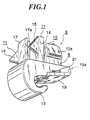
- Fig. 1 is a perspective view of the holder according to the first embodiment of the invention;
- Fig. 2 illustrates the holder with the cover plate open, which is about to be attached to a roof lining in a perspective view;
- Fig. 3 illustrates the holder shown in Fig. 2 in a side view;
- Fig. 4 illustrates the holder with the cover plate closed, which is now attached to the roof lining, in a side view;
- Fig. 5 illustrates the structure of holder in which Fig. 5(A) is a plane view, Fig. 5(B) is a front view, and Fig. 5(C) is a rear view of the holder;
- Fig. 6 illustrates how the holder is supported on the roof lining 6, in which Fig. 6(A) shows the state of temporary attachment, and Fig. 6(B) shows the state of final attachment;
- Fig. 7 illustrates the structure of the insertion having contact projections, in which Fig. 7(A) is a front view, Fig. 7(B) is a right-side view, and Fig. 7(C) is a left-side view;
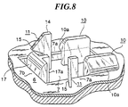
- Fig. 8 illustrates how the elastic stoppers of the holder are engaged with the periphery of the through-hole;
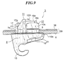
- Fig. 9 illustrates a modification of the holder in a side view;
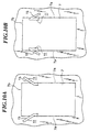
- Fig. 10 illustrates modifications of the wings of the second elastic stoppers in plane views, in which Fig. 10(A) shows the wings, each making an acute angle with respect to its leg, and Fig. 10(B) shows the wings, each making an obtuse angle with respect to its leg;
- Fig. 11 illustrates the holder according to the second invention in perspective views, in which Fig. 11(A) shows the cover plate in the open position, and Fig. 11(B) shows the cover plate in the closed position;
- Fig. 12 is a front view of the holder shown in Fig. 11;
- Fig. 13 is a rear view of the holder shown in Fig. 11;
- Fig. 14 is a plan view of the holder shown in Fig. 11;
- Fig. 15 is a bottom view of the holder shown in Fig. 11;
- Fig. 16 illustrates in left-side views how the holder temporarily attached to the roof lining is finally fixed to the panel board having a through-hole, in which Fig. 16(A) shows the holder immediately before the attachment to the panel board with the cover plate open, and Fig. 16(B) shows the final attachment of the holder with the cover p]ate closed;
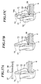
- Fig. 17 illustrates how the elastic stoppers of the holder are inserted into the through-hole, in which Fig. 17(A) shows the elastic stoppers that are going to be inserted into the through-hole, Fig. 17(B) shows the elastic stoppers in temporary contact with the edges of the through-hole, and Fig. 17(C) shows the elastic stoppers in final contact with the edges of the through-hole;
- Fig. 18 illustrates the holder according to the third embodiment of the invention;
- Fig. 19 illustrates the interior of an automobile; and
- Fig. 20 is an enlarged view of the sun visor attached to the roof lining above the driver's sheet.
-
- The invention will now be described in detail in conjunction with the attached drawings.
- Figs. 1 through 10 illustrate a holder with a fastener according to the first embodiment of the invention, which is suitably used to receive the
shaft 26 of a sun visor (shown in Fig. 20) in an automobile. The fastener of this embodiment is inserted in a rectangular through-hole formed in thewall 39 to fix theholder 3 onto thewall 39. Thewall 39 consists of the roof lining 6 and thepanel board 38 in this embodiment. However, the fastener allows theholder 3 to be fixed to any types of boards, panels, and walls. In addition, the structure of the fastener of theholder 3 can be applied to many articles, including holders, retainers, hooks, etc. - In this embodiment, the
holder 3 is made of a synthetic resin. Theholder 3 has abase 8, a portion of which is shaped in ahook 13 for holding theshaft 26 of thesun visor 1. Thehook 13 is curled in a direction opposite to the top face of thebase 8, on which the fastener is formed. Arectangular opening 9 is formed in the center of thebase 8. Recesses extend from the opposingedges 9a of theopening 9 toward the side faces of thebase 8, so that each side face has anopening 21. - A pair of first
elastic stoppers 10 stands upright from the top face of thebase 8, along the opposingsides 9a of theopening 9. A pair of secondelastic stoppers 11 stands upright from the top face of thebase 8, adjacent to the first elastic stoppers. Afront stopper 17 stands upright from the top face of thebase 8 so as to be substantially perpendicular to the first and secondelastic stoppers stoppers - Each of the first
elastic stoppers 10 has aninclined projection 10a shaped in a prism extending outward. Each of the secondelastic stoppers 11 has atriangular wing 15 spreading outward. As is illustrated in Figs. 4, 6 and 8, the fastener of theholder 3 is inserted into a rectangular through-hole 7 formed in thewall 39. The through-hole 7 is defined byedges 7a andshorter edges 7b that is perpendicular to theedges 7a, as shown in Fig. 8. A portion of the bottom faces of theinclined projections 10a of the firstelastic stoppers 10 catch theedges 7a of the through-hole 7. Since eachprojection 10a is shaped in an arrow having an inclined surface, the firstelastic stoppers 10 can be easily inserted into the through-hole 7. The user feels a click when the fastener has been completely inserted in the through-hole 7. - Each of the second
elastic stoppers 11 has aleg 14 and atriangular wing 15 extending from the upper half of theleg 14. Thewings 15 spread slightly outward from theopening 9. Accordingly, thewings 15 of the secondelastic stoppers 11 are not parallel to each other, as clearly shown in Figs. 5, 6, and 8. A portion of the bottom faces of thewings 15, which is near the roots of thewings 15, catch theedges 7a of the rectangular through-hole 7 behind thewall 39, as shown in Figs. 6(A) and 8. Although in these figures the roof lining 6 and thepanel board 38 are put together to form thewall 39, the roof lining 6 may be independently manufactured and sold. In this case, theholder 3 is temporarily attached to the roof lining 6 for shipping and transportation before the roof lining 6 and theholder 3 are finally fixed to thepanel board 38. Because, in the temporary attachment, thewings 15 are engaged with the soft material, i.e., the roof lining 6, a sufficient amount of lap is taken for eachwing 15. - In this embodiment, the bottom face of the
wing 15 is slightly inclined upward as it approaches the vertex of the triangle. This configuration allows thewing 15 to absorb the unevenness of theedges 7a, which is inevitable due to the manufacturing error. The inclined bottom face of thewing 15 also allows the secondelastic stoppers 11 to be removed from the through-hole 7 without difficulty when theholder 3 is detached from thewall 39. - The amount of projection length Δ2, which is referred to as a lap corresponding to the distance from the
edge 7a of the through-hole 7 to the vertex of thewing 15 of the secondelastic stopper 11, is set greater that the lap Δ1, which corresponds to the height of theinclined projection 10a of the firstelastic stopper 10, as shown in Fig. 6 (Δ2 > Δ1). In addition, theinclined projection 10a of the firstelastic stopper 10 is made thicker than the secondelastic stopper 11, so that the rigidity of the firstelastic stopper 10 becomes greater than that of the secondelastic stopper 11. These arrangements allow the fastener of theholder 3 to be smoothly inserted in the through-hole 7, and to securely engage itself with theedges 7a of the through-hole 7 after the insertion. In addition, the slanted bottom faces of theinclined projection 10a and thewing 15 facilitate the removal of theholder 3 from the through-hole 7. - The
base 8 of theholder 3 has acover plate 19, which swings about thecoupling axis 19a. Figs. 1 and 4 illustrate the closed position of thecover plate 19. Figs. 2 and 3 illustrate the open position of thecover plate 19. Thecoupling axis 19a is a thin bendable plate, and it functions both as a coupler and a hinge so that thecover plate 19 pivots about thecoupling axis 19a. The inner face of thecover plate 19 is furnished with aninsertion 12. As thecover plate 19 is closed, the top of theinsertion 12 gets into theopening 9 formed in thebase 8. When thecover plate 19 is completely close, theinsertion 12 is accommodated in theopening 9, as shown in Fig. 4. In this state, the outer faces of theinsertion 12 push the rear faces of the firstelastic stoppers 10, so that theinclined projections 10a are apart from each other. The outward displacement of theinclined projections 10a ensures firm contact with theedges 7a of the through-hole 7. - To be more precise,
contact pieces insertion 12. Each contact piece 16 has a small swell outward, which is to be in contact with one of the firstelastic stoppers 10. As shown in Figs. 1 and 7, thecontact pieces elastic stoppers 10 in turn at different positions. In this embodiment, thecontact piece 16b first comes into contact with the associated firstelastic stopper 10, and then, thecontact piece 16a comes into contact with the otherelastic stopper 10. This arrangement allows theinsertion 12 to be fit into theopening 9 with a less force. - The
front stopper 17 is positioned above thehook 13 of theholder 3. During the insertion of the fastener, the front face of thefront stopper 17 comes into contact with theedge 7b of the through-hole 7, which is substantially perpendicular to theedges 7a. Thefront stopper 17 has arib 17a on the rear face, therib 17a extending along the longitudinal axis of thefront stopper 17, as shown in Figs. 1, 2, and 5. Therib 17a enhances thefront stopper 17. As is obvious from the drawings, therib 17a of thefront stopper 17 is positioned so as not to conflict with thewings 15 of the secondelastic stoppers 11. Thefront stopper 17 prevents theholder 3 from moving toward theedge 7b of the through-hole 7 when a load is applied to theholder 13 during the pivoting motion of the sun visor about theshaft 24. - To temporarily attach the
holder 3 to thewall 39, the first and secondelastic stoppers hole 7, with thecover plate 19 open, as shown in Fig. 3. The bottom faces of theinclined projections 10a of the firstelastic stoppers 10 are in light contact with theedges 7a of the through-hole 7, and thewings 15 of the secondelastic stoppers 11 catch theedges 7a more securely. Thefront stopper 17 is in contact with theedge 7b of the through-hole 7. In this state, theholder 3 is supported in the through-hole 7 of thewall 39 mainly by four elements, namely, two firstelastic stoppers 10 and two secondelastic stoppers 11. The frictional contact between thefront stopper 17 and theedge 7b also slightly contributes to supporting theholder 3. - As has been mentioned above, this arrangement is applicable to the roof lining 6 that is dealt separately from the
panel board 39. In recent years, multiple elements are assembled into a single unit for purposes of reducing the manufacturing cost. It is very likely that the roof lining 6 and theholder 3 are assembled into a single unit, and the roof lining with a holder is shipped and transported. In this case, the temporary, but reliable attachment of theholder 3 to the roof lining 6 allows safe shipment. This feature meets with the needs for so-called modulization. - In order to finally fix the
holder 3 to thewall 39, thecover plate 19 of theholder 3 is closed, with the first and secondelastic stoppers hole 7. The pivoting motion of thecover plate 19 causes theinsertion 12 to be fit into theopening 9 of thebase 8. As theinsertion 12 gets into theopening 9, the projections of thecontact pieces elastic stoppers 10 outward (in a direction that the firstelastic stoppers 10 are apart from each other), as shown in Fig. 6(B). Consequently the bottom faces of theinclined projections 10a of the firstelastic stoppers 10 come into firm contact with theedges 7a of the through-hole 7. When theinsertion 12 is completely inserted into theopening 9, the user feels a click. - Since the rigidity of the first
elastic stoppers 10 is relatively large, theinclined projections 10a of the firstelastic stoppers 10 can firmly catch theedges 7a of the through-hole 7 under the pressure of theinsertion 12. To be more precise, thecontact pieces elastic stoppers 10 outward, and prevents theinsertion 12 from slipping out of theopening 9. These arrangements allow theholder 3 to be reliably secured to thewall 39 to receive the shaft of the sun visor during the actual use. One of the advantages of this structure is that the firstelastic stoppers 10 stand upright from theopening 9 of thebase 8 in the free state, and therefore, they are easily inserted into the through-hole 7. The user does not have to deform the firstelastic stoppers 10 prior to the insertion. The user simply closes thecover plate 19 to cause theinsertion 12 to push the firstelastic stoppers 10 outward. - Once the
insertion 12 is fit into theopening 9, thecontact projections inclined projections 10 to guarantee the engagement between the firstelastic stoppers 10 and the periphery of the through-hole 7. Thefront stopper 17 is now in frictional contact with theedge 7b of the through-hole, which prevents theholder 3 from moving toward theedge 7b. The frictional contact also contributes to support the load applied to theholder 3 when thesun visor 1 is swung about the pivoting shaft. - When removing the
holder 3 from thewall 39 for replacement of the roof lining 6 with a new one, thecover plate 19 is opened to pull theinsertion 12 out of theopening 9. The firstelastic stoppers 10 are released from the firm engagement with theedges 7a, and return to the free state. In the free state, theinclined projections 10a of the first elastic stoppers are now in light contact with theedges 7a of the through-hole 7. Thebase 8 of theholder 3 is pivoted about one of theedges 7a of the through-hole 7 with the roots of the first and second elastic stoppers fulcrums. Then, the first and secondelastic stoppers other edge 7a, and elastically come off from the through-hole 7. Since thewings 15 of the secondelastic stoppers 11, which has a larger amount of projection Δ1, are made of a more elastic material, the secondelastic stoppers 11 can be pulled out of the through-hole 7 without difficulty. If the first and second elastic stoppers on one side have been disengaged from the associatededge 7a of the through-hole 7, the first and second stoppers on the other side come out of the through-hole 7 easily. - The
holder 3 has ahook 13. The thickness of thebase 8 of theholder 3 gets thicker near thehook 13. When thecover plate 19 is closed (with theinsertion 12 fit into theopening 9 of the base 8), the outer face of thecover plate 19 becomes a part of the inner surface of thehook 13. When theshort shaft 26 of thesun visor 1 is moved toward thehook 13, thehook 13 receives theshaft 26 without fail. In the preferred embodiment, a pair ofslit 18 is formed in the inner face of thehook 13 along its width so that the area between the twoslits 18 elastically bends when receiving theshaft 27. With this arrangement, thehook 13 receives theshaft 26 of thesun visor 1 more easily. - When opening the
cover plate 19, the tip of a screwdriver (not shown) is inserted from the recess 21 (Fig. 1) formed on the side face of thebase 8, in order to separate thecontact projections insertion 12 from the firstelastic stoppers 10. By slightly pivoting the screwdriver, a gap is made between thecover plate 19 and thebase 8. Then, the user can open thecover plate 19 by hand. Therecess 21 allows the user to easily open thecover plate 19. - In this embodiment, the
insertion 12 has such dimensions that it can push the firstelastic stopper 10 against theedges 7a of the through-hole 7. However, the size of theinsertion 12 may be increased so that the first and secondelastic stoppers holder 3 is fixed to the roof lining 6 more securely. - Although, in the embodiment, the second
elastic stopper 11 has asingle wing 15, two or more wings may be formed. Thewing 15 makes an obtuse angle with respect to theleg 14 of the secondelastic stopper 11, as shown in Fig. 10(A). However, thewing 15 may be formed so as to make an acute angle with respect to theleg 14, as shown in Fig. 10(B). The configuration shown in Fig. 10(A) is more desirable because the elasticity of the edge of the through-hole 7 increases as it approaches the corner. The through-hole 7 is not necessarily rectangular. It may be an ellipse or an elongated circle. In this case, the outer surfaces of theelastic stoppers hole 7. - Figs. 11 through 17 illustrate a
holder 30 according to the second embodiment of the invention. The same elements as those illustrated in the first embodiment are denoted by the same numerical references, and the explanation for them will be omitted. - In the second embodiment, the
cover plate 19 is positioned behind thehook 13. In the actual use, theholder 30 is attached to the roof lining 6 so that thehook 13 faces the interior of a car, and that thecover plate 19 is located next to the front glass. Since thecover plate 19 is hidden behind thehook 13, the appearance of theholder 30 is improved. - One of the features of the
holder 30 is that atemporary stopper 32 is formed between, the two firstelastic stoppers 10 so as to oppose thefront stopper 17. Another feature is that a noise-absorption tongue 36 is provided to the inner face of thehook 13, as shown in Figs. 12 and 16. - The
temporary stopper 32 comprises aleg 33 standing upright from the top face of thebase 8, anarrow 34 extending downward obliquely from the tip of theleg 33, and astopper piece 35 extending horizontally at the bottom end of thearrow 34. If theholder 30 is attached to the roof lining 6, which is made of soft material, thestopper piece 35 elastically catches the inner surface of the roof lining 6, as shown in Fig. 16(A). The elastic engagement of thestopper piece 35 with the roof lining 6 improves the reliability of assembling theholder 30 and the roof lining 6 into a single unit for shipping. - Figs. 16 and 17 illustrate how the roof lining 6 with the
holder 30 is attached to theceiling panel 38 of the car. First, the fastening structure of theholder 30 is inserted into the throughhole 37 of theceiling panel 38 until the roof lining 6 touches theceiling panel 38, as shown in Figs. 17(A) and 17(B). During the insertion, thecover plate 19 is open, as shown in Fig. 16(A). Thestopper piece 35 of thetemporary stopper 32 is elastically deformed toward theleg 33, and inserted into the through-hole 37 without requiring much force. - Then, the
cover plate 19 is closed, as shown in Figs. 16(B). Theinsertion 12 formed in the inner face of thecover plate 19 is now in perfect fit with theopening 9 of thebase 8. The outer surface of thecover plate 19 becomes a pan of theholder 30, as shown in Fig. 15. Theinsertion 12 pushes the firstelastic stopper 10 outward to bring them into firm contact with the ceiling panel, as shown in Figs. 14 and 17(C). In this state, thefront stopper 17 is in frictional contact with theedge 37b of the through-hole 37 of theceiling panel 38. - The
hook 13 of theholder 30 receives theshaft 26 of thesun visor 1, as shown in Fig. 16(B). Since the noise-absorption tongue 36 is provided to the inner face of thehook 13, it does not make an uncomfortable noise when receiving theshaft 24. - Fig. 18 illustrates the
holder 40 according to the third embodiment of the invention. The same elements as those shown in the first and second embodiments are denoted by the same numerical references, and the explanation for them will be omitted. - The holder has an
arched plate 11A, which connects thelegs 14 of the secondelastic stoppers 11 behind thefront stopper 17. The top end of theplate 11A draws an arc. Thetriangle wings 15 extend from the both sides of theplate 11A, spreading outward not in parallel to each other, so that the bottom faces of thewings 15 catch the edges of the through-hole 7. - The width of the
arched plate 11A is substantially the same as the width of the through-hole 7. Thearched plate 11A functions as a guide when the fastening structure of theholder 40 is inserted into the through-hole 7, which makes attachment of theholder 40 easier. - The
cover plate 19 is located behind thehook 13, as in the second embodiment. As thecover plate 19 is closed, theinsertion 12 gets into theopening 9 behind thearched plate 11A, and thecontact projections elastic stoppers 10 outward. - As has been described above, the holders according to the invention allows easy attachment and easy removal to and from a wall or the like, without requiring much force. The holder can be temporarily or finally attached to the wall, depending on situations. To temporarily attach the holder to a wall, the user simply inserts the fastening structure of the holder into a through-hole formed on the wall, with the cover plate open. To finally fix the holder, the user closes the cover plate. Since the insertion formed to the inner face of the cover plate pushes at least the first elastic stoppers outward as the cover plate is closed, firm engagement between the stoppers and the edges of the through-hole is achieved.
- In order to detach the holder from the wall, the cover plate is opened to pull the insertion out of the opening of the base. The first elastic stoppers return to the regular position, which allows the user to easily detach the holder from the wall. The easy removal, in conjunction with the two-stage attachment (i.e., temporary and final attachment), is practically useful because assembling a holder and a roof lining in a single unit is promoted.
- The front stopper can prevent the holder from shifting along the longitudinal axis of the through-hole. By placing the cover plate behind the hook, the appearance of the holder is improved when the holder is actually attached to the interior of a car. An arched plate for connecting the second elastic stoppers functions as a guide when the fastening structure is inserted in the through-hole, thereby facilitating the insertion.
- It should be noted that, besides those already mentioned above, many modifications and variations may be made without departing from the novel and advantageous features of the present invention. The fastening structure described above can be applied to many other types of holders, retainers, articles, etc. Accordingly, all such modifications and variations are intended to be included within the scope of the appended claims.
Claims (27)
- A fastening structure for fixing an article onto a board via a through-hole formed thereon, the fastening structure comprising:a base having a top face, side faces opposed to each other, and a rear end;an opening formed in the base, the opening having at least two opposing edges;a pair of first elastic stoppers standing upright from the top face of the base so as to oppose to each other and positioned along the edges of the opening, each first elastic stopper having an inclined projection extending outward;a pair of second elastic stoppers standing upright from the top face of the base and positioned next to the first elastic stoppers, each second elastic stopper having a leg and a wing extending from the leg, the wings spreading outward so as not to be parallel to each other;a cover plate attached to the rear end of the base in a pivotable manner, the cover plate swinging between an open position and a closed position; andan insertion extending from the inner surface of the cover plate, the insertion being fit into the opening of the base and pushing at least the first elastic stoppers outward when the cover plate is closed.
- The fastening structure according to claim 1, wherein the cover plate becomes a part of the bottom face of the base when the cover plate is closed.
- The fastening structure according to claim 1, further comprising recesses formed on the side faces of the base, each recess extending inward and communicating with the opening.
- The fastening structure according to claim 1, further comprising a front stopper standing upright from the top face of the base, the front stopper being substantially perpendicular to the first and second elastic stoppers.
- The fastening structure according to claim 4, further comprising a temporary stopper consisting of a leg, an arrow extending obliquely downward from the top of the leg, and a stopper piece extending horizontally at the tip of the lower end of the arrow.
- The fastening structure according to claim 1, further comprising an arched plate connecting the legs of the second elastic stoppers.
- The fastening structure according to claim 1, wherein the insertion has contact pieces, each contact piece pushing the associated first elastic stopper outward when the cover plate is closed.
- The fastening structure according to claim 1, wherein the second elastic stoppers are positioned along the edges of the opening next to the first elastic stoppers, and the insertion pushes both the first and second elastic stoppers when the cover plate is closed.
- The fastening structure according to claim 1, wherein the second elastic stoppers are more elastic than the first elastic stoppers.
- The fastening structure according to claim 1, wherein the lap of the wing of the second elastic stopper is greater than the lap of the inclined projection of the first elastic stopper.
- The fastening structure according to claim 1, wherein the wing of the second elastic stopper makes an acute angle with respect to its leg.
- The fastening structure according to claim 1, wherein the wing of the second elastic stopper make an obtuse angle with respect to its leg.
- The fastening structure according to claim 1, wherein the edges of the opening are substantially straight so that the opening is rectangular.
- The fastening structure according to claim 1, wherein the through-hole formed on the board is a rectangular hole defined by longer edges and shorter edges, and the inclined projections of the first elastic stoppers catch the longer edges of the through-hole when the fastening structure is inserted into the through-hole.
- The fastening structure according to claim 14, wherein the insertion has contact pieces, and the contact pieces pushes the first elastic stoppers outward when the cover plate is closed, so that the inclined projection of the first elastic stoppers come into firm contact with the longer edges of the through-hole.
- The fastening structure according to claim 14, further comprising a front stopper, and wherein the front stopper comes into contact with a shorter edge of the though-hole when the fastening structure is inserted in the through-hole.
- A holder with a fastening structure comprising;a base having a top face, side faces opposed to each other, and a rear end;a hook extending from the base and curling in a direction opposite to the top face of the base;a cover plate attached to the rear end of the base in a pivotable manner, the cover plate swinging between an open position and a closed position,an opening formed in the base, the opening being defined by at least two edges;a pair of first elastic stoppers standing upright from the top face of the base and positioned along the edges of the opening, each first elastic stopper having an inclined projection extending outward;a pair of second elastic stoppers standing upright from the top face of the base and positioned next to the first elastic stoppers, each second elastic stopper having a leg and a wing extending from the leg, the wings spreading outward so as not to be parallel to each other; andan insertion extending from the inner surface of the cover plate, the insertion being fit into the opening of the base and pushing at least the first elastic stoppers outward when the cover plate is closed.
- The holder with a fastening structure according to claim 17, wherein the cover plate smoothly connect with inner surface of the hook when the cover plate is closed.
- The holder with a fastening structure according to claim 17, wherein the cover plate is located behind the hook, and the cover plate smoothly connects with the outer surface of the hook when the cover plate is closed.
- The holder with a fastening structure according to any one of claims 17 through 19, further comprising a noise-absorption tongue that is provided onto the inner surface of the hook.
- The holder with a fastening structure according to claim 17, wherein the insertion has contact pieces, and the contact pieces push the first elastic stoppers outward when the cover plate is closed.
- The holder with a fastening structure according to claim 17, wherein the fastening structure of the holder is inserted in a through-hole formed in a supporting material on which the holder is attached; and
wherein the holder has a temporary attachment mode, in which the holder is temporarily attached to the supporting material with the cover plate open, and a final attachment mode, in which the holder is finally attached to the supporting material with the cover plate closed. - The holder with a fastening structure according to claim 22, wherein the inclined projections of the first elastic stoppers are in light contact with the edges of the through-hole in the temporary attachment mode, and in firm contact with the edges of the through-hole in the final attachment mode under the pressure of the insertion.
- A roof lining with a holder comprising;a lining having a through-hole; anda holder attached to the lining via the through-hole, the holder having a fastening structure that comprises:a base having a top face, side faces opposed to each other, and a rear end;an opening formed in the base, the opening being defined by at least two edges;a pair of first elastic stoppers standing upright from the top face of the base and positioned along the edges of the opening, each first elastic stopper having an inclined projection extending outward;a pair of second elastic stoppers standing upright from the top face of the base and positioned next to the first elastic stoppers, each second elastic stopper having a leg and a wing extending from the leg, the wings spreading outward so as not to be parallel to each other;a cover plate attached to the rear end of the base in a pivotable manner, the cover plate swinging between an open position and a closed position; andan insertion extending from the inner surface of the cover plate, the insertion being fit into the opening of the base and pushing at least the first elastic stoppers outward when the cover plate is closed.
- The roof lining with a holder according to claim 24, wherein the holder is attached to the lining with the cover plate open.
- The roof lining with a holder according to claim 24, wherein the cover plate is closed when the roof lining with a holder is finally fixed to a panel board.
- A fastener comprising:arm means (10) flexible to allow insertion through a through hole in a surface and resilient to engage with an edge of the through hole when inserted; and retainer means (12) disposable in an abutting relationship with said arm means thereby to retain the arm means engaged with said edge.
Applications Claiming Priority (2)
| Application Number | Priority Date | Filing Date | Title |
|---|---|---|---|
| JP11708499 | 1999-04-23 | ||
| JP11708499 | 1999-04-23 |
Publications (2)
| Publication Number | Publication Date |
|---|---|
| EP1046825A2 true EP1046825A2 (en) | 2000-10-25 |
| EP1046825A3 EP1046825A3 (en) | 2002-04-17 |
Family
ID=14703008
Family Applications (1)
| Application Number | Title | Priority Date | Filing Date |
|---|---|---|---|
| EP00303364A Withdrawn EP1046825A3 (en) | 1999-04-23 | 2000-04-20 | Fastening structure for fixing an article on a board via a through-hole, and holder with such a fastening structure |
Country Status (2)
| Country | Link |
|---|---|
| US (1) | US6324732B1 (en) |
| EP (1) | EP1046825A3 (en) |
Cited By (7)
| Publication number | Priority date | Publication date | Assignee | Title |
|---|---|---|---|---|
| EP1174296A3 (en) * | 2000-07-21 | 2002-09-04 | Nifco Inc. | Support bracket for automobile sun visor |
| EP1387091A1 (en) * | 2002-08-02 | 2004-02-04 | Robert Bosch Gmbh | Fastening device |
| WO2005113989A1 (en) * | 2004-05-14 | 2005-12-01 | 3M Innovative Properties Company | Article support |
| ITTO20090944A1 (en) * | 2009-12-01 | 2011-06-02 | Illinois Tool Works | SELF-LOCKING ACCESSORY FOR A VEHICLE BODY PART |
| WO2012062673A1 (en) * | 2010-11-12 | 2012-05-18 | Arcelik Anonim Sirketi | A washer/dryer comprising a connection member |
| DE102012221732A1 (en) | 2012-11-28 | 2014-05-28 | A. Raymond Et Cie | Device for detachable, play-free fastening of an attachment to a carrier part |
| FR3045508A1 (en) * | 2015-12-17 | 2017-06-23 | Renault Sas | ARRANGEMENT OF A DEVICE FOR SUPPORTING A SUN VISOR AXIS ON A PAVILION OF A MOTOR VEHICLE |
Families Citing this family (34)
| Publication number | Priority date | Publication date | Assignee | Title |
|---|---|---|---|---|
| US6450561B2 (en) * | 2000-05-11 | 2002-09-17 | Neo-Ex Lab, Inc. | Attachment devices |
| KR100437629B1 (en) * | 2001-05-23 | 2004-06-25 | (주)대한솔루션 | Assistant Handle Clip for Module Headliner of Automobile |
| US6887197B2 (en) * | 2001-10-05 | 2005-05-03 | Boss Instruments Ltd. | Side loading surgical retractor having offset cavity |
| US6733444B2 (en) * | 2002-04-05 | 2004-05-11 | Burns P. Phillips | Side loading surgical retractor |
| US7287305B2 (en) * | 2002-03-19 | 2007-10-30 | Intier Automotive Inc. | Extruded flexible self-locking trim cover assembly retention clip and method for using same |
| US6829812B2 (en) * | 2002-09-18 | 2004-12-14 | Johnson Controls Technology Company | Grab handle assembly system and method |
| DE10256144A1 (en) * | 2002-11-29 | 2004-06-17 | Newfrey Llc, Newark | Fastening device for an elongated object, in particular wire harness |
| DE10307975A1 (en) * | 2003-02-24 | 2004-09-02 | Behr Gmbh & Co. Kg | clip |
| US7569014B2 (en) * | 2005-09-07 | 2009-08-04 | West Coast Surgical, Llc | Connector for a surgical retractor |
| US7588537B2 (en) * | 2005-09-07 | 2009-09-15 | West Coast Surgical, Llc. | Connector with safety latch for a surgical retractor |
| FR2895939B1 (en) * | 2006-01-09 | 2008-04-11 | Itw De France Soc Par Actions | CROCHET OF RECEPTION OF A JOINT TOURILLON |
| DE102006015515A1 (en) * | 2006-03-31 | 2007-10-04 | Recaro Aircraft Seating Gmbh & Co. Kg | Method for constructing seat especially for aircraft has ratchet grips for rapid assembly |
| DE102006034182A1 (en) * | 2006-07-24 | 2008-02-07 | Siemens Ag | Object e.g. road map, storage compartment for use in motor vehicle, has hook for hanging objects arranged in area of opening, lying on base of compartment in resting position and pivotable into usage position and partially closes opening |
| NO328665B1 (en) * | 2008-04-03 | 2010-04-19 | Opsvik Peter As | Chair fastener |
| DE102008036625B4 (en) | 2008-08-06 | 2023-05-04 | Dr. Ing. H.C. F. Porsche Aktiengesellschaft | Device for the correct positioning of two components in relation to one another |
| DE102009046636A1 (en) * | 2009-11-11 | 2011-05-12 | Atinha Gmbh | Wire network for vehicle seat, comprises frame wire and unit for connecting frame wire, where clip comprises connector for receiving frame wire or transverse wire |
| US8141832B2 (en) | 2010-04-05 | 2012-03-27 | Honda Motor Co., Ltd. | Snap-on hook and cover for sunshade |
| NO334981B1 (en) * | 2010-06-24 | 2014-08-18 | Stokke As | Baby crib for chair |
| US9812684B2 (en) | 2010-11-09 | 2017-11-07 | GM Global Technology Operations LLC | Using elastic averaging for alignment of battery stack, fuel cell stack, or other vehicle assembly |
| US8579010B2 (en) | 2011-03-08 | 2013-11-12 | Honda Motor Co., Ltd | Sunshade hook |
| US8851150B2 (en) * | 2012-08-09 | 2014-10-07 | Honda Motor Co., Ltd. | One-piece slide-on sunshade hook |
| US9403420B2 (en) * | 2012-10-25 | 2016-08-02 | Piolax, Inc. | Sun visor holder |
| US8919856B2 (en) * | 2013-03-15 | 2014-12-30 | Honda Motor Co., Ltd. | Sunshade hook |
| JP6292003B2 (en) * | 2014-04-25 | 2018-03-14 | トヨタ紡織株式会社 | Vehicle seat |
| US9429176B2 (en) * | 2014-06-30 | 2016-08-30 | GM Global Technology Operations LLC | Elastically averaged alignment systems and methods |
| US10220791B2 (en) * | 2014-10-07 | 2019-03-05 | Piolax, Inc. | Component mounting structure |
| US9758110B2 (en) | 2015-01-12 | 2017-09-12 | GM Global Technology Operations LLC | Coupling system |
| WO2017021427A1 (en) * | 2015-08-03 | 2017-02-09 | Johnson Controls Gmbh | Stop for a rail of a longitudinally adjustable seat |
| US9789752B1 (en) | 2016-04-11 | 2017-10-17 | Honda Motor Co., Ltd. | Window shade hook assembly, and methods of use and manufacture thereof |
| JP7134363B2 (en) * | 2019-09-03 | 2022-09-09 | 株式会社パイオラックス | sun visor holder |
| USD1020423S1 (en) * | 2021-05-28 | 2024-04-02 | C. Connor Crook | Storage panel for tools and tool holders |
| KR20230009678A (en) | 2021-07-09 | 2023-01-17 | 현대자동차주식회사 | Hook assembly for door curtain of vehicle |
| KR102871249B1 (en) * | 2022-03-02 | 2025-10-15 | 주식회사 마바산업 | Vehicle sunvisor with tilting structure |
| KR102871247B1 (en) * | 2022-03-02 | 2025-10-15 | 주식회사 마바산업 | Vehicle sun visor |
Citations (1)
| Publication number | Priority date | Publication date | Assignee | Title |
|---|---|---|---|---|
| JPH04110224A (en) | 1990-08-30 | 1992-04-10 | Toyota Motor Corp | Sunvisor holder fitting structure for vehicle |
Family Cites Families (9)
| Publication number | Priority date | Publication date | Assignee | Title |
|---|---|---|---|---|
| JPH0322570Y2 (en) * | 1987-02-17 | 1991-05-16 | ||
| DE4341093A1 (en) * | 1992-12-11 | 1994-06-16 | Volkswagen Ag | Mounting for sun visor for vehicle - has one piece plastics moulded bearing with snap, fitting into mounting hole and secured by clamping wedge |
| DE4326661A1 (en) * | 1993-08-09 | 1995-02-16 | Happich Gmbh Gebr | Counter bearing bracket for vehicle sun visors |
| US5507545A (en) * | 1994-07-05 | 1996-04-16 | Trw Inc. | Visor clip assembly and releasable fastener |
| US5560575A (en) * | 1995-02-21 | 1996-10-01 | Trw Inc. | Support and releasable fastener assembly |
| DE19616051C2 (en) * | 1996-04-23 | 1998-07-02 | Lear Corp | Device for connecting the edge region of a cover material for vehicle seat upholstery with a holder |
| FR2761127B1 (en) * | 1997-03-24 | 1999-06-04 | Itw De France | ARTICLE TO BE FIXED IN THE BLIND AND VEHICLE COMPRISING SAME |
| FR2761422B1 (en) * | 1997-03-27 | 1999-06-18 | Peugeot | DEVICE FOR FIXING ANY ELEMENT, SUCH AS A HANDLE, ON A WALL |
| US5881800A (en) * | 1998-04-03 | 1999-03-16 | Chung; Kuang-Hua | Heat sink fastener |
-
2000
- 2000-04-20 EP EP00303364A patent/EP1046825A3/en not_active Withdrawn
- 2000-04-21 US US09/556,144 patent/US6324732B1/en not_active Expired - Fee Related
Patent Citations (1)
| Publication number | Priority date | Publication date | Assignee | Title |
|---|---|---|---|---|
| JPH04110224A (en) | 1990-08-30 | 1992-04-10 | Toyota Motor Corp | Sunvisor holder fitting structure for vehicle |
Cited By (11)
| Publication number | Priority date | Publication date | Assignee | Title |
|---|---|---|---|---|
| EP1174296A3 (en) * | 2000-07-21 | 2002-09-04 | Nifco Inc. | Support bracket for automobile sun visor |
| EP1387091A1 (en) * | 2002-08-02 | 2004-02-04 | Robert Bosch Gmbh | Fastening device |
| AU2003204918B2 (en) * | 2002-08-02 | 2009-09-17 | Robert Bosch Gmbh | Mounting device |
| WO2005113989A1 (en) * | 2004-05-14 | 2005-12-01 | 3M Innovative Properties Company | Article support |
| CN1985095B (en) * | 2004-05-14 | 2010-11-17 | 3M创新有限公司 | item holder |
| ITTO20090944A1 (en) * | 2009-12-01 | 2011-06-02 | Illinois Tool Works | SELF-LOCKING ACCESSORY FOR A VEHICLE BODY PART |
| WO2011068795A1 (en) * | 2009-12-01 | 2011-06-09 | Illinois Tool Works Inc. | A self-locking automotive accessory for a vehicle body part |
| WO2012062673A1 (en) * | 2010-11-12 | 2012-05-18 | Arcelik Anonim Sirketi | A washer/dryer comprising a connection member |
| DE102012221732A1 (en) | 2012-11-28 | 2014-05-28 | A. Raymond Et Cie | Device for detachable, play-free fastening of an attachment to a carrier part |
| EP2738398A2 (en) | 2012-11-28 | 2014-06-04 | A. Raymond Et Cie | Device for detachably securing an attachment to a support with no play |
| FR3045508A1 (en) * | 2015-12-17 | 2017-06-23 | Renault Sas | ARRANGEMENT OF A DEVICE FOR SUPPORTING A SUN VISOR AXIS ON A PAVILION OF A MOTOR VEHICLE |
Also Published As
| Publication number | Publication date |
|---|---|
| US6324732B1 (en) | 2001-12-04 |
| EP1046825A3 (en) | 2002-04-17 |
Similar Documents
| Publication | Publication Date | Title |
|---|---|---|
| US6324732B1 (en) | Fastening structure for fixing an article on board VIA through-hole, and holder with fastening structure | |
| US5524370A (en) | System for attaching a backing plate to a picture frame structure | |
| US7458548B2 (en) | Removable shelf locking system | |
| US5778575A (en) | Garment hanger hook size system | |
| JP6851884B2 (en) | clip | |
| US7178770B2 (en) | Article support device | |
| US8333284B2 (en) | Clip for convertible card row | |
| US20070257165A1 (en) | Article support device mountable with stretch releasing adhesive | |
| JPH10512943A (en) | Mounting clip | |
| US20100320347A1 (en) | Mounting structure for functional component | |
| US4217710A (en) | Frameless support for pictures | |
| US6513672B1 (en) | Hinged jewelry case with glueless fabric insert | |
| JP6266847B1 (en) | Wall mountable assembly and method of use | |
| JP2001029201A (en) | Foldable cup holder | |
| EP1057670A1 (en) | Fixing clip for fixing articles onto panel and interior module with fixing clip | |
| JP3232200B2 (en) | Fastening clip and fastening structure of two members | |
| JP2001003911A (en) | Buckle | |
| JPH11129832A (en) | Roof molding clip | |
| JP2557965Y2 (en) | Temporary fasteners for shelves in furniture | |
| US20050067547A1 (en) | Visor assembly | |
| CN115384281B (en) | Sun visor hook | |
| CN214729299U (en) | Quick release bracket assembly | |
| JP7134363B2 (en) | sun visor holder | |
| JPH0539208Y2 (en) | ||
| JPH0622577Y2 (en) | Clip for belt molding of automobile door |
Legal Events
| Date | Code | Title | Description |
|---|---|---|---|
| PUAI | Public reference made under article 153(3) epc to a published international application that has entered the european phase |
Free format text: ORIGINAL CODE: 0009012 |
|
| AK | Designated contracting states |
Kind code of ref document: A2 Designated state(s): AT BE CH CY DE DK ES FI FR GB GR IE IT LI LU MC NL PT SE |
|
| AX | Request for extension of the european patent |
Free format text: AL;LT;LV;MK;RO;SI |
|
| PUAL | Search report despatched |
Free format text: ORIGINAL CODE: 0009013 |
|
| AK | Designated contracting states |
Kind code of ref document: A3 Designated state(s): AT BE CH CY DE DK ES FI FR GB GR IE IT LI LU MC NL PT SE |
|
| AX | Request for extension of the european patent |
Free format text: AL;LT;LV;MK;RO;SI |
|
| RIC1 | Information provided on ipc code assigned before grant |
Free format text: 7F 16B 19/10 A, 7B 60J 3/02 B, 7F 16B 5/06 B |
|
| 17P | Request for examination filed |
Effective date: 20020924 |
|
| AKX | Designation fees paid |
Free format text: AT BE CH CY DE DK ES FI FR GB GR IE IT LI LU MC NL PT SE |
|
| GRAP | Despatch of communication of intention to grant a patent |
Free format text: ORIGINAL CODE: EPIDOSNIGR1 |
|
| STAA | Information on the status of an ep patent application or granted ep patent |
Free format text: STATUS: THE APPLICATION IS DEEMED TO BE WITHDRAWN |
|
| 18D | Application deemed to be withdrawn |
Effective date: 20061027 |