EP1046787A2 - Turbine inner shell heating and cooling flow circuit - Google Patents
Turbine inner shell heating and cooling flow circuit Download PDFInfo
- Publication number
- EP1046787A2 EP1046787A2 EP20000302670 EP00302670A EP1046787A2 EP 1046787 A2 EP1046787 A2 EP 1046787A2 EP 20000302670 EP20000302670 EP 20000302670 EP 00302670 A EP00302670 A EP 00302670A EP 1046787 A2 EP1046787 A2 EP 1046787A2
- Authority
- EP
- European Patent Office
- Prior art keywords
- inner shell
- passage
- thermal medium
- turbine
- section
- Prior art date
- Legal status (The legal status is an assumption and is not a legal conclusion. Google has not performed a legal analysis and makes no representation as to the accuracy of the status listed.)
- Granted
Links
Images


Classifications
-
- F—MECHANICAL ENGINEERING; LIGHTING; HEATING; WEAPONS; BLASTING
- F01—MACHINES OR ENGINES IN GENERAL; ENGINE PLANTS IN GENERAL; STEAM ENGINES
- F01D—NON-POSITIVE DISPLACEMENT MACHINES OR ENGINES, e.g. STEAM TURBINES
- F01D11/00—Preventing or minimising internal leakage of working-fluid, e.g. between stages
- F01D11/08—Preventing or minimising internal leakage of working-fluid, e.g. between stages for sealing space between rotor blade tips and stator
- F01D11/14—Adjusting or regulating tip-clearance, i.e. distance between rotor-blade tips and stator casing
- F01D11/20—Actively adjusting tip-clearance
- F01D11/24—Actively adjusting tip-clearance by selectively cooling-heating stator or rotor components
-
- F—MECHANICAL ENGINEERING; LIGHTING; HEATING; WEAPONS; BLASTING
- F01—MACHINES OR ENGINES IN GENERAL; ENGINE PLANTS IN GENERAL; STEAM ENGINES
- F01D—NON-POSITIVE DISPLACEMENT MACHINES OR ENGINES, e.g. STEAM TURBINES
- F01D25/00—Component parts, details, or accessories, not provided for in, or of interest apart from, other groups
- F01D25/08—Cooling; Heating; Heat-insulation
-
- F—MECHANICAL ENGINEERING; LIGHTING; HEATING; WEAPONS; BLASTING
- F01—MACHINES OR ENGINES IN GENERAL; ENGINE PLANTS IN GENERAL; STEAM ENGINES
- F01D—NON-POSITIVE DISPLACEMENT MACHINES OR ENGINES, e.g. STEAM TURBINES
- F01D25/00—Component parts, details, or accessories, not provided for in, or of interest apart from, other groups
- F01D25/24—Casings; Casing parts, e.g. diaphragms, casing fastenings
- F01D25/26—Double casings; Measures against temperature strain in casings
-
- F—MECHANICAL ENGINEERING; LIGHTING; HEATING; WEAPONS; BLASTING
- F02—COMBUSTION ENGINES; HOT-GAS OR COMBUSTION-PRODUCT ENGINE PLANTS
- F02C—GAS-TURBINE PLANTS; AIR INTAKES FOR JET-PROPULSION PLANTS; CONTROLLING FUEL SUPPLY IN AIR-BREATHING JET-PROPULSION PLANTS
- F02C7/00—Features, components parts, details or accessories, not provided for in, or of interest apart form groups F02C1/00 - F02C6/00; Air intakes for jet-propulsion plants
- F02C7/12—Cooling of plants
- F02C7/16—Cooling of plants characterised by cooling medium
- F02C7/18—Cooling of plants characterised by cooling medium the medium being gaseous, e.g. air
Definitions
- the present invention relates generally to gas turbines, particularly to land-based, i.e., industrial gas turbines employing closed-circuit steam or air cooling of hot gas path components and more particularly to a gas turbine having inner and outer turbine shells constructed to provide positive bucket tip clearance control.
- the upper outer shell half and each inner shell half are individually removable from the turbine without removal of the rotor to enable access to the hot gas path components for maintenance and repair.
- the inner shell is supported by pins extending between the inner and outer shells in a manner preventing circumferential, axial and radial movement of the shells relative to one another while enabling radial expansion and contraction of the inner shell relative to the outer shell for controlling clearance between the shrouds and the bucket tips.
- the clearance control system includes a pair of plenums in each of the inner shell halves and which plenums are connected one to the other by a passageway.
- the first or forward plenum overlying the first-stage shrouds and bucket tips has an inlet for receiving cooling air, the cooling air flowing circumferentially about the plenum to the mid-line of the inner shell half.
- Axially extending passages along diametrically opposite mid-lines extend from the forward plenum back to a similar circumferentially extending aft plenum overlying the second-stage shrouds and buckets.
- An outlet is provided in the aft plenum.
- cooling air at steady-state operation from an external air source is supplied to the first-stage plenum inlet for flow about the plenum, axially along the mid-line and about the second-stage plenum to the outlet.
- the inner shell may contract and expand in a radial direction in response to flow of the thermal medium. Consequently, by controlling the thermal expansion or contraction in a radial direction of the inner shell relative to the tips of the buckets of the first and second stages, tip clearance control is afforded.
- the advanced gas turbine design includes an inner shell having inner shell halves each having a forward and aft section containing plenums communicating with one another such that a thermal medium may be supplied to one section for flow axially to the other section and return to the one section.
- the thermal medium is supplied via an inlet for circumferential flow in a first plenum of the first inner shell half section and for flow generally axially along a first set of passageways in communication with a first plenum of the second section for circumferential flow therein.
- the first plenum of the second section communicates with a second plenum of the second section whereby the flow reverses direction for flow circumferentially about the second section and then along a second set of axial passageways along the mid-line of the inner shell half to the second plenum of the first section.
- the flow enters circumferentially extending second passage portions in the second plenum of the first section for exit and return to the thermal medium supply.
- the thermal medium supply comprises an auxiliary thermal medium source independent of turbine operation whereby the temperature of the thermal medium can be controlled independently of the turbine.
- the inner shell can be expanded at a rate at least equal to or greater than the thermal expansion rate of the rotor and buckets during start-up to prevent contact between the turbine tips and the shrouds and to preclude a rate of contraction of the inner shell less than the rate of contraction of the rotor and buckets to avoid contact between the turbine tips and the shrouds during shutdown.
- the temperature of the thermal medium is controlled to expand or contract the inner shell to minimize the clearance between the shrouds and the bucket tips, affording enhanced turbine efficiency.
- a method of operating a turbine having a rotor including axially spaced buckets carried thereby forming parts of turbine stages, an outer containment shell, an inner shell about the rotor including nozzles carried thereby forming other parts of the turbine stages, the inner shell including axially spaced sections and shrouds carried by the sections about the respective tips of the buckets of the stages, and a passage formed in the inner shell for flow of a thermal medium to control thermal movement of the inner shell, comprising the steps of forming at least partially circumferentially extending first portions of the passage in the sections of the inner shell substantially at each axial location of the buckets of the respective stages, providing a first passageway in the inner shell connecting the first passage portions to one another, flowing a thermal medium through (i) a first passage portion of one section, (ii) the first passageway and (iii) first passage portion of another section, forming at least partially circumferentially extending second portions of the passage in the sections of the inner
- a method of operating a turbine having a rotor including axially spaced buckets carried thereby forming parts of turbine stages, an outer containment shell, an inner shell about the rotor including nozzles carried thereby forming other parts of the turbine stages and shrouds about the respective tips of the buckets of the stages, and a passage formed in the inner shell for flow of a thermal medium to control thermal movement of the inner shell, comprising the steps of flowing a thermal medium serially (i) through passage portions of the inner shell at a first axial location corresponding in part to an axial location of the second stage of said turbine, (ii) forwardly along the inner shell from the first axial location to passage portions of the inner shell at a second location corresponding in part to an axial location of a first stage of the turbine and (iii) rearwardly along the inner shell from the second axial location to passage portions of the inner shell at the first axial locations to control the thermal radial expansion and contraction of the inner shell
- the turbine includes a rotor 12, only a portion of which is illustrated, and which comprises turbine wheels 14, 16 and 18, each carrying a circular array of buckets, the buckets 20 and 22 for wheels 14 and 16 being illustrated.
- Spacers or disks 24, 26 are interposed between the wheels and the stack-up of wheels and spacers are bolted together by bolts 26 to form the rotor 12.
- Nozzles are likewise arranged in circumferential arrays, alternating with the buckets of the wheels, nozzles 28, 30 and 32 being illustrated.
- the first stage of the turbine comprises nozzles 28 and buckets 20, the second stage, nozzles 30 and buckets 22, the third stage, nozzles 32 and buckets for wheel 18, and so on, depending upon the number of stages of the gas turbine.
- the gas turbine includes an outer structural containment shell 34 and an inner shell 36.
- Each outer shell and inner shell is formed in semi-circular sections joined along a horizontal mid-line, the upper halves of the outer and inner shells being illustrated.
- the inner shell 36 includes forward and aft shell sections 38 and 40, respectively, mounted for radial contraction and expansion relative to the outer shell 34 by pins 37.
- An arrangement of pins for mounting the inner shell and outer shell to one another is described in U.S. Patent No. 5,685,693.
- each of the inner and outer shells is comprised of shell halves extending to a horizontal mid-line M where the upper and lower outer shell halves 34U and 34L are bolted to one another and the upper and lower inner shell halves 36U and 36L are secured to one another.
- the aft section 40 includes a pair of axially spaced circumferentially extending first and second passage portions 46 and 48, respectively.
- a thermal medium inlet 50 ( Figure 4) lies in communication with the plenum or passage portion 46 by way of a hollow spoolie 52 ( Figure 1), in turn in communication with a thermal medium source, described below.
- the first and second passage portions 46 and 48 extend circumferentially about the aft section 40 to adjacent the mid-line of the inner shell half.
- the inlet 50 preferably is provided medially of the split line for the inner shell half.
- a spent cooling thermal medium outlet 54 ( Figure 4) lies in communication with the second passage portion 48 of the aft inner shell section 40 for returning spent cooling medium to the external source.
- the first passage portion 46 of the aft inner shell section 40 communicates with a pair of first passageways 56 extending along the split line of the inner shell half axially forwardly for communication with a first passage portion 58 of the forward inner shell section 38.
- the first passage portion 58 of the forward section 38 extends circumferentially from the mid-line passages 56 to intermediate locations in communication with second passage portions 60 of the forward section 38 via crossover paths 62 and 64 ( Figure 4).
- the second passage portions 60 of the forward section 38 extend from crossover paths 62 and 64 to the mid-line of the inner shell half to lie in communication with axially rearwardly extending second passageways 68, in turn in communication with the second passage portions 48 of the aft section 40.
- the second passage portions 48 lie in communication with the outlet 54.
- an external or off-turbine device for supplying cooling or heating air to the inner shell, depending upon the operating conditions of the turbine.
- a compressor 70 with associated heat exchangers 72 and 74 for selectively cooling and heating the air.
- heated air may be supplied from the heater 72 to the inlet 50 for circulation of heated air in the various passages of the inner shell halves to radially expand the inner shell and hence displace the shrouds radially further outwardly than the tips of the buckets.
- the inner shell thus heats up at a greater rate than the rotor to ensure that adequate clearance is maintained between the shrouds and the bucket tips during startup.
- the temperature of the air supplied the inner shell can be adjusted to contract or expand the inner shell relative to the bucket tips thereby to afford a minimum clearance between the shrouds and bucket tips and enhance the efficiency of the turbine operation.
- the temperature of the thermal medium can be adjusted so that a controlled tip clearance during shutdown is maintained.
Landscapes
- Engineering & Computer Science (AREA)
- Mechanical Engineering (AREA)
- General Engineering & Computer Science (AREA)
- Chemical & Material Sciences (AREA)
- Combustion & Propulsion (AREA)
- Turbine Rotor Nozzle Sealing (AREA)
Abstract
Description
- The present invention relates generally to gas turbines, particularly to land-based, i.e., industrial gas turbines employing closed-circuit steam or air cooling of hot gas path components and more particularly to a gas turbine having inner and outer turbine shells constructed to provide positive bucket tip clearance control.
- In prior U.S. Patent No. 5,685,693, of common assignee herewith, there is disclosed a land-based, i.e., industrial gas turbine having a turbine outer shell surrounding an inner shell supporting non-rotational parts of certain of the stages. Particularly, the inner shell supports the first and second-stage nozzles, as well as the first and second-stage shrouds. The outer shell directly supports the nozzles and shrouds of additional stages. It will be appreciated that each of the inner and outer shells is formed in circumferentially extending sections about the rotor aids, preferably in two circumferential halves (upper and lower) of 180° each. The upper outer shell half and each inner shell half are individually removable from the turbine without removal of the rotor to enable access to the hot gas path components for maintenance and repair. In the above patent, the inner shell is supported by pins extending between the inner and outer shells in a manner preventing circumferential, axial and radial movement of the shells relative to one another while enabling radial expansion and contraction of the inner shell relative to the outer shell for controlling clearance between the shrouds and the bucket tips.
- In the above-noted patent, the clearance control system includes a pair of plenums in each of the inner shell halves and which plenums are connected one to the other by a passageway. Particularly, for each inner shell half, the first or forward plenum overlying the first-stage shrouds and bucket tips has an inlet for receiving cooling air, the cooling air flowing circumferentially about the plenum to the mid-line of the inner shell half. Axially extending passages along diametrically opposite mid-lines extend from the forward plenum back to a similar circumferentially extending aft plenum overlying the second-stage shrouds and buckets. An outlet is provided in the aft plenum. Thus, cooling air at steady-state operation from an external air source is supplied to the first-stage plenum inlet for flow about the plenum, axially along the mid-line and about the second-stage plenum to the outlet. It will be appreciated that by flowing a thermal medium in the described thermal circuit, the inner shell may contract and expand in a radial direction in response to flow of the thermal medium. Consequently, by controlling the thermal expansion or contraction in a radial direction of the inner shell relative to the tips of the buckets of the first and second stages, tip clearance control is afforded. With the advent of a further advanced gas turbine design by assignee, there has, however, been demonstrated a need for an enhanced inner shell cooling circuit.
- In accordance with a preferred embodiment of the present invention, the advanced gas turbine design includes an inner shell having inner shell halves each having a forward and aft section containing plenums communicating with one another such that a thermal medium may be supplied to one section for flow axially to the other section and return to the one section. Particularly, for each inner shell half, the thermal medium is supplied via an inlet for circumferential flow in a first plenum of the first inner shell half section and for flow generally axially along a first set of passageways in communication with a first plenum of the second section for circumferential flow therein. The first plenum of the second section communicates with a second plenum of the second section whereby the flow reverses direction for flow circumferentially about the second section and then along a second set of axial passageways along the mid-line of the inner shell half to the second plenum of the first section. The flow enters circumferentially extending second passage portions in the second plenum of the first section for exit and return to the thermal medium supply.
- Preferably, the thermal medium supply comprises an auxiliary thermal medium source independent of turbine operation whereby the temperature of the thermal medium can be controlled independently of the turbine. By flowing the thermal medium in the described circuit, the inner shell can be expanded at a rate at least equal to or greater than the thermal expansion rate of the rotor and buckets during start-up to prevent contact between the turbine tips and the shrouds and to preclude a rate of contraction of the inner shell less than the rate of contraction of the rotor and buckets to avoid contact between the turbine tips and the shrouds during shutdown. During steady-state operation, the temperature of the thermal medium is controlled to expand or contract the inner shell to minimize the clearance between the shrouds and the bucket tips, affording enhanced turbine efficiency.
- In a preferred embodiment according to the present invention, there is provided a method of operating a turbine having a rotor including axially spaced buckets carried thereby forming parts of turbine stages, an outer containment shell, an inner shell about the rotor including nozzles carried thereby forming other parts of the turbine stages, the inner shell including axially spaced sections and shrouds carried by the sections about the respective tips of the buckets of the stages, and a passage formed in the inner shell for flow of a thermal medium to control thermal movement of the inner shell, comprising the steps of forming at least partially circumferentially extending first portions of the passage in the sections of the inner shell substantially at each axial location of the buckets of the respective stages, providing a first passageway in the inner shell connecting the first passage portions to one another, flowing a thermal medium through (i) a first passage portion of one section, (ii) the first passageway and (iii) first passage portion of another section, forming at least partially circumferentially extending second portions of the passage in the sections of the inner shell substantially at each axial location of the buckets of the respective stages, providing a second passageway in the inner shell connecting the second passage portions to one another, connecting the first passage portion of another section with the second passage portion of another section for flowing the thermal medium therebetween and flowing the thermal medium through (i) the second passage portion of another section, (ii) the second passageway and (iii) the second passage portion of one section, thereby controlling the thermal radial expansion and contraction of the inner shell and the clearance between tips of the buckets and shrouds of each stage.
- In a further preferred embodiment according to the present invention, there is provided a method of operating a turbine having a rotor including axially spaced buckets carried thereby forming parts of turbine stages, an outer containment shell, an inner shell about the rotor including nozzles carried thereby forming other parts of the turbine stages and shrouds about the respective tips of the buckets of the stages, and a passage formed in the inner shell for flow of a thermal medium to control thermal movement of the inner shell, comprising the steps of flowing a thermal medium serially (i) through passage portions of the inner shell at a first axial location corresponding in part to an axial location of the second stage of said turbine, (ii) forwardly along the inner shell from the first axial location to passage portions of the inner shell at a second location corresponding in part to an axial location of a first stage of the turbine and (iii) rearwardly along the inner shell from the second axial location to passage portions of the inner shell at the first axial locations to control the thermal radial expansion and contraction of the inner shell and the clearance between the tips of the buckets and shrouds of each first and second stages.
- The invention will now be described in greater detail, by way of example, with reference to the drawings, in which:
- FIGURE 1 is a fragmentary cross-sectional view through a portion of a gas turbine illustrating portions of the inner and outer shells;
- FIGURE 2 is an enlarged cross-sectional view of a portion of the inner shell;
- FIGURE 3 is a schematic view taken along an axial plane illustrating the location of the pin connections between the inner and outer shells;
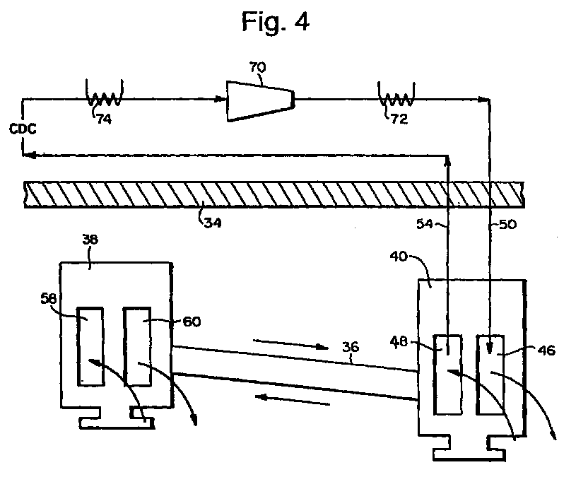
- FIGURE 4 is a schematic diagram illustrating the flow circuit for flowing a thermal medium from an external source to and from the inner shell; and
- FIGURE 5 is a schematic illustration of the flow circuit for the inner shell.
-
- Referring now to the drawings, particularly to Figure 1, there is illustrated a portion of a gas turbine incorporating the present invention. The turbine includes a
rotor 12, only a portion of which is illustrated, and which comprisesturbine wheels buckets wheels disks bolts 26 to form therotor 12. Nozzles are likewise arranged in circumferential arrays, alternating with the buckets of the wheels,nozzles nozzles 28 andbuckets 20, the second stage,nozzles 30 andbuckets 22, the third stage,nozzles 32 and buckets forwheel 18, and so on, depending upon the number of stages of the gas turbine. - The gas turbine includes an outer
structural containment shell 34 and aninner shell 36. Each outer shell and inner shell is formed in semi-circular sections joined along a horizontal mid-line, the upper halves of the outer and inner shells being illustrated. Theinner shell 36 includes forward andaft shell sections outer shell 34 bypins 37. An arrangement of pins for mounting the inner shell and outer shell to one another is described in U.S. Patent No. 5,685,693.
Suffice to say that the inner shell may expand and contract radially, e.g., in the directions of the arrows of Figure 3 in a controlled manner relative to the rotor for adjusting the clearance between theshrouds respective buckets outer shell halves inner shell halves - The
aft section 40 includes a pair of axially spaced circumferentially extending first andsecond passage portions passage portion 46 by way of a hollow spoolie 52 (Figure 1), in turn in communication with a thermal medium source, described below. It will be appreciated that the first andsecond passage portions aft section 40 to adjacent the mid-line of the inner shell half. Theinlet 50 preferably is provided medially of the split line for the inner shell half. A spent cooling thermal medium outlet 54 (Figure 4) lies in communication with thesecond passage portion 48 of the aftinner shell section 40 for returning spent cooling medium to the external source. - The
first passage portion 46 of the aftinner shell section 40 communicates with a pair offirst passageways 56 extending along the split line of the inner shell half axially forwardly for communication with afirst passage portion 58 of the forwardinner shell section 38. Thefirst passage portion 58 of theforward section 38 extends circumferentially from themid-line passages 56 to intermediate locations in communication withsecond passage portions 60 of theforward section 38 viacrossover paths 62 and 64 (Figure 4). Thesecond passage portions 60 of theforward section 38 extend fromcrossover paths second passageways 68, in turn in communication with thesecond passage portions 48 of theaft section 40. As will be recalled, thesecond passage portions 48 lie in communication with theoutlet 54. - Referring now to Figure 3, there is illustrated an external or off-turbine device for supplying cooling or heating air to the inner shell, depending upon the operating conditions of the turbine. For example, there may be provided on an off-turbine skid, and a
compressor 70 with associatedheat exchangers 72 and 74 for selectively cooling and heating the air. Thus, for example, during turbine startup, heated air may be supplied from theheater 72 to theinlet 50 for circulation of heated air in the various passages of the inner shell halves to radially expand the inner shell and hence displace the shrouds radially further outwardly than the tips of the buckets. It will be appreciated that the inner shell thus heats up at a greater rate than the rotor to ensure that adequate clearance is maintained between the shrouds and the bucket tips during startup. In steady-state operations, the temperature of the air supplied the inner shell can be adjusted to contract or expand the inner shell relative to the bucket tips thereby to afford a minimum clearance between the shrouds and bucket tips and enhance the efficiency of the turbine operation. During turbine shutdown, it is important to maintain the rate of contraction of the inner shell less than the rate of contraction of the rotor and buckets to avoid contact between the turbine lips and the shrouds. To that end, the temperature of the thermal medium can be adjusted so that a controlled tip clearance during shutdown is maintained.
Claims (12)
- A method of operating a turbine having a rotor (12) including axially spaced buckets (20, 22) carried thereby forming parts of turbine stages, an outer containment shell (34), an inner shell (36) about the rotor including nozzles (28, 30, 32) carried thereby forming other parts of said turbine stages, said inner shell including axially spaced sections (38, 40) and shrouds (42, 44) carried by said sections about the respective tips of said buckets of said stages, and a passage (46, 56, 58, 62, 60, 68, 48) formed in said inner shell for flow of a thermal medium to control thermal movement of said inner shell, comprising the steps of:forming at least partially circumferentially extending first portions (46, 58) of said passage in said sections of said inner shell substantially at each axial location of the buckets of the respective stages;providing a first passageway (56) in said inner shell connecting the first passage portions to one another;flowing a thermal medium through (i) a first passage portion (46) of one section, (ii) said first passageway (56) and (iii) first passage portion (59) of another section;forming at least partially circumferentially extending second portions (60, 48) of said passage in said sections of said inner shell substantially at each axial location of the buckets of the respective stages;providing a second passageway (68) in said inner shell connecting the second passage portions to one another;connecting the first passage portion (58) of said another section with the second passage portion (60) of said another section for flowing the thermal medium therebetween; andflowing the thermal medium through (i) said second passage portion (60) of said another section, (ii) said second passageway (68) and (iii) said second passage portion (48) of said one section;thereby controlling the thermal radial expansion and contraction of said inner shell and the clearance between tips of the buckets and shrouds of each stage.
- A method according to Claim 1 wherein said one section lies at an axial location corresponding to a second stage of the turbine and said another section lies at an axial location corresponding to a first stage of the turbine, and flowing the thermal medium serially from said second section to said first section and back to said second section.
- A method according to Claim 1 or 2, including connecting said inner shell and said outer shell to one another to preclude radial and circumferential movement of said inner shell relative to said outer shell and enable thermal radial expansion and contraction of said inner shell relative to said outer shell.
- A method according to Claim 1, 2 or 3, including operating the turbine in a steady-state condition, and controlling the temperature of the thermal medium during the steady-state operating condition to control the clearance between the bucket tips and the shrouds.
- A method according to any preceding claim, including providing a thermal medium source independent of said turbine operation for controlling the temperature of the thermal medium.
- A method according to any preceding claim including providing a closed circuit (50, 54, 70, 72, 74) for supplying the thermal medium between the source and the passage.
- A method according to any preceding claim including during shutdown of the turbine, controlling the temperature of the thermal medium to preclude a rate of contraction of the inner shell less than the rate of contraction of the rotor and buckets to avoid contact between the turbine tips and the shrouds.
- A method according to any preceding claim including during turbine startup, controlling the temperature of the thermal medium to thermally expand the inner shell at a rate at least equal to or greater than the thermal expansion rate of the rotor and buckets to prevent contact between the turbine tips and the shrouds.
- A method according to any preceding claim including providing an inlet (50) in communication with said passage and connected between said inner and outer shells for receiving the thermal medium from a source external to said turbine, and providing an outlet (54) in communication with said passage and connected between said inner and outer shells for exhausting the thermal medium from the turbine.
- A method according to any preceding claim wherein said inner shell includes a pair of inner shell halves (36U, 36L) defining a mid-line between said halves, said passage being disposed in one of said inner shell halves, providing said first passage portion (46) of said one section about said one inner shell half substantially to said mid-line thereof providing a pair of first passageway portions (56) of said first passageway generally axially along said mid-line, said first passage portion (58) of said another section forn-ting a pair of paths extending generally from the mid-line of said inner shell half in communication with said pair of first passageway portions, respectively, for flowing the thermal medium substantially about the inner shell halt providing communication between said pair of first passage portion paths and a pair of second passage portions (60) of said passage in said another section, providing a pair of second passageway portions (68) of said second passageway generally extending along said mid-line of said inner shell half and in communication with said second passage portions (48) of said another section and said second passage portions of said one section, providing a thermal medium inlet (50) to said first passage portions of said one section and providing a thermal medium outlet (54) for said second passage portions of said one section whereby said passage forms a closed circuit within said inner shell half.
- A method of operating a turbine having a rotor (12) including axially spaced buckets (20, 22) carried thereby forming parts of turbine stages, an outer containment shell (34), an inner shell (36) about the rotor including nozzles (28, 30, 32) carried thereby forming other parts of said turbine stages and shrouds about the respective tips of said buckets of said stages, and a passage (46, 56, 59, 62, 60, 68, 48) formed in said inner shell for flow of a thermal medium to control thermal movement of said inner shell, comprising the steps of:flowing a thermal medium serially (i) through passage portions (46) of the inner shell at a first axial location corresponding in part to an axial location of the second stage of said turbine, (ii) forwardly (56) along said inner shell from said first axial location to passage portions (58, 60) of said inner shell at a second location corresponding in part to an axial location of a first stage of the turbine and (iii) rearwardly (68) along said inner shell from said second axial location to passage portions (48) of said inner shell at said first axial locations to control the thermal radial expansion and contraction of said inner shell and the clearance between the tips of the buckets and shrouds of each said first and second stages.
- A method according to Claim 11 wherein said inner shell includes a pair of inner shell halves defining a mid-line between said halves, providing an inlet (50) for the thermal medium to said passage portions at said first axial location, splitting the flow of thermal medium from said inlet along arcuate passage portions along said inner shell at said first axial location, flowing the thermal medium from said arcuate flow portions along first plural passageways (56), respectively, to said second axial location and returning the thermal medium from said passage portions (58, 60) at said second axial location along second plural passageway portions (68) to said passage portions at said first axial location and providing an outlet (54) for receiving the thermal medium from said passage portions at said first axial location for flow outwardly of said inner shell.
Applications Claiming Priority (2)
| Application Number | Priority Date | Filing Date | Title |
|---|---|---|---|
| US29840099A | 1999-04-23 | 1999-04-23 | |
| US298400 | 1999-04-23 |
Publications (3)
| Publication Number | Publication Date |
|---|---|
| EP1046787A2 true EP1046787A2 (en) | 2000-10-25 |
| EP1046787A3 EP1046787A3 (en) | 2002-08-28 |
| EP1046787B1 EP1046787B1 (en) | 2006-06-07 |
Family
ID=23150346
Family Applications (1)
| Application Number | Title | Priority Date | Filing Date |
|---|---|---|---|
| EP00302670A Expired - Lifetime EP1046787B1 (en) | 1999-04-23 | 2000-03-30 | Turbine inner shell heating and cooling flow circuit |
Country Status (5)
| Country | Link |
|---|---|
| US (1) | US6422807B1 (en) |
| EP (1) | EP1046787B1 (en) |
| JP (1) | JP4489243B2 (en) |
| KR (1) | KR20000071649A (en) |
| DE (1) | DE60028446T2 (en) |
Cited By (10)
| Publication number | Priority date | Publication date | Assignee | Title |
|---|---|---|---|---|
| KR20000071649A (en) * | 1999-04-23 | 2000-11-25 | 제이 엘. 차스킨, 버나드 스나이더, 아더엠. 킹 | Turbine inner shell heating and cooling flow circuit |
| FR2828908A1 (en) * | 2001-08-23 | 2003-02-28 | Snecma Moteurs | Method of controlling play in gas turbine high pressure stage involves flowing cold air and hot gas across stator ring casing to control diameter |
| EP1239117A3 (en) * | 2001-02-16 | 2004-01-14 | Mitsubishi Heavy Industries, Ltd. | Gas turbine combustor transition piece outlet structure, transition piece, combustor and gas turbine |
| EP1219789A3 (en) * | 2000-12-23 | 2004-02-04 | ALSTOM (Switzerland) Ltd | System and method for the cooling of a turbomachine casing |
| EP2048367A1 (en) * | 2007-10-09 | 2009-04-15 | Siemens Aktiengesellschaft | Casing with cooling device for a process gas turbo compressor |
| EP2351912A1 (en) * | 2010-01-12 | 2011-08-03 | Siemens Aktiengesellschaft | Turbine with heating system, and corresponding solar power plant and operating method |
| CN102444478A (en) * | 2010-10-12 | 2012-05-09 | 通用电气公司 | System and method for turbine compartment ventilation |
| CN101709673B (en) * | 2008-09-12 | 2014-06-11 | 通用电气公司 | Device and method used for cooling gas turbine |
| US10995670B2 (en) | 2012-10-26 | 2021-05-04 | Powerphase International, Llc | Gas turbine energy supplementing systems and heating systems, and methods of making and using the same |
| CN113027546A (en) * | 2021-03-29 | 2021-06-25 | 西安热工研究院有限公司 | Low-pressure cylinder zero-output cooling effect evaluation method suitable for wet-cooling 300MW unit |
Families Citing this family (31)
| Publication number | Priority date | Publication date | Assignee | Title |
|---|---|---|---|---|
| DE50206249D1 (en) * | 2001-10-30 | 2006-05-18 | Alstom Technology Ltd | TURBOMACHINE |
| US6776583B1 (en) | 2003-02-27 | 2004-08-17 | General Electric Company | Turbine bucket damper pin |
| US7207775B2 (en) * | 2004-06-03 | 2007-04-24 | General Electric Company | Turbine bucket with optimized cooling circuit |
| DE502005008377D1 (en) * | 2005-07-01 | 2009-12-03 | Siemens Ag | A cooled gas turbine nozzle for a gas turbine, use of a gas turbine nozzle and method for operating a gas turbine |
| US7293953B2 (en) * | 2005-11-15 | 2007-11-13 | General Electric Company | Integrated turbine sealing air and active clearance control system and method |
| US20080069683A1 (en) * | 2006-09-15 | 2008-03-20 | Tagir Nigmatulin | Methods and systems for controlling gas turbine clearance |
| US7686569B2 (en) * | 2006-12-04 | 2010-03-30 | Siemens Energy, Inc. | Blade clearance system for a turbine engine |
| US7785063B2 (en) * | 2006-12-15 | 2010-08-31 | Siemens Energy, Inc. | Tip clearance control |
| US20090051167A1 (en) * | 2007-08-22 | 2009-02-26 | General Electric Company | Combustion turbine cooling media supply method |
| US8434997B2 (en) * | 2007-08-22 | 2013-05-07 | United Technologies Corporation | Gas turbine engine case for clearance control |
| EP2138676B1 (en) * | 2008-06-24 | 2013-01-30 | Siemens Aktiengesellschaft | Method and device for cooling a gas turbine casing |
| US20110103939A1 (en) * | 2009-10-30 | 2011-05-05 | General Electric Company | Turbine rotor blade tip and shroud clearance control |
| US20110100020A1 (en) * | 2009-10-30 | 2011-05-05 | General Electric Company | Apparatus and method for turbine engine cooling |
| WO2011075013A1 (en) * | 2009-12-17 | 2011-06-23 | Volvo Aero Corporation | Arrangement and method for closed flow cooling of a gas turbine engine component |
| US20110255959A1 (en) * | 2010-04-15 | 2011-10-20 | General Electric Company | Turbine alignment control system and method |
| US8662823B2 (en) | 2010-11-18 | 2014-03-04 | General Electric Company | Flow path for steam turbine outer casing and flow barrier apparatus |
| US9115600B2 (en) | 2011-08-30 | 2015-08-25 | Siemens Energy, Inc. | Insulated wall section |
| US8973373B2 (en) | 2011-10-31 | 2015-03-10 | General Electric Company | Active clearance control system and method for gas turbine |
| US10215033B2 (en) | 2012-04-18 | 2019-02-26 | General Electric Company | Stator seal for turbine rub avoidance |
| US9719372B2 (en) * | 2012-05-01 | 2017-08-01 | General Electric Company | Gas turbomachine including a counter-flow cooling system and method |
| US10480418B2 (en) | 2012-10-26 | 2019-11-19 | Powerphase Llc | Gas turbine energy supplementing systems and heating systems, and methods of making and using the same |
| EP2971604B1 (en) | 2013-03-15 | 2020-06-10 | Rolls-Royce North American Technologies, Inc. | Heat exchanger integrated with a gas turbine engine and adaptive flow control |
| JP5980369B2 (en) * | 2015-04-24 | 2016-08-31 | 三菱重工業株式会社 | Turbo rotating machine and operation method thereof |
| JP6649808B2 (en) * | 2016-03-07 | 2020-02-19 | 三菱日立パワーシステムズ株式会社 | Steam turbine plant |
| PL232314B1 (en) | 2016-05-06 | 2019-06-28 | Gen Electric | Fluid-flow machine equipped with the clearance adjustment system |
| US10309246B2 (en) | 2016-06-07 | 2019-06-04 | General Electric Company | Passive clearance control system for gas turbomachine |
| US10392944B2 (en) | 2016-07-12 | 2019-08-27 | General Electric Company | Turbomachine component having impingement heat transfer feature, related turbomachine and storage medium |
| US10605093B2 (en) | 2016-07-12 | 2020-03-31 | General Electric Company | Heat transfer device and related turbine airfoil |
| US10883377B2 (en) * | 2017-10-27 | 2021-01-05 | Rolls-Royce North American Technolgies Inc. | System and method of controlling tip clearance in a shroud assembly for a bladed disc |
| US10947993B2 (en) | 2017-11-27 | 2021-03-16 | General Electric Company | Thermal gradient attenuation structure to mitigate rotor bow in turbine engine |
| US11879411B2 (en) | 2022-04-07 | 2024-01-23 | General Electric Company | System and method for mitigating bowed rotor in a gas turbine engine |
Citations (1)
| Publication number | Priority date | Publication date | Assignee | Title |
|---|---|---|---|---|
| US5685693A (en) | 1995-03-31 | 1997-11-11 | General Electric Co. | Removable inner turbine shell with bucket tip clearance control |
Family Cites Families (7)
| Publication number | Priority date | Publication date | Assignee | Title |
|---|---|---|---|---|
| US4525998A (en) | 1982-08-02 | 1985-07-02 | United Technologies Corporation | Clearance control for gas turbine engine |
| US5049032A (en) * | 1990-04-30 | 1991-09-17 | Brandon Ronald E | Particulate seal for elastic fluid turbines |
| US5219268A (en) * | 1992-03-06 | 1993-06-15 | General Electric Company | Gas turbine engine case thermal control flange |
| DE4327376A1 (en) * | 1993-08-14 | 1995-02-16 | Abb Management Ag | Compressor and method for its operation |
| US5667358A (en) | 1995-11-30 | 1997-09-16 | Westinghouse Electric Corporation | Method for reducing steady state rotor blade tip clearance in a land-based gas turbine to improve efficiency |
| DE19643716A1 (en) | 1996-10-23 | 1998-04-30 | Asea Brown Boveri | Blade carrier for a compressor |
| EP1046787B1 (en) * | 1999-04-23 | 2006-06-07 | General Electric Company | Turbine inner shell heating and cooling flow circuit |
-
2000
- 2000-03-30 EP EP00302670A patent/EP1046787B1/en not_active Expired - Lifetime
- 2000-03-30 DE DE60028446T patent/DE60028446T2/en not_active Expired - Lifetime
- 2000-04-12 KR KR1020000019174A patent/KR20000071649A/en not_active Ceased
- 2000-04-21 JP JP2000120447A patent/JP4489243B2/en not_active Expired - Fee Related
- 2000-11-28 US US09/726,213 patent/US6422807B1/en not_active Expired - Lifetime
Patent Citations (1)
| Publication number | Priority date | Publication date | Assignee | Title |
|---|---|---|---|---|
| US5685693A (en) | 1995-03-31 | 1997-11-11 | General Electric Co. | Removable inner turbine shell with bucket tip clearance control |
Cited By (16)
| Publication number | Priority date | Publication date | Assignee | Title |
|---|---|---|---|---|
| KR20000071649A (en) * | 1999-04-23 | 2000-11-25 | 제이 엘. 차스킨, 버나드 스나이더, 아더엠. 킹 | Turbine inner shell heating and cooling flow circuit |
| EP1219789A3 (en) * | 2000-12-23 | 2004-02-04 | ALSTOM (Switzerland) Ltd | System and method for the cooling of a turbomachine casing |
| CN1316143C (en) * | 2000-12-23 | 2007-05-16 | 阿尔斯通技术有限公司 | Cooling system and method for cooling a fluid machine housing |
| EP1239117A3 (en) * | 2001-02-16 | 2004-01-14 | Mitsubishi Heavy Industries, Ltd. | Gas turbine combustor transition piece outlet structure, transition piece, combustor and gas turbine |
| US6769257B2 (en) | 2001-02-16 | 2004-08-03 | Mitsubishi Heavy Industries, Ltd. | Transition piece outlet structure enabling to reduce the temperature, and a transition piece, a combustor and a gas turbine providing the above output structure |
| FR2828908A1 (en) * | 2001-08-23 | 2003-02-28 | Snecma Moteurs | Method of controlling play in gas turbine high pressure stage involves flowing cold air and hot gas across stator ring casing to control diameter |
| EP2048367A1 (en) * | 2007-10-09 | 2009-04-15 | Siemens Aktiengesellschaft | Casing with cooling device for a process gas turbo compressor |
| CN101709673B (en) * | 2008-09-12 | 2014-06-11 | 通用电气公司 | Device and method used for cooling gas turbine |
| EP2351912A1 (en) * | 2010-01-12 | 2011-08-03 | Siemens Aktiengesellschaft | Turbine with heating system, and corresponding solar power plant and operating method |
| US8695342B2 (en) | 2010-01-12 | 2014-04-15 | Siemens Aktiengesellschaft | Heating system for a turbine |
| CN102444478A (en) * | 2010-10-12 | 2012-05-09 | 通用电气公司 | System and method for turbine compartment ventilation |
| CN102444478B (en) * | 2010-10-12 | 2016-08-24 | 通用电气公司 | System and method for turbine compartment ventilation |
| US10995670B2 (en) | 2012-10-26 | 2021-05-04 | Powerphase International, Llc | Gas turbine energy supplementing systems and heating systems, and methods of making and using the same |
| US11686250B2 (en) | 2012-10-26 | 2023-06-27 | Powerphase Llc | Gas turbine energy supplementing systems and heating systems, and methods of making and using the same |
| CN113027546A (en) * | 2021-03-29 | 2021-06-25 | 西安热工研究院有限公司 | Low-pressure cylinder zero-output cooling effect evaluation method suitable for wet-cooling 300MW unit |
| CN113027546B (en) * | 2021-03-29 | 2022-08-02 | 西安热工研究院有限公司 | A low-pressure cylinder zero-output cooling effect evaluation method suitable for wet-cooled 300MW units |
Also Published As
| Publication number | Publication date |
|---|---|
| JP4489243B2 (en) | 2010-06-23 |
| EP1046787A3 (en) | 2002-08-28 |
| DE60028446T2 (en) | 2006-12-21 |
| DE60028446D1 (en) | 2006-07-20 |
| KR20000071649A (en) | 2000-11-25 |
| US6422807B1 (en) | 2002-07-23 |
| EP1046787B1 (en) | 2006-06-07 |
| JP2001003707A (en) | 2001-01-09 |
Similar Documents
| Publication | Publication Date | Title |
|---|---|---|
| EP1046787B1 (en) | Turbine inner shell heating and cooling flow circuit | |
| EP1785593B1 (en) | Integrated turbine sealing air and active clearance control system and method | |
| US6435823B1 (en) | Bucket tip clearance control system | |
| EP1033476B1 (en) | Heat exchange flow circuit for a turbine rotor | |
| JP3863938B2 (en) | Removable turbine inner shell with controllable blade tip clearance | |
| EP0543627A1 (en) | Integrated steam/air cooling system for gas turbines | |
| US5605437A (en) | Compressor and method of operating it | |
| KR101239792B1 (en) | Steam turbine, and method for the operation of a steam turbine | |
| EP1013892B1 (en) | Turbine with cooling or heating of rotor components during startup or shutdown | |
| EP0968355B1 (en) | Cooling supply manifold assembly for cooling combustion turbine components | |
| WO2014070436A2 (en) | Temperature control within a cavity of a turbine engine | |
| US6735957B2 (en) | Coolant recovery type gas turbine | |
| JP2002309906A (en) | Steam cooling type gas turbine | |
| JP2000192803A (en) | Cooling system for bearings of turbine rotor | |
| EP1101897A3 (en) | Methods for disassembling, replacing and assembling parts of a steam cooling system for a gas turbine | |
| ATE318994T1 (en) | STEAM COOLING SYSTEM FOR A GAS TURBINE | |
| EP1098070B1 (en) | A steam turbine with an improved cooling system for the casing | |
| US5967743A (en) | Blade carrier for a compressor | |
| US6230483B1 (en) | Steam cooled type gas turbine | |
| US6298657B1 (en) | Combined cycle power plant generation plant with steam cooling |
Legal Events
| Date | Code | Title | Description |
|---|---|---|---|
| PUAI | Public reference made under article 153(3) epc to a published international application that has entered the european phase |
Free format text: ORIGINAL CODE: 0009012 |
|
| AK | Designated contracting states |
Kind code of ref document: A2 Designated state(s): AT BE CH CY DE DK ES FI FR GB GR IE IT LI LU MC NL PT SE |
|
| AX | Request for extension of the european patent |
Free format text: AL;LT;LV;MK;RO;SI |
|
| PUAL | Search report despatched |
Free format text: ORIGINAL CODE: 0009013 |
|
| AK | Designated contracting states |
Kind code of ref document: A3 Designated state(s): AT BE CH CY DE DK ES FI FR GB GR IE IT LI LU MC NL PT SE |
|
| AX | Request for extension of the european patent |
Free format text: AL;LT;LV;MK;RO;SI |
|
| RIC1 | Information provided on ipc code assigned before grant |
Free format text: 7F 01D 25/08 A, 7F 01D 25/26 B, 7F 01D 11/24 B, 7F 01D 19/02 B, 7F 01D 21/00 B |
|
| 17P | Request for examination filed |
Effective date: 20030228 |
|
| AKX | Designation fees paid |
Designated state(s): CH DE FR GB IT LI |
|
| 17Q | First examination report despatched |
Effective date: 20050415 |
|
| GRAP | Despatch of communication of intention to grant a patent |
Free format text: ORIGINAL CODE: EPIDOSNIGR1 |
|
| GRAS | Grant fee paid |
Free format text: ORIGINAL CODE: EPIDOSNIGR3 |
|
| GRAA | (expected) grant |
Free format text: ORIGINAL CODE: 0009210 |
|
| AK | Designated contracting states |
Kind code of ref document: B1 Designated state(s): CH DE FR GB IT LI |
|
| PG25 | Lapsed in a contracting state [announced via postgrant information from national office to epo] |
Ref country code: IT Free format text: LAPSE BECAUSE OF FAILURE TO SUBMIT A TRANSLATION OF THE DESCRIPTION OR TO PAY THE FEE WITHIN THE PRESCRIBED TIME-LIMIT;WARNING: LAPSES OF ITALIAN PATENTS WITH EFFECTIVE DATE BEFORE 2007 MAY HAVE OCCURRED AT ANY TIME BEFORE 2007. THE CORRECT EFFECTIVE DATE MAY BE DIFFERENT FROM THE ONE RECORDED. Effective date: 20060607 |
|
| REG | Reference to a national code |
Ref country code: GB Ref legal event code: FG4D |
|
| REG | Reference to a national code |
Ref country code: CH Ref legal event code: EP |
|
| REG | Reference to a national code |
Ref country code: CH Ref legal event code: NV Representative=s name: SERVOPATENT GMBH |
|
| REF | Corresponds to: |
Ref document number: 60028446 Country of ref document: DE Date of ref document: 20060720 Kind code of ref document: P |
|
| ET | Fr: translation filed | ||
| PLBE | No opposition filed within time limit |
Free format text: ORIGINAL CODE: 0009261 |
|
| STAA | Information on the status of an ep patent application or granted ep patent |
Free format text: STATUS: NO OPPOSITION FILED WITHIN TIME LIMIT |
|
| 26N | No opposition filed |
Effective date: 20070308 |
|
| REG | Reference to a national code |
Ref country code: CH Ref legal event code: PFA Owner name: GENERAL ELECTRIC COMPANY Free format text: GENERAL ELECTRIC COMPANY#1 RIVER ROAD#SCHENECTADY, NY 12345 (US) -TRANSFER TO- GENERAL ELECTRIC COMPANY#1 RIVER ROAD#SCHENECTADY, NY 12345 (US) |
|
| REG | Reference to a national code |
Ref country code: FR Ref legal event code: PLFP Year of fee payment: 16 |
|
| PGFP | Annual fee paid to national office [announced via postgrant information from national office to epo] |
Ref country code: FR Payment date: 20150317 Year of fee payment: 16 Ref country code: GB Payment date: 20150327 Year of fee payment: 16 |
|
| GBPC | Gb: european patent ceased through non-payment of renewal fee |
Effective date: 20160330 |
|
| REG | Reference to a national code |
Ref country code: FR Ref legal event code: ST Effective date: 20161130 |
|
| PG25 | Lapsed in a contracting state [announced via postgrant information from national office to epo] |
Ref country code: FR Free format text: LAPSE BECAUSE OF NON-PAYMENT OF DUE FEES Effective date: 20160331 Ref country code: GB Free format text: LAPSE BECAUSE OF NON-PAYMENT OF DUE FEES Effective date: 20160330 |
|
| PGFP | Annual fee paid to national office [announced via postgrant information from national office to epo] |
Ref country code: CH Payment date: 20180328 Year of fee payment: 19 |
|
| PGFP | Annual fee paid to national office [announced via postgrant information from national office to epo] |
Ref country code: IT Payment date: 20180322 Year of fee payment: 19 |
|
| PGFP | Annual fee paid to national office [announced via postgrant information from national office to epo] |
Ref country code: DE Payment date: 20180328 Year of fee payment: 19 |
|
| REG | Reference to a national code |
Ref country code: DE Ref legal event code: R119 Ref document number: 60028446 Country of ref document: DE |
|
| REG | Reference to a national code |
Ref country code: CH Ref legal event code: PL |
|
| PG25 | Lapsed in a contracting state [announced via postgrant information from national office to epo] |
Ref country code: LI Free format text: LAPSE BECAUSE OF NON-PAYMENT OF DUE FEES Effective date: 20190331 Ref country code: DE Free format text: LAPSE BECAUSE OF NON-PAYMENT OF DUE FEES Effective date: 20191001 Ref country code: CH Free format text: LAPSE BECAUSE OF NON-PAYMENT OF DUE FEES Effective date: 20190331 |
|
| PG25 | Lapsed in a contracting state [announced via postgrant information from national office to epo] |
Ref country code: IT Free format text: LAPSE BECAUSE OF NON-PAYMENT OF DUE FEES Effective date: 20190330 |