EP1046749A2 - Sound absorbing structure - Google Patents
Sound absorbing structure Download PDFInfo
- Publication number
- EP1046749A2 EP1046749A2 EP00108670A EP00108670A EP1046749A2 EP 1046749 A2 EP1046749 A2 EP 1046749A2 EP 00108670 A EP00108670 A EP 00108670A EP 00108670 A EP00108670 A EP 00108670A EP 1046749 A2 EP1046749 A2 EP 1046749A2
- Authority
- EP
- European Patent Office
- Prior art keywords
- sound absorbing
- resonant
- absorbing structure
- shape
- elongated members
- Prior art date
- Legal status (The legal status is an assumption and is not a legal conclusion. Google has not performed a legal analysis and makes no representation as to the accuracy of the status listed.)
- Withdrawn
Links
Images




Classifications
-
- E—FIXED CONSTRUCTIONS
- E01—CONSTRUCTION OF ROADS, RAILWAYS, OR BRIDGES
- E01F—ADDITIONAL WORK, SUCH AS EQUIPPING ROADS OR THE CONSTRUCTION OF PLATFORMS, HELICOPTER LANDING STAGES, SIGNS, SNOW FENCES, OR THE LIKE
- E01F8/00—Arrangements for absorbing or reflecting air-transmitted noise from road or railway traffic
-
- E—FIXED CONSTRUCTIONS
- E01—CONSTRUCTION OF ROADS, RAILWAYS, OR BRIDGES
- E01F—ADDITIONAL WORK, SUCH AS EQUIPPING ROADS OR THE CONSTRUCTION OF PLATFORMS, HELICOPTER LANDING STAGES, SIGNS, SNOW FENCES, OR THE LIKE
- E01F8/00—Arrangements for absorbing or reflecting air-transmitted noise from road or railway traffic
- E01F8/0094—Arrangements for absorbing or reflecting air-transmitted noise from road or railway traffic constructions for generation of phase shifting
Definitions
- the present invention relates to a sound absorbing structure excellent in durability, weather resistance and recycling easiness.
- Sound-proof walls for preventing noise are provided for an expressway and a railroad.
- the sound-proof wall is constituted by sound absorbing panels each having a panel-shape structure which accommodates inorganic fibers, such as glass wool or rock wool.
- the sound absorbing panel constituted by the inorganic fibers suffers from the following problems:
- the foregoing problem (3) is a critical problem which must be solved also from a viewpoint of the environment protection.
- a structure formed into a plate-like shape which is obtained by pressurizing and compressing aluminum fibers.
- a sound absorbing member which is obtained by foaming sintered aluminum particles or an aluminum material.
- the sound absorbing member made of the foregoing metal material encounters a problem of inferior sound absorbing performance to that of the sound absorbing member made of the inorganic fibers, such as glass wool or the rock wool.
- the foregoing sound absorbing members absorb sound by converting a part of acoustic energy into heat energy caused from friction of molecules in the air against the fibers and the particles when the molecules in the air pass through the gaps of the fibers or the particles.
- the effect of absorbing sound using the foregoing sound absorbing member can be improved such that further bass range sound can be absorbed when the thickness of the rear air layer is enlarged.
- the size (in particular, the thickness) of the sound absorbing panel is, however, limited. Therefore, satisfactory sound absorbing performance cannot easily be realized in a frequency range not higher than 500 Hz.
- the sound absorbing member of a type constituted by the metal material demonstrates a propensity to have the foregoing characteristic.
- a method which uses the following resonant structure. That is, the method uses the Helmholtz resonant structure as the basic principle thereof. As distinct from the sound absorbing member represented by fibers, frictional loss of movement of air occurring when the resonant structure called a Helmholtz resonator causes loss of the acoustic energy in the vicinity of the resonant frequency range to be produced. Thus, sound absorbing effect can be obtained.
- a structure is exemplified in which the surface of the wall is constituted by plates each having a multiplicity of openings or slits. Moreover, an air layer is formed in the rear portion of the sound absorbing structure.
- a structure using the Helmholtz resonance as the basic principle for absorbing sound is hereinafter called a resonant sound absorbing structure.
- a usual resonant sound absorbing structure encounters a problem in that the sound absorbing performance can be obtained only in a range in the vicinity of a specific resonant frequency.
- the foregoing structure has a characteristic that sound absorption is permitted in a bass range which cannot easily be realized when the sound absorbing member is employed.
- the foregoing structure incorporating the aluminum fibers is able to solve the problems experienced with the structure incorporating the inorganic fiber sound absorbing member. Moreover, the sound absorbing performance in the bass range is attempted to be improved by also employing the resonant sound absorbing structure.
- the disclosed structure has a problem in that a complicated structure is required and installation of the structure cannot be easily performed.
- the sound absorbing member constituted by forming aluminum fibers into a plate-like shape suffers from unsatisfactory strength. Therefore, a large size structure cannot be realized. Hence it follows that a satisfactorily large sound absorbing member cannot be obtained by the disclosed structure. Thus, there arises a problem in that a multiplicity of sound absorbing members must be joined and, therefore, the cost required to install the structure becomes high.
- the sound absorbing members must individually be disposed at positions apart from one another for predetermined distances.
- the air layers must be formed in a state where the sound absorbing members have been disposed. As a result, the overall structure is enlarged and complicated excessively. It leads to a fact that the cost required to install the structure becomes high.
- the foregoing structure does not permit a sufficiently long length of the neck in each gap (the dimension in the direction of the depth of the inlet/outlet portion of the resonant structure). Therefore, when a resonant sound absorbing structure which is effective up to a furthermore bass range is required, the capacity of the resonant space must be enlarged. Hence it follows that the overall structure is enlarged excessively. Thus, the portion for which the sound absorbing structure can be provided is limited. When the space for installing the sound absorption structure required for a road or a railway is usually limited. Therefore, thick air layers cannot easily be provided. As a result, the foregoing structure cannot be easily put into practical use.
- an object of the present invention is to provide a sound absorbing structure incorporating a metal material serving as a sound absorbing member and satisfying the following requirements.
- a first aspect of the present invention has a structure comprising: a surface plate constituted by a plate-like or planar sound absorbing member; a rear air layer; and a slit resonant sound absorbing structure which are formed in the rear of the sound absorbing member.
- the plate-like or planar sound absorbing member serving as the surface plate, the rear air layer and the slit resonant sound absorbing structure are unified into one structure.
- a second aspect of the present invention has a structure comprising: a surface plate constituted by a sound absorbing member obtained by compression molding metal fibers into a plate-like shape; a rear air layer; and a slit resonant sound absorbing structure which are formed in the rear of the sound absorbing member.
- a third aspect of the present invention has a structure that each of five sides of the sound absorbing member except for the surface plate has a hollow box-shape structure constituted by a plate-like member made of a non-ventilation material.
- a fourth aspect of the present invention has a structure that a plurality of elongated members for constituting the air layer are disposed below the sound absorbing member at positions apart from one another for a predetermined distances, and the slit resonant sound absorbing structure is constituted by using the gaps between adjacent elongated members.
- a fifth aspect of the present invention has a structure that the sound absorbing member is supported by a plurality of elongated members disposed in the structure at positions apart from one another for a predetermined distance, each of the elongated members has a concave cross sectional shape which has an internal space in which a rear air layer of the sound absorbing member is formed and which is made of a non-ventilation material, and a slit resonant sound absorbing structure is formed in a gap between the elongated members and the bottom surface of the structure and a gap between adjacent elongated members.
- the bottom surface of the structure means a bottom plate when the structure is the sound absorbing panel.
- the bottom surface means the surface of the wall.
- a sixth aspect of the present invention has a structure that one or more types of rear air layer and slit resonant sound absorbing structures are formed in each of the internal spaces (a recessed internal space) of the elongated members.
- the rear air layer and the slit resonant sound absorbing structure having a new shape and dimensions are formed.
- a seventh aspect of the present invention has a structure that a plurality of the widths of the rear air layer or/and the widths (the slit widths) of a slit opening of the slit resonant sound absorbing structure are set.
- the widths of the grooves and the slits are not made to be constant.
- the widths of the grooves and the slits are varied widely.
- the slit widths may be changed in accordance with a predetermined rule, or the change may be realized without any rule.
- the widths of the grooves and slits formed in the internal spaces of the elongated members are changed.
- An eighth aspect of the present invention has a structure that a sound absorbing characteristic of the rear air layer and the sound absorbing characteristic of the slit resonant sound absorbing structure are compensated each other so as to obtain the sound absorbing performance in a wide frequency range.
- a sound absorbing characteristic of the rear air layer and the sound absorbing characteristic of the slit resonant sound absorbing structure are compensated each other so as to obtain the sound absorbing performance in a wide frequency range.
- the ninth aspect of the invention has a structure that the concave cross sectional shape of the elongated member is formed into any one of a U-shape facing side, a U-shape, a V-shape, a semi-circular shape, a triangular shape, a trapezoidal shape or their mixture.
- the tenth aspect of the invention has a structure that the structure is reinforced by the elongated members.
- the eleventh aspect of the invention has the structure that the resonant sound absorbing structure is constituted by using the wall surfaces of a building structure.
- the plate-like or planar sound absorbing member and in particular a sound absorbing member obtained by compression molding metal fibers is employed as the surface plate of the structure.
- the rear air layer of the sound absorbing member and the slit resonant sound absorbing structure are formed in the structure.
- high sound absorbing performance and, in particular, satisfactory sound absorbing performance to a low frequency can be obtained.
- an integrated-type sound absorbing panel exhibiting satisfactory handling easiness can be obtained.
- the sound absorbing members constituted by the metal fibers are disposed in the openings of the slits. Therefore, the resistance which is exerted on the air which is introduced/discharged with respect to the slits when resonance occurs is raised. Therefore, the sound absorption owing to the foregoing mechanism is performed at a high efficiency. Since thin plate-like sound absorbing members are employed, spaces required for the rear air layer and the slit resonant sound absorbing structure can effectively be created in a limited space.
- the third aspect of the invention incorporates the hollow box-shape structure having the bottom plate and the right and left side plates except for the surface plate of the sound absorbing member are made of non-ventilation material materials. Therefore, a sound absorbing panel having a simple structure, high strength and easy handling characteristic can be obtained. Moreover, the air inlet/outlet openings of the slit resonant sound absorbing structure are limited to only the slit portions. Therefore, the sound absorbing effect can be improved.
- the fourth, fifth and ninth aspects of the invention enabled the rear air layer of the sound absorbing member and the slit resonant sound absorbing structure to be obtained with a simple structure. Moreover, a structure with which the sound absorbing member can be reliably supported can be obtained.
- the elongated members enable the depths (for example, the dimension in the direction of the depth of a gap 11 shown in Fig. 2) of the necks of the slit resonant sound absorbing structure to be maintained. Thus, a limited resonant space can be used to obtain a resonant sound absorbing structure which is effective to a bass range.
- the sixth aspect of the invention enables the rear air layers and the slit resonant sound absorbing structures having different shape and dimensions to be obtained in the sound absorbing structure.
- the seventh aspect of the invention enables two or more types of the rear air layers and slit resonant sound absorbing structures having different groove widths and slit widths to be obtained.
- the tenth aspect of the invention enables a sound absorbing panel having a robust structure and exhibiting excellent handling characteristic to be obtained. That is, the slit resonant sound absorbing structure can be formed by the elongated members, and the sound absorbing members can reliably be supported. Moreover, the elongated members serve as beams so that reinforced sound absorbing panels are obtained.
- the eleventh aspect of the invention uses the wall surfaces of a building structure as a substitute for the bottom plates of the sound absorbing panels so that a low-cost sound absorbing structure is obtained which effectively uses the space.
- Fig. 1 is a partially-cut perspective view showing a sound absorbing panel according to the present invention.
- Fig. 2 is an enlarged cross sectional view showing the internal structure of the sound absorbing panel.
- Fig. 3 is a plan view showing the sound absorbing panel from which the sound absorbing member of the surface plate has been omitted.
- Fig. 4 is a graph showing sound absorbing performance of the sound absorbing panel.
- a sound absorbing panel 1 incorporates a hollow box-shape structure 2.
- a bottom plate 3 and right and left side plates 4 and two end plates 5 are made of non-ventilation materials.
- a surface plate on the residual side is constituted by a sound absorbing member 6 obtained by compression molding metal fibers into a sheet shape.
- the hollow box-shape structure 2 includes a rear air layer 7 of the sound absorbing member 6 and a resonant sound absorbing structure 8 constituted by slits.
- the sound absorbing member 6 may be made of a material except for the metal fibers. For example, a high-density unwoven fabric or a porous material may be employed. From viewpoints of cost and weight reduction, improvement in the performance and easiness of recycling, it is preferable that aluminum fibers are employed.
- the hollow box-shape structure 2 has the structure that the bottom plate 3 and the right and left side plates 4 except for the surface plate of the sound absorbing member 6 are made of the metal material or the like which is a non-ventilation material.
- the non-ventilation material may be made of metal or non-metal material in the form of a steel plate, an aluminum plate, any one of a variety of alloy plates, a resin plate, a wood plate or their laminated plate.
- the right and left side plates 4 may be made of a ventilation material.
- a structure reinforced by square bars may be employed.
- the sound absorbing member 6 is a plate-like member made of metal fibers, such as aluminum fibers and having a thickness of about 1 mm to about 5 mm.
- metal fibers such as aluminum fibers
- a plate-like member which is obtained by compression molding fibers each having a diameter in a range between 50 ⁇ m and 200 ⁇ m such that the surface density is 500 g/m 2 to 4000 g/m 2 .
- a structure may be employed which is obtained by similarly compression molding stainless steel fibers.
- the right side and/or the reverse side of the sound absorbing member 6 made of the metal fibers may be provided with a coating material, such as punching metal or expand metal, which does not deteriorate the sound absorbing performance.
- the rear air layer 7 provided for the inside portion of the hollow box-shape structure 2 is constituted by an internal space 10 of a plurality of elongated members 9 disposed in the lengthwise direction at positions below the sound absorbing member 6 at arbitrary distances and each having a concave cross sectional shape.
- a gap 11 between adjacent elongated members 9 is formed into a slit.
- a resonant space 12 formed below the elongated members 9 and the resonant space 12 constitute a resonant sound absorbing structure 8.
- the resonant sound absorbing structure 8 uses the Helmholtz resonant structure as the basic principle thereof. Therefore, the resonant sound absorbing structure 8 has a sound absorbing effect at a sound absorbing frequency which is determined according to the dimensions and size of the gap 11, the capacity of the resonant space 12, acoustic resistance of the sound absorbing member 6 or the like.
- the foregoing structure enables the dimension of the direction of the depth of the slit, that is, the dimension (the length of the neck) in the direction of the depth of the gap 11, to be elongated. Therefore, the resonant frequency can be set to a further bass range in spite of the small thickness of the sound absorbing panel.
- each of the elongated members 9 must have the concave cross sectional shape as shown in the drawings.
- the concave cross sectional shape may be any one of a U-shape facing side, a U-shape, a V-shape, a semi-circular shape, a triangular shape, a trapezoidal shape and their mixture may be employed.
- the U-shape facing side is employed to obtain high sound absorbing performance in spite of a simple structure.
- the elongated member 9 is made of a metal material or the like which is a non-ventilation material. Specifically, a steel plate, an aluminum plate, any one of a variety of alloy plates, a resin plate, a wood plate or their laminated plate may be employed. Note that use of a ventilation material to form the elongated member is undesirable because the function of the resonant sound absorbing structure 8 and that of the rear air layer 7 deteriorate.
- the elongated members 9 support and reinforce the sound absorbing member 6.
- the two ends of the elongated member 9 are secured to the two end plates 5 of the hollow box-shape structure 2 so that the elongated members 9 serve as beams for reinforcing the hollow box-shape structure 2.
- the shape of the sound absorbing panel 1 may be formed into, for example, a curved structure except for the box-shape structure which is the rectangular parallelepiped. Also the planar shape of the sound absorbing panel 1 is not limited to the rectangular shape.
- the outer surface of the hollow box-shape structure 2 constituting the sound absorbing panel 1 is composed of a bottom plate 3 constituted by an aluminum plate having a thickness of 2 mm, the right and left side plates 4, the two end plates 5 and the surface plate constituted by the sound absorbing member 6.
- the hollow box-shape structure 2 includes the plural elongated members 9 each of which is constituted by an aluminum plate having a thickness of 1.5 mm and having the cross sectional shape formed into a U-shape. The two ends of the elongated member 9 is secured to the two end plates 5.
- the sound absorbing member 6 is obtained by binding aluminum fibers each having a diameter of 100 ⁇ m with an organic binder.
- the density is 1.3 g/cm 3 and the thickness is 1.5 mm.
- the surface density is 2000 g/m 3 .
- the sound absorbing member 6 is obtained by initially applying pressure to molten aluminum to cause molten aluminum to be jetted out through a nozzle having a small caliber. Then, the molten aluminum is cooled so that aluminum fibers are obtained. As described above, the organic binder is added to the aluminum fibers so as to be compression molded into a plate-like shape.
- the sound absorbing panel 1 shown in Fig. 1 to 3 has a structure that the peak of sound absorption obtainable from the sound absorbing member 6 and the rear air layer 7 and the peak (the resonant frequency) of the slit resonant sound absorbing structure 8 are intentionally shifted from each other.
- Drain holes are formed in the bottom plate 3 and the side plates 4 of the sound absorbing panel 1 for outdoor use.
- the drain holes must have small sizes so that resonance is not obstructed.
- the sound absorbing panel has a large size of 500 mm X 2000 mm, the weight can be reduced to be lighter than 20 kg and the thickness can be reduced to about 95 mm. However, excellent sound absorbing performance can be realized in the bass range.
- the sound absorbing performance of the sound absorbing panel 1 is shown in Fig. 4.
- the sound absorbing performance is indicated with a result of measurement of dependency of the sound absorption coefficient on the frequency.
- Symbol D indicates the sound absorbing performance of the sound absorbing panel 1.
- Symbols A to C show sound absorbing performance of structures in which rear air layers each having a thickness of 60 mm, 80 mm and 100 mm are provided on the rear of the sound absorbing member 6 constituted by the aluminum fibers.
- the performance indicated with A to C correspond to the performance of the sound absorbing panel 1 which is shown in Fig. 3, which is not provided with the elongated members 9 and which incorporates the sound absorbing member 6 as the surface plate. That is, the performance indicated with A to C is the sound absorbing performance of the sound absorbing effect realized by only the sound absorbing member 6 and the rear air layer such that the slit resonant sound absorbing structure 8 is not provided.
- the sound absorbing panel 1 has excellent sound absorbing performance in a wide frequency range.
- the reason for this lies in the combination of the sound absorbing structure in which the air layer is provided in the rear of the sound absorbing member (that is, a first sound absorbing structure) and a sound absorbing structure (that is, a second sound absorbing structure) realized by the resonance occurring in the slits.
- the reason why the sound absorption coefficient is raised as well as the effect that the sound absorbing frequency range is widened lies in that the peak of the sound absorbing performance of the first sound absorbing structure and that of the sound absorbing performance of the second sound absorbing structure are shifted. Moreover, their sound absorbing performance levels are added.
- the sound absorbing performance indicated with symbol A shown in Fig. 4 is such that the sound absorbing performance in the bass range is low because the rear air layer has a small thickness of 60 mm.
- the sound absorbing performance indicated with symbol B is such that the sound absorbing performance in the bass range is improved as compared with the performance indicated with A because the rear air layer has a large thickness of 80 mm which is larger than the structure having the performance indicated with A.
- the sound absorbing performance indicated with symbol C is realized by making the thickness of the rear air layer to be 100 mm.
- the performance in the bass range cannot be satisfactorily improved as compared with the performance indicated with B. What is worse, the sound absorbing performance in the high tone range deteriorates.
- the reason for this will now be described.
- the sound absorbing member made of metal fibers has the rear air layer, the sound absorbing performance has a peak with respect to a specific frequency.
- the thickness of the rear air layer is enlarged, the foregoing trend becomes conspicuous.
- the substantial maximum value of the sound absorption coefficient is one.
- the sound absorbing performance of the sound absorbing panel 1 can be controlled by changing the thickness of the plate-like sound absorbing member 6, the thickness of the rear air layer 7, the volume of the resonant space 12 and the dimensions of the slit openings.
- an average oblique incident sound absorption coefficient of 0.9 or higher can be obtained with respect to road traffic noise when the dimensions are appropriately set as described above.
- the peak of the sound absorption realized by the sound absorbing member 6 and the rear air layer 7 and the peak of the sound absorption realized by the resonant sound absorbing structure 8 are intentionally shifted from each other.
- the two peaks of the sound absorption may intentionally made coincide with each other.
- the foregoing structure is effective when only a specific frequency is selectively absorbed.
- the inside portion of the sound absorbing panel 1 is provided with only the elongated member 9, that is, no member is filled. Any one of known sound absorbing members may be disposed or filled in the inside portion. Another type sound absorbing material may be laid over the sound absorbing member 6.
- Fig. 5 and 7 to 10 are enlarged cross sectional views showing the internal structure of a sound absorbing panel having a structure that one or more types of the rear air layers and the slit resonant sound absorbing structure are formed in the internal space 10 of the elongated member 9.
- a sound absorbing panel 20 shown in Fig. 5 has an internal space 10 which is partitioned by L-shape elongated members 21 so that a rear air layer 22 and a slit resonant sound absorbing structure 23 are formed.
- the sound absorbing panel 20 enables slit resonant sound absorbing structures 8 and 23 having different shapes and sizes to be formed in one sound absorbing panel.
- the same slit resonant sound absorbing structure having the different shapes and dimensions enables different sound absorbing performance to be exhibited. Thus, superimposed sound absorbing performance can be obtained.
- Figs. 6A to 6C are graphs showing the sound absorbing performance of the sound absorbing panel 20 shown in Fig. 5.
- the graphs show three regions A, B, and C.
- region A shows the sound absorbing performance of only the slit resonant sound absorbing structure 8.
- region B shows the sound absorbing performance of only the rear air layer 22.
- region C shows the sound absorbing performance of only the slit resonant sound absorbing structure 23.
- the slit resonant sound absorbing structures 8 and 23 which are the same slit resonant sound absorbing structure have different shapes and dimensions. Therefore, the different sound absorbing performance is realized.
- the frequency range which cannot be absorbed by the slit resonant sound absorbing structure 8 can be absorbed by the slit resonant sound absorbing structure 23.
- the resonant frequency range can be widened as compared with the sound absorbing panel shown in Fig. 2 and incorporating only one type of the rear air layer and the slit resonant sound absorbing structure.
- a sound absorbing panel 25 shown in Fig. 7 has the internal space 10 of the elongated members 9 which is sectioned by elongated members 26 with a U-shaped cross section. Similarly to the sound absorbing panel 20, one type of the rear air layer 27 and two types of the slit resonant sound absorbing structures 8 and 28 are provided.
- Sound absorbing panels 30, 40 or 50 shown in Fig. 8 to 10 may be employed. That is, a plurality of elongated members are disposed in the internal space 10 so as to form plural types of rear air layers or slit resonant sound absorbing structures. Also in the foregoing case, the rear air layers and the slit resonant sound absorbing structures having different shapes and dimensions exhibit different sound absorbing performance.
- a sound absorbing panel 30 shown in Fig. 8 has the internal space 10 which is sectioned into a plurality of sections by L-shape elongated members 31, 32, 33, ..., having different sizes.
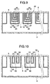
- a sound absorbing panel 40 shown in Fig. 9 has the internal space 10 which is sectioned into a plurality of sections by elongated members 41, 42, 43,..., having different sizes and each having a U-shaped cross section.
- a rear air layer 44 and plural types of slit resonant sound absorbing structures 8, 45, 46, 47, ... are formed.
- elongated members 51, 52, ..., each having a U-shaped cross section are arranged on the lower surface of the sound absorbing member 6 in the internal space 10.
- rear air layers 53, 54,..., and slit resonant sound absorbing structures 8, 55 and 56 are formed.
- the rear air layers and the slit resonant sound absorbing structure in the internal space 10 formed in one sound absorbing panel are not required to have the same structure.
- a plurality of different types may be combined with one another.
- a combination (not shown) of sound absorbing panels 20 and 30 may be combined with each other.
- the structure of the sound absorbing panel is not limited to the illustrated structure.
- a sound absorbing panel 60 shown in Fig. 11 incorporates slit resonant sound absorbing structure 62 formed in the gaps of the elongated members 61 and having a slit width e which is varied in one panel. Since the slit width e is varied, a variety of resonant sound absorbing structures can be realized. The variation of the slit width e is not limited to the variation shown in the drawing. The slit width e may gradually be enlarged or the slit width e may be determined to comply with a certain rule. Similarly, the groove width f of the rear air layer 63 may be varied.
- a sound absorbing panel 65 shown in Fig. 12 may be employed in which the slit width g of the slit resonant sound absorbing structure 66 formed in the internal space 10 or the groove width h of the rear air layer 68 is varied;
- the sound absorbing structure may be constituted by using the wall surface of a building structure. That is, the wall surface of a building structure is substituted for the portion corresponding to the bottom plate 3 shown in Fig. 2 and 5.
- a structure in which the sound absorbing structure according to the present invention is integrally joined to the wall surface of the building structure can be obtained.
- a limited space can effectively be used.
- a light-weight sound absorbing structure which can easily be installed can be obtained.
- the wall surface of a building structure is the surface of a structure on which the sound absorbing structure is attempted to be joined.
- the building structure is exemplified by the wall or the ceiling of a building, the wall surface of a road formed by digging, the wall surface or the ceiling of a tunnel, the lower surface of an elevated bridge and a wall provided along a road or a railway.
- Fig. 13 is an embodiment of an optimum structure of the sound absorbing panel 20 shown in Fig. 5 detected owing to experiments performed by the inventors of the present invention.
- the sound absorbing performance of the sound absorbing panel 20 is graphed as shown in Fig. 14.
- the sound absorbing performance of the rear air layer 22 (Region B) and the sound absorbing performance of the slit resonant sound absorbing structures 8 (Region A) and 23 (Region C) mutually compensate.
- sound absorption free from any leakage can be realized. That is, the maximum value and the minimum value of the sound absorption curve of the resonant sound absorbing structure 8 and those of the rear air layer 22 mutually compensate.
- the sound absorbing performance of the resonant sound absorbing structure 23 is arranged to have a peak at the intersection between curve A and curve B.
- the minimum value of the sound absorbing performance of the slit resonant sound absorbing structure 23 is set at the highest sound absorbing performance.
- the present invention enables a sound absorbing panel which has the following advantages to be obtained.
- the present invention is based on Japanese Patent Applications No. Hei. 11-115488 and No. Hei. 11-305412 which are incorporated herein by reference.
Landscapes
- Engineering & Computer Science (AREA)
- Architecture (AREA)
- Civil Engineering (AREA)
- Structural Engineering (AREA)
- Devices Affording Protection Of Roads Or Walls For Sound Insulation (AREA)
- Building Environments (AREA)
- Soundproofing, Sound Blocking, And Sound Damping (AREA)
- Vehicle Interior And Exterior Ornaments, Soundproofing, And Insulation (AREA)
Abstract
Description
Claims (11)
- A sound absorbing structure comprising:a sound absorbing member;a air layer formed in the rear of said sound absorbing member; anda resonant sound absorbing structure including a slit and formed in the rear of said sound absorbing member.
wherein said sound absorbing member is a surface plate covering said air layer and said resonant sound absorbing structure, and said sound absorbing member is shaped in one of a plate and plane. - The sound absorbing structure according to Claim 1, wherein said sound absorbing member is a surface plate obtained by compression molding metal fibers into a plate-like shape.
- The sound absorbing structure according to claim 1, wherein each of five sides of said sound absorbing member except for the surface plate has a hollow box-shape structure constituted by a plate-like member made of a non-ventilation material.
- The sound absorbing structure according to claim 1, further comprising a plurality of elongated members for constituting said air layer,
wherein said elongated members are disposed below said sound absorbing member at positions apart from one another in a predetermined distance, and said resonant sound absorbing structure is constituted by a gap between the adjacent elongated members. - The sound absorbing structure according to claim 1, wherein said sound absorbing member is supported by a plurality of elongated members disposed in said structure at positions apart from one another in a predetermined distance, each of the elongated members has a concave cross sectional shape which has an internal space in which said rear air layer of said sound absorbing member is formed and which is made of a non-ventilation material, and said resonant sound absorbing structure is formed in a gap defined by the elongated members and the bottom surface of said structure and a gap between adjacent elongated members.
- The sound absorbing structure according to claim 1, wherein at least one type of rear air layer and slit resonant sound absorbing structures are formed in each of the internal spaces of elongated members supporting said sound absorbing member.
- The sound absorbing structure according to claim 1, wherein at least one of a plurality of the widths of said rear air layers and a plurality of the widths of slit openings of said resonant sound absorbing structure is set.
- The sound absorbing structure according to claim 1, wherein a sound absorbing characteristic of said rear air layer and the sound absorbing characteristic of said resonant sound absorbing structure are compensated each other for obtaining the sound absorbing performance in a wide frequency range.
- The sound absorbing structure according to claim 4, wherein said elongated member has a cross section shaped in one of a concave, a U-shape facing side, a U-shape, a V-shape, a semi-circular shape, a triangular shape, a trapezoidal shape and their mixture.
- The sound absorbing structure according to claim 4, wherein said structure is reinforced by said elongated members.
- The sound absorbing structure according to claim 1, wherein said resonant sound absorbing structure is constituted by using the wall surfaces of a building structure.
Applications Claiming Priority (4)
| Application Number | Priority Date | Filing Date | Title |
|---|---|---|---|
| JP11548899 | 1999-04-22 | ||
| JP11548899 | 1999-04-22 | ||
| JP30541299 | 1999-10-27 | ||
| JP30541299A JP3536201B2 (en) | 1999-04-22 | 1999-10-27 | Sound absorbing panel |
Publications (2)
| Publication Number | Publication Date |
|---|---|
| EP1046749A2 true EP1046749A2 (en) | 2000-10-25 |
| EP1046749A3 EP1046749A3 (en) | 2003-07-16 |
Family
ID=26453982
Family Applications (1)
| Application Number | Title | Priority Date | Filing Date |
|---|---|---|---|
| EP00108670A Withdrawn EP1046749A3 (en) | 1999-04-22 | 2000-04-20 | Sound absorbing structure |
Country Status (4)
| Country | Link |
|---|---|
| US (1) | US6568135B1 (en) |
| EP (1) | EP1046749A3 (en) |
| JP (1) | JP3536201B2 (en) |
| KR (1) | KR100399734B1 (en) |
Cited By (6)
| Publication number | Priority date | Publication date | Assignee | Title |
|---|---|---|---|---|
| WO2016038327A1 (en) * | 2014-09-08 | 2016-03-17 | Sonobex Limited | Apparatus and methods |
| US9607600B2 (en) | 2009-02-06 | 2017-03-28 | Sonobex Limited | Attenuators, arrangements of attenuators, acoustic barriers and methods for constructing acoustic barriers |
| EP1742201A4 (en) * | 2004-04-30 | 2017-07-19 | Kabushiki Kaisha Kobe Seiko Sho | Porous sound absorbing structure |
| CN109192190A (en) * | 2018-09-19 | 2019-01-11 | 中国人民解放军国防科技大学 | A thin-layer metamaterial sound-absorbing structure |
| EP4120243A4 (en) * | 2020-03-13 | 2023-08-09 | Pixie Dust Technologies, Inc. | SOUND ABSORBING STRUCTURE AND SOUND ABSORBING WALL |
| EP3108475B1 (en) * | 2014-02-19 | 2025-01-22 | Sonobex Limited | Attenuators, arrangements of attenuators, acoustic barriers and methods for constructing acoustic barriers |
Families Citing this family (38)
| Publication number | Priority date | Publication date | Assignee | Title |
|---|---|---|---|---|
| AUPR773501A0 (en) * | 2001-09-14 | 2001-10-11 | Haven Developments Pty Limited | Noise attenuator |
| JP4050632B2 (en) * | 2003-02-24 | 2008-02-20 | 株式会社神戸製鋼所 | Sound absorbing structure |
| JP2004286808A (en) * | 2003-03-19 | 2004-10-14 | Mitsubishi Heavy Ind Ltd | Sound absorbing structure |
| JP4258288B2 (en) * | 2003-06-25 | 2009-04-30 | トヨタ自動車株式会社 | Sound absorbing structure |
| US20080135332A1 (en) * | 2004-09-03 | 2008-06-12 | Kobe Corporate Research Laboratories In Kobe Steel | Double Wall Structure |
| US20070284185A1 (en) * | 2006-06-07 | 2007-12-13 | Foss Gary C | Damped structural panel and method of making same |
| US8136630B2 (en) * | 2007-06-11 | 2012-03-20 | Bonnie Schnitta | Architectural acoustic device |
| JP5326472B2 (en) * | 2007-10-11 | 2013-10-30 | ヤマハ株式会社 | Sound absorption structure |
| EP2085962A2 (en) * | 2008-02-01 | 2009-08-05 | Yamaha Corporation | Sound absorbing structure and vehicle component having sound absorbing properties |
| US20090223738A1 (en) * | 2008-02-22 | 2009-09-10 | Yamaha Corporation | Sound absorbing structure and vehicle component having sound absorption property |
| JP5359167B2 (en) * | 2008-10-07 | 2013-12-04 | ヤマハ株式会社 | Car body structure and luggage compartment |
| GB0901982D0 (en) | 2009-02-06 | 2009-03-11 | Univ Loughborough | Attenuators, arrangements of attenuators, acoustic barriers and methods for constructing acoustic barriers |
| US20120247867A1 (en) * | 2010-01-08 | 2012-10-04 | Jun Yang | Composite sound-absorbing device with built in resonant cavity |
| KR101051125B1 (en) * | 2010-12-10 | 2011-07-21 | 주식회사 이솜 | Soundproof panel structure with improved sound absorption and structural performance |
| US8474574B1 (en) * | 2012-02-29 | 2013-07-02 | Inoac Corporation | Sound absorbing structure |
| JP2013250501A (en) * | 2012-06-04 | 2013-12-12 | Three M Innovative Properties Co | Sound absorbing board |
| JP6165466B2 (en) * | 2013-02-27 | 2017-07-19 | 株式会社神戸製鋼所 | Soundproof structure |
| FR3010225B1 (en) * | 2013-08-29 | 2016-12-30 | Centre Nat Rech Scient | ABSORBENT ACOUSTIC PANEL |
| US9378721B2 (en) * | 2013-11-06 | 2016-06-28 | Zin Technologies, Inc. | Low frequency acoustic attenuator and process for making same |
| US9493949B2 (en) * | 2014-03-20 | 2016-11-15 | Vanair Design | Panel and panel structure for ventilation and both reactive and dissipative sound dampening |
| US9697817B2 (en) | 2015-05-14 | 2017-07-04 | Zin Technologies, Inc. | Tunable acoustic attenuation |
| US9630575B2 (en) * | 2015-09-30 | 2017-04-25 | GM Global Technology Operations LLC | Panel assembly with noise attenuation system |
| CA3018319C (en) | 2016-03-21 | 2022-03-08 | Hubbell Incorporated | Noise reducing and cooling enclosure |
| DE102016124755B3 (en) * | 2016-12-19 | 2018-02-15 | Liaver Gmbh & Co. Kg | Sound-absorbing component with deletion profiles and sound insulation wall |
| JP6496769B2 (en) * | 2017-04-14 | 2019-04-03 | 日本飛行機株式会社 | Sound absorption panel |
| US10657947B2 (en) * | 2017-08-10 | 2020-05-19 | Zin Technologies, Inc. | Integrated broadband acoustic attenuator |
| CN108396667A (en) * | 2017-11-14 | 2018-08-14 | 同济大学 | Surface configuration and acoustic impedance binary cycle are mutated micropunch ultrabroad band sound absorption structure |
| US11043199B2 (en) * | 2018-04-25 | 2021-06-22 | Toyota Motor Engineering & Manufacturing North America, Inc. | Sparse acoustic absorber |
| US11286859B2 (en) | 2018-08-09 | 2022-03-29 | General Electric Company | Acoustic panel and method for making the same |
| IT201900018695A1 (en) * | 2019-10-14 | 2021-04-14 | Danieli Off Mecc | SOUNDPROOF SMOKE EXHAUST DUCT |
| DE102020201533A1 (en) * | 2020-02-07 | 2021-08-12 | Fraunhofer-Gesellschaft zur Förderung der angewandten Forschung e.V. | DEVICE FOR SOUND CONVERSION WITH AN ACOUSTIC FILTER |
| CN112185327A (en) * | 2020-09-16 | 2021-01-05 | 西安交通大学 | Micro-seam low-frequency sound absorption unit and nested broadband sound absorption structure with same |
| CN112712784B (en) * | 2020-11-30 | 2024-12-31 | 南京华秦光声科技有限责任公司 | A low-frequency broadband flat-plate sound-absorbing structure |
| CN113012673B (en) * | 2021-03-16 | 2024-02-06 | 合肥工业大学 | Sound absorber with adjustable sound absorption frequency band |
| JPWO2023021916A1 (en) * | 2021-08-17 | 2023-02-23 | ||
| CN115662380B (en) * | 2022-10-24 | 2025-11-11 | 国能水务环保有限公司 | Broadband composite sound insulation structure |
| US12203266B2 (en) * | 2022-12-02 | 2025-01-21 | Wiswong Technolgoy Corporation | Construction combination with acoustic absorbing device |
| CN115910017A (en) * | 2022-12-05 | 2023-04-04 | 广东电网有限责任公司 | A dual-frequency anti-linear sound-absorbing metasurface based on multilayer embedded microslit resonators |
Family Cites Families (12)
| Publication number | Priority date | Publication date | Assignee | Title |
|---|---|---|---|---|
| US2161708A (en) * | 1937-07-29 | 1939-06-06 | Paul M Heerwagen | Acoustic surfacing for walls, ceilings, partitions, or the like |
| FR1257985A (en) * | 1960-05-20 | 1961-04-07 | Siemens Ag | Soundproofing device for sound sources - in particular transformers - shielded by means of a material which is not very permeable to sound and provided with insulating compartments |
| US4416349A (en) * | 1981-09-30 | 1983-11-22 | The Boeing Company | Viscoelastically damped reinforced skin structures |
| JP2933322B2 (en) * | 1989-06-30 | 1999-08-09 | 日東紡績株式会社 | Sound absorber |
| JP2779547B2 (en) | 1990-07-17 | 1998-07-23 | 積水ハウス株式会社 | Anchor bolt support device |
| JPH052646A (en) | 1991-06-25 | 1993-01-08 | Sony Corp | Picture processing method |
| JP2547927B2 (en) * | 1992-09-18 | 1996-10-30 | 西日本旅客鉄道株式会社 | Resonance type sound absorbing and sound insulation panel |
| KR950030537U (en) * | 1994-04-19 | 1995-11-20 | Sound absorbing plate installed inside the soundproof wall | |
| JP2815542B2 (en) * | 1994-08-31 | 1998-10-27 | 三菱電機ホーム機器株式会社 | Sound absorption mechanism using porous structure |
| KR100281242B1 (en) * | 1998-06-02 | 2001-02-01 | 허보영 | Noise-proof foamed aluminum panel with resonance structure |
| WO1999063169A2 (en) | 1998-06-02 | 1999-12-09 | Tae Bong Kim | Multi-purpose, aluminum foam-based soundproof panel |
| KR19990024111A (en) * | 1998-12-04 | 1999-03-25 | 조국현 | Panel assembly of soundproof wall |
-
1999
- 1999-10-27 JP JP30541299A patent/JP3536201B2/en not_active Expired - Lifetime
-
2000
- 2000-04-20 EP EP00108670A patent/EP1046749A3/en not_active Withdrawn
- 2000-04-22 KR KR10-2000-0021435A patent/KR100399734B1/en not_active Expired - Fee Related
- 2000-04-24 US US09/556,429 patent/US6568135B1/en not_active Expired - Fee Related
Cited By (7)
| Publication number | Priority date | Publication date | Assignee | Title |
|---|---|---|---|---|
| EP1742201A4 (en) * | 2004-04-30 | 2017-07-19 | Kabushiki Kaisha Kobe Seiko Sho | Porous sound absorbing structure |
| US9607600B2 (en) | 2009-02-06 | 2017-03-28 | Sonobex Limited | Attenuators, arrangements of attenuators, acoustic barriers and methods for constructing acoustic barriers |
| EP3108475B1 (en) * | 2014-02-19 | 2025-01-22 | Sonobex Limited | Attenuators, arrangements of attenuators, acoustic barriers and methods for constructing acoustic barriers |
| WO2016038327A1 (en) * | 2014-09-08 | 2016-03-17 | Sonobex Limited | Apparatus and methods |
| CN109192190A (en) * | 2018-09-19 | 2019-01-11 | 中国人民解放军国防科技大学 | A thin-layer metamaterial sound-absorbing structure |
| CN109192190B (en) * | 2018-09-19 | 2020-05-08 | 中国人民解放军国防科技大学 | Thin-layer metamaterial sound absorption structure |
| EP4120243A4 (en) * | 2020-03-13 | 2023-08-09 | Pixie Dust Technologies, Inc. | SOUND ABSORBING STRUCTURE AND SOUND ABSORBING WALL |
Also Published As
| Publication number | Publication date |
|---|---|
| JP2001003322A (en) | 2001-01-09 |
| US6568135B1 (en) | 2003-05-27 |
| KR20010049281A (en) | 2001-06-15 |
| JP3536201B2 (en) | 2004-06-07 |
| EP1046749A3 (en) | 2003-07-16 |
| KR100399734B1 (en) | 2003-09-29 |
Similar Documents
| Publication | Publication Date | Title |
|---|---|---|
| US6568135B1 (en) | Sound absorbing structure | |
| US20030006090A1 (en) | Broadband noise-suppressing barrier | |
| KR0157277B1 (en) | Sound-absorbing mechanism using porous material | |
| US8696233B2 (en) | Road with sound diffractors | |
| JPH06129029A (en) | Resonance type sound absorbing and insulating panel | |
| IL227116A (en) | Sound protection component | |
| KR100934416B1 (en) | Sound absorption plate for noise prevention | |
| JP2006316467A (en) | Sound insulating double wall structure | |
| JP4585917B2 (en) | Sound absorbing plate and installation method thereof | |
| JPH07145610A (en) | Acoustic panel using porous structure | |
| JP5350183B2 (en) | Metal sound insulation panel with double wall structure | |
| JP2007170166A (en) | Soundproof structure with excellent soundproofing performance | |
| JP3529303B2 (en) | Sound barrier | |
| KR200405950Y1 (en) | Double sided sound absorption panel structure | |
| JP3914395B2 (en) | Noise reduction device, sound insulation wall with the noise reduction device, and method of mounting the same | |
| JP2000303412A (en) | Translucent soundproof plate and soundproof wall using the same | |
| JP3658644B2 (en) | Reduction structure of traffic noise radiated upward | |
| JPS649422B2 (en) | ||
| JP2831562B2 (en) | Noise barrier | |
| KR200287858Y1 (en) | Block type soundproofed wall | |
| KR100992996B1 (en) | Road soundrpoof wall using aluminium foam | |
| KR200317400Y1 (en) | Both-sided Soundproof Panel | |
| KR200184713Y1 (en) | Soundproof wall | |
| KR200208807Y1 (en) | Soundproof wall | |
| KR200401091Y1 (en) | Assembling-type soundproofing panel |
Legal Events
| Date | Code | Title | Description |
|---|---|---|---|
| PUAI | Public reference made under article 153(3) epc to a published international application that has entered the european phase |
Free format text: ORIGINAL CODE: 0009012 |
|
| AK | Designated contracting states |
Kind code of ref document: A2 Designated state(s): AT BE CH CY DE DK ES FI FR GB GR IE IT LI LU MC NL PT SE |
|
| AX | Request for extension of the european patent |
Free format text: AL;LT;LV;MK;RO;SI |
|
| RAP1 | Party data changed (applicant data changed or rights of an application transferred) |
Owner name: ALUMU CORPORATION Owner name: NICHIAS CORPORATION |
|
| RAP1 | Party data changed (applicant data changed or rights of an application transferred) |
Owner name: ALUMU CORPORATION Owner name: NICHIAS CORPORATION |
|
| PUAL | Search report despatched |
Free format text: ORIGINAL CODE: 0009013 |
|
| AK | Designated contracting states |
Designated state(s): AT BE CH CY DE DK ES FI FR GB GR IE IT LI LU MC NL PT SE |
|
| AX | Request for extension of the european patent |
Extension state: AL LT LV MK RO SI |
|
| RIC1 | Information provided on ipc code assigned before grant |
Ipc: 7G 10K 11/172 B Ipc: 7E 01F 8/00 A |
|
| AKX | Designation fees paid | ||
| REG | Reference to a national code |
Ref country code: DE Ref legal event code: 8566 |
|
| STAA | Information on the status of an ep patent application or granted ep patent |
Free format text: STATUS: THE APPLICATION IS DEEMED TO BE WITHDRAWN |
|
| 18D | Application deemed to be withdrawn |
Effective date: 20040117 |