EP1046516A1 - Variable contour grip - Google Patents
Variable contour grip Download PDFInfo
- Publication number
- EP1046516A1 EP1046516A1 EP20000301845 EP00301845A EP1046516A1 EP 1046516 A1 EP1046516 A1 EP 1046516A1 EP 20000301845 EP20000301845 EP 20000301845 EP 00301845 A EP00301845 A EP 00301845A EP 1046516 A1 EP1046516 A1 EP 1046516A1
- Authority
- EP
- European Patent Office
- Prior art keywords
- grip
- instrument
- arrangement according
- writing
- bendable
- Prior art date
- Legal status (The legal status is an assumption and is not a legal conclusion. Google has not performed a legal analysis and makes no representation as to the accuracy of the status listed.)
- Granted
Links
- 238000005452 bending Methods 0.000 claims abstract description 10
- 239000012858 resilient material Substances 0.000 claims abstract description 5
- 230000001846 repelling effect Effects 0.000 claims description 5
- 230000007246 mechanism Effects 0.000 abstract description 8
- 229920001971 elastomer Polymers 0.000 description 4
- 239000005060 rubber Substances 0.000 description 4
- 239000000463 material Substances 0.000 description 3
- 230000008901 benefit Effects 0.000 description 2
- 238000010276 construction Methods 0.000 description 2
- 238000005530 etching Methods 0.000 description 2
- 239000004033 plastic Substances 0.000 description 2
- 229920002379 silicone rubber Polymers 0.000 description 2
- 239000004945 silicone rubber Substances 0.000 description 2
- 101100443236 Drosophila melanogaster Diedel gene Proteins 0.000 description 1
- 210000001015 abdomen Anatomy 0.000 description 1
- 230000008602 contraction Effects 0.000 description 1
- 230000000881 depressing effect Effects 0.000 description 1
- 238000004519 manufacturing process Methods 0.000 description 1
- 239000002184 metal Substances 0.000 description 1
- 230000001681 protective effect Effects 0.000 description 1
- 229920003051 synthetic elastomer Polymers 0.000 description 1
- 239000005061 synthetic rubber Substances 0.000 description 1
Images



Classifications
-
- B—PERFORMING OPERATIONS; TRANSPORTING
- B43—WRITING OR DRAWING IMPLEMENTS; BUREAU ACCESSORIES
- B43K—IMPLEMENTS FOR WRITING OR DRAWING
- B43K23/00—Holders or connectors for writing implements; Means for protecting the writing-points
- B43K23/008—Holders comprising finger grips
-
- B—PERFORMING OPERATIONS; TRANSPORTING
- B43—WRITING OR DRAWING IMPLEMENTS; BUREAU ACCESSORIES
- B43K—IMPLEMENTS FOR WRITING OR DRAWING
- B43K23/00—Holders or connectors for writing implements; Means for protecting the writing-points
- B43K23/004—Holders specially adapted for assisting handicapped or disabled persons to write
-
- B—PERFORMING OPERATIONS; TRANSPORTING
- B43—WRITING OR DRAWING IMPLEMENTS; BUREAU ACCESSORIES
- B43K—IMPLEMENTS FOR WRITING OR DRAWING
- B43K24/00—Mechanisms for selecting, projecting, retracting or locking writing units
- B43K24/02—Mechanisms for selecting, projecting, retracting or locking writing units for locking a single writing unit in only fully projected or retracted positions
- B43K24/023—Mechanisms for selecting, projecting, retracting or locking writing units for locking a single writing unit in only fully projected or retracted positions with a deformable barrel
Definitions
- the present invention relates in general to writing, scribing and lining instruments to be held in the hand such as pens, pencils, markers, styluses, etching tools, scribing tools and the like, and in particular, to a new and useful variable contour grip arrangement for a hand instrument of the type to be held between the fingers of the hand for use.
- U.S. Patent 4,035,089 to Schwartz et al. discloses an expandable grip section for a writing instrument which has a lower casing with two struts connected to a tip.
- a pair of deformable walls supported on a finger grip area around a hollow sleeve encompasses the struts.
- An expander element is between the sleeve and deformable walls. When the sleeve is rotated, the expander element causes the walls to deform outwardly.
- the struts themselves are not deformable.
- U.S. Patent 1,868,441 to Colfelt discloses an adjustable grip section for a writing instrument.
- the grip fits over the writing instrument and has a deformable bulbous body enclosing an air space around the writing instrument.
- the size of the bulbous body may be adjusted by rotating two threaded members.
- U.S. Patent 1,598,873 to Peterson discloses a slidable finger grip for a writing instrument which is also used as a cap and a clip.
- the finger grip is cylindrical with convex sides.
- the grip is made of resilient material, such as rubber, but does not substantially change shape during use.
- U.S. Patent 5,143,463 to Pozil et al. discloses a pear-shaped cylinder writing grip for surrounding a writing instrument body.
- the grip is made of pliable rubber and shaped to improve the feel of the writing instrument when used over a long period.
- the writing grip is not integrated with the writing instrument.
- SIR Statutory Invention Registration
- H 1050 to Petrillo discloses a resilient grip portion for a writing instrument body adjacent the writing tip.
- the grip portion is formed by a tubular segment having axial slots.
- the tubular segment may be integral with the writing instrument body, or a separate piece which is fit over the writing instrument body.
- the tubular segment is covered by an elongated sleeve.
- a writing instrument with a deformable end for enclosing the writing tip is taught by U.S. Patent 5,725,323 to Wittek.
- the writing tip is propelled outwardly through an expanding end of the barrel adjacent the grip section by depressing the back end of the cartridge the writing tip is part of.
- the internal construction of the writing instrument causes the cartridge and writing tip to retract back into the barrel.
- the grip portion of the writing instrument does not deform.
- U.S. Patent 4,595,307 to Heyden discloses a bulbous writing tip cover.
- the cover is positioned over the writing tip adjacent the grip and is intended solely as a protective cover for the writing tip.
- the present invention comprises a hand instrument which may be a writing instrument, such as a pen, with a retractable writing tip and having a grip section adjacent the writing tip end of the pen.
- the invention is not limited to writing instruments, however but may be used for any hand instrument of the type which is held between the fingers of the hand of a user during use. Examples include computer styluses, scribing and etching tools, cutting blades and chisels, markers, brushes, surgical instruments and a wide variety of other hand instruments which can benefit by having a grip that can take on an expanded ergonomic position for use, but which also has a contracted position for carrying or storage.
- the grip when the writing tip is extended or propelled to a writing position, the grip may also deform and expand to the shape or position which is more easily held by a person, namely a preferably triangular ergonomic position.
- the grip substantially conforms to the outer contour of the writing instrument when the writing tip is retracted.
- three circumferentially spaced flexible beams inside the grip section are engaged by a cam mechanism and bend outwardly at the same time the writing tip is propelled to a writing position.
- a deformable grip material such as silicone rubber, surrounding the beams expands outwardly when the beams bend, providing an expanded grip position for writing.
- the beams which may be made of plastic or metal, resiliently return to their original shape as the writing tip is retracted (repelled). Similarly, the deformable grip material resiliently reverts to the original shape of the pen around the beams.
- an object of the present invention is to provide a variable contour grip arrangement for a hand instrument of the type to be held between the fingers of the hand for use, comprising: an instrument body having an active end and an opposite end; a resilient material forming a grip around the body near the active end; radial expansion means in the body and under the grip for expanding radially for expanding the grip into an expanded ergonomic position and for contacting radially for contracting the grip into a contracted storage position; and movable actuation means engaged with the radial expansion means for moving the radial expansion means between the expanded and the contracted positions.
- a further object of the present invention is to provide such an arrangement where the instrument is a writing instrument with propelling means for propelling and repelling a writing tip from and into the active end of the body, the movable actuation means either acting with or separately of the propelling means so that the writing tip can either be propelled with expansion of the grip or propelled separately of any movement of the grip.
- a further object of the present invention is to provide the expansion means in the form of at least three bendable members in the instrument body which are circumferentially spaced inside the grip and which are bent outwardly by the movable actuation means.
- a still further object of the present invention is to provide a variable contour grip arrangement which is simple in design, rugged in construction, and economical to manufacture.
- Fig. 1 the invention embodied in Fig. 1 comprises a hand instrument 10 with variable grip arrangement 12.
- the instrument has an instrument body of the type to be held between the fingers of the hand for use as shown in Fig. 5.
- the body has an active end 14 and an opposite end 16.
- a resilient material such as silicone rubber, forms a grip or sleeve 18 around the body near the active end 14.
- Radial expansion means 20 in the body 10 and under the grip 18 expand radially for expanding the grip 18 into an expanded ergonomic position shown in Fig. 2, and for contacting radially for contracting the grip into a contracted storage position shown in Fig. 1. Contraction of the grip occurs automatically due to the resilient nature of the grip material which may be SANEPRENE rubber, a trademark for a synthetic rubber.
- the radial expansion means are moved by movable actuation means 22 engaged with the radial expansion means for moving the radial expansion means between the expanded and the contracted positions.
- the instrument is a writing instrument with propelling means 24 for propelling and repelling a writing tip 26 from and into the active end 14 of the body 10.
- the movable actuation means may act with or without the propelling means so that the writing tip is propelled with expansion of the grip or the propelling means and the movable actuation means may acting independently so that the writing tip is propelled independently of expansion of the grip.
- the actions occur together, in the embodiment of Fig. 11, they are independent.
- the expansion means 28 in Fig. 1 comprises at least three bendable members 28 in the instrument body which are circumferentially spaced inside the grip 18 and which are bent outwardly by the movable actuation means. Only two of the beams are visible in Figs. 1 and 2. Three beams are preferred because they create a triangular expanded position, but more beams can be used for a more cylindrical ergonomic grip.
- the body 10 includes an upper body portion 30 which carries the opposite end 16, and a lower body portion 32 which carries the grip 18 and the active end 14.
- the actuation means comprises a fixed cam 34 on body portion 30 and a sliding cam 36 on body portion 32 engaged with the fixed cam 34 for movement with relative rotation of the body portions illustrated by arrow A for bending the bendable members or beams 28.
- the actuation means comprise thread means between the body portions 30, 32 for movement with rotation of a band or ring 38 for bending the bendable members which in the embodiments of Figs. 7-11, are free ended cantilever beams 48.
- the free end 49 of the cantilever beams 48 ride on inclined bending surface 50 in the body for bending each beam radially outwardly when each beam moves axially along the inclined surface due to the action of the cam or thread means which moves the upper end of the beams axially downwardly in the figures as is apparent by comparing Fig. 7 (the contracted position) with Fig. 10 (the expanded position).
- the bendable members 28 each have one fixed end 29 and one axially movable end 31, the axially movable ends being moved axially and together by the actuation means.
- Fig. 6 schematically illustrates the action of the cams 34 and 36 which form one embodiment of the actuation means.
- each of the three bendable beams 48 will slide along the radially outwardly extending inclined surface 50, causing the beams to each bend outwardly, as shown for example in Fig. 10.
- Fig. 9 shows the outwardly bent positions for the ends 49 of the beams and how this causes the resilient grip 18 to take on a triangular, ergonomic shape shown also in Fig. 5.
- Fig. 8 shows the contracted position for the various parts of the invention which produces the smooth outer contour illustrated in Fig. 7 which is more convenient for storage in the pocket or in a storage receptacle, than the expanded ergonomic position, which is useful during use of the pen as shown in Fig. 5.
- Fig. 7 also shows details of the propelling mechanism 24 which is of conventional design and includes, for example, a helical groove on the outer surface of a pen refill containing structure 60, in which cam followers 62 on the inside surface of fixed cam 34, ride.
- cam followers 62 rotate in the helical groove and cause the writing tip and the entire ink cartridge to move axially downwardly thus projecting the tip 26 beyond the lower active end 14 of the instrument body.
- a similar mechanism is provided in Figs. 1, 2 and 10 so that with relative rotation of the body portions, both the writing tip is extended (propelled) and the grip is expanded.
- ring 38 has inner male threads 66 which engage outer female threads 68 of a threaded projection of a portion 69 which carries the upper ends of the three bendable beams 48 and three non bendable beams 47 which ride in rectangular grooves 43.
- Beams 48 and beams 47 alternate and are spaced circumferentially around the member 69 so that the axial movement of member 69 is aligned properly and axially with a member 41 which carries the grooves 43 and the inclined surfaces 50 that also alternate and are spaced circumferentially around member 41.
- Upper body portion 30 can be rotated with respect to lower body portion 41 and includes on its inner surface at 80, a known mechanism for propelling and repelling the ink cartridge receiving structure 60. Because of the placement of ring 38 at the junction between the upper and lower body portions, one can hold both the ring 38 and the upper body portion 30 and rotate them together to extend the writing tip 26 at the same time that the grip 18 is expanded. Alternatively, the body 30 can be rotated independently for extending the writing tip 26 without expanding the grip 18 and further alternatively, the grip can be expanded without extending the writing tip.
Landscapes
- Mechanical Pencils And Projecting And Retracting Systems Therefor, And Multi-System Writing Instruments (AREA)
- Pens And Brushes (AREA)
- Arrangement Or Mounting Of Control Devices For Change-Speed Gearing (AREA)
- Pharmaceuticals Containing Other Organic And Inorganic Compounds (AREA)
- Lock And Its Accessories (AREA)
- Instruments For Viewing The Inside Of Hollow Bodies (AREA)
- Brushes (AREA)
- Passenger Equipment (AREA)
Abstract
Description
- The present invention relates in general to writing, scribing and lining instruments to be held in the hand such as pens, pencils, markers, styluses, etching tools, scribing tools and the like, and in particular, to a new and useful variable contour grip arrangement for a hand instrument of the type to be held between the fingers of the hand for use.
- U.S. Patent 4,035,089 to Schwartz et al. discloses an expandable grip section for a writing instrument which has a lower casing with two struts connected to a tip. A pair of deformable walls supported on a finger grip area around a hollow sleeve encompasses the struts. An expander element is between the sleeve and deformable walls. When the sleeve is rotated, the expander element causes the walls to deform outwardly. The struts themselves are not deformable.
- Other patents teach shaped attachments which fit around the body of a writing instrument, such as the anti-nervous grip of U.S. Patent 266,442 to Diedel. The grip is a triangular column which can expand to fit around different sized writing instruments. The flat panels of the triangular column are deformable to provide an improved grip section.
- U.S. Patent 1,868,441 to Colfelt discloses an adjustable grip section for a writing instrument. The grip fits over the writing instrument and has a deformable bulbous body enclosing an air space around the writing instrument. The size of the bulbous body may be adjusted by rotating two threaded members.
- U.S. Patent 1,598,873 to Peterson discloses a slidable finger grip for a writing instrument which is also used as a cap and a clip. The finger grip is cylindrical with convex sides. The grip is made of resilient material, such as rubber, but does not substantially change shape during use.
- U.S. Patent 5,143,463 to Pozil et al. discloses a pear-shaped cylinder writing grip for surrounding a writing instrument body. The grip is made of pliable rubber and shaped to improve the feel of the writing instrument when used over a long period. The writing grip is not integrated with the writing instrument.
- Statutory Invention Registration (SIR), H 1050 to Petrillo discloses a resilient grip portion for a writing instrument body adjacent the writing tip. The grip portion is formed by a tubular segment having axial slots. The tubular segment may be integral with the writing instrument body, or a separate piece which is fit over the writing instrument body. The tubular segment is covered by an elongated sleeve.
- A writing instrument with a deformable end for enclosing the writing tip is taught by U.S. Patent 5,725,323 to Wittek. The writing tip is propelled outwardly through an expanding end of the barrel adjacent the grip section by depressing the back end of the cartridge the writing tip is part of. When the writing instrument is not used for several minutes, the internal construction of the writing instrument causes the cartridge and writing tip to retract back into the barrel. The grip portion of the writing instrument does not deform.
- U.S. Patent 4,595,307 to Heyden discloses a bulbous writing tip cover. The cover is positioned over the writing tip adjacent the grip and is intended solely as a protective cover for the writing tip.
- The present invention comprises a hand instrument which may be a writing instrument, such as a pen, with a retractable writing tip and having a grip section adjacent the writing tip end of the pen. The invention is not limited to writing instruments, however but may be used for any hand instrument of the type which is held between the fingers of the hand of a user during use. Examples include computer styluses, scribing and etching tools, cutting blades and chisels, markers, brushes, surgical instruments and a wide variety of other hand instruments which can benefit by having a grip that can take on an expanded ergonomic position for use, but which also has a contracted position for carrying or storage.
- In the case of a pen with retractable tip, when the writing tip is extended or propelled to a writing position, the grip may also deform and expand to the shape or position which is more easily held by a person, namely a preferably triangular ergonomic position. The grip substantially conforms to the outer contour of the writing instrument when the writing tip is retracted.
- In one embodiment of the invention, three circumferentially spaced flexible beams inside the grip section are engaged by a cam mechanism and bend outwardly at the same time the writing tip is propelled to a writing position. A deformable grip material, such as silicone rubber, surrounding the beams expands outwardly when the beams bend, providing an expanded grip position for writing.
- The beams, which may be made of plastic or metal, resiliently return to their original shape as the writing tip is retracted (repelled). Similarly, the deformable grip material resiliently reverts to the original shape of the pen around the beams.
- Other embodiments of the invention use thread mechanisms to selectively and separately activate the writing tip and grip contour.
- Accordingly, an object of the present invention is to provide a variable contour grip arrangement for a hand instrument of the type to be held between the fingers of the hand for use, comprising: an instrument body having an active end and an opposite end; a resilient material forming a grip around the body near the active end; radial expansion means in the body and under the grip for expanding radially for expanding the grip into an expanded ergonomic position and for contacting radially for contracting the grip into a contracted storage position; and movable actuation means engaged with the radial expansion means for moving the radial expansion means between the expanded and the contracted positions.
- A further object of the present invention is to provide such an arrangement where the instrument is a writing instrument with propelling means for propelling and repelling a writing tip from and into the active end of the body, the movable actuation means either acting with or separately of the propelling means so that the writing tip can either be propelled with expansion of the grip or propelled separately of any movement of the grip.
- A further object of the present invention is to provide the expansion means in the form of at least three bendable members in the instrument body which are circumferentially spaced inside the grip and which are bent outwardly by the movable actuation means.
- A still further object of the present invention is to provide a variable contour grip arrangement which is simple in design, rugged in construction, and economical to manufacture.
- The various features of novelty which characterize the invention are pointed out with particularity in the claims annexed to and forming a part of this disclosure. For a better understanding of the invention, its operating advantages and specific objects attained by its uses, reference is made to the accompanying drawings and descriptive matter in which a preferred embodiment of the invention is illustrated.
- In the drawings:
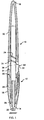
- Fig. 1 is an axial sectional view of a hand instrument with variable contour grip arrangement of the present invention;
- Fig. 2 is a view similar to Fig. 1 of the instrument with its grip in an expanded ergonomic position;
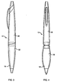
- Fig. 3 is a side elevational view of an instrument of the invention with its writing tip repelled (retracted) and its grip contracted into a storage position;
- Fig. 4 is a view similar to Fig. 3 with the writing tip propelled (extended) and the grip in its expanded ergonomic position for use;
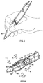
- Fig. 5 is a perspective view of the instrument of Fig. 4 as it is being held by the hand of a user for an ergonomic grip;
- Fig. 6 is an explanatory illustration of one embodiment for the mechanism for varying the contour of the grip of the invention;
- Fig. 7 is an axial sectional view of another embodiment of the hand instrument with variable contour grip arrangement of the present invention;
- Fig. 8 is a radial sectional view taken along line 8-8 of Fig. 7. showing the grip contour mechanism in its contacted storage position;
- Fig. 9, is a view similar to Fig. 8 but in the expanded position for the grip;
- Fig. 10 is a view similar to Fig. 7 showing another embodiment of the invention in a grip expanded position; and
- Fig. 11 is a view similar to Fig. 10 showing a still further embodiment of the invention in a grip contracted position.
-
- Referring to the drawings in particular, the invention embodied in Fig. 1 comprises a
hand instrument 10 withvariable grip arrangement 12. The instrument has an instrument body of the type to be held between the fingers of the hand for use as shown in Fig. 5. The body has anactive end 14 and anopposite end 16. A resilient material, such as silicone rubber, forms a grip or sleeve 18 around the body near theactive end 14. - Radial expansion means 20 in the
body 10 and under thegrip 18 expand radially for expanding thegrip 18 into an expanded ergonomic position shown in Fig. 2, and for contacting radially for contracting the grip into a contracted storage position shown in Fig. 1. Contraction of the grip occurs automatically due to the resilient nature of the grip material which may be SANEPRENE rubber, a trademark for a synthetic rubber. - The radial expansion means are moved by movable actuation means 22 engaged with the radial expansion means for moving the radial expansion means between the expanded and the contracted positions.
- In the figures the instrument is a writing instrument with propelling
means 24 for propelling and repelling awriting tip 26 from and into theactive end 14 of thebody 10. The movable actuation means may act with or without the propelling means so that the writing tip is propelled with expansion of the grip or the propelling means and the movable actuation means may acting independently so that the writing tip is propelled independently of expansion of the grip. In the embodiment of Figs. 1-10, the actions occur together, in the embodiment of Fig. 11, they are independent. - The expansion means 28 in Fig. 1, comprises at least three
bendable members 28 in the instrument body which are circumferentially spaced inside thegrip 18 and which are bent outwardly by the movable actuation means. Only two of the beams are visible in Figs. 1 and 2. Three beams are preferred because they create a triangular expanded position, but more beams can be used for a more cylindrical ergonomic grip. - The
body 10 includes anupper body portion 30 which carries theopposite end 16, and alower body portion 32 which carries thegrip 18 and theactive end 14. The actuation means comprises a fixedcam 34 onbody portion 30 and a slidingcam 36 onbody portion 32 engaged with the fixedcam 34 for movement with relative rotation of the body portions illustrated by arrow A for bending the bendable members or beams 28. - In the embodiment of Fig. 11, where the same reference numerals are used to designated the same or functionally similar parts, the actuation means comprise thread means between the
body portions ring 38 for bending the bendable members which in the embodiments of Figs. 7-11, are free ended cantilever beams 48. - The
free end 49 of the cantilever beams 48 ride on inclined bendingsurface 50 in the body for bending each beam radially outwardly when each beam moves axially along the inclined surface due to the action of the cam or thread means which moves the upper end of the beams axially downwardly in the figures as is apparent by comparing Fig. 7 (the contracted position) with Fig. 10 (the expanded position). - In Figs. 1, 2 and 6 the
bendable members 28 each have one fixedend 29 and one axiallymovable end 31, the axially movable ends being moved axially and together by the actuation means. - Fig. 6 schematically illustrates the action of the
cams - This expands the resilient outer sleeve or grip 18 (Fig. 2), causing it to take on a rounded triangular cross action shown in Fig. 9.
- As shown in Figs. 7-9, the free ends 49 of the cantilever beams 48, when sliding
cam 36 is moved downwardly by the fixedcam 34 and the relative rotation between the upper and lower body portions, each of the threebendable beams 48 will slide along the radially outwardly extendinginclined surface 50, causing the beams to each bend outwardly, as shown for example in Fig. 10. - Fig. 9 shows the outwardly bent positions for the
ends 49 of the beams and how this causes theresilient grip 18 to take on a triangular, ergonomic shape shown also in Fig. 5. - Since the outer surfaces of the beams must slide, and further because the inner surface of the grip or
sleeve 18 is a high friction surface, it has been found useful to provide plastic slide beams 52 over thebendable beams 48 which also bend outwardly with thebeams 48 and which directly contact the inner surface ofsleeve 18. Slide beams 52 do not, however, slide with respect to the rubber grip, but beams 48 slide slightly against inner surfaces ofbeams 52. - Fig. 8 shows the contracted position for the various parts of the invention which produces the smooth outer contour illustrated in Fig. 7 which is more convenient for storage in the pocket or in a storage receptacle, than the expanded ergonomic position, which is useful during use of the pen as shown in Fig. 5.
- Fig. 7 also shows details of the propelling
mechanism 24 which is of conventional design and includes, for example, a helical groove on the outer surface of a penrefill containing structure 60, in whichcam followers 62 on the inside surface of fixedcam 34, ride. When theupper instrument body 30 rotates with respect to the lower,cam followers 62 rotate in the helical groove and cause the writing tip and the entire ink cartridge to move axially downwardly thus projecting thetip 26 beyond the loweractive end 14 of the instrument body. A similar mechanism is provided in Figs. 1, 2 and 10 so that with relative rotation of the body portions, both the writing tip is extended (propelled) and the grip is expanded. - In the embodiment of Fig. 11,
ring 38 has innermale threads 66 which engage outerfemale threads 68 of a threaded projection of aportion 69 which carries the upper ends of the threebendable beams 48 and three nonbendable beams 47 which ride inrectangular grooves 43.Beams 48 andbeams 47 alternate and are spaced circumferentially around themember 69 so that the axial movement ofmember 69 is aligned properly and axially with amember 41 which carries thegrooves 43 and theinclined surfaces 50 that also alternate and are spaced circumferentially aroundmember 41. -
Upper body portion 30 can be rotated with respect tolower body portion 41 and includes on its inner surface at 80, a known mechanism for propelling and repelling the inkcartridge receiving structure 60. Because of the placement ofring 38 at the junction between the upper and lower body portions, one can hold both thering 38 and theupper body portion 30 and rotate them together to extend thewriting tip 26 at the same time that thegrip 18 is expanded. Alternatively, thebody 30 can be rotated independently for extending thewriting tip 26 without expanding thegrip 18 and further alternatively, the grip can be expanded without extending the writing tip. - While specific embodiments of the invention have been shown and described in detail to illustrate the application of the principles of the invention, it will be understood that the invention may be embodied otherwise without departing from such principles.
Claims (10)
- A hand instrument with variable grip arrangement comprising:an instrument body of the type to be held between the fingers of the hand for use, the body having an active end and an opposite end;a resilient material forming a grip around the body near the active end;radial expansion means in the body and under the grip for expanding radially, for expanding the grip into an expanded ergonomic position and for contacting radially for contracting the grip into a contracted storage position; andmovable actuation means engaged with the radial expansion means for moving the radial expansion means between the expanded and the contracted positions.
- An arrangement according to Claim 1 wherein the instrument is a writing instrument with propelling means for propelling and repelling a writing tip from and into the active end of the body, the movable actuation means acting with the propelling means so that the writing tip is propelled with expansion of the grip.
- An arrangement according to Claim 1 wherein the instrument is a writing instrument with propelling means for propelling and repelling a writing tip from and into the active end of the body, the movable actuation means acting independently of the propelling means so that the writing tip is propelled independently of expansion of the grip.
- An arrangement according to Claim 1 wherein the expansion means comprises at least three bendable members in the instrument body which are circumferentially spaced inside the grip and which are bent outwardly by the movable actuation means.
- An arrangement according to Claim 4 wherein the body includes an upper body portion which carries the opposite end, and a lower body portion which carries the grip and the active end, the actuation means comprising a fixed cam on one of the body portions and a sliding cam on the other of the body portions engaged with the fixed cam and for movement with relative rotation of the body portions for bending the bendable members.
- An arrangement according to Claim 4 wherein the body includes an upper body portion which carries the opposite end, and a lower body portion which carries the grip and the active end, the actuation means comprising thread means between the body portions for movement with rotation of the actuation means for bending the bendable members.
- An arrangement according to Claim 6 wherein the thread means includes a rotatable ring around the instrument body which is rotatable for bending the bendable members.
- An arrangement according to Claim 4 wherein the bendable members each comprise an bendable cantilever beam and an inclined bending surface in the body engaged with a free end of each beam for bending each beam radially outwardly when each beam moves axially along the inclined surface.
- An arrangement according to Claim 8 including bendable slide beams between each bendable member and the grip.
- An arrangement according to Claim 4 wherein the bendable members each have one fixed end and one axially movable end, the axially movable ends being moved axially and together by the actuation means.
Applications Claiming Priority (2)
| Application Number | Priority Date | Filing Date | Title |
|---|---|---|---|
| US09/296,730 US6146038A (en) | 1999-04-22 | 1999-04-22 | Variable contour grip |
| US296730 | 1999-04-22 |
Publications (2)
| Publication Number | Publication Date |
|---|---|
| EP1046516A1 true EP1046516A1 (en) | 2000-10-25 |
| EP1046516B1 EP1046516B1 (en) | 2004-06-09 |
Family
ID=23143307
Family Applications (1)
| Application Number | Title | Priority Date | Filing Date |
|---|---|---|---|
| EP00301845A Expired - Lifetime EP1046516B1 (en) | 1999-04-22 | 2000-03-07 | Variable contour grip |
Country Status (10)
| Country | Link |
|---|---|
| US (1) | US6146038A (en) |
| EP (1) | EP1046516B1 (en) |
| JP (1) | JP2000313193A (en) |
| KR (1) | KR100367723B1 (en) |
| AT (1) | ATE268694T1 (en) |
| CA (1) | CA2299839A1 (en) |
| DE (1) | DE60011338T2 (en) |
| ES (1) | ES2221828T3 (en) |
| SG (1) | SG85695A1 (en) |
| TW (1) | TW490400B (en) |
Cited By (5)
| Publication number | Priority date | Publication date | Assignee | Title |
|---|---|---|---|---|
| WO2003070487A1 (en) * | 2002-02-20 | 2003-08-28 | Luc Marcel Lafond | Retractable writing instrument |
| EP1585016A1 (en) * | 2004-04-08 | 2005-10-12 | Siemens Aktiengesellschaft | Convertible input element for an electronic device |
| WO2006065260A1 (en) * | 2004-12-13 | 2006-06-22 | Jakks Pacific, Inc | Writing instrument with inflatable bladders |
| EP1557290A4 (en) * | 2002-10-23 | 2007-12-26 | Pentel Kk | VARIABLE HANDLE STRUCTURE |
| CN113510921A (en) * | 2021-04-01 | 2021-10-19 | 魏成浩 | Production system and production process of high-pressure hydraulic rubber pipe |
Families Citing this family (52)
| Publication number | Priority date | Publication date | Assignee | Title |
|---|---|---|---|---|
| US20030123917A1 (en) * | 2000-01-15 | 2003-07-03 | Boyd Willat | Tubular deformable sleeve and related apparatus |
| AU2002219812A1 (en) * | 2000-11-14 | 2002-05-27 | Avery Dennison Corporation | Multi-media writing instruments and methods for their use |
| US6648535B2 (en) * | 2001-02-27 | 2003-11-18 | Daniel A. Ferrara, Jr. | Cushioning element |
| DE20108903U1 (en) * | 2001-05-28 | 2001-08-02 | Shueh, Ho-Yuan, Hsintien, Taipeh | Formable housing of pressure pens |
| USD472579S1 (en) | 2002-06-28 | 2003-04-01 | Shu-Hui Kuo Chiang | Ball-point pen |
| USD477025S1 (en) | 2002-08-05 | 2003-07-08 | Berol Corporation | Writing instrument |
| USD481069S1 (en) | 2002-09-12 | 2003-10-21 | Sanford L.P. | Grip for a writing instrument |
| US20040126556A1 (en) * | 2002-12-27 | 2004-07-01 | Nowak Michael T. | Grip element |
| USD486182S1 (en) | 2003-04-14 | 2004-02-03 | Pentel Of America, Ltd. | Grip for a writing instrument |
| USD486857S1 (en) | 2003-04-14 | 2004-02-17 | Pentel Of America, Ltd. | Writing instrument |
| USD492723S1 (en) | 2003-04-16 | 2004-07-06 | Shu-Hui Kuo Chiang | Ball-point pen |
| US7046236B2 (en) * | 2003-05-22 | 2006-05-16 | International Business Machines Corporation | Stylus for portable computing and processing systems |
| US6964103B2 (en) * | 2003-09-08 | 2005-11-15 | Acme United Corporation | Retractable point compass |
| US6921223B2 (en) * | 2003-09-15 | 2005-07-26 | Sanford, L.P. | Combo pen |
| USD493484S1 (en) | 2003-09-26 | 2004-07-27 | Elmer's Products, Inc. | Writing instrument |
| USD499447S1 (en) | 2003-10-06 | 2004-12-07 | Chiang Shu Hui-Kuo | Combination stylus and pen |
| USD502218S1 (en) * | 2003-12-31 | 2005-02-22 | Quadrinvest S.P.A. | Pen |
| USD501031S1 (en) * | 2003-12-31 | 2005-01-18 | Quadrinvest S.P.A. | Pen |
| USD501508S1 (en) * | 2003-12-31 | 2005-02-01 | Quadrinvest S.P.A. | Pen |
| USD500339S1 (en) | 2004-04-02 | 2004-12-28 | Kun-Tsai Yeh | Pen |
| USD512099S1 (en) * | 2004-04-12 | 2005-11-29 | Pentel Kabushiki Kaisha | Mechanical pencil |
| USD512098S1 (en) * | 2004-06-30 | 2005-11-29 | Ningbo Beifa Group Co., Ltd. | Mechanical pencil |
| USD506503S1 (en) * | 2004-06-30 | 2005-06-21 | Ningbo Beifa Group Co., Ltd. | Mechanical pencil |
| FR2874855B1 (en) * | 2004-09-08 | 2006-12-08 | Bic Sa Soc | WRITING INSTRUMENT |
| JP4555657B2 (en) * | 2004-10-15 | 2010-10-06 | ミクロ株式会社 | Writing instrument |
| US7797782B2 (en) * | 2005-06-21 | 2010-09-21 | Goody Products, Inc. | Handle having a ribbed gel grip |
| USD551712S1 (en) * | 2005-11-15 | 2007-09-25 | Jakks Pacific, Inc. | Mouse touch roller pencil |
| US20080112748A1 (en) * | 2006-11-09 | 2008-05-15 | Carl Cetera | Slidable spring-biased grip for a handheld writing implement |
| FR2909005B1 (en) * | 2006-11-23 | 2009-02-27 | Babolat Vs Sa | INSERT FOR RAQUETTE SLEEVE, HAND AND RAQUETTE CORRESPONDING. |
| USD591345S1 (en) * | 2007-10-17 | 2009-04-28 | Beifa Group Co., Ltd. | Pen |
| JP5110691B2 (en) * | 2007-11-01 | 2012-12-26 | 三菱鉛筆株式会社 | Writing instrument |
| US7621023B2 (en) * | 2007-12-04 | 2009-11-24 | Marshalltown Company | Adjustable tool handle |
| US8745825B2 (en) * | 2008-07-10 | 2014-06-10 | Scalpal Llc | Gripping sleeve device for precision instruments |
| IL192739A (en) | 2008-07-10 | 2015-07-30 | Scalpal Llc | Handle for surgical and dental tools |
| US8480323B2 (en) | 2010-04-30 | 2013-07-09 | A.T.X. International, Inc. | Expandable writing instrument |
| KR101055277B1 (en) * | 2010-12-31 | 2011-08-09 | 이정섭 | Climbing Stick Handle |
| US20140099151A1 (en) * | 2012-10-06 | 2014-04-10 | Shazam Abdul | Marking Enhancement Device |
| US20150153851A1 (en) * | 2013-03-08 | 2015-06-04 | Dell Products, Lp | Flexible Pen in Narrow Garage |
| US20140253519A1 (en) * | 2013-03-08 | 2014-09-11 | Michael David | Expandable diameter stylus |
| US9304610B2 (en) * | 2013-05-20 | 2016-04-05 | Lenovo (Singapore) Pte. Ltd. | Expanding pen for information handling device |
| JP2015100987A (en) * | 2013-11-25 | 2015-06-04 | ミクロ株式会社 | Rotary writing instrument |
| US10073544B2 (en) | 2015-10-14 | 2018-09-11 | Microsoft Technology Licensing, Llc | Stylus with adjustable grip diameter |
| DE102015014923B4 (en) * | 2015-11-17 | 2019-06-19 | Gerhard Mahlich | Universally applicable in everyday life Greifstifthülse, handling device called, especially a writing instrument for hand and foot, individually or in a modular system |
| US10185409B2 (en) | 2016-03-15 | 2019-01-22 | Microsoft Technology Licensing, Llc | Stylus with an adjustable dimension |
| US10005177B2 (en) * | 2016-06-06 | 2018-06-26 | GM Global Technology Operations LLC | Adjustable grip size for curved or straight grip |
| CN107443957A (en) * | 2017-09-11 | 2017-12-08 | 宁波文魁智能设备制造有限公司 | A kind of penholder component and pen for grip position correction |
| CN107571663B (en) * | 2017-10-24 | 2024-06-18 | 宋恒曦 | Adjustable pen holder |
| US10780569B2 (en) * | 2018-03-05 | 2020-09-22 | Acme United Corporation | Knife having adjustable handle |
| US10406849B1 (en) | 2019-02-07 | 2019-09-10 | Khaled A. M. A. A. Al-Khulaifi | Training pen for writing |
| CN112274243A (en) * | 2020-10-29 | 2021-01-29 | 华中科技大学同济医学院附属协和医院 | A rechargeable pressure-sensitive temperature-controlled microsurgical electrocoagulation pen with replaceable tip electrodes |
| CN113155352B (en) * | 2021-04-02 | 2022-10-21 | 普力斯特测控技术(天长)有限公司 | Exquisite differential pressure transmitter with monocrystalline silicon chip |
| KR102823882B1 (en) * | 2023-07-04 | 2025-06-24 | 국립공주대학교 산학협력단 | A golf putter having a variable cross-sectional shape grip |
Citations (12)
| Publication number | Priority date | Publication date | Assignee | Title |
|---|---|---|---|---|
| US1598873A (en) | 1924-01-12 | 1926-09-07 | Peterson William | Finger piece for writing instruments |
| US1868441A (en) | 1931-08-14 | 1932-07-19 | Wilma M Colfelt | Writing pad for writing instruments |
| US2576751A (en) * | 1945-12-29 | 1951-11-27 | Paul H Dortmund | Expansible tool handle |
| US4035089A (en) | 1973-03-14 | 1977-07-12 | Schwartz Allan E | Mechanism for varying the finger grip area of a writing implement |
| DE3214706A1 (en) * | 1981-05-21 | 1982-12-09 | Hans 6200 Wiesbaden Orth | Hand-held writing instrument, especially a ballpoint pen |
| US4475834A (en) * | 1982-04-02 | 1984-10-09 | Bean Donald F | Writing instrument projectable by fluid pressure |
| US4595307A (en) | 1984-11-01 | 1986-06-17 | Heyden Eugene L | Retractable implement closure |
| EP0353379A2 (en) * | 1988-07-30 | 1990-02-07 | Ancos Co., Ltd. | Mechanical pencil having an automatic lead extending mechanism |
| US5143463A (en) | 1990-12-24 | 1992-09-01 | Pozil Richard L | Writing aid |
| US5263275A (en) * | 1992-04-10 | 1993-11-23 | Berkley, Inc. | Variable circumference rod handle |
| DE4405684C1 (en) * | 1994-02-22 | 1995-07-06 | Dozsa Farkas Andras | Writing implement with variable dia. handgrip |
| US5725323A (en) | 1989-02-15 | 1998-03-10 | Intergraph Office Innovation N.V. | Writing appliance that closes automatically after a given time interval |
Family Cites Families (2)
| Publication number | Priority date | Publication date | Assignee | Title |
|---|---|---|---|---|
| US3070370A (en) * | 1959-12-29 | 1962-12-25 | James V Steiner | Variable golf club |
| JP3192349B2 (en) * | 1995-06-19 | 2001-07-23 | シャープ株式会社 | Touch input pen |
-
1999
- 1999-04-22 US US09/296,730 patent/US6146038A/en not_active Expired - Fee Related
-
2000
- 2000-03-01 SG SG200001114A patent/SG85695A1/en unknown
- 2000-03-02 CA CA002299839A patent/CA2299839A1/en not_active Abandoned
- 2000-03-07 EP EP00301845A patent/EP1046516B1/en not_active Expired - Lifetime
- 2000-03-07 ES ES00301845T patent/ES2221828T3/en not_active Expired - Lifetime
- 2000-03-07 AT AT00301845T patent/ATE268694T1/en not_active IP Right Cessation
- 2000-03-07 DE DE60011338T patent/DE60011338T2/en not_active Expired - Fee Related
- 2000-03-13 KR KR10-2000-0012591A patent/KR100367723B1/en not_active Expired - Fee Related
- 2000-03-30 JP JP2000097875A patent/JP2000313193A/en active Pending
- 2000-04-08 TW TW089106514A patent/TW490400B/en not_active IP Right Cessation
Patent Citations (12)
| Publication number | Priority date | Publication date | Assignee | Title |
|---|---|---|---|---|
| US1598873A (en) | 1924-01-12 | 1926-09-07 | Peterson William | Finger piece for writing instruments |
| US1868441A (en) | 1931-08-14 | 1932-07-19 | Wilma M Colfelt | Writing pad for writing instruments |
| US2576751A (en) * | 1945-12-29 | 1951-11-27 | Paul H Dortmund | Expansible tool handle |
| US4035089A (en) | 1973-03-14 | 1977-07-12 | Schwartz Allan E | Mechanism for varying the finger grip area of a writing implement |
| DE3214706A1 (en) * | 1981-05-21 | 1982-12-09 | Hans 6200 Wiesbaden Orth | Hand-held writing instrument, especially a ballpoint pen |
| US4475834A (en) * | 1982-04-02 | 1984-10-09 | Bean Donald F | Writing instrument projectable by fluid pressure |
| US4595307A (en) | 1984-11-01 | 1986-06-17 | Heyden Eugene L | Retractable implement closure |
| EP0353379A2 (en) * | 1988-07-30 | 1990-02-07 | Ancos Co., Ltd. | Mechanical pencil having an automatic lead extending mechanism |
| US5725323A (en) | 1989-02-15 | 1998-03-10 | Intergraph Office Innovation N.V. | Writing appliance that closes automatically after a given time interval |
| US5143463A (en) | 1990-12-24 | 1992-09-01 | Pozil Richard L | Writing aid |
| US5263275A (en) * | 1992-04-10 | 1993-11-23 | Berkley, Inc. | Variable circumference rod handle |
| DE4405684C1 (en) * | 1994-02-22 | 1995-07-06 | Dozsa Farkas Andras | Writing implement with variable dia. handgrip |
Cited By (6)
| Publication number | Priority date | Publication date | Assignee | Title |
|---|---|---|---|---|
| WO2003070487A1 (en) * | 2002-02-20 | 2003-08-28 | Luc Marcel Lafond | Retractable writing instrument |
| EP1557290A4 (en) * | 2002-10-23 | 2007-12-26 | Pentel Kk | VARIABLE HANDLE STRUCTURE |
| EP1585016A1 (en) * | 2004-04-08 | 2005-10-12 | Siemens Aktiengesellschaft | Convertible input element for an electronic device |
| WO2006065260A1 (en) * | 2004-12-13 | 2006-06-22 | Jakks Pacific, Inc | Writing instrument with inflatable bladders |
| CN100556711C (en) * | 2004-12-13 | 2009-11-04 | 杰克仕太平洋公司 | Writing instruments with inflatable bladders |
| CN113510921A (en) * | 2021-04-01 | 2021-10-19 | 魏成浩 | Production system and production process of high-pressure hydraulic rubber pipe |
Also Published As
| Publication number | Publication date |
|---|---|
| KR20010006791A (en) | 2001-01-26 |
| US6146038A (en) | 2000-11-14 |
| KR100367723B1 (en) | 2003-01-14 |
| TW490400B (en) | 2002-06-11 |
| DE60011338D1 (en) | 2004-07-15 |
| SG85695A1 (en) | 2002-01-15 |
| EP1046516B1 (en) | 2004-06-09 |
| JP2000313193A (en) | 2000-11-14 |
| CA2299839A1 (en) | 2000-10-22 |
| ES2221828T3 (en) | 2005-01-16 |
| ATE268694T1 (en) | 2004-06-15 |
| DE60011338T2 (en) | 2005-06-23 |
Similar Documents
| Publication | Publication Date | Title |
|---|---|---|
| US6146038A (en) | Variable contour grip | |
| KR100415331B1 (en) | Expandable writing instrument | |
| US4165896A (en) | Instrument holder for use on disabled hands | |
| US7540679B2 (en) | Variable grip structure | |
| US5988908A (en) | Barrel with finger gripping means | |
| KR860006353A (en) | pen | |
| US7367735B2 (en) | Hand-held instrument having variable contour grip | |
| KR20140034102A (en) | Ergonomic and versatile writing instrument | |
| US7452147B2 (en) | Writing instrument with a lateral button | |
| JP3198644B2 (en) | Variable gripper for writing instruments | |
| HK1029083A (en) | Variable contour grip | |
| MXPA00003871A (en) | Variable contour grip | |
| US3992115A (en) | Self-contained closure for writing instruments and the like | |
| KR20140034103A (en) | Writing instrument with simplified assembly | |
| JP7444510B1 (en) | double writing instrument | |
| JP7122196B2 (en) | Rod-shaped core feeding tool | |
| JP7106784B1 (en) | Finger-mounted writing instrument | |
| US9895924B2 (en) | Articulated pen | |
| US20070020019A1 (en) | Writing instrument with a partially resilient end | |
| JP4042383B2 (en) | grip | |
| JP6159559B2 (en) | Writing instrument | |
| JPS5852147Y2 (en) | Notsuku style writing instrument | |
| JP4505782B2 (en) | Telescopic writing or cosmetics | |
| JP4894755B2 (en) | Writing instrument shaft cylinder with holding aid | |
| CN117901563A (en) | Pressing pen |
Legal Events
| Date | Code | Title | Description |
|---|---|---|---|
| PUAI | Public reference made under article 153(3) epc to a published international application that has entered the european phase |
Free format text: ORIGINAL CODE: 0009012 |
|
| AK | Designated contracting states |
Kind code of ref document: A1 Designated state(s): AT BE CH CY DE DK ES FI FR GB GR IE IT LI LU MC NL PT SE |
|
| AX | Request for extension of the european patent |
Free format text: AL;LT;LV;MK;RO;SI |
|
| 17P | Request for examination filed |
Effective date: 20010122 |
|
| AKX | Designation fees paid |
Free format text: AT BE CH CY DE DK ES FI FR GB GR IE IT LI LU MC NL PT SE |
|
| 17Q | First examination report despatched |
Effective date: 20021120 |
|
| GRAP | Despatch of communication of intention to grant a patent |
Free format text: ORIGINAL CODE: EPIDOSNIGR1 |
|
| GRAS | Grant fee paid |
Free format text: ORIGINAL CODE: EPIDOSNIGR3 |
|
| GRAA | (expected) grant |
Free format text: ORIGINAL CODE: 0009210 |
|
| AK | Designated contracting states |
Kind code of ref document: B1 Designated state(s): AT BE CH CY DE DK ES FI FR GB GR IE IT LI LU MC NL PT SE |
|
| PG25 | Lapsed in a contracting state [announced via postgrant information from national office to epo] |
Ref country code: IT Free format text: LAPSE BECAUSE OF FAILURE TO SUBMIT A TRANSLATION OF THE DESCRIPTION OR TO PAY THE FEE WITHIN THE PRESCRIBED TIME-LIMIT;WARNING: LAPSES OF ITALIAN PATENTS WITH EFFECTIVE DATE BEFORE 2007 MAY HAVE OCCURRED AT ANY TIME BEFORE 2007. THE CORRECT EFFECTIVE DATE MAY BE DIFFERENT FROM THE ONE RECORDED. Effective date: 20040609 Ref country code: LI Free format text: LAPSE BECAUSE OF FAILURE TO SUBMIT A TRANSLATION OF THE DESCRIPTION OR TO PAY THE FEE WITHIN THE PRESCRIBED TIME-LIMIT Effective date: 20040609 Ref country code: CH Free format text: LAPSE BECAUSE OF FAILURE TO SUBMIT A TRANSLATION OF THE DESCRIPTION OR TO PAY THE FEE WITHIN THE PRESCRIBED TIME-LIMIT Effective date: 20040609 Ref country code: AT Free format text: LAPSE BECAUSE OF FAILURE TO SUBMIT A TRANSLATION OF THE DESCRIPTION OR TO PAY THE FEE WITHIN THE PRESCRIBED TIME-LIMIT Effective date: 20040609 Ref country code: BE Free format text: LAPSE BECAUSE OF FAILURE TO SUBMIT A TRANSLATION OF THE DESCRIPTION OR TO PAY THE FEE WITHIN THE PRESCRIBED TIME-LIMIT Effective date: 20040609 Ref country code: FI Free format text: LAPSE BECAUSE OF FAILURE TO SUBMIT A TRANSLATION OF THE DESCRIPTION OR TO PAY THE FEE WITHIN THE PRESCRIBED TIME-LIMIT Effective date: 20040609 Ref country code: NL Free format text: LAPSE BECAUSE OF FAILURE TO SUBMIT A TRANSLATION OF THE DESCRIPTION OR TO PAY THE FEE WITHIN THE PRESCRIBED TIME-LIMIT Effective date: 20040609 |
|
| REG | Reference to a national code |
Ref country code: GB Ref legal event code: FG4D |
|
| REG | Reference to a national code |
Ref country code: CH Ref legal event code: EP |
|
| REF | Corresponds to: |
Ref document number: 60011338 Country of ref document: DE Date of ref document: 20040715 Kind code of ref document: P |
|
| REG | Reference to a national code |
Ref country code: IE Ref legal event code: FG4D |
|
| PG25 | Lapsed in a contracting state [announced via postgrant information from national office to epo] |
Ref country code: DK Free format text: LAPSE BECAUSE OF FAILURE TO SUBMIT A TRANSLATION OF THE DESCRIPTION OR TO PAY THE FEE WITHIN THE PRESCRIBED TIME-LIMIT Effective date: 20040909 Ref country code: GR Free format text: LAPSE BECAUSE OF FAILURE TO SUBMIT A TRANSLATION OF THE DESCRIPTION OR TO PAY THE FEE WITHIN THE PRESCRIBED TIME-LIMIT Effective date: 20040909 Ref country code: SE Free format text: LAPSE BECAUSE OF FAILURE TO SUBMIT A TRANSLATION OF THE DESCRIPTION OR TO PAY THE FEE WITHIN THE PRESCRIBED TIME-LIMIT Effective date: 20040909 |
|
| NLV1 | Nl: lapsed or annulled due to failure to fulfill the requirements of art. 29p and 29m of the patents act | ||
| REG | Reference to a national code |
Ref country code: CH Ref legal event code: PL |
|
| REG | Reference to a national code |
Ref country code: ES Ref legal event code: FG2A Ref document number: 2221828 Country of ref document: ES Kind code of ref document: T3 |
|
| PGFP | Annual fee paid to national office [announced via postgrant information from national office to epo] |
Ref country code: ES Payment date: 20050126 Year of fee payment: 6 |
|
| PGFP | Annual fee paid to national office [announced via postgrant information from national office to epo] |
Ref country code: IE Payment date: 20050128 Year of fee payment: 6 |
|
| PGFP | Annual fee paid to national office [announced via postgrant information from national office to epo] |
Ref country code: FR Payment date: 20050217 Year of fee payment: 6 |
|
| ET | Fr: translation filed | ||
| PG25 | Lapsed in a contracting state [announced via postgrant information from national office to epo] |
Ref country code: CY Free format text: LAPSE BECAUSE OF FAILURE TO SUBMIT A TRANSLATION OF THE DESCRIPTION OR TO PAY THE FEE WITHIN THE PRESCRIBED TIME-LIMIT Effective date: 20050307 Ref country code: LU Free format text: LAPSE BECAUSE OF NON-PAYMENT OF DUE FEES Effective date: 20050307 |
|
| PG25 | Lapsed in a contracting state [announced via postgrant information from national office to epo] |
Ref country code: MC Free format text: LAPSE BECAUSE OF NON-PAYMENT OF DUE FEES Effective date: 20050331 |
|
| PLBE | No opposition filed within time limit |
Free format text: ORIGINAL CODE: 0009261 |
|
| STAA | Information on the status of an ep patent application or granted ep patent |
Free format text: STATUS: NO OPPOSITION FILED WITHIN TIME LIMIT |
|
| PGFP | Annual fee paid to national office [announced via postgrant information from national office to epo] |
Ref country code: DE Payment date: 20050519 Year of fee payment: 6 |
|
| 26N | No opposition filed |
Effective date: 20050310 |
|
| PG25 | Lapsed in a contracting state [announced via postgrant information from national office to epo] |
Ref country code: IE Free format text: LAPSE BECAUSE OF NON-PAYMENT OF DUE FEES Effective date: 20060307 |
|
| PG25 | Lapsed in a contracting state [announced via postgrant information from national office to epo] |
Ref country code: ES Free format text: LAPSE BECAUSE OF NON-PAYMENT OF DUE FEES Effective date: 20060308 |
|
| PG25 | Lapsed in a contracting state [announced via postgrant information from national office to epo] |
Ref country code: DE Free format text: LAPSE BECAUSE OF NON-PAYMENT OF DUE FEES Effective date: 20061003 |
|
| REG | Reference to a national code |
Ref country code: IE Ref legal event code: MM4A |
|
| PGFP | Annual fee paid to national office [announced via postgrant information from national office to epo] |
Ref country code: GB Payment date: 20070117 Year of fee payment: 8 |
|
| REG | Reference to a national code |
Ref country code: FR Ref legal event code: ST Effective date: 20061130 |
|
| REG | Reference to a national code |
Ref country code: ES Ref legal event code: FD2A Effective date: 20060308 |
|
| REG | Reference to a national code |
Ref country code: HK Ref legal event code: WD Ref document number: 1029083 Country of ref document: HK |
|
| PG25 | Lapsed in a contracting state [announced via postgrant information from national office to epo] |
Ref country code: PT Free format text: LAPSE BECAUSE OF NON-PAYMENT OF DUE FEES Effective date: 20041109 |
|
| PG25 | Lapsed in a contracting state [announced via postgrant information from national office to epo] |
Ref country code: FR Free format text: LAPSE BECAUSE OF NON-PAYMENT OF DUE FEES Effective date: 20060331 |
|
| GBPC | Gb: european patent ceased through non-payment of renewal fee |
Effective date: 20080307 |
|
| PG25 | Lapsed in a contracting state [announced via postgrant information from national office to epo] |
Ref country code: GB Free format text: LAPSE BECAUSE OF NON-PAYMENT OF DUE FEES Effective date: 20080307 |