EP1046495A2 - Laminating apparatus - Google Patents
Laminating apparatus Download PDFInfo
- Publication number
- EP1046495A2 EP1046495A2 EP00302225A EP00302225A EP1046495A2 EP 1046495 A2 EP1046495 A2 EP 1046495A2 EP 00302225 A EP00302225 A EP 00302225A EP 00302225 A EP00302225 A EP 00302225A EP 1046495 A2 EP1046495 A2 EP 1046495A2
- Authority
- EP
- European Patent Office
- Prior art keywords
- laminate
- feeding
- cutting
- laminating apparatus
- document medium
- Prior art date
- Legal status (The legal status is an assumption and is not a legal conclusion. Google has not performed a legal analysis and makes no representation as to the accuracy of the status listed.)
- Granted
Links
- 238000010030 laminating Methods 0.000 title claims abstract description 103
- 238000005520 cutting process Methods 0.000 claims description 128
- 230000015572 biosynthetic process Effects 0.000 claims description 65
- 238000001514 detection method Methods 0.000 claims description 31
- 238000011144 upstream manufacturing Methods 0.000 claims description 8
- 238000004519 manufacturing process Methods 0.000 claims description 5
- 238000012545 processing Methods 0.000 abstract description 60
- 239000000853 adhesive Substances 0.000 description 29
- 230000001070 adhesive effect Effects 0.000 description 29
- 230000000694 effects Effects 0.000 description 10
- 230000007246 mechanism Effects 0.000 description 9
- 238000003825 pressing Methods 0.000 description 9
- 238000000034 method Methods 0.000 description 8
- 230000008569 process Effects 0.000 description 8
- 208000037805 labour Diseases 0.000 description 6
- 229920000139 polyethylene terephthalate Polymers 0.000 description 6
- 239000005020 polyethylene terephthalate Substances 0.000 description 6
- 230000037303 wrinkles Effects 0.000 description 5
- 238000010586 diagram Methods 0.000 description 4
- -1 polyethylene terephthalate Polymers 0.000 description 4
- 229920003002 synthetic resin Polymers 0.000 description 4
- 239000000057 synthetic resin Substances 0.000 description 4
- 229920002799 BoPET Polymers 0.000 description 3
- 238000007599 discharging Methods 0.000 description 3
- 238000003475 lamination Methods 0.000 description 3
- 230000004044 response Effects 0.000 description 3
- 230000008859 change Effects 0.000 description 2
- 239000011248 coating agent Substances 0.000 description 2
- 238000000576 coating method Methods 0.000 description 2
- 230000002950 deficient Effects 0.000 description 2
- 238000012544 monitoring process Methods 0.000 description 2
- 230000009467 reduction Effects 0.000 description 2
- 230000004913 activation Effects 0.000 description 1
- 239000012790 adhesive layer Substances 0.000 description 1
- 230000004397 blinking Effects 0.000 description 1
- 230000000994 depressogenic effect Effects 0.000 description 1
- 230000006870 function Effects 0.000 description 1
- 238000010438 heat treatment Methods 0.000 description 1
- 238000007731 hot pressing Methods 0.000 description 1
- 239000004973 liquid crystal related substance Substances 0.000 description 1
- 238000012423 maintenance Methods 0.000 description 1
- 239000000463 material Substances 0.000 description 1
- 238000005259 measurement Methods 0.000 description 1
- 239000002184 metal Substances 0.000 description 1
Images








Classifications
-
- B—PERFORMING OPERATIONS; TRANSPORTING
- B32—LAYERED PRODUCTS
- B32B—LAYERED PRODUCTS, i.e. PRODUCTS BUILT-UP OF STRATA OF FLAT OR NON-FLAT, e.g. CELLULAR OR HONEYCOMB, FORM
- B32B37/00—Methods or apparatus for laminating, e.g. by curing or by ultrasonic bonding
- B32B37/14—Methods or apparatus for laminating, e.g. by curing or by ultrasonic bonding characterised by the properties of the layers
- B32B37/16—Methods or apparatus for laminating, e.g. by curing or by ultrasonic bonding characterised by the properties of the layers with all layers existing as coherent layers before laminating
- B32B37/22—Methods or apparatus for laminating, e.g. by curing or by ultrasonic bonding characterised by the properties of the layers with all layers existing as coherent layers before laminating involving the assembly of both discrete and continuous layers
- B32B37/223—One or more of the layers being plastic
- B32B37/226—Laminating sheets, panels or inserts between two continuous plastic layers
-
- B—PERFORMING OPERATIONS; TRANSPORTING
- B32—LAYERED PRODUCTS
- B32B—LAYERED PRODUCTS, i.e. PRODUCTS BUILT-UP OF STRATA OF FLAT OR NON-FLAT, e.g. CELLULAR OR HONEYCOMB, FORM
- B32B38/00—Ancillary operations in connection with laminating processes
- B32B38/0004—Cutting, tearing or severing, e.g. bursting; Cutter details
-
- B—PERFORMING OPERATIONS; TRANSPORTING
- B32—LAYERED PRODUCTS
- B32B—LAYERED PRODUCTS, i.e. PRODUCTS BUILT-UP OF STRATA OF FLAT OR NON-FLAT, e.g. CELLULAR OR HONEYCOMB, FORM
- B32B38/00—Ancillary operations in connection with laminating processes
- B32B38/18—Handling of layers or the laminate
-
- B—PERFORMING OPERATIONS; TRANSPORTING
- B32—LAYERED PRODUCTS
- B32B—LAYERED PRODUCTS, i.e. PRODUCTS BUILT-UP OF STRATA OF FLAT OR NON-FLAT, e.g. CELLULAR OR HONEYCOMB, FORM
- B32B37/00—Methods or apparatus for laminating, e.g. by curing or by ultrasonic bonding
- B32B37/0046—Methods or apparatus for laminating, e.g. by curing or by ultrasonic bonding characterised by constructional aspects of the apparatus
- B32B2037/0061—Methods or apparatus for laminating, e.g. by curing or by ultrasonic bonding characterised by constructional aspects of the apparatus the apparatus being an office laminator
-
- B—PERFORMING OPERATIONS; TRANSPORTING
- B32—LAYERED PRODUCTS
- B32B—LAYERED PRODUCTS, i.e. PRODUCTS BUILT-UP OF STRATA OF FLAT OR NON-FLAT, e.g. CELLULAR OR HONEYCOMB, FORM
- B32B41/00—Arrangements for controlling or monitoring lamination processes; Safety arrangements
- B32B2041/06—Starting the lamination machine or method
-
- B—PERFORMING OPERATIONS; TRANSPORTING
- B32—LAYERED PRODUCTS
- B32B—LAYERED PRODUCTS, i.e. PRODUCTS BUILT-UP OF STRATA OF FLAT OR NON-FLAT, e.g. CELLULAR OR HONEYCOMB, FORM
- B32B2309/00—Parameters for the laminating or treatment process; Apparatus details
- B32B2309/70—Automated, e.g. using a computer or microcomputer
-
- B—PERFORMING OPERATIONS; TRANSPORTING
- B32—LAYERED PRODUCTS
- B32B—LAYERED PRODUCTS, i.e. PRODUCTS BUILT-UP OF STRATA OF FLAT OR NON-FLAT, e.g. CELLULAR OR HONEYCOMB, FORM
- B32B38/00—Ancillary operations in connection with laminating processes
- B32B38/18—Handling of layers or the laminate
- B32B38/1875—Tensioning
-
- Y—GENERAL TAGGING OF NEW TECHNOLOGICAL DEVELOPMENTS; GENERAL TAGGING OF CROSS-SECTIONAL TECHNOLOGIES SPANNING OVER SEVERAL SECTIONS OF THE IPC; TECHNICAL SUBJECTS COVERED BY FORMER USPC CROSS-REFERENCE ART COLLECTIONS [XRACs] AND DIGESTS
- Y10—TECHNICAL SUBJECTS COVERED BY FORMER USPC
- Y10T—TECHNICAL SUBJECTS COVERED BY FORMER US CLASSIFICATION
- Y10T156/00—Adhesive bonding and miscellaneous chemical manufacture
- Y10T156/12—Surface bonding means and/or assembly means with cutting, punching, piercing, severing or tearing
- Y10T156/1317—Means feeding plural workpieces to be joined
- Y10T156/1343—Cutting indefinite length web after assembly with discrete article
-
- Y—GENERAL TAGGING OF NEW TECHNOLOGICAL DEVELOPMENTS; GENERAL TAGGING OF CROSS-SECTIONAL TECHNOLOGIES SPANNING OVER SEVERAL SECTIONS OF THE IPC; TECHNICAL SUBJECTS COVERED BY FORMER USPC CROSS-REFERENCE ART COLLECTIONS [XRACs] AND DIGESTS
- Y10—TECHNICAL SUBJECTS COVERED BY FORMER USPC
- Y10T—TECHNICAL SUBJECTS COVERED BY FORMER US CLASSIFICATION
- Y10T156/00—Adhesive bonding and miscellaneous chemical manufacture
- Y10T156/17—Surface bonding means and/or assemblymeans with work feeding or handling means
- Y10T156/1702—For plural parts or plural areas of single part
- Y10T156/1712—Indefinite or running length work
- Y10T156/1741—Progressive continuous bonding press [e.g., roll couples]
Definitions
- the present invention relates to a laminating apparatus in which a sheet is fed from each of a pair of sheet rolls and a medium such as a paper, a document, a card is sandwiched between the fed sheets to produce a laminate.
- the present invention relates to a laminating apparatus which performs a slack removal operation in the minimum area required to remove slack generated in the sheets unreeled from the sheet rolls, so that the medium can be laminated to produce an aesthetic laminate without any wrinkles between the sheets and the medium.
- the present invention relates to a laminating apparatus capable of producing a laminate by coating a medium such as a document, a card, and the like with coating materials such as a synthetic resin film and the like and, particularly, to a laminating apparatus capable of simplifying the steps of producing a laminate to suppress labors or loads exerted on a user.
- Laminating apparatus are mainly classified under the following types: one is a hot laminating type of unreeling two sheets from a pair of sheet rolls, sandwiching a medium such as a card between the fed sheets, and hot-pressing them to produce a laminate; and another is a cold laminating type of unreeling two sheets from a pair of sheet rolls, at least one or both of the sheets being applied with an adhesive, and adhesively sandwiching a medium such as a card between the fed sheets to produce a laminate.
- a laminating apparatus 100 is basically configured by a medium supply area A, a sheet supply area B, a laminate formation area C, and a cutting area D.
- the medium supply area A includes a feed tray 102 for holding thereon media 101 such as documents, cards, etc. to be supplied into the apparatus.
- the sheet supply area B includes a pair of sheet rolls 105, 106 for feeding sheets 103, 104 respectively used to laminate the medium 101.
- the laminate formation area C includes a pair of nip rollers 107, 108 for transporting the medium 101 fed from the medium supply area A in a Y-axis direction while laminating it between the sheets 103, 104 supplied from the sheet supply area B.
- the laminate 109 formed of the medium 110 and the sheets 103, 104 laminating the medium 110 therebetween is send out from the lamination processing area C in a Y-axis direction.
- the cutting area D includes a lateral cutter blade 110 for cutting the laminate 109 along the end edge in a width direction (X-axis direction) thereof perpendicular to the send-out direction (Y-axis direction).
- the sheet supply area B is constructed of a sheet cassette 111 in which an upper roll 105 comprising a non-adhesive sheet 103 made of a synthetic resin film such as a polyethylene terephthalate film (which is referred to as PET film hereinafter) and a lower roll 106 comprising an adhesive sheet 104 made of a PET film applied with an adhesive on one surface thereof so that the sheet 104 is rolled with the adhesive face inside.
- the rolls 105, 106 are rotatably mounted in the sheet cassette 111.
- the non-adhesive sheet 103 unreeled from the upper roll 105 and the adhesive sheet 104 unreeled from the lower roll 106 are supplied together to the laminate formation area C while the adhesive face of the sheet 104 is opposite to the sheet 103.
- the feed tray 102 has a guide plate 112 for guiding the medium 101 to a nip position between the nip rollers 107, 108.
- the guide plate 112 is placed on the tray 102 at the end part thereof as shown in Fig. 19.
- the feed tray 102 is mounted to a main unit 113 so that the guiding portion defined by the guide plate 112 is inserted between the upper and lower sheet rolls 105 and 106 in the sheet cassette 111 mounted in the main unit 113.
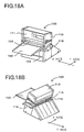
- the lateral cutter blade 110 is slidably supported on a bar 114 laid across the width of the main unit 113 at the side to which the laminate 109 is transported by the nip rollers 107, 108 as shown in Figs. 18A and 18B and 19.
- the blade 110 may be slid in the width (x-axis) direction to cut the laminate 109 along the end edge in the width direction at an arbitrary position in the send-out direction (Y-axis direction).
- the laminating apparatus 100 constructed as above is used in the following manner. At first, when the medium 101 such as a card placed on the feed tray 102 is pushed forward, the front end of the medium 101 is guided to between the non-adhesive sheet 103 and the adhesive sheet 104 unreeled from the upper and lower rolls 105 and 106 respectively and to a nip position between the nip rollers 107 and 108.
- the medium 101 is transported together with the sheets 103 and 104 into between the nip rollers 107 and 108 while laminating them, and sent out as the laminate 109. Thereafter, the laminate 109 is cut by means of the lateral cutter blade 110 in the width direction, thus providing a resultant laminate 109 constructed of the medium 101 whose both surfaces are covered by the sheets 103 and 104.
- the sheets 103, 104 may have slack.
- the rotation of the handle 115 is in direct conjunction with the rotation of the nip rollers 107, 108. Accordingly, this may cause the occurrence of slack in the sheets 103, 104 according to the manner of rotating the handle 115 by a user. If a mechanism of preventing backward rotation of the rollers 107, 108 is provided between the handle 115 and the rollers 107, 108, the sheets 103, 104 unreeled from the upper and lower rolls 105, 106 could be temporarily made tense, but not kept as stretched. This also would result in the occurrence of slack in the sheets 103, 104.
- the sheets 103, 104 are fed first by a predetermined length in order to remove the slack generated in the sheets 103, 104. This case may cause a wasteful consumption of the sheets 103, 104 and an increase in production cost of the laminate 109.
- the medium or paper 101 placed on the feed tray 102 and the guide plate 112 is inserted to the nip position between the rollers 107, 108, and the handle 115 is rotated by the corresponding turns to the length in an Y-axis direction of the medium 101.
- the lateral cutter blade 110 is made to scan the laminate 109 in the X-axis direction to provide the desired laminate 109.
- a user should manually operate the apparatus 100 to produce the laminate 109 while confirming all of the producing steps. This gives extremely large labors and loads to the user.
- the present invention has been made in view of the above circumstances and has an object to overcome the above problems and to provide a laminating apparatus capable of removing slack generated in the sheets unreeled from sheet rolls to minimize wasteful consumption of the sheets, preventing the occurrence of wrinkles in the medium or sheets, and aesthetically laminating the medium.
- Another object of the present invention is providing a laminating apparatus capable of simplifying the steps needed to produce a laminate and producing a laminate according to a medium to be laminated, thereby to reduce labors or loads exerted on a user.
- a laminating apparatus for producing a laminate by unreeling sheets from a sheet roll containing long lengths of rolled sheet, and laminating the sheet on a document medium, while feeding the laminated sheet and document medium
- the apparatus including: a controller for controlling the laminating apparatus; a power supply part for supplying power to the controller; a sheet roll holding part for holding the sheet roll; a sheet roll detecting part for detecting mounting and dismounting of the sheet roll with respect to the sheet roll holding part; a first flag memory that is set when the power supply part starts supplying power to the controller; a second flag memory that is set when the sheet roll detecting part detects the mounting and dismounting of the sheet roll; and a slack removing device that performs a slack removing operation to remove slack generated in the sheet unreeled from the sheet roll only if the first or second flag memory has been set.
- the operation of removing slack from the sheet roll is performed by means of the slack removing device only if the first flag memory is set to an on state at the start of power supply from the power supply part to the control part, or if the second flag memory is set to the on state at the detection of dismounting and mounting of the sheet roll by the sheet roll detector. Accordingly, the slack removing device is operated to conduct the slack removing operation with respect to the sheet roll only when the first or second flag has been set to the on state, so that a wasteful consumption of the sheets can be prevented. Also, the occurrence of wrinkles in the sheet and the document medium can be prevented, to aesthetically laminate the medium.
- a laminating apparatus for producing a laminate by laminating sheets on both faces of a document medium
- the apparatus including: a document medium feeding part for supplying the document medium into a main body of the laminating apparatus; a laminate feeding part for laminating the sheets on both faces of the document medium to form a laminate while feeding the laminate in a predetermined feeding direction; a first detecting part disposed near the document medium feeding part, for detecting presence of the document medium fed by the document medium feeding part; a first cutting part disposed downstream from the laminate feeding part along the feeding direction, the first cutting part being movable in a direction of a width of the laminate, perpendicular to the feeding direction, to determine a cutting position of the laminate, and the first cutting part cutting the laminate in the feeding direction; a second cutting part disposed downstream from the laminate feeding part along the feeding direction, the second cutting part setting a cutting position of the laminate based on a detection result of the first detecting part and cutting the laminate in the width direction; and at
- the document medium feeding part, the laminate feeding part, and the second cutting part are operated by means of the drive motor to feed the document medium and/or the laminate and then cut the laminate based the detection result of the first detecting part. Accordingly, with the laminating apparatus constructed as above, a user does not need to manually operate a handle and the like while visually observing all the steps of producing the laminate. Thus, labors and loads which would be exerted on the user can be reduced.
- FIG. 1 is a perspective view of the laminating apparatus.
- Fig. 2 is a partial top view of a control panel of the apparatus.
- Fig. 3 is a perspective view of the apparatus with a top cover opened.
- Fig. 4 is an enlarged top view of a sheet cassette holding part in the apparatus.
- a laminating apparatus 1 has a box-like housing 3 provided at the backside thereof (a left side in Fig. 1) with a paper tray 7 on which paper 5 (see Fig. 5) such as documents or cards to be laminated are placed.
- the paper tray 7 is disposed at a slope.
- a paper guiding part 8 is integrally provided next to the tray 7. This guiding part 8 includes at both sides a pair of paper guides 9A, 9B for restricting movement of the paper 5 placed on the tray 7 in a direction of the width thereof (which is hereinafter referred to as an X-axis direction).
- the paper guide 9A is fixedly formed into one body with the guiding part 8, while the paper guide 9B is movably attached to the guiding part 8. This guide 9B is in engagement with a groove 9C formed in the part 8.
- the fixed paper guide 9A is used to guide a side edge (a right edge in Fig. 1) of the paper 5.
- the movable guide 9B is moved along the groove 9C to a position where the guide 9B comes into contact with the other side edge (a left edge in Fig. 1) of the same, thereby to guide the other side edge according to the width of the paper 5. It is to be noted that the paper 5 fed from the paper tray 7 through the paper guiding part 8 and the guides 9A, 9B is transported to a sheet supply area II (see Fig. 5) which will be mentioned later.
- a sheet cassette holding part 32 for receiving a sheet cassette (see Fig- 3).
- a top cover 13 is rotatably attached to the housing 3 to open or close the sheet cassette holding part 32.
- the cover 13 is provided with a projection 14 on the underside as shown in Fig. 3.
- the projection 14 is arranged in correspondence with an open/close switch 18 (see Fig. 6) disposed under a switching hole 16 formed in a front side (a lower side in Fig. 3) of the housing 3.
- the cover 13 is closed, the projection 14 is inserted into the switching hole 16 to turn the switch 18 to the on state.
- the projection 14 is removed from the switching hole 16 to turn the switch 18 to the off state.
- the cover 13 is also provided with a transparent window 37 for allowing a user to visually confirm whether the sheet cassette 31 is mounted in the holding part 32.
- a control panel 11 for instructing or selecting various operations of the laminating apparatus 1 is arranged on the top of the housing 3 adjacent to the top cover 13 (in the right side in Figs. 1 and 3).
- Those buttons and/or switches are operated by a user to produce a laminate 57 as desired.
- the power switch 17 is used for turning on/off the power of the laminating apparatus 1 under the condition that the apparatus 1 is powered through a plug of a power supply part 85 mentioned later connected with an outlet of a utility power source. It is to be noted that the apparatus 1 is powered from the utility power source through an AC adapter not shown that converts utility power (current) into a direct current (DC).
- the manual feed button 21 and the manual cutting button 19 are used for forming a laminate 57 in accordance with operator's purposes irrespective of shapes of paper 5 to be laminated.
- the buttons 21 and 19 are also used for discharging outward and cutting a part of a laminate 57 if troubles such as a jamming arise in the laminate part between a pair of press rollers 53, 55 during rotation to laminate the paper 5 with the first and second sheets 27 and 29 unreeled from a first and second sheet rolls 65 and 67 each containing long lengths of rolled continuous sheet.
- the start-stop button 23 is used for automatic formation of a laminate 57 according to the shape and size of paper 5 to be laminated (an automatic formation mode).
- the cutting mode selection switch 25 is used for selecting a mode from among a margin mode in which a laminate 57 is cut with margins around the laminated paper 5, a non-margin mode in which a laminate 57 is cut to the size of the paper 5 with no margin around the laminated paper 5, and other modes.
- the X-axis cutter 45 to be slid in a width direction of paper 5 and a Y-axis cutter pair 40 (which includes a first and second Y-axis cutter blades 41 and 42) to be slid in a lengthwise direction of paper 5 are selectively operated.
- the housing 3 has a discharge part 63 in the front thereof. Through this discharge part 63, a laminate 57 made of paper 5 laminated between the first and second sheets 27, 29 is discharged to the outside of the apparatus 1. At a corner of the housing 3 (the right corner in Figs. 1 and 3), the housing 3 is also provided with a part 15 for removing sharp corners of the discharged laminate 57. Specifically, this corner-removing part 15 is used to trim away the sharp corners of the square laminate 57 to have round corners.
- Fig. 5 is a side sectional view of the laminating apparatus 1.
- the apparatus 1 includes a paper supply area I, a sheet supply area II, a laminate formation area III, a cutting area IV, and a discharge area V, which are aligned in this order from an upstream side in a paper feeding direction.
- the paper 5 placed on the tray 7 is guided by the guides 9A, 9B and fed from the guide part 8 to the sheet supply area II.
- a paper feed roller pair 50 constructed of a paper feed roller 49 for feeding paper and a driven roller 51.
- the feed roller 49 is connected to a drive motor 75 (see Fig. 6) through a gear mechanism. When rotated by actuation of the drive motor 75 and the gear mechanism, the feed roller 49 operates in cooperation with the driven roller 51 to feed the paper 5 downstream.
- the sheet cassette holding part 32 In the downstream from the paper feed roller pair 50, the sheet cassette holding part 32 is provided for receiving the sheet cassette 31 which will be mentioned later.
- the structure of the sheet cassette holding part 32 is described below, referring to Fig. 4.
- This part 32 has a concave space in which the cassette 31 is inserted, and a cassette discrimination sensor 47 such as a microswitch and the like is installed on the bottom wall of the part 32.
- the sensor 47 is to discriminate the types of the sheet cassette 31 (e.g., sizes and lengths in an x-axis direction) inserted in the holding part 32. For example, when the sheet cassette 31 containing sheets of an A4-sized width is inserted, the bottom wall of the cassette 31 contacts and pushes the sensor 47 to switch it to the on state.
- the sensor 47 when the cassette 31 containing sheets of an A6-sized width is inserted, which is so small that the bottom wall does not come into contact with the sensor 47, the sensor 47 remains off. Based on the on/off state of the sensor 47, the size of the cassette 31 inserted in the holding part 32 can be detected.
- a sensor 69 for detecting a length of paper 5 in an Y-axis direction (in Fig. 4) is disposed in an upper side of the rear wall of the holding part 32.
- This Y-axis length sensor (referred to as a Y-axis sensor hereinafter) 69 is switched to the on state by the contact with the top end of the paper 5 fed from the paper supply area I.
- the sensor 69 remains on during feed of the paper 5, and then will be switched to the off state when the bottom end of the paper 5 is transported past the sensor 69.
- the length of the paper 5 can be determined by calculation of the number of rotations of the drive motor 75 for a period of time from the on to off states of the Y-axis sensor 69 and correlation of the calculated number of rotations of the drive motor 75 with the length of the transported paper 5.
- the structure of the sheet cassette 31 is described below with reference to Fig. 5.
- This cassette 31 holds therein two rotatable sheet rolls; the first sheet roll 65 and the second sheet roll 67, which are vertically aligned.
- the first roll 65 comprises a first sheet 27 made of polyethylene terephthalate (PET) film with an adhesive applied to one face thereof.
- PET polyethylene terephthalate
- the second roll 67 comprises a second sheet 29 made of PET film with an adhesive applied to one face thereof and rolled with the adhesive applied face inside.
- the first and second sheets 27, 29 are unreeled from the sheet cassette 31 by rotation of the press roller pair 54 arranged in the laminate formation area III so that the adhesive applied faces of the sheets 27, 29 are face to face with each other, as shown in Fig. 5.
- the sheets 27, 29 are adhesively laminated on both faces of the paper 5 fed into the cassette 31 by means of the paper feed roller pair 50.
- an encoder plate 66 with a predetermined slit pattern is attached on an end face of the first sheet roll 65, as shown in Fig. 5, an encoder plate 66 with a predetermined slit pattern is attached.
- a photosensor 68 is also installed on a side wall of the holding part 32 near the encoder plate 66. This photosensor 68 is to detect the slit pattern of the encoder 66 which is rotated concurrently with rotation of the first roll 65, and thus to generate a detection signal.
- This detection signal from the photosensor 68 can be used for removal of slack generated in the first and second sheets 27, 29 and for detection of the types of the first and second sheet rolls 65, 67 and the ends of the sheets 27, 29, i.e., the exhaustion of those sheets.
- the structures of the encoder plate 66 and the photosensor 68 are substantially the same as disclosed in Japanese patent unexamined publication No. 2000-37775.
- a pair of right and left locking members 33 is arranged above the cassette 31 and downstream in the paper feeding direction.
- a cassette pressing member 34 is provided at about the midpoint between the locking members 33 and operated together with the locking members 33.
- Each of the locking members 33 is connected to a release lever 35 (only one lever is shown in Fig. 3).
- the cassette pressing member 34 presses the sheet cassette 31 inserted in the holding part 32, locking the cassette 31 in position.
- an arm 43 (mentioned later) is moved to a left end in Fig. 3 and the release levers 35 are operated to release the lock of the locking members 33.
- the pressing force of the cassette pressing member 34 exerted on the cassette 31 is released, which permits a user to lift the sheet cassette 31 out of the holding part 32.
- the apparatus is configured such that when the pressing force of the pressing member 34 is released, a clearance is produced between a drive roller 53 and a driven roller 55 of the press roller pair 54 which will be mentioned later in detail.
- a clearance is produced between a drive roller 53 and a driven roller 55 of the press roller pair 54 which will be mentioned later in detail.
- the structure of the laminate formation area III is described below.
- the press roller pair 54 is arranged.
- This roller pair 54 comprises the drive roller 53 (a lower roller) and the driven roller 55 (an upper roller), which are vertically aligned.
- the drive roller 53 is connected to the drive motor 75 through a gear train and the like.
- the drive roller 53 when rotated by actuation of the motor 75 operates in cooperation with the driven roller 55 to unreel the first and second sheets 27, 29 from the cassette 31 while sandwiching the paper 5 passing through the cassette 31 between the first and second sheets 27, 29 having the adhesive layers, thereby laminating them.
- a laminate 57 is produced.
- a cassette sensor 56 is arranged downstream from the press roller pair 54 in the Y-axis direction. This sensor 56 detects the presence or absence of the cassette 31 in the holding part 32 by detecting the presence or absence of the tip ends of the first and second sheets 27, 29 held between the press roller pair 54 when the cassette 31 is mounted in the holding part 32 as mentioned above. A detection signal generated by the cassette sensor 56 is used for a determination in an interrupt processing (see Fig. 7) to detect whether mounting and dismounting of the cassette 31 was made.
- the structure of the cutting area IV is described below.
- this area IV there are basically provided an X-axis cutter 45 for cutting the laminate 57 formed in the above manner in a width direction (X-axis direction) and a Y-axis cutter pair 40 for cutting the laminate 57 in a lengthwise direction (Y-axis direction).
- the X-axis cutter 45 is described first.
- This cutter 45 is constructed of a circular rotary blade mounted in a carriage movable on a frame attached to the apparatus 1 in a width direction thereof and a fixed blade mounted on the frame in correspondence with the rotary blade.
- the rotary blade and the fixed blade operate to cut the laminate 57 in the width direction.
- the Y-axis cutter pair 40 comprises the first and second Y-axis cutter blades 41, 42.
- the first Y-axis cutter blade 41 is fixed to an end of the arm 43 (corresponding to the downstream end of the press roller pair 54) upward bent over the cassette 31 mounted in the holding part 32.
- the blade 41 is movable in the width direction (X-axis direction) of the apparatus 1.
- the second Y-axis cutter blade 42 is aligned with the first blade 41 in the X-axis direction.
- the arm 43 to which the first Y-axis cutter blade 41 is attached is movable in the X-axis direction by activation of a motor.
- An X-axis length sensor (referred to an x-axis sensor hereinafter) 39 is attached to the other end of the arm 43 (corresponding to the upstream end of the feed roller pair 50) for detecting the width of the paper 5 in the X-axis direction.
- the arm 43 is normally placed in a left position (home position) as shown in Fig. 4. To detect the width of the paper 5 by the use of the X-axis sensor 39, the following process is performed.
- the arm 43 When the Y-axis sensor 69 detects the presence of the top end of the paper 5, the arm 43 is moved from the home position in the X-axis direction until the sensor 39 detects the presence of the left edge (in Figs. 1 and 4) of the paper 5. At this time, the right edge of the paper 5 is in contact with the guide 9A. Also, a first distance between the guide 9A and the home position of the arm 43 is determined in advance. A second distance between the home position and the left edge of the paper 5 is calculated based on the number of rotations of the motor required to move the arm 43 until the sensor 39 detects the left edge of the paper 5. This second distance is subtracted from the first distance and the width of the paper 5 is obtained.
- the arm 43 is moved to a position where the x-axis sensor 39 detects the left edge of the paper 5.
- the first and second Y-axis cutters 41, 42 are set to respective positions separate from each other so that the laminate 57 is cut with margins on both sides of the laminated paper 5.
- the first and second Y-axis cutters 41, 42 are set by means of the operating mechanism to respective positions closer to each other than in the margin mode.
- the first and second Y-axis cutters 41, 42 are movable in a vertical, namely, Z-axis direction by means of a motor, a cam mechanism, and the like. With the cutters 41, 42 positioned down, when the laminate 57 is fed in a Y-axis direction by the rotation of the press roller pair 54, the side margins of the laminate 57 (both sides of the paper 5) are cut out along the side edge in the Y-axis direction.
- This Y-axis cutter pair 40 like the case of the X-axis cutter 45, is substantially the same as in Japanese patent unexamined publications Nos. 11-245299, 11-245296, and 11-245297. The detailed description thereof is referred to the applications and omitted in this specification.
- the laminate discharging area V is explained below.
- a discharge roller pair 60 constructed of a discharge roller 59 and a driven roller 61.
- the discharge roller 59 is rotated by actuation of the drive motor 75 to discharge in cooperation with the driven roller 61 the finished laminate 57 that has been cut to a desired size by the x-axis cutter pair 45 and the Y-axis cutter pair 40 to the outside of the laminating apparatus 1 through a discharge opening of the discharge part 63.
- Fig. 6 is a block diagram of the control system.
- the control system in the present embodiment is configured such that a CPU 83 is arranged as a core. Connected to the CPU 83 through a bus line 81 are the control panel 11, a ROM 71, a RAM 72, the drive motor 75, the open/close switch 18, the cassette sensor 56, the X-axis sensor 39, the Y-axis sensor 69, the cassette discrimination sensor 47, the photosensor 68, and the power supply part 85.
- This power supply part 85 is provided with a plug connectable with an outlet of a utility power source and used for supplying a direct current (DC) to the apparatus 1 through an AC adapter that converts utility power (current) into a direct current.
- DC direct current
- the power switch 17 on the control panel 11 is used for powering on/off the laminating apparatus 1 under condition that power is supplied to the apparatus 1 through the plug connected with the outlet of the utility power source.
- the CPU 83 Upon press of the manual cutting button 19, the CPU 83 causes the X-axis cutter 45 to cut the laminate 57.
- the CPU 83 Upon press of the manual feeding button 21, the CPU 83 causes the press roller pair 54 and the discharge roller pair 60 to feed the laminate 57.
- the CPU 83 causes the press roller pair 54 to start or stop a laminating operation.
- the ROM 71 stores a monitoring program mentioned later for monitoring an opened/closed state of the top cover 13 according to an on/off signal of the open/close switch 18, a slack removable processing program mentioned later for removing slack generated in the first and second sheets 27, 29, and other various programs required for control of the laminating apparatus 1.
- the CPU 83 operates to perform various processing operations in accordance with the programs stored in the ROM 71.
- the RAM 72 is the memory for temporarily storing various data calculated in the ROM 71.
- a cassette replacement flag 72A that will be set to an on state at an interrupt processing for performing the processing to monitor the opened/closed state of the top cover 13, and a cold flag 72B that will be set to an on state at a cold start at which the power supply part 85 starts power supply to the laminating apparatus 1.
- the drive motor 75 is used for rotating the feed roller pair 50, the press roller pair 54, and the discharge roller pair 60.
- the CPU 83 controls each rotation of those roller pairs as required.
- the photosensor 68 detects a slit pattern formed on the encoder plate 66 attached to the end face of the first sheet roll 65. Based on the detection result, the photosensor 68 outputs a predetermined rectangular pulse to the CPU 83. Upon receipt of the rectangular pulse, the CPU 83 monitors the amount of slack to be removed from the first and second sheets 27, 29 in the slack removal processing.
- the cassette discrimination sensor 47 is switched to the on or off state according to the size of the sheet cassette 31 inserted in the holding part 32.
- the CPU 83 then detects the size of the cassette 31 according to the on/off signal from the sensor 47.
- the photosensor 56 detects the presence of the tip ends of the first and second sheets 27, 29 held between the press roller pair 54 when the cassette 31 is mounted in the holding part 32. Based on the detection signal from the cassette sensor 56, the CPU 83 monitors whether or not the cassette 31 is dismounted from and mounted in the holding part 32.
- the X-axis sensor 39 detects the side edge (the left edge in Fig. 4) of the paper 5 when the arm 43 is moved from the home position. Based on the number of rotations of the motor required to move the arm 43, the CPU 83 calculates a distance between the home position and the side edge of the paper 5 (i.e., the second distance), and then subtracts the calculated distance from a distance between the home position and the other side edge of the paper 5 (which is in contact with the guide 9A) (i.e., the first distance), thereby to calculate the width of the paper 5.
- the Y-axis sensor 69 detects the top and bottom ends of the paper 5. The CPU 83 determines the length of the paper 5 according to the on/off signal from the sensor 69.
- Fig. 7 is a flowchart of a control processing program of the laminating apparatus 1.
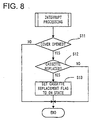
- Fig. 8 is a flowchart of an interrupt processing program.
- Fig. 9 is a flowchart of a slack removal processing program.
- step S2 This judgement in S1 is executed depending on whether or not the plug of the power supply part 85 is connected with the outlet of the utility power source. If the plug is not connected with the outlet (S1: NO), the CPU is set in a standby state until the plug is connected with the outlet. If power supply from the utility power source to the apparatus 1 is started (S1: YES), the cold flag 72B is set to the on state in S2. Then, the RAM 72 is initialized (S3) and the interrupt processing is started (S4) in sequence.
- the interrupt processing in S4 is explained below with reference to Fig. 8.
- This interrupt processing is executed for determining whether or not the sheet cassette 31 is dismounted from and mounted in the holding part 32 during power supply from the utility power source.
- the first check is made as to whether or not the top cover 13 is opened. This is determined according to whether the open/close switch 18 is turned to the off state by the projection 14 removed from the switch hole 16 when the top cover 13 is opened. If the top cover 13 is not opened, namely, the switch 18 remains on (S11: NO), it is determined that the sheet cassette 31 was not dismounted and mounted. The interrupt processing is then terminated.
- the cassette replacement flag 72A is set to the on state when the sensor 56 detects the dismounting and mounting of the cassette 31 with respect to the holding part 32.
- the slack removal processing ends. In this case, the first and second sheets 27 and 29 are not subjected to the slack removal operation.
- the press roller pair 54 is actuated first to unreel the first and second sheets 27 and 29 from the sheet cassette 31.
- the CPU 83 monitors whether the photosensor 68 outputs a rectangular pulse based on detection of the slit pattern of the encoder 66 in rotating as rotation of the first sheet roll 65.
- the photosensor 68 detects the predetermined number of rectangular pulses, for example, one pulse, by an encoder detection (S17:YES), it is determined that the slack generated in the first and second sheets 27 and 29 has been removed. The flow is then advanced to S19.
- the photosensor 68 does not detect any rectangular pulse (S17:NO)
- the predetermined length of the sheets 27 and 29 is not fed (S18:NO)
- the flow returns to S17 where the photosensor 68 detects a rectangular pulse. It is to be noted that the feeding length of the sheets 27 and 29 is not limited to 15mm, and it may be freely determined.
- the press roller pair 54 is actuated in response to a command input from the control panel 11 in S8, thereby starting a laminate formation processing for sandwiching the paper 5 between the first and second sheets 27 and 29 to laminate them.
- S9 a determination is made as to whether the power switch 17 is pressed to turn off the power. If it is turned off (S9:YES), the flow advances to the following step S10. If not (S9:NO), the flow returns to S6.
- S10 it is determined whether or not power supply from the utility power source through the power supply part 85 is stopped. This determination is made according to whether the plug of the power supply part 85 is disconnected from the outlet of the utility power source. When the power supply is stopped (S10:YES), the lamination processing control ends. When the power supply is maintained (S10:NO), the flow returns to S5.
- the above-mentioned laminating apparatus 1 in the first embodiment is arranged such that the cold flag 72B is set to the on state (52) upon start of the power supply from the utility power source through the power supply part 85 (S1:YES); the cassette replacement flag 72A is set to the on state (S13) when the cover 13 is opened and thus the cassette sensor 56 is switched on from off (S11:YES); and the slack removal processing to the first and second sheets 27 and 29 is executed (S7, S16-S19) only if the flag 72B or 72A is in the on state (S14:YES, S15:YES) at the time of power-on of the apparatus by the use of the power switch 17 (S5:YES).
- the slack removal operation is made on the minimum area required to remove slack from the sheets 27 and 29. This can minimize wasteful consumption of the sheets and aesthetically laminate the paper 5 without causing the occurrence of wrinkles in the paper 5 or the sheets 27 and 29.
- the laminating apparatus 1 in the first embodiment is also arranged such that the encoder plate 66 having a predetermined slit pattern is attached to the end face of the first sheet roll 65.
- the photosensor 68 detects the slit pattern of the encoder plate 66 during rotation of the first sheet roll 65.
- the CPU 83 In the slack removing operation, after the start of feed of the sheets 27 and 29 from the cassette 31 by means of the press roller pair 54 (S16), when the CPU 83, monitoring as to whether a rectangular pulse is output from the photosensor 68 in association with the rotation of the first sheet roll 65, detects the output of the predetermined number of rectangular pulses (for example, one pulse) from the photosensor 68 (S17:YES), determining that the slack in the sheets 27 and 29 has been removed, the CPU 83 terminates the slack removal operation (S19).
- the consumption of the sheets 27 and 29 can be extremely reduced as compared with the case where the sheets 27 and 29 are unreeled and fed by a fixed length every power-on of the apparatus by the power switch 17. This can achieve large reduction in manufacturing cost of the laminate 57.
- the laminating apparatus 1 in the first embodiment is arranged such that, after the slack removing operation to the first and second sheets 27 and 29 is performed upon press of the power switch 17 during power supply to the apparatus 1 from the utility power source through the power supply part 85 (S1-S7, S14-S18), the cold flag 72B and the cassette replacement flag 72A are reset to an off state (S20). Under power supply, even when the switch 17 is pressed to turn off the power (S9, S10:NO) and subsequently pressed again to turn on the power (S5:YES), the flags 72B and 72A being kept in the off state (S14:NO, S15:NO), the slack removing operation to the first and second sheets 27 and 29 is not conducted. This can avoid any problem that would be caused by a slack removing operation conducted every power-on of the apparatus by the power switch 17 and thus can prevent wasteful consumption of the sheets.
- first and second sheets 27 and 29 of the first and second sheet rolls 65 and 67 accommodated in the sheet cassette 31 in the above embodiment are applied with an adhesive
- both of the sheets do not necessarily need the application of adhesive. That is, it is sufficient only that at least one of the sheets is applied with an adhesive.
- the encoder plate 66 is attached to the end face of the first sheet roll 65, but it may be attached to the end face of the second sheet roll 67.
- the photosensor 68 is disposed in the second sheet roll 67 side.
- a second embodiment of the laminating apparatus according to the present invention will be described below. It is to be noted that the structure of the apparatus in the second embodiment has substantially the same as that in the first embodiment. Like elements corresponding to those in the first embodiment are indicated by like numerals and the detail thereof is therefore omitted.
- a sheet cassette 31 in the second embodiment includes a plurality of types adapted for a first and second sheets 27 and 29 with different lengths in an X-axis direction.
- a user can select a sheet cassette 31 corresponding to the X-axis length of paper 5 to be laminated.
- a transparent window 37 arranged near the center of a cover 13 allows the user to easily confirm the type of the cassette 31 from a label and the like not shown attached to the cassette 31 which shows the X-axis lengths of the first and second sheets 27 and 29, even when the cover 13 is closed (see Fig. 1).
- the laminating apparatus 1 in the second embodiment also has five areas I-V via which paper 5 is laminated into a desired laminate 57.
- an X-axis sensor 39 and a Y-axis sensor 69 In the paper supply area I, there are provided an X-axis sensor 39 and a Y-axis sensor 69.
- the X-axis sensor 39 is placed upstream in an Y-axis direction from a paper feed roller 49 and a driven roller 50.
- the sensor 39 is used for determining the X-axis length of paper 5 by detecting the presence of the paper 5 while an arm 43 scans in the X-axis direction.
- the Y-axis sensor 69 is placed downstream in an Y-axis direction from a paper supply roller pair 50.
- the sensor 60 is used for determining the Y-axis length of the paper 5 by detecting the presence of the paper 5.
- these X- and Y-axis sensors 39 and 69 enables precise determination of the X-axis and Y-axis lengths of the paper 5 supplied to the area I.
- the sheet cassette 31 constructing a sheet supply area II rotatably holds therein a first and second sheet rolls 65 and 67. These rolls 65 and 67 comprise the first and second sheets 27 and 29 respectively.
- Each of the sheets is made of belt-like long length of a synthetic resin film such as a polyethylene terephthalate (PET) film applied with an adhesive on one face thereof and is rolled with the adhesive face inside.
- PET polyethylene terephthalate
- the sheets 27 and 29 are arranged such that the adhesive faces come into contact with the paper 5 to be laminated. It is to be noted that the adhesive may be applied to only one of the first and second sheets 27 and 29, instead of both sheets.
- the sheets 27 and 29 may be constructed as follows: one of the sheets 27 and 29 is made of a magnetic film for enabling attachment of a laminate 57 to a metal plate; or one of the sheets 27 and 29 is applied with an adhesive on both faces thereof and a relesable sheet provided on the face that will be an outer face of a laminate 57, which enables adhesive attachment of the laminate 57 to a desired object.
- the first sheet roll 65 accommodated in the sheet cassette 31 is provided, on the side face, with a slit pattern with black and white lines radially extended about an axial center of the roll 65.
- a sheet discrimination sensor 87 (see Fig. 10) disposed near the first sheet roll 65 detects the slit pattern, which enables recognition of the rotational condition of the first sheet roll 65 or discrimination of the type and the like of the sheet cassette 31 (see Japanese patent unexamined publication No. 2000-37775).
- the slit pattern may be provided to the end face of the second sheet roll 67.
- the sheet discrimination sensor 87 should be arranged near the roll 67 to determine the rotational condition of the first sheet roll 65 or discriminate the types and the like of the sheet cassette 31.
- a marking whereby a feeding condition of the first sheet 27 and/or the second sheet 29 may be applied to both ends of the first sheet 27 and/or the second sheet 29 in the X-axis direction.
- the apparatus should be arranged to determine the rotational condition of the first sheet roll 65 and/or the second sheet roll 67 based on detection results on the marking(s) (see Japanese patent unexamined publication No. 11-348119).
- a Y-axis cutter pair 40 provided in a laminate cutting area IV is movable by means of a driving mechanism not shown in a vertical direction (which is perpendicular to the X-axis and Y-axis directions, and is referred to as a Z-axis direction hereinafter). With this cutter pair 40, the laminate 57 can be cut or not be cut as required.
- the laminating apparatus 1 can support the paper 5 having a length larger than the Y-axis length (about 90mm corresponding to the length of a business card) defined between the paper supply roller pair 50 and a press roller pair 54 constructed of a press roller 53 and a driven roller 55.
- the X-axis sensor 39 can detects the X-axis length of the paper in a range of 55-216 mm while the arm 43 scans in the X-axis direction. Accordingly, the laminating apparatus 1 can support the paper 5 having the size of 55-216 mm in X-axis length and 90 mm or more in Y-axis length.
- Fig. 10 is a block diagram of a control system of the apparatus 1.
- the laminating apparatus 1 is controlled by the following elements connected to a CPU 83 through a bus 81: a control panel 11 provided with a power switch 17, a manual cutting button 19, a manual feeding button 21, and a start-stop button 23 and others; a ROM 71 storing various programs such as a laminate formation processing program for commanding operations of each element, the program being executed at automatic formation of a laminate 57 according to the size of the paper 5 in response to start or stop of an automatic formation mode which is commanded by means of the start-stop button 23; a drive motor 75 for providing a driving power to the paper supply roller pair 50, the press roller pair 54, and a discharge roller pair 60 constructed of a discharge roller 59 and a driven roller 61; a timer 73 for counting times; a speaker 77 for informing a user of various errors and various receptions of inputs by ringing or sounding; an LED 79 for informing a user of various errors and various receptions of inputs by lighting up or blinking; the
- the CPU 83 performs, in addition of control of each element mentioned above, execution of processing; paper size measurement processing for determining the X-axis length of paper 5 from a scan amount (a distance) of the X-axis sensor 39 in the X-axis direction, required to detect the paper 5, and for determining a duration of on-time of the Y-axis sensor 69 and the Y-axis length of paper 5 from a driven amount (the number of rotations) of the paper feed roller 49 driven for the duration of on-time of the sensor 69; and error determination processing for detecting errors based on detection results by the X-axis sensor 39, the Y-axis sensor 69, the cassette discrimination sensor 47, and the sheet discrimination sensor 87 and others in cases where a laminate 57 conformable to the paper size could not be produced.
- a plurality of drive motors may be provided for driving those rollers and others in question.
- the laminate formation processing program is the program used for automatically producing a laminate 57 conformable to the size of the paper 5 to be laminated.
- This automatic formation processing can be stopped or restarted as required by means of the start-stop button 23.
- the automatic formation processing to be commanded with the start-stop button 23 there is provided a function of manually producing a laminate 57 according to user's purposes by means of the manual cutting button 19 and the manual feeding button 21.
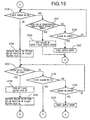
- the paper feed roller 49 is actuated to feed paper 5 so that the top end of the paper 5 can be detected by the Y-axis sensor 69 (S103).
- the paper 5 to be laminated is put on the feed tray 7 with the right end (in Figs. 3 and 4) of the paper 5 in contact with the right sidewall of the tray 7.
- the Y-axis sensor 69 is therefore disposed in the housing 3 to the right so that the paper 5 having a short X-axis length can be also detected.
- the Y-axis sensor 69 When the paper 5 is fed to a position where the Y-axis sensor 69 detects the top end of the paper 5 (S103), then the Y-axis sensor 69 confirms the presence of the paper 5 (S105). If the Y-axis sensor 69 does not detects the presence of the paper 5 (S105:NO), it is determined that no paper 5 is put on the feed tray 7 by the user. At this time, the speaker 77 and/or the LED 79 inform the user thereof (S107). Thus, the laminate formation processing ends.
- the arm 43 is moved to scan in the X-axis direction, and the X-axis sensor 39 attached to an end of the arm 43 detects the X-axis length of the paper 5 fed by the feed roller 49 (S109).
- the apparatus 1 in the present embodiment is arranged so that the X-axis sensor 39 can detect the paper 5 having an X-axis length being in a range of 55mm (about a business card length) to 216 mm (about A4-size paper), which correspond to the size of a laminate producible from the laminating apparatus 1.
- the first Y-axis cutter 41 is provided to the other end of the arm 43.
- the stop position of the arm 43 in the X-axis direction in S109 corresponds to the down position of the first Y-axis cutter 41.
- This down position of the cutter 41 is determined in association with cutting modes selected by the cutting mode selecting switch 25. As shown in Fig. 15, specifically, it corresponds to a position for cutting a laminate 57 at the outside of 4.5 mm from the side edge of the paper 5 in a margin mode (see Fig. 15A) and another position for cutting a laminate 57 at the inside of 1.5 mm from the side edge of the paper 5 in a non-margin mode (see Fig. 15B).
- the second Y-axis cutter 42 is moved to a down position by means of a driving mechanism not shown actuated in accordance with the cutting mode selected by the selecting switch 25.
- the X-axis length of the paper 5 After determination of the X-axis length of the paper 5 in S109, it is determined in S111 as to whether the X-axis length of the paper 5 lies within a predetermined range (55-216 mm). If the length is not within the range (S111:NO), it is determined that the paper 5 put on the feed tray 7 by the user has a size out of the size of a laminate producible from the apparatus 1.
- the speaker 77 and/or the LED 79 are actuated to inform to the effect to the user (S113), and the laminate formation processing ends.
- the X-axis length of the paper 5 lies within the predetermined range (S111:YES)
- the X-axis length of the first and second sheets 27 and 29 accommodated in the cassette 31 is detected through the cassette discrimination sensor 47 (S115). Thereafter, a determination is implemented on the relationship between the x-axis length of the sheets 27, 29 and that of the paper 5 detected in S9 (S117).
- the feed roller 49 is actuated to feed the paper 5 so that a distance between the top end of the paper 5 and the X-axis sensor 39 becomes equal to that minimum Y-axis length (S119). After such the actuation of the feed roller 49, a determination is made as to whether the paper 5 is detected through the X-axis sensor 39 (S121).
- the X-axis sensor 39 does not detect the paper 5 (S121:NO), it is determined that the formation of a laminate 57 is not enabled because the Y-axis length of the paper 5 is not correspondent with the minimum Y-axis length or more.
- the speaker 77 and/or the LED 79 are actuated to inform to the effect to the user (S122), and the laminate formation processing ends.
- the feed roller 49 is actuated until the paper 5 is fed so that the top end thereof reaches the nipping position between the press roller pair 54 (S127). Thereafter, the press roller 53 is actuated to feed the laminate 57 so that the top end thereof reaches the position where the Y-axis cutter pair 40 is moved down (S129) and the cutter pair 40 is moved down at that position to cut out both sides of the laminate 57 from the top end thereof (S131).
- the press roller 53 is further actuated to feed the laminate 57 to a position where the top end portion of the laminate 57 is cut by means of the X-axis cutter 45 (S133), thereby allowing the Y-axis cutter pair 40 to cut both sides in the X-axis direction of the laminate 57 along the Y-axis. Then, the press roller 53 is stopped and the X-axis cutter 45 is caused to scan, cutting the top end portion of the laminate 57 (S135). It is to be noted that the position of the cutter 45 to cut the top end portion of the laminate 57 is determined in association with the cutting mode selected by the cutting mode selecting switch 25. As shown in Fig.
- Fig. 15 corresponds to a position for cutting the laminate 57 at the outside of 4.5 mm from the top edge of the paper 5 in a margin mode (see Fig. 15A) and another position for cutting a laminate 57 at the inside of 1.5 mm from the top edge of the paper 5 in a non-margin mode (see Fig. 15B).
- the press roller 53 is actuated again (S137), and a determination is made as to the presence of paper 5 by means of the Y-axis sensor 69 (S139). If the presence of the paper 5 is detected (S139:YES), it is determined that the bottom end of the paper 5 has not fully come yet in the housing 3. In this case, that processing is continued. On the other hand, a determination is also made based on the on-time of the Y-axis sensor 69 as ;to whether the Y-axis length of the paper 5 reaches 350 mm or more (S141).
- Fig. 15 corresponds to a position for cutting the laminate 57 at the outside of 4.5 mm from the bottom edge of the paper 5 in a margin mode (see Fig. 15A) and another position for cutting a laminate 57 at the inside of 1.5 mm from the bottom edge of the paper 5 in a non-margin mode (see Fig. 15B).
- the laminating apparatus 1 in the second embodiment needs no handle or the like to be manually operated by a user while the user visually confirms all the steps of producing a laminate 57.
- the apparatus 1 provided with the Y-axis sensor 69 and the X-axis sensor 39 enables the formation of a laminate 57 conformable to the size of paper 5. This can remove the need to cut the laminated sheets 27, 29 that unnecessarily lie off the edge of the paper 5 with scissors or a cutter, thus resulting in a reduction in labors and loads which would be exerted on the user.
- the X-axis sensor 39 and the first Y-axis cutter 41 can be moved to scan in the X-axis direction of the paper 5 (S109). This makes it possible to set the cutting position by the first Y-axis cutter 41 on the basis of the position where the paper 5 is detected by the X-axis sensor 39. Accordingly, the presence of paper 5 in the X-axis direction and the cutting position by the fist Y-axis cutter 41 to the laminate 57 can be efficiently detected.
- the press roller 53 is stopped (S145) after feeding the paper 5 by a predetermined Y-axis length (about 350mm) (S141:YES). This can prevent continuous formation of laminates 57 which would be caused by detection failure of the Y-axis sensor 69. The wasteful consumption of the sheets 27, 29 can be prevented accordingly.
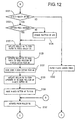
- the manual cutting button processing is started and a determination is made as to whether an error condition exists in the laminating apparatus 1 (S179). If an error exists (S179:YES), the time to be counted by the timer 73 is set for 2.0 seconds (S181). If no error exists (S179:NO), a determination is made as to whether the apparatus 1 is under condition that the automatic formation of the laminate 57 is temporarily stopped by press of the start-stop button 23 during the automatic formation mode (S183). If the automatic formation is temporarily halted (S183:YES), the timer 73 is set for 2.0 sec (S181). If no error exists (S179:NO) and the automatic formation of the laminate 57 is not temporarily stopped (S183:NO), the timer 73 is set for 0.5 sec (5185).
- the timer 73 is actuated to start counting the time (S187). Simultaneously, a determination is made as to whether the manual cutting button 19 is continuously kept in a pressed condition (S189). If the button 19 is not continuously pressed (S189:NO), it is determined that the cutting of the laminate 57 is not commanded by the button 19. This manual cutting button processing ends.
- S189 if it is detected that the button 19 is continuously kept in a pressed condition (S189:YES), a detection is made as to whether the duration of press of the button 19 reaches the time set in S181 or S185 (S191). If the duration of button press time does not reach the set time (S191:NO), the flow returns to S189 again.
- the laminating apparatus in the second embodiment is arranged such that while the feed roller 49 and the press roller 53 are stopped by means of the start-stop button 23, the duration of continuous press of the button 19 required for commanding the cutting of the laminate 57 by the X-axis cutter 45 is set for a longer one. This consequently makes it possible to prevent the occurrence of a problem that the laminate 57 may be cut through the carelessness of a user during temporary stop of the automatic formation of the laminate 57.
- the duration of continuous press of the button 19 required for commanding the cutting of the laminate 57 by the x-axis cutter 45 is set for a shorter one. This can prevent the occurrence of a problem that the cutting of the laminate 57 could not promptly be performed during the manual formation of the laminate 57.
- the duration of continuous press of the button 19 required for commanding the cutting of the laminate 57 by the x-axis cutter 45 is set for a longer one. This makes it possible to urge the user to appropriately determine or check the errors.
- the continuous press duration is set for a shorter one, thereby effectively solving a problem that the cutting of the laminate 57 could not promptly be performed during normal stop of production.
- a simple configuration of variously setting the continuous press duration of the button 19 can provide different commanding manners to cut the laminate 57, and can prevent a problem that the laminate 57 may be cut carelessly or involuntarily in a state that it should not be cut.
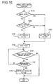
- Fig. 17 The manual cutting button processing in the following embodiment is substantially the same as that in the above embodiment. A different point therebetween is in that a different process of setting a duration of continuous press of a manual cutting button used for the cutting of a laminate 57. This is described below in detail.
- the CPU 83 calculates the position of the paper 5 based on detection results by the Y-axis sensor 69, thereby to determine whether the paper 5 exists in the position to be scanned by the X-axis cutter 45 (S195). If the presence of the paper 5 is detected in that position (S195:YES), the time to be counted by the timer 73 is set for 2.0 sec (S197). If the absence of the paper 5 is detected (S195:NO), the timer 73 is set for 0.5 sec (S199).
- the laminating apparatus 1 in this embodiment is arranged such that when the presence of the paper 5 in the cutting position of the laminate 57 by the X-axis cutter 45 is detected, the continuous press duration of the manual cutting button 19 is set for a longer one. At the cutting of the laminate 57 by the cutter 45, therefore, careless cutting of the paper 5 lying in the cutting position by the cutter 45 can be prevented. When the absence of the paper 5 in the cutting position is detected, the continuous press duration is set for a shorter one. The cutting of the laminate 57 can be promptly conducted, thus solving a problem that the cutting of the laminate 57 by the cutter 45 could not be executed even though the paper 5 does not exist in the cutting position of the laminate 57.
- a simple structure that the duration of pressing the manual cutting button 19 is differently set can provide different commanding manners to cut the laminate 57. It is furthermore possible to prevent a problem that the laminate 57 may carelessly be cut even though it should not be cut.
- the present invention may be embodied in other specific forms without departing from the spirit or essential characteristics thereof.
- the second embodiment exemplifies the case where the speaker 77 and/or the LED 79 are actuated to inform the user of the temporary stop of the automatic laminate formation or the occurrence of errors, but it is not limited thereto.
- the control panel 11 may be provided with a liquid crystal display for visually informing the user of the temporary stop of the automatic laminate formation or the occurrence of errors in images such as letters, pictures, and so on.
- the roller pairs 50, 54, 60 each of which is constructed of a pair of vertically aligned rollers are used as a feeding device to feed the paper 5 and the laminate 57. Those may be replaced with another feeding device if only it can smoothly feed the paper 5 and the laminate 57.
- a structure of a roller and a roller contact member can provide the same effect.
- the above embodiments exemplify the apparatus in which the first Y-axis cutter 41 and the X-axis sensor 39 are connected through the arm 43 so that the laminate cutting position by the cutter 41 is determined based on the detection result on the paper 5 by the sensor 39.
- another configuration may be used that the paper guide 9 is connected with the first Y-axis cutter 41 so that the laminate cutting position by the cutter 41 based on the position of the guide 9 in the X-axis direction.
- the second embodiment exemplifies the apparatus in which a determination is made through the Y-axis sensor 69 as to whether the paper 5 is fed by a predetermined Y-axis length or more (S141). The same effect can be obtained if such the determination is made through the X-axis sensor 39.
- the second embodiment exemplifies the apparatus in which the X-axis sensor 39 is disposed upstream from the feed roller 49 in the Y-axis direction, while the Y-axis sensor 69 is disposed downstream from the same, but it is not limited thereto. It is sufficient if only at least one of the sensors 39 and 69 is disposed upstream from the roller 49 in the Y-axis direction. Accordingly, if the paper 5 has a length that is so shorter in the Y-axis direction that the apparatus 1 can not support, the paper 5 can be prevented from being fed into the housing of the apparatus 1 by actuation of the feed roller 49. This can also provide the same effect as in the above embodiments.
- the sheets are laminated on both sides of the paper and the laminate is formed, it may be conceivable that the sheet is laminated on one side of the paper and the laminate is formed.
Landscapes
- Lining Or Joining Of Plastics Or The Like (AREA)
Abstract
Description
Claims (26)
- A laminating apparatus for producing a laminate by unreeling sheet from a sheet roll containing long lengths of rolled sheet, and laminating the unreeled sheet on a document medium, while feeding the laminated sheet and document medium, the apparatus including:a controller for controlling the laminating apparatus;a power supply part for supplying power to the controller;a sheet roll holding part for holding the sheet roll;a sheet roll detecting part for detecting mounting and dismounting of the sheet roll with respect to the sheet roll holding part;a first flag memory that is set when the power supply part starts supplying power to the controller;a second flag memory that is set when the sheet roll detecting part detects the mounting and dismounting of the sheet roll; anda slack removing device that performs a slack removing operation to remove slack generated in the sheet unreeled from the sheet roll only if the first or second flag memory has been set.
- The laminating apparatus according to claim 1, wherein the slack removing device includes a pair of rollers disposed downstream from the sheet roll holding part along a direction of feeding the laminate.
- The laminating apparatus according to claim 2 further including:a cover for opening and closing the sheet roll holding part;a cover switch for detecting opening and closing of the cover;wherein the sheet roll detecting part detects the mounting and dismounting of the sheet roll when an open state of the cover is detected by the cover switch.
- The laminating apparatus according to claim 3, wherein the sheet roll detecting part includes a sensor disposed downstream from the rollers along the laminate feeding direction, and a detection state of the sensor is changed when the sensor detects presence of tip end of the sheet held between the rollers.
- The laminating apparatus according to claim 4, wherein when the detection state of the sensor is changed, the sheet roll detecting part determines that the mounting and dismounting of the sheet roll was made.
- The laminating apparatus according to claim 2, 3, 4 or 5 further including:an encoder member provided with a predetermined slit pattern and attached to a side end of the sheet roll; andan encoder detecting part for detecting the slit pattern of the encoder member during rotation of the sheet roll to generate a predetermined detection signal;wherein when the detection signal is detected by the encoder detecting part, the slack removing device stops actuation of the rollers to terminate a slack removing operation with respect to the sheet roll.
- The laminating apparatus according to claim 6, wherein when the predetermined detection signal is not generated from the encoder detecting part, the slack removing device feeds the sheet by a predetermined amount by the rollers and stops actuation of the rollers to terminate the slack removing operation with respect to the sheet roll.
- The laminating apparatus according to any preceding claim further including:a power switch for powering on or off the laminating apparatus; anda plug for connecting the power supply part with an outlet of a utility power source;wherein the power supply part supplies power to the controller when the plug is connected with the outlet of the utility power source,during power supply through the power supply part to the controller, the second flag memory is set when the sheet roll detecting part detects that the mounting and dismounting of the sheet roll is made, and the slack removing device performs the slack removing operation only if the first or second flag memory has been set at a time when the laminating apparatus is powered by the power switch.
- The laminating apparatus according to claim 8 further including release means for releasing setting of the first or second flag memory after the slack removing operation is performed by the slack removing device with respect to the sheet roll;
wherein when the laminating apparatus is powered on by the power switch subsequently to powering-off during power supply through the power supply part to the controller, the setting of the first or second flag memory is released by the release means, and the slack removing device does not perform the slack removing operation with respect to the sheet roll. - The laminating apparatus according to any preceding claim further including:a document medium feeding part for supplying the document medium into a main body of the laminating apparatus;a laminate feeding part for laminating the sheets on both faces of the document medium to form a laminate while feeding the laminate in a predetermined feeding direction;a first detecting part disposed near the document medium feeding part, for detecting presence of the document medium fed by the document medium feeding part;a first cutting part disposed downstream from the laminate feeding part along the feeding direction, the first cutting part being movable in a direction of a width of the laminate form, perpendicular to the feeding direction, to determine a cutting position of the laminate, and the first cutting part cutting the laminate in the feeding direction;a second cutting part disposed downstream from the laminate feeding part along the feeding direction, the second cutting part setting a cutting position of the laminate based on a detection result of the first detecting part and cutting the laminate in the width direction; andat least a drive motor for actuating the document medium feeding part, the laminate feeding part, and the second cutting part.
- The laminating apparatus according to claim 10 further including a second detecting part disposed near the document medium feeding part, for detecting presence of the document medium in the width direction thereof;
wherein the first cutting part sets the cutting position of the laminate by actuating the drive motor based on a detection result of the second detecting part. - The laminating apparatus according to claim 11 further including a connecting member for connecting the second detecting part with the first cutting part;
wherein the second detecting part and the first cutting part are moved together when the connecting member is moved in the width direction of the document medium. - The laminating apparatus according to claim 11 or 12 further including:a recognizing part for recognizing a length of the sheets in the width direction; anda judging part for judging whether production of the laminate is enabled by comparing the width of the document medium detected by the second detecting part and the width of the sheets recognized by the recognizing part.
- The laminating apparatus according to claim 13, wherein at least one of the first and second detecting parts is disposed upstream from the document medium feeding part along the feeding direction, and
judging part judges whether the production of the laminate based on the detection result of the first or second detecting part with respect to the document medium when the document medium is fed by a first feeding amount by the document medium feeding part. - The laminating apparatus according to claim 14, wherein when the first or second detecting part detects presence of the document medium when the document medium is fed by a second feeding amount that is larger than the first feeding amount, the document feeding part and the laminate feeding part are stopped operating.
- The laminating apparatus according to any one of claims 10 to 15 further including:a manual feeding command part for selectively commanding start and stop of actuation of the document medium feeding part and the laminate feeding part; anda manual cutting command part for commanding cutting of the laminate with the second cutting part while the document medium feeding part and the laminate feeding part are stopped operating by means of the manual feeding command part.
- The laminating apparatus according to claim 16 further including:an automatic formation mode in which the drive motor is controlled to start and stop of actuation of at least the document medium feeding part, the laminate feeding part, and the second cutting part, performing start to end of formation of the laminate to automatically produce the laminate conformable to a length and width of the document medium; anda manual formation mode in which the document medium feeding part and the laminate feeding part are started or stopped operating by means of the manual feeding command part, and the second cutting part is operated by means of the manual cutting command part to cut the laminate while the document medium feeding part and the laminate feeding part are stopped operating, thereby to manually produce the laminate based on commands from the manual feeding command part and the manual cutting command part.
- The laminating apparatus according to claim 17 further including an automatic formation command part for commanding stop or restart of the automatic laminate formation during the start-to-end of laminate formation in the automatic formation mode;
wherein the manual cutting command part commands the second cutting part to cut the laminate in different manners between a first state where the document medium feeding part and the laminate feeding part are stopped by means of the automatic formation command part in the automatic formation mode and a second state where the document medium feeding part and the laminate feeding part are stopped by means of the manual feeding command part in the manual formation mode. - The laminating apparatus according to claim 18 further including a timer for counting a duration of a command given by the manual cutting command part;
wherein the manual cutting command part sets the duration to command the second cutting part to cut the laminate, the duration being different between the first and second states. - The laminating apparatus according to claim 19, wherein the command duration is set longer in the first state, while shorter in the second state.
- The laninating apparatus according to any one of claims 16 to 20 further including an error judging part for stopping actuation of the document medium feeding part and the laminate feeding part by determining that an error exists in laminate formation based on a judgement that formation of the laminate conformable to a length and width of the document medium is disabled when the drive motor is driven to actuate the document medium feeding part, the laminate feeding part, and the second cutting part to produce the laminate form;
wherein the manual cutting command part commands the second cutting part to cut the laminate in different manners based on a judgement result of the error judging part as to whether or not the error exists. - The laminating apparatus according to claim 21 further including a timer for counting a duration of a command given by the manual cutting command part;
wherein the manual cutting command part sets the duration to command the second cutting part to cut the laminate form, the duration being different according to the judgement result of the error judging part as to whether the error exists. - The laminating apparatus according to claim 22, wherein the command duration is set longer when the error judging part determines that the error exists, while shorter when it determines that no error exists.
- The laminating apparatus according to any one of claims 16 to 23, wherein the manual cutting command part commands the second cutting part to cut the laminate in different manners between a third state where the document medium exists in the cutting position of the laminate with the second cutting part and a fourth state where the document medium does not exist in that position, based on a detection result of the first or second detecting part as to presence or absence of the document medium during stop of the document medium feeding part and the laminate feeding part by means of the manual feeding command part.
- The laminating apparatus according to claim 24 further including a timer for counting a duration of a command given by the manual cutting command part;
wherein the manual cutting command part sets the duration to command the second cutting part to cut the laminate form, the duration being different between the third and fourth states. - The laminating apparatus according to claim 25, wherein the command duration is set longer in the third state, while shorter in the fourth state.
Applications Claiming Priority (4)
| Application Number | Priority Date | Filing Date | Title |
|---|---|---|---|
| JP7158699 | 1999-03-17 | ||
| JP07158699A JP4193272B2 (en) | 1999-03-17 | 1999-03-17 | Laminating equipment |
| JP07986899A JP4134430B2 (en) | 1999-03-24 | 1999-03-24 | Laminating equipment |
| JP7986899 | 1999-03-24 |
Publications (3)
| Publication Number | Publication Date |
|---|---|
| EP1046495A2 true EP1046495A2 (en) | 2000-10-25 |
| EP1046495A3 EP1046495A3 (en) | 2002-06-05 |
| EP1046495B1 EP1046495B1 (en) | 2004-09-29 |
Family
ID=26412693
Family Applications (1)
| Application Number | Title | Priority Date | Filing Date |
|---|---|---|---|
| EP00302225A Expired - Lifetime EP1046495B1 (en) | 1999-03-17 | 2000-03-17 | Laminating apparatus |
Country Status (3)
| Country | Link |
|---|---|
| US (1) | US6315020B1 (en) |
| EP (1) | EP1046495B1 (en) |
| DE (1) | DE60014226T8 (en) |
Cited By (5)
| Publication number | Priority date | Publication date | Assignee | Title |
|---|---|---|---|---|
| US6672354B2 (en) | 2001-07-13 | 2004-01-06 | Xyron, Inc. | Gauge assembly for a master processing apparatus |
| US6805179B2 (en) | 2001-05-16 | 2004-10-19 | Xyron, Inc. | Article laminating apparatus with operation-adjusting cartridge detection and/or improved heating and/or improved cutting |
| WO2007016973A1 (en) * | 2005-07-28 | 2007-02-15 | Hewlett-Packard Development Company, L.P. | A method for feeding media to a laminating nip |
| EP3235639A3 (en) * | 2016-04-19 | 2017-12-20 | Esselte Leitz GmbH & Co. KG | Laminator |
| CN107599584A (en) * | 2016-01-14 | 2018-01-19 | 陈国栋 | The high smart mobile phone screen protecting film patch of automaticity removes equipment and method of work |
Families Citing this family (20)
| Publication number | Priority date | Publication date | Assignee | Title |
|---|---|---|---|---|
| ATE264745T1 (en) * | 1999-05-05 | 2004-05-15 | Xyron Inc | ADHESIVE TRANSFER APPARATUS COMPRISING A REWIND SPOOL AND A REPLACEABLE CASSETTE FOR A MAIN PROCESSING EQUIPMENT |
| US20030165652A1 (en) * | 2000-04-17 | 2003-09-04 | Xyron, Inc. | Method and device for making a magnetically mountable substrate construction from a selected substrate |
| US6698487B2 (en) | 2000-11-15 | 2004-03-02 | Xyron, Inc. | Master processing apparatus |
| US6742428B2 (en) * | 2001-07-13 | 2004-06-01 | Xyron, Inc. | Cutter assembly for a master processing apparatus |
| US6789727B2 (en) | 2001-12-10 | 2004-09-14 | Lockheed Martin Corporation | Mail processing apparatus and collection box with a mail article sealer |
| JP2003266538A (en) * | 2002-03-19 | 2003-09-24 | Japan Servo Co Ltd | Laminator device |
| USD510369S1 (en) * | 2002-05-13 | 2005-10-04 | Tilia International, Inc. | Food preservation apparatus |
| US7361249B2 (en) * | 2002-12-05 | 2008-04-22 | Multimedia Games, Inc. | Apparatus for applying a removable cover to a ticket substrate |
| USD501859S1 (en) * | 2003-05-13 | 2005-02-15 | Tilia International, Inc. | Food preservation apparatus |
| US7338572B2 (en) * | 2004-11-01 | 2008-03-04 | Esselte Corporation | Processing apparatus |
| GB2436812B (en) * | 2005-01-03 | 2010-07-14 | Fellowes Inc | Portable laminator |
| USD602966S1 (en) * | 2007-02-09 | 2009-10-27 | Jennifer Parratt, legal representative | Laminator |
| USD579957S1 (en) * | 2007-02-09 | 2008-11-04 | Jennifer Parratt, legal representative | Laminator |
| US20110143097A1 (en) * | 2009-12-14 | 2011-06-16 | Monolith Gmbh Burosysteme | Method for hot laminating sheet material, laminating foil, and laminating unit for performing the method |
| DE202011004428U1 (en) * | 2011-03-25 | 2012-06-26 | Monolith GmbH Bürosysteme | Laminator |
| USD872148S1 (en) | 2018-04-30 | 2020-01-07 | ACCO Brands Corporation | Laminating cartridge |
| USD872786S1 (en) | 2018-10-26 | 2020-01-14 | ACCO Brands Corporation | Laminating cartridge |
| US10953646B2 (en) | 2018-10-26 | 2021-03-23 | ACCO Brands Corporation | Laminating system with coded film cartridge |
| CN211330038U (en) * | 2019-10-24 | 2020-08-25 | 深圳市欣驰科技有限公司 | Anti-sticking membrane structure of gluing machine |
| JP7760927B2 (en) * | 2022-02-07 | 2025-10-28 | 株式会社リコー | Sheet processing apparatus and image forming system |
Family Cites Families (10)
| Publication number | Priority date | Publication date | Assignee | Title |
|---|---|---|---|---|
| US5217561A (en) * | 1989-09-25 | 1993-06-08 | Canon Kabushiki Kaisha | Laminating apparatus |
| US5639339A (en) * | 1992-12-03 | 1997-06-17 | Seal Products Incorporated | Laminating machine |
| US5571368A (en) * | 1994-04-15 | 1996-11-05 | Graphic Laminating, Inc. | Laminating machine with improved heating and cooling |
| US5584962A (en) * | 1994-05-20 | 1996-12-17 | Bradshaw; Franklin C. | Laminating and adhesive transfer apparatus |
| NL1003603C2 (en) * | 1996-07-16 | 1998-01-21 | Johannes Antonius Maria Reinde | Device for inserting a film web in the nip between two rollers. |
| US5853531A (en) * | 1997-09-24 | 1998-12-29 | 1 Figments 5, Llc | Laminating machine |
| JP3806917B2 (en) | 1998-03-02 | 2006-08-09 | ブラザー工業株式会社 | Laminating equipment |
| JP3837896B2 (en) | 1998-03-02 | 2006-10-25 | ブラザー工業株式会社 | Laminating equipment |
| JP3837895B2 (en) | 1998-03-02 | 2006-10-25 | ブラザー工業株式会社 | Laminating equipment |
| JPH11348119A (en) | 1998-06-11 | 1999-12-21 | Brother Ind Ltd | Sheet roll |
-
2000
- 2000-03-15 US US09/525,944 patent/US6315020B1/en not_active Expired - Lifetime
- 2000-03-17 EP EP00302225A patent/EP1046495B1/en not_active Expired - Lifetime
- 2000-03-17 DE DE60014226T patent/DE60014226T8/en active Active
Cited By (6)
| Publication number | Priority date | Publication date | Assignee | Title |
|---|---|---|---|---|
| US6805179B2 (en) | 2001-05-16 | 2004-10-19 | Xyron, Inc. | Article laminating apparatus with operation-adjusting cartridge detection and/or improved heating and/or improved cutting |
| US6672354B2 (en) | 2001-07-13 | 2004-01-06 | Xyron, Inc. | Gauge assembly for a master processing apparatus |
| WO2007016973A1 (en) * | 2005-07-28 | 2007-02-15 | Hewlett-Packard Development Company, L.P. | A method for feeding media to a laminating nip |
| CN107599584A (en) * | 2016-01-14 | 2018-01-19 | 陈国栋 | The high smart mobile phone screen protecting film patch of automaticity removes equipment and method of work |
| CN107599584B (en) * | 2016-01-14 | 2019-03-12 | 深圳市联合同创科技股份有限公司 | The smart phone screen protecting film patch of high degree of automation removes equipment and working method |
| EP3235639A3 (en) * | 2016-04-19 | 2017-12-20 | Esselte Leitz GmbH & Co. KG | Laminator |
Also Published As
| Publication number | Publication date |
|---|---|
| EP1046495B1 (en) | 2004-09-29 |
| DE60014226D1 (en) | 2004-11-04 |
| US6315020B1 (en) | 2001-11-13 |
| DE60014226T8 (en) | 2006-08-24 |
| EP1046495A3 (en) | 2002-06-05 |
| DE60014226T2 (en) | 2006-03-09 |
Similar Documents
| Publication | Publication Date | Title |
|---|---|---|
| EP1046495B1 (en) | Laminating apparatus | |
| US6427744B2 (en) | Laminating device for consecutively laminating plural sheets | |
| JP3545830B2 (en) | Label printer | |
| EP3096662B1 (en) | Hygienic sheet material dispenser | |
| US9730559B2 (en) | Electro-mechanical paper sheet material dispenser with tail sensor | |
| JP2021107134A (en) | Recording device and recording method | |
| JP2018183921A (en) | Laminator, pressure-bonded sheet, arrangement method, auxiliary sheet and laminate film set | |
| CN100457009C (en) | Roll towel making device | |
| JP4134430B2 (en) | Laminating equipment | |
| JP4556527B2 (en) | Label printing apparatus with label peeling mechanism and control method thereof | |
| KR100216099B1 (en) | Printer and its control method | |
| JP2001179828A (en) | Control device of vertical cutting device in laminating device | |
| US7971528B2 (en) | Used-master security system for a printing apparatus | |
| JP2001096617A (en) | Laminating equipment | |
| JP4193272B2 (en) | Laminating equipment | |
| JP2000289272A (en) | Printer | |
| JP2000118859A (en) | Printing equipment | |
| JP4466936B2 (en) | Printing device | |
| JP4242705B2 (en) | Hand towel making equipment | |
| JP3627429B2 (en) | Printer and control method thereof | |
| JP2001206617A (en) | Image forming device | |
| JP4238955B2 (en) | Transport control device | |
| JP3500203B2 (en) | Plate making and printing equipment | |
| JPS60210486A (en) | Feeding and taking-up device for rolled form paper, film or the like | |
| KR200287530Y1 (en) | power electric source control system of laminator |
Legal Events
| Date | Code | Title | Description |
|---|---|---|---|
| PUAI | Public reference made under article 153(3) epc to a published international application that has entered the european phase |
Free format text: ORIGINAL CODE: 0009012 |
|
| AK | Designated contracting states |
Kind code of ref document: A2 Designated state(s): AT BE CH CY DE DK ES FI FR GB GR IE IT LI LU MC NL PT SE |
|
| AX | Request for extension of the european patent |
Free format text: AL;LT;LV;MK;RO;SI |
|
| PUAL | Search report despatched |
Free format text: ORIGINAL CODE: 0009013 |
|
| AK | Designated contracting states |
Kind code of ref document: A3 Designated state(s): AT BE CH CY DE DK ES FI FR GB GR IE IT LI LU MC NL PT SE |
|
| AX | Request for extension of the european patent |
Free format text: AL;LT;LV;MK;RO;SI |
|
| RIC1 | Information provided on ipc code assigned before grant |
Free format text: 7B 32B 31/00 A, 7B 65H 39/14 B |
|
| 17P | Request for examination filed |
Effective date: 20021125 |
|
| AKX | Designation fees paid |
Designated state(s): DE FR GB |
|
| 17Q | First examination report despatched |
Effective date: 20030422 |
|
| GRAP | Despatch of communication of intention to grant a patent |
Free format text: ORIGINAL CODE: EPIDOSNIGR1 |
|
| GRAS | Grant fee paid |
Free format text: ORIGINAL CODE: EPIDOSNIGR3 |
|
| GRAA | (expected) grant |
Free format text: ORIGINAL CODE: 0009210 |
|
| AK | Designated contracting states |
Kind code of ref document: B1 Designated state(s): DE FR GB |
|
| REG | Reference to a national code |
Ref country code: GB Ref legal event code: FG4D |
|
| REG | Reference to a national code |
Ref country code: IE Ref legal event code: FG4D |
|
| REF | Corresponds to: |
Ref document number: 60014226 Country of ref document: DE Date of ref document: 20041104 Kind code of ref document: P |
|
| ET | Fr: translation filed | ||
| PLBE | No opposition filed within time limit |
Free format text: ORIGINAL CODE: 0009261 |
|
| STAA | Information on the status of an ep patent application or granted ep patent |
Free format text: STATUS: NO OPPOSITION FILED WITHIN TIME LIMIT |
|
| 26N | No opposition filed |
Effective date: 20050630 |
|
| PGFP | Annual fee paid to national office [announced via postgrant information from national office to epo] |
Ref country code: DE Payment date: 20140331 Year of fee payment: 15 |
|
| PGFP | Annual fee paid to national office [announced via postgrant information from national office to epo] |
Ref country code: FR Payment date: 20140225 Year of fee payment: 15 |
|
| PGFP | Annual fee paid to national office [announced via postgrant information from national office to epo] |
Ref country code: GB Payment date: 20140225 Year of fee payment: 15 |
|
| REG | Reference to a national code |
Ref country code: DE Ref legal event code: R119 Ref document number: 60014226 Country of ref document: DE |
|
| GBPC | Gb: european patent ceased through non-payment of renewal fee |
Effective date: 20150317 |
|
| REG | Reference to a national code |
Ref country code: FR Ref legal event code: ST Effective date: 20151130 |
|
| PG25 | Lapsed in a contracting state [announced via postgrant information from national office to epo] |
Ref country code: DE Free format text: LAPSE BECAUSE OF NON-PAYMENT OF DUE FEES Effective date: 20151001 Ref country code: GB Free format text: LAPSE BECAUSE OF NON-PAYMENT OF DUE FEES Effective date: 20150317 |
|
| PG25 | Lapsed in a contracting state [announced via postgrant information from national office to epo] |
Ref country code: FR Free format text: LAPSE BECAUSE OF NON-PAYMENT OF DUE FEES Effective date: 20150331 |