EP1046459A2 - Battery assembly dual workstation and method - Google Patents
Battery assembly dual workstation and method Download PDFInfo
- Publication number
- EP1046459A2 EP1046459A2 EP00108550A EP00108550A EP1046459A2 EP 1046459 A2 EP1046459 A2 EP 1046459A2 EP 00108550 A EP00108550 A EP 00108550A EP 00108550 A EP00108550 A EP 00108550A EP 1046459 A2 EP1046459 A2 EP 1046459A2
- Authority
- EP
- European Patent Office
- Prior art keywords
- tool
- workstation
- conveyor
- workpiece
- carried
- Prior art date
- Legal status (The legal status is an assumption and is not a legal conclusion. Google has not performed a legal analysis and makes no representation as to the accuracy of the status listed.)
- Withdrawn
Links
Images



Classifications
-
- B—PERFORMING OPERATIONS; TRANSPORTING
- B23—MACHINE TOOLS; METAL-WORKING NOT OTHERWISE PROVIDED FOR
- B23Q—DETAILS, COMPONENTS, OR ACCESSORIES FOR MACHINE TOOLS, e.g. ARRANGEMENTS FOR COPYING OR CONTROLLING; MACHINE TOOLS IN GENERAL CHARACTERISED BY THE CONSTRUCTION OF PARTICULAR DETAILS OR COMPONENTS; COMBINATIONS OR ASSOCIATIONS OF METAL-WORKING MACHINES, NOT DIRECTED TO A PARTICULAR RESULT
- B23Q41/00—Combinations or associations of metal-working machines not directed to a particular result according to classes B21, B23, or B24
- B23Q41/02—Features relating to transfer of work between machines
-
- B—PERFORMING OPERATIONS; TRANSPORTING
- B23—MACHINE TOOLS; METAL-WORKING NOT OTHERWISE PROVIDED FOR
- B23P—METAL-WORKING NOT OTHERWISE PROVIDED FOR; COMBINED OPERATIONS; UNIVERSAL MACHINE TOOLS
- B23P21/00—Machines for assembling a multiplicity of different parts to compose units, with or without preceding or subsequent working of such parts, e.g. with program control
- B23P21/004—Machines for assembling a multiplicity of different parts to compose units, with or without preceding or subsequent working of such parts, e.g. with program control the units passing two or more work-stations whilst being composed
-
- B—PERFORMING OPERATIONS; TRANSPORTING
- B23—MACHINE TOOLS; METAL-WORKING NOT OTHERWISE PROVIDED FOR
- B23Q—DETAILS, COMPONENTS, OR ACCESSORIES FOR MACHINE TOOLS, e.g. ARRANGEMENTS FOR COPYING OR CONTROLLING; MACHINE TOOLS IN GENERAL CHARACTERISED BY THE CONSTRUCTION OF PARTICULAR DETAILS OR COMPONENTS; COMBINATIONS OR ASSOCIATIONS OF METAL-WORKING MACHINES, NOT DIRECTED TO A PARTICULAR RESULT
- B23Q1/00—Members which are comprised in the general build-up of a form of machine, particularly relatively large fixed members
- B23Q1/25—Movable or adjustable work or tool supports
- B23Q1/64—Movable or adjustable work or tool supports characterised by the purpose of the movement
- B23Q1/66—Worktables interchangeably movable into operating positions
-
- B—PERFORMING OPERATIONS; TRANSPORTING
- B23—MACHINE TOOLS; METAL-WORKING NOT OTHERWISE PROVIDED FOR
- B23Q—DETAILS, COMPONENTS, OR ACCESSORIES FOR MACHINE TOOLS, e.g. ARRANGEMENTS FOR COPYING OR CONTROLLING; MACHINE TOOLS IN GENERAL CHARACTERISED BY THE CONSTRUCTION OF PARTICULAR DETAILS OR COMPONENTS; COMBINATIONS OR ASSOCIATIONS OF METAL-WORKING MACHINES, NOT DIRECTED TO A PARTICULAR RESULT
- B23Q41/00—Combinations or associations of metal-working machines not directed to a particular result according to classes B21, B23, or B24
- B23Q41/06—Features relating to organisation of working of machines
-
- B—PERFORMING OPERATIONS; TRANSPORTING
- B23—MACHINE TOOLS; METAL-WORKING NOT OTHERWISE PROVIDED FOR
- B23Q—DETAILS, COMPONENTS, OR ACCESSORIES FOR MACHINE TOOLS, e.g. ARRANGEMENTS FOR COPYING OR CONTROLLING; MACHINE TOOLS IN GENERAL CHARACTERISED BY THE CONSTRUCTION OF PARTICULAR DETAILS OR COMPONENTS; COMBINATIONS OR ASSOCIATIONS OF METAL-WORKING MACHINES, NOT DIRECTED TO A PARTICULAR RESULT
- B23Q7/00—Arrangements for handling work specially combined with or arranged in, or specially adapted for use in connection with, machine tools, e.g. for conveying, loading, positioning, discharging, sorting
- B23Q7/14—Arrangements for handling work specially combined with or arranged in, or specially adapted for use in connection with, machine tools, e.g. for conveying, loading, positioning, discharging, sorting co-ordinated in production lines
-
- H—ELECTRICITY
- H01—ELECTRIC ELEMENTS
- H01M—PROCESSES OR MEANS, e.g. BATTERIES, FOR THE DIRECT CONVERSION OF CHEMICAL ENERGY INTO ELECTRICAL ENERGY
- H01M10/00—Secondary cells; Manufacture thereof
- H01M10/04—Construction or manufacture in general
- H01M10/0413—Large-sized flat cells or batteries for motive or stationary systems with plate-like electrodes
-
- H—ELECTRICITY
- H01—ELECTRIC ELEMENTS
- H01M—PROCESSES OR MEANS, e.g. BATTERIES, FOR THE DIRECT CONVERSION OF CHEMICAL ENERGY INTO ELECTRICAL ENERGY
- H01M10/00—Secondary cells; Manufacture thereof
- H01M10/06—Lead-acid accumulators
- H01M10/12—Construction or manufacture
-
- Y—GENERAL TAGGING OF NEW TECHNOLOGICAL DEVELOPMENTS; GENERAL TAGGING OF CROSS-SECTIONAL TECHNOLOGIES SPANNING OVER SEVERAL SECTIONS OF THE IPC; TECHNICAL SUBJECTS COVERED BY FORMER USPC CROSS-REFERENCE ART COLLECTIONS [XRACs] AND DIGESTS
- Y02—TECHNOLOGIES OR APPLICATIONS FOR MITIGATION OR ADAPTATION AGAINST CLIMATE CHANGE
- Y02E—REDUCTION OF GREENHOUSE GAS [GHG] EMISSIONS, RELATED TO ENERGY GENERATION, TRANSMISSION OR DISTRIBUTION
- Y02E60/00—Enabling technologies; Technologies with a potential or indirect contribution to GHG emissions mitigation
- Y02E60/10—Energy storage using batteries
-
- Y—GENERAL TAGGING OF NEW TECHNOLOGICAL DEVELOPMENTS; GENERAL TAGGING OF CROSS-SECTIONAL TECHNOLOGIES SPANNING OVER SEVERAL SECTIONS OF THE IPC; TECHNICAL SUBJECTS COVERED BY FORMER USPC CROSS-REFERENCE ART COLLECTIONS [XRACs] AND DIGESTS
- Y02—TECHNOLOGIES OR APPLICATIONS FOR MITIGATION OR ADAPTATION AGAINST CLIMATE CHANGE
- Y02P—CLIMATE CHANGE MITIGATION TECHNOLOGIES IN THE PRODUCTION OR PROCESSING OF GOODS
- Y02P70/00—Climate change mitigation technologies in the production process for final industrial or consumer products
- Y02P70/50—Manufacturing or production processes characterised by the final manufactured product
-
- Y—GENERAL TAGGING OF NEW TECHNOLOGICAL DEVELOPMENTS; GENERAL TAGGING OF CROSS-SECTIONAL TECHNOLOGIES SPANNING OVER SEVERAL SECTIONS OF THE IPC; TECHNICAL SUBJECTS COVERED BY FORMER USPC CROSS-REFERENCE ART COLLECTIONS [XRACs] AND DIGESTS
- Y10—TECHNICAL SUBJECTS COVERED BY FORMER USPC
- Y10T—TECHNICAL SUBJECTS COVERED BY FORMER US CLASSIFICATION
- Y10T29/00—Metal working
- Y10T29/53—Means to assemble or disassemble
- Y10T29/53039—Means to assemble or disassemble with control means energized in response to activator stimulated by condition sensor
- Y10T29/53048—Multiple station assembly or disassembly apparatus
-
- Y—GENERAL TAGGING OF NEW TECHNOLOGICAL DEVELOPMENTS; GENERAL TAGGING OF CROSS-SECTIONAL TECHNOLOGIES SPANNING OVER SEVERAL SECTIONS OF THE IPC; TECHNICAL SUBJECTS COVERED BY FORMER USPC CROSS-REFERENCE ART COLLECTIONS [XRACs] AND DIGESTS
- Y10—TECHNICAL SUBJECTS COVERED BY FORMER USPC
- Y10T—TECHNICAL SUBJECTS COVERED BY FORMER US CLASSIFICATION
- Y10T29/00—Metal working
- Y10T29/53—Means to assemble or disassemble
- Y10T29/5313—Means to assemble electrical device
- Y10T29/53135—Storage cell or battery
-
- Y—GENERAL TAGGING OF NEW TECHNOLOGICAL DEVELOPMENTS; GENERAL TAGGING OF CROSS-SECTIONAL TECHNOLOGIES SPANNING OVER SEVERAL SECTIONS OF THE IPC; TECHNICAL SUBJECTS COVERED BY FORMER USPC CROSS-REFERENCE ART COLLECTIONS [XRACs] AND DIGESTS
- Y10—TECHNICAL SUBJECTS COVERED BY FORMER USPC
- Y10T—TECHNICAL SUBJECTS COVERED BY FORMER US CLASSIFICATION
- Y10T29/00—Metal working
- Y10T29/53—Means to assemble or disassemble
- Y10T29/53313—Means to interrelatedly feed plural work parts from plural sources without manual intervention
- Y10T29/53365—Multiple station assembly apparatus
-
- Y—GENERAL TAGGING OF NEW TECHNOLOGICAL DEVELOPMENTS; GENERAL TAGGING OF CROSS-SECTIONAL TECHNOLOGIES SPANNING OVER SEVERAL SECTIONS OF THE IPC; TECHNICAL SUBJECTS COVERED BY FORMER USPC CROSS-REFERENCE ART COLLECTIONS [XRACs] AND DIGESTS
- Y10—TECHNICAL SUBJECTS COVERED BY FORMER USPC
- Y10T—TECHNICAL SUBJECTS COVERED BY FORMER US CLASSIFICATION
- Y10T29/00—Metal working
- Y10T29/53—Means to assemble or disassemble
- Y10T29/534—Multiple station assembly or disassembly apparatus
-
- Y—GENERAL TAGGING OF NEW TECHNOLOGICAL DEVELOPMENTS; GENERAL TAGGING OF CROSS-SECTIONAL TECHNOLOGIES SPANNING OVER SEVERAL SECTIONS OF THE IPC; TECHNICAL SUBJECTS COVERED BY FORMER USPC CROSS-REFERENCE ART COLLECTIONS [XRACs] AND DIGESTS
- Y10—TECHNICAL SUBJECTS COVERED BY FORMER USPC
- Y10T—TECHNICAL SUBJECTS COVERED BY FORMER US CLASSIFICATION
- Y10T29/00—Metal working
- Y10T29/53—Means to assemble or disassemble
- Y10T29/53539—Means to assemble or disassemble including work conveyor
Definitions
- This invention relates generally to a battery assembly apparatus in a conveyor line and more particularly to an apparatus and method having a pair of workstations and a single tool operable in each workstation.
- a typical lead-acid battery for a motor vehicle has a plurality of cells of interleaved positive and negative plates received in adjacent separate wells of a case with a sealed cover which together form the housing.
- the positive and negative plates of adjacent cells are electrically connected together by lead straps which are welded together through a passage in a common wall of the case between the adjacent cells.
- a positive lead terminal post is electrically connected to the positive strap of the first cell and a negative lead terminal post is electrically connected to the negative strap of the last cell.
- Each post projects through the cover and is welded to its associated strap of the same polarity and sealed to the cover.
- An apparatus having at least two separate workstations to which battery cases are alternately advanced to provide at substantially all times, in at least one workstation, a battery case with components ready to be worked on by a tool carried by a shuttle which transfers the tool between the workstations.
- the shuttle carries the tool to a second workstation to work on a component in another case waiting in the second workstation.
- the case in the first workstation that was just worked on by the tool, is moved downstream away from the tool and a subsequent case is advanced into the first workstation so that it is ready to be worked on by the tool when the tool returns to the first workstation.
- the tool does not have to wait for a new case or workpiece to be advanced into position after performing work on a component in a case. Desirably, this dramatically increases the productivity of the apparatus or machine without substantially increasing the cost of the apparatus or machine as a whole.
- a plurality of machines are provided in line with one another to progressively assemble various components of lead-acid batteries.
- the tool of a first machine may be an intercell welder which electrically connects the various cells of a battery by welding one or more metal straps between adjoining cells.
- a second machine tool may comprise a heat sealer which provides and heat seals a cover onto the case of the battery.
- a third machine tool may comprise a terminal post welder or "post burner" which electrically connects and seals the battery terminals extending through the lid to metal bushings received on the terminals.
- a fourth machine tool may comprise a pressure tester which provides pressurized gas into the battery cell compartments or walls within the case and checks for any leaks within the battery.
- each machine may use a single tool shuttled between the workstations at each machine so that the tool does not have to wait for a case or workpiece to be advanced as discussed above.
- the number of batteries assembled for a given amount of time and tooling can be greatly increased.
- Objects, features and advantages of this invention include providing a machine which has at least two workstations and a single tool shuttled between the workstations to greatly reduce the time between operations of the tool on a component of consecutive cases or workpieces, increases the productivity of the tool, can be substantially automated, may be used with a plurality of different tools to perform different operations on the components of the cases or workpieces, does not require a lot of floor space, is of relatively simple design and economical manufacture and assembly and in service has a long useful life.
- FIG. 1 illustrates a lead-acid battery 1 with a housing 2 having a case 3 and a top cover 4 both constructed from a plastic material such as polypropylene.
- the case has a plurality of integrally molded battery cell divider walls 5 defining a number of battery cell wells 6 within the housing.
- a battery cell 7 is disposed within each of the wells between the walls and has a set or book of interleaved positive plates 8 and negative plates 9 with a separator 10 disposed between each plate of different polarity to prevent them from touching and thereby producing a short circuit within the cell.
- a positive strap 10 and a negative strap 11 electrically connect together the associated positive and negative plates of each cell across the top of the plates.
- an intercell connector 13 made of lead is disposed between and welded to the positive plate strap and adjoining negative plate strap of adjoining cells in series.
- a positive terminal post 15 of lead is connected to the positive strap of the first cell and a negative terminal post 17 of lead is connected to the negative strap of the last cell.
- Each post projects through the cover and is sealed to the cover and welded to its associated strap of the same polarity.
- dilute sulfuric acid solution fills a majority of the remaining space within each well and is the electrolyte necessary to produce the chemical reactions which take place within each battery cell.
- FIG. 2 illustrates a lead-acid battery assembly line 10 having two separately driven conveyor paths 12, 14 for assembling batteries 16 and a plurality of machines 18a-d each with a pair of workstations 20, 22 and a single tool 24a-d carried by a shuttle 26 to move between the workstations 20, 22.
- the tool 24a of the first machine 18a is an intercell welder which electrically connects adjacent battery cells 27 by welding together metal straps between them.
- the tool 24b of the second machine 18b is a heat sealer which supplies and heat seals a cover or lid 28 onto a case 30 of the battery housing.
- the tool 24c of the third machine 18c is a terminal welder which welds the battery terminals or posts 32 extending through the lid 28 to bushings around the posts 32.
- the tool 24d of the fourth machine 18d is a leak tester which injects pressurized air into the wells of the battery cells to determine if any leaks are present between the wells or out of the battery housing.
- the entire assembly line 10 may be substantially automated and operated by one or more programmable controls 36.
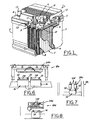
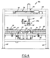
- FIGS. 3 ⁇ 5 illustrate the first machine 18a of the assembly line 10 which carries the intercell weld tool 24a for electrically connecting cells within the battery housing by welding together adjacent lead straps.
- the first machine 18a has a frame 40 with uprights 42 interconnected by upper cross rails 44 and lower cross rails 46.
- a conveyor bed 48 is carried by the lower cross rails 46 and has a pair of workstations 20, 22 defined in a central portion 50, and upstream 52 and downstream 54 portions adjacent the central portion 50.
- the upstream portion 52 of the conveyor bed 48 has a plurality of axially spaced, elongate rollers 56 carried by side plates 57 and extending generally perpendicular to the direction of travel of batteries 16 along the conveyor bed and driven for rotation in unison by a drive mechanism (not shown).
- the drive mechanism may comprise an electric motor which drives a sprocket and chain which meshes with a separate sprocket connected to each roller 56 to rotate the rollers 56 in unison and advance battery cases 16 disposed thereon.
- a diverter 58 has supports 60 extending in between two rollers 56 and a is reciprocated in a direction parallel to the rollers 56 to alternately guide batteries 16 from a single conveyor supply line 64 (FIG. 2) upstream of the first machine 18a to both workstations 20, 22 of the first machine 18a.
- Battery case guide rails 59 are disposed above and adjacent the end of the rollers and are laterally adjustable to accommodate cases of different widths.
- the central portion 50 of the conveyor bed 48 has a plurality of axially spaced apart and parallel belts 66 extending essentially perpendicular to the rollers 56 and parallel to the direction of travel of the conveyor.
- the belts 66 may be received around spaced apart shafts 67, 68 each extending parallel to the rollers 56 and driven in unison with the rollers 56 to advance a battery 16 at a surface speed substantially the same as that of the rotation of the rollers.
- each workstation 20, 22 disposed between the belts in each workstation.
- the lift rails 70 in each workstation are separately actuated to move in unison from a lowered position (FIG.
- batteries 16 may be alternately advanced by the central portion 50 of the conveyor bed 48 by raising one battery 16 off of the belts 66 and lowering the battery 16 in the other workstation onto the belts 66 so that it is advanced to the downstream portion 54 of the conveyor bed 48 by the belts 66. In this way, all of the belts 66 may be driven in unison with the batteries 16 on the different workstations 20, 22 alternately advanced.
- the downstream portion 54 of the conveyor bed 48 preferably has a plurality of rollers 76 carried by side plates 77 for co-rotation about an axis perpendicular to the direction of travel of batteries 16 in the assembly line 10.
- a fixed central rail 78 may be provided to guide batteries 16 from the first workstation 20 to the first conveyor 12 and batteries 16 from the second workstation 22 to the second conveyor 14:
- movable guides 82 may be reciprocated parallel to the rollers 76 to slidably move and align the batteries 16 from each workstation 20,22 to the downstream conveyor 80.
- a machine 18a-d may be used in an assembly line having a single conveyor between machines with the use of the diverter 58, which receives batteries from a single conveyor and distributes them to each workstation 20,22, and the guides 82 which receive batteries from each workstation 20,22 and direct them to a single downstream conveyor.
- the upstream and downstream portions 52, 54 of the conveyor bed 48 are preferably driven in unison so that as a battery is advanced from the central portion 50 to the downstream portion 54, a subsequent battery on the upstream portion 52 is advanced to the central portion 50.
- the upstream and downstream portions 52, 54 may be continuously driven with the supply conveyor 64 being selectively advanced when a battery 16 is needed in a workstation 20, 22 and with the diverter 58 operable to deliver batteries to each workstation 20,22 from the supply conveyor 64. Otherwise, sensors may be used to actuate separate controls for the upstream and downstream conveyor portions 52, 54 to selectively advance batteries 16 to and from the workstations with stops temporarily engaging batteries 16 not desired to be advanced.
- the batteries 16 may be provided to the machine 18a from two, separately controlled conveyor lines as shown in FIG. 2 for machines 18b, 18c and 18d.
- Each conveyor line would supply batteries to a separate workstation 20,22 and would be selectively, alternately advanced to alternately provide a new battery 16 to one and then the other of the workstations.
- each of the second 18b, third 18c and fourth machines 18d are configured in this manner to provide two separate conveyor lines 12-14 of batteries 16 each worked on by a single tool 24b-d at each machine 18b-d.
- the tool 24a-d at each machine 18a-d is carried by a shuttle 26 mounted by the upper cross rails 44 of the frame 40.
- Each shuttle 26 has a tool holder 90 slidably received on a pair of parallel and spaced apart support rails 92 which are connected at opposed ends to a pair of spaced apart and parallel guide rails 94 fixed to the frame 40 and extending essentially perpendicular to the support rails 92.
- a follower 96 connected to the tool holder 90 receives a ball screw 98 driven by a servo controlled electric motor 100, both carried by the support rails 92, to slidably move the tool holder 90 along the support rails 92.
- One or more followers 101 connected to the support rails 92 receive a ball screw 102 extending parallel to the guide rails 94 and selectively driven by another servo controlled motor 104 to slidably move the support rails 92 relative to the guide rails 94 and thereby move the tool 24a-d back and forth between the two workstations 20, 22.
- the tool holder 90 has a plate 106 spanning the support rails 92 with a plurality of linear slide bearings 108 disposed between the plate 106 and the support rails 92 to reduce friction between them.
- the ends of the support rails 92 carry linear bearings 110 to reduce friction between the support rails 92 and the guide rails 94.
- the work tool 24a-d can be moved along two perpendicular axes to move the tool in the direction of the conveyor movement and also perpendicular thereto between both workstations 20, 22.
- another servo controlled motor 112 is operably connected to an arm 114 which carries the tool 24a-d.
- the motor 112 is controlled to reciprocate the arm and move the tool 24a-d towards and away from the conveyor bed 48 to raise and lower the tool relative to the batteries 16 in the workstations 20,22.
- the tool 24a-d may be moved through three orthogonal or mutually perpendicular axes to dispose the tool 24a-d at substantially any location within both workstations 20, 22 of the machine 18a-d.
- the tool may not need to move in all three axes described above such as when the tool of a machine only performs work on one location of a battery.
- the support rails 92, ballscrew 98 and motor 100 can be eliminated because lateral movement or indexing of the tool within the workstations 20,22 would not be needed and the tool holder 90 can be slidably carried directly on the guide rails 94 and operably connected to ball screw 102 to move from one workstation to the other.
- the intercell weld tool 24a preferably has a pair of weld jaws 116, 118 slidably moved towards and away from each other to clamp and electrical resistance weld together straps disposed between adjacent cells 27 of a battery 16.
- the intercell weld tool 24a may be indexed to provide a plurality of welds in a single battery 16 and then moved by the shuttle 26 to provide similar welds to a battery 16 on the other workstation 20, 22.
- the weld jaws 116, 118 may be advanced and retracted by a pneumatic cylinder supplied with compressed air through hoses 120 communicating with an air supply through an solenoid actuated valve.
- the second machine 18b has a heat seal tool 24b carried by its shuttle 26 and operable to dispose a plastic lid or cover 28 onto the plastic case 30 of each battery housing 16 and to permanently connect and seal the cover 28 to the case 30 by applying heat to weld and seal together these plastic members.
- the heat seal tool 24b is carried by a shuttle 26 controlled in the same manner as the shuttle 26 for the intercell weld tool 24a such that it may be advanced and retracted relative to the battery housing 16 and transferred from one workstation to the other by its shuttle 26. Lateral movement within the workstations 20,22 may not be needed with the heat seal tool 24b and thus, its shuttle 26 may not need support rails 92, motor 100 or ball screw 98. Desirably, as best shown in FIG.
- two separate conveyor paths 12, 14 extend through the second machine 18b and are alternately advanced to alternately provide batteries 16 to the workstations 20, 22 of the second machine 18b.
- the second machine 18b may have a conveyor bed constructed as described with reference to the first machine 18a to distribute batteries from a single conveyor line to both workstations and/or to consolidate the batteries from both workstations to a single downstream conveyor line.
- the third machine 18c has a terminal post weld tool 24c carried by its shuttle 26.
- the terminal post weld tool 24c may comprise a pair of heads 124 each adapted to simultaneously weld a separate one of both terminal posts 32 extending through the cover 28 of a single battery housing to their surrounding bushings to electrically connect the terminals 32 and to provide a seal around them with the cover.
- the terminal weld tool 24c may comprise a single head indexed to weld the terminal posts 32 of the batteries 16 one after the other. In either arrangement, the terminal weld tool 24c may be advanced and retracted toward and away from the batteries 16 and also transferred from one workstation 20, 22 to the other by its shuttle 26.
- the third machine 18c may be used with two separate conveyor lines (as shown in FIG. 2) or may be configured to operate with a single conveyor upstream and/or downstream of the third machine 18c as described above with reference to the other machines.
- the fourth machine 18d may provide a leak test tool 24d.
- the leak test tool 24d has a plurality of outlets or nozzles each in communication with a compressed gas supply through a plurality of hoses 128.
- the nozzles inject the compressed gas into the wells of the various cells 27 of the battery housing 16 through openings in the cover 28 to determine if there are any leaks between the wells of the cells 27 of the battery 16 or otherwise in the battery housing.
- the leak test tool 24d may be advanced and retracted relative to the batteries 16 and transferred from one workstation 20, 22 to the other by its shuttle 26.
- the fourth machine 18d may also be used with two separate conveyors or may be configured to operate with a single conveyor upstream and/or downstream thereof as described with reference to the other machines.
- the entire assembly line 10 may be operated by one or more preprogrammed controls 36 so that the assembly line 10 is extremely flexible and may be readily automated and adapted to accommodate production runs of a wide variety of different battery styles and types.
- each of these operations may be performed at consecutive machines 18a-d along a conveyor assembly line 10 which can be substantially automated by one or more computer controls and various servo-controlled drive mechanisms.
- each machine 18a-d has at least a pair of workstations 20, 22 and the work tools 24a-d are carried by shuttles 26 which move the tools 24a-d between the workstations 20, 22.
- the tool 24a-d may be moved by the shuttle 26 to work on a battery 16 waiting in a second workstation 22.
- the battery 16 in the first workstation 20 which has already been worked on is advanced downstream of the first workstation 20 and a new battery 16 is advanced into the first workstation 20 so that it may be worked on by the tool 24a-d after the tool 24a-d completes its work on the battery 16 in the second workstation 22.
- the tool 24a-d is moved back to the first workstation 20 and the battery 16 in the second workstation 22 is advanced out of the second workstation 22 and a new battery 16 is moved into the second workstation 22.
- the batteries 16 on the workstations 20, 22 of the machine 18a-d are alternately advanced so that a new battery 16 is ready and waiting for the tool 24a-d in one workstation 20, 22 at all times.
- the tool 24a-d may be rapidly shuttled between the workstations 20, 22 to alternately work on batteries 16 in the workstations 20, 22.
Landscapes
- Engineering & Computer Science (AREA)
- Mechanical Engineering (AREA)
- Manufacturing & Machinery (AREA)
- Chemical & Material Sciences (AREA)
- Chemical Kinetics & Catalysis (AREA)
- Electrochemistry (AREA)
- General Chemical & Material Sciences (AREA)
- Sealing Battery Cases Or Jackets (AREA)
- Press Drives And Press Lines (AREA)
Abstract
Description
Claims (14)
- An apparatus having at least two workstations, comprising:a frame;a conveyor carried by the frame and having a first workstation and a second workstation and constructed and arranged to carry workpieces to and away from each workstation;a shuttle carried by the frame and adapted to be driven by at least one actuator for movement relative to the frame in at least one direction;a tool carried by the shuttle for movement between the first and second workstations and driven by an actuator for movement towards and away from the conveyor; anda control to dictate the operation of the conveyor, the shuttle and the tool so that after the tool performs work on a part in one workstation, the shuttle and tool are moved to perform work on a part in the other workstation and generally simultaneously, the workpiece in said one workstation is advanced to move the already worked on part out of the way and to bring a new part into position in said one workstation while the part in the other workstation is being worked on by the tool to maximize the number of workpieces the tool can work on in a given amount of time.
- The apparatus of claim 1 wherein the shuttle is driven by at least one servo-controlled motor.
- The apparatus of claim 1 which also comprises separate first and second conveyors carried at least in part by the frame, each constructed and arranged to move workpieces to and from one of the workstations and separately controlled to permit one conveyor to be advanced while the other conveyor is stopped.
- The apparatus of claim 1 wherein the shuttle comprises at least one guide rail carried by the frame, at least one support rail slidably carried by and extending generally perpendicular to the guide rail and a tool holder slidably carried by at least one support rail to permit movement of the tool holder in a first direction along the support rail and in a second direction perpendicular to the first direction along the guide rail with the support rail.
- The apparatus of claim 4 which also comprises a first actuator operably connected to the tool holder to drive the tool holder for movement relative to and along the support rail and a second actuator operably connected to at least one support rail to drive the support rail and tool holder for movement along the guide rail.
- The apparatus of claim 5 wherein two parallel support rails and two parallel guide rails are provided with the tool holder carried by each support rail and each support rail extending between and carried by each guide rail.
- The apparatus of claim 1 which also comprises a separator slidably carried by one of the conveyor and the frame for movement generally perpendicular to the direction of travel of workpieces on the conveyor bed and adapted to selectively guide workpieces from a single conveyor upstream of the apparatus to the first and second workstations.
- The apparatus of claim 1 which also comprises a pair of lifters, each carried by the frame adjacent a separate workstation and movable relative to the conveyor from a lowered position below the conveyor to a raised position to lift a workpiece from the conveyor and to hold the workpiece in position at a workstation.
- The apparatus of claim 1 which also comprises a guide slidably carried by one of the conveyor and the frame for movement generally perpendicular to the direction of travel of workpieces on the conveyor and adapted to selectively guide workpieces from each workstation to a single conveyor downstream of the apparatus.
- The apparatus of claim 1 wherein the tool is a welding gun adapted to provide at least one weld to each workpiece.
- The apparatus of claim 1 wherein the tool is a heat seal tool.
- The apparatus of claim 1 wherein the tool is a leak testing tool operably connected to a source of compressed gas.
- The apparatus of claim 1 wherein the tool is a terminal weld tool.
- An assembly line, comprising:a plurality of machines disposed one after another, each having a frame, at least a pair of workstations each constructed to receive a separate workpiece, a shuttle carried by the frame and movable relative to the frame, a tool carried by the shuttle for co-movement therewith to permit the tool to selectively work on workpieces in each workstation; anda conveyor for carrying workpieces to, from and between the machines and constructed and arranged to alternately provide a workpiece to each workstation so that after the tool of a machine has worked on a workpiece in one workstation, the tool may be moved by its shuttle to work on a workpiece in another workstation while the already worked on workpiece is advanced out of said one workstation and a subsequent workpiece is advanced into said one workstation so that the tool is not idle while the workpieces are advanced into their respective workstations.
Applications Claiming Priority (2)
| Application Number | Priority Date | Filing Date | Title |
|---|---|---|---|
| US298810 | 1999-04-23 | ||
| US09/298,810 US6279224B1 (en) | 1999-04-23 | 1999-04-23 | Battery assembly dual workstation |
Publications (2)
| Publication Number | Publication Date |
|---|---|
| EP1046459A2 true EP1046459A2 (en) | 2000-10-25 |
| EP1046459A3 EP1046459A3 (en) | 2003-08-27 |
Family
ID=23152091
Family Applications (1)
| Application Number | Title | Priority Date | Filing Date |
|---|---|---|---|
| EP00108550A Withdrawn EP1046459A3 (en) | 1999-04-23 | 2000-04-19 | Battery assembly dual workstation and method |
Country Status (2)
| Country | Link |
|---|---|
| US (1) | US6279224B1 (en) |
| EP (1) | EP1046459A3 (en) |
Cited By (5)
| Publication number | Priority date | Publication date | Assignee | Title |
|---|---|---|---|---|
| WO2007124774A1 (en) * | 2006-04-29 | 2007-11-08 | Trumpf Laser- Und Systemtechnik Gmbh | Mechanical assembly for moving work pieces and/or rests of work piece machining as well as mechanical assembly for machining work pieces |
| CN108673114A (en) * | 2018-07-06 | 2018-10-19 | 河北工业大学 | A kind of quick bead insertdevice of button cell pole shell |
| CN109926806A (en) * | 2019-01-14 | 2019-06-25 | 万向一二三股份公司 | A kind of the gas-permeable hose assembly equipment and method of battery modules |
| EP3778113A4 (en) * | 2018-03-29 | 2021-11-10 | Hirata Corporation | MACHINING SYSTEM AND MACHINING PROCESS |
| CN116021281A (en) * | 2023-02-24 | 2023-04-28 | 东台润田精密科技有限公司 | Photovoltaic board end connector automatic assembly equipment |
Families Citing this family (20)
| Publication number | Priority date | Publication date | Assignee | Title |
|---|---|---|---|---|
| US6512195B2 (en) * | 1999-12-20 | 2003-01-28 | Bryan W. Domschot | Modular welding machine |
| JP2003062727A (en) * | 2001-04-26 | 2003-03-05 | Fuji Photo Film Co Ltd | Assembly unit |
| US6763564B2 (en) * | 2002-04-04 | 2004-07-20 | Lakewood Engineering And Manufacturing Co. | Automated method and apparatus for driving fasteners into an electric fan assembly |
| CA2545461C (en) * | 2003-11-15 | 2012-11-13 | Tec-Option, Inc. | Modular welding equipment |
| US7637366B2 (en) * | 2004-06-04 | 2009-12-29 | Shuttleworth, Inc. | High speed diverter |
| US20060090332A1 (en) * | 2004-10-28 | 2006-05-04 | Vahid Taban | Contactless conveyor system for the production of smart cards |
| US8875361B2 (en) | 2008-05-21 | 2014-11-04 | Wirtz Manufacturing Co., Inc. | Reformed battery grids |
| US8424194B2 (en) * | 2010-04-21 | 2013-04-23 | Lg Chem, Ltd. | Apparatus for assembly of a press-fit modular work piece |
| US8336175B2 (en) * | 2010-08-11 | 2012-12-25 | Cheng Uei Precision Industry Co., Ltd. | Riveting press |
| US8739400B2 (en) | 2010-10-04 | 2014-06-03 | Lg Chem, Ltd. | Press assembly and method for bending electrical terminals of battery cells |
| CN103429382B (en) * | 2011-03-24 | 2016-02-24 | 村田机械株式会社 | Machine tool system |
| AT511065B1 (en) * | 2011-06-09 | 2012-09-15 | Rosendahl Masch Gmbh | METHOD AND DEVICE FOR CHECKING BATTERY PLATE PACKAGES |
| US9397331B2 (en) * | 2012-09-24 | 2016-07-19 | Wirtz Manufacturing Company, Inc. | Battery grid pasting machine and system |
| EP2894026B1 (en) * | 2014-01-13 | 2018-04-18 | HADI Offermann Maschinenbau GmbH | Welding machine for the production of batteries and method for the production of batteries by means of a welding machine |
| CN107871830A (en) * | 2017-12-05 | 2018-04-03 | 宁波必霸能源有限公司 | The two-way enclosed mechanism of button-shaped assembled battery |
| PL3740324T3 (en) * | 2018-01-17 | 2023-12-27 | Schmitt Prof. Möhlmann & Collegen Wirtschaftskanzlei -Insolvenzverwalter Aktiengesellschaft | Lubricant spray system and lubricant application method for treating inner surfaces of insertion and assembly aids in a packing station |
| DE102018110865B4 (en) * | 2018-05-07 | 2024-02-22 | Kuka Systems Gmbh | Battery cell preparation technology |
| CN110394615B (en) * | 2018-11-26 | 2021-08-13 | 沈阳工业大学 | A two-way automatic forming machine for heat sinks |
| KR102660448B1 (en) * | 2021-01-19 | 2024-04-23 | 주식회사 엘지에너지솔루션 | Assembly line system of stacked battery module |
| CN119029339B (en) * | 2024-10-29 | 2024-12-24 | 东莞市博森新能源有限公司 | Battery manufacturing equipment and process |
Family Cites Families (23)
| Publication number | Priority date | Publication date | Assignee | Title |
|---|---|---|---|---|
| DE1477580A1 (en) * | 1963-09-09 | 1970-01-08 | Mueller Dipl Ing Hellmut | Device for processing workpieces, e.g. Boring mill |
| US4013864A (en) * | 1968-08-16 | 1977-03-22 | Tiegel Manufacturing Company | Apparatus for fabricating through-the-wall battery connectors |
| US3848746A (en) * | 1969-08-08 | 1974-11-19 | Stork Amsterdam | Apparatus for diverting a row of cylindrical bodies alternately into two paths of travel |
| US3810554A (en) * | 1970-12-22 | 1974-05-14 | E London | Freezer unloading system for hamburger patties |
| US3908743A (en) * | 1974-01-21 | 1975-09-30 | Gould Inc | Positive displacement casting system employing shaped electrode for effecting cosmetically perfect bonds |
| US3955678A (en) * | 1974-08-09 | 1976-05-11 | American Chain & Cable Company, Inc. | Sorting system |
| US4440289A (en) * | 1981-12-21 | 1984-04-03 | Crown Zellerbach Corporation | Discrete article transport and consolidating system |
| US4509252A (en) * | 1982-07-06 | 1985-04-09 | Gnb Batteries Inc. | Method and apparatus for assembling battery components |
| US4596625A (en) * | 1983-12-13 | 1986-06-24 | Alvarez Oscar E | Heat sealing machine for joining a battery cover and battery casing |
| US4525923A (en) * | 1983-12-13 | 1985-07-02 | Alvarez Oscar E | Heat sealing machine for bonding battery covers and battery casings together |
| GB8700906D0 (en) * | 1987-01-16 | 1987-02-18 | Tbs Eng Cheltenham | Handling apparatus |
| JPH0197541A (en) * | 1987-10-07 | 1989-04-17 | Brother Ind Ltd | Machine Tools |
| JPH027929U (en) * | 1988-06-27 | 1990-01-18 | ||
| AU616588B2 (en) * | 1989-01-12 | 1991-10-31 | Dexion (Australia) Pty Limited | Diverter mechanism |
| AT398923B (en) * | 1989-04-04 | 1995-02-27 | Sticht Walter | MANUFACTURING SYSTEM WITH PARALLEL AND ADDITIONAL CONVEYOR |
| US5234473A (en) * | 1989-11-13 | 1993-08-10 | Daniell Battery Mfg. Co., Inc. | Heating platen transfer device |
| EP0615215B1 (en) * | 1993-03-11 | 1997-05-28 | De La Rue Giori S.A. | Value paper counting station, particularly banknotes in bundels |
| US5539975A (en) * | 1993-09-08 | 1996-07-30 | Allen-Bradley Company, Inc. | Control system and equipment configuration for a modular product assembly platform |
| EP0743135B1 (en) * | 1995-05-15 | 1999-07-14 | Elpatronic Ag | Process for bonding two workpieces |
| US5602328A (en) * | 1995-12-18 | 1997-02-11 | General Motors Corporation | Battery leak testing method |
| US5606114A (en) * | 1995-12-18 | 1997-02-25 | General Motors Corporation | Battery leak testing apparatus |
| EP0956607A4 (en) * | 1996-10-15 | 2000-12-06 | Farmer Mold & Machine Works | Apparatus for assembling a battery |
| US5979635A (en) * | 1997-10-22 | 1999-11-09 | Industrial Dynamics Co., Ltd. | Container diverter apparatus and method |
-
1999
- 1999-04-23 US US09/298,810 patent/US6279224B1/en not_active Expired - Fee Related
-
2000
- 2000-04-19 EP EP00108550A patent/EP1046459A3/en not_active Withdrawn
Cited By (10)
| Publication number | Priority date | Publication date | Assignee | Title |
|---|---|---|---|---|
| WO2007124774A1 (en) * | 2006-04-29 | 2007-11-08 | Trumpf Laser- Und Systemtechnik Gmbh | Mechanical assembly for moving work pieces and/or rests of work piece machining as well as mechanical assembly for machining work pieces |
| US7743910B2 (en) | 2006-04-29 | 2010-06-29 | Trumpf Laser- Und Systemtechnik Gmbh | Systems for processing workpieces and mechanical arrangements for moving workpieces and/or workpiece remnants |
| CN101466493B (en) * | 2006-04-29 | 2011-09-28 | 通快激光与系统工程有限公司 | Mechanisms for moving workpieces and/or machining residues remaining from machining workpieces and mechanisms for machining workpieces |
| JP4814373B2 (en) * | 2006-04-29 | 2011-11-16 | トルンプフ レーザー− ウント ジュステームテヒニク ゲゼルシャフト ミット ベシュレンクテル ハフツング | Device for moving workpiece and / or machining remainder and device for machining workpiece |
| EP3778113A4 (en) * | 2018-03-29 | 2021-11-10 | Hirata Corporation | MACHINING SYSTEM AND MACHINING PROCESS |
| US11351639B2 (en) | 2018-03-29 | 2022-06-07 | Hirata Corporation | Working system and work method |
| CN108673114A (en) * | 2018-07-06 | 2018-10-19 | 河北工业大学 | A kind of quick bead insertdevice of button cell pole shell |
| CN108673114B (en) * | 2018-07-06 | 2023-06-16 | 河北工业大学 | A button-type battery pole shell fast buckle ring device |
| CN109926806A (en) * | 2019-01-14 | 2019-06-25 | 万向一二三股份公司 | A kind of the gas-permeable hose assembly equipment and method of battery modules |
| CN116021281A (en) * | 2023-02-24 | 2023-04-28 | 东台润田精密科技有限公司 | Photovoltaic board end connector automatic assembly equipment |
Also Published As
| Publication number | Publication date |
|---|---|
| EP1046459A3 (en) | 2003-08-27 |
| US6279224B1 (en) | 2001-08-28 |
Similar Documents
| Publication | Publication Date | Title |
|---|---|---|
| US6279224B1 (en) | Battery assembly dual workstation | |
| CN110640407B (en) | Automatic welding and assembling production line for automotive aluminum alloy box | |
| CN112331899B (en) | Power battery module production line | |
| CN105965160B (en) | A kind of battery cover board welding equipment | |
| CN111097869A (en) | Riveting equipment for electric vehicle relay and riveting method thereof | |
| CN112331900B (en) | A battery module production line | |
| CN205904579U (en) | Battery apron welding equipment | |
| US20030115746A1 (en) | Side panel assembly line | |
| CN113458749B (en) | Automatic assembly production line for touch screen | |
| CN114203591B (en) | Automatic packaging equipment for chip packaging | |
| KR101859877B1 (en) | Automatic clip mounting machine for Automobile | |
| CN109719412B (en) | Side wall welding production system | |
| CN110893544A (en) | A small charger automatic assembly and detection system | |
| CN103490096A (en) | Automatic battery assembly system | |
| CN109551250B (en) | Storage battery power interface welding equipment | |
| CN107498166B (en) | Chain saw guide plate dislocation spot-welding equipment | |
| CN111628374A (en) | Row inserts welding equipment | |
| CN110293399B (en) | Assembly production line for engine galvanic pile and hydrogen pipe assembly | |
| CN212162301U (en) | Row inserts welding equipment | |
| US20020100158A1 (en) | Method and system for efficient assembly of automotive components | |
| CN215830901U (en) | Automatic assembly production line for touch screen | |
| CN113084533B (en) | Double-root synchronous corner penetrating machine | |
| CN106077926A (en) | A kind of system of batch welding battery electrode | |
| CN206464691U (en) | A kind of stitch welding machine | |
| CN219286477U (en) | Battery cell interval adjusting mechanism and battery assembly production line |
Legal Events
| Date | Code | Title | Description |
|---|---|---|---|
| PUAI | Public reference made under article 153(3) epc to a published international application that has entered the european phase |
Free format text: ORIGINAL CODE: 0009012 |
|
| AK | Designated contracting states |
Kind code of ref document: A2 Designated state(s): AT BE CH CY DE DK ES FI FR GB GR IE IT LI LU MC NL PT SE |
|
| AX | Request for extension of the european patent |
Free format text: AL;LT;LV;MK;RO;SI |
|
| RIN1 | Information on inventor provided before grant (corrected) |
Inventor name: VAN VUREN, STEPHANUS PETRUS JANSE Inventor name: WIRTZ, JOHN O. |
|
| PUAL | Search report despatched |
Free format text: ORIGINAL CODE: 0009013 |
|
| AK | Designated contracting states |
Designated state(s): AT BE CH CY DE DK ES FI FR GB GR IE IT LI LU MC NL PT SE |
|
| AX | Request for extension of the european patent |
Extension state: AL LT LV MK RO SI |
|
| RIC1 | Information provided on ipc code assigned before grant |
Ipc: 7B 23Q 1/66 B Ipc: 7B 23P 21/00 B Ipc: 7B 23P 19/04 B Ipc: 7B 23Q 41/06 B Ipc: 7B 23Q 41/02 B Ipc: 7B 23Q 39/00 B Ipc: 7B 23Q 7/14 A |
|
| 17P | Request for examination filed |
Effective date: 20040212 |
|
| AKX | Designation fees paid |
Designated state(s): DE FR GB IT |
|
| 17Q | First examination report despatched |
Effective date: 20050202 |
|
| STAA | Information on the status of an ep patent application or granted ep patent |
Free format text: STATUS: THE APPLICATION IS DEEMED TO BE WITHDRAWN |
|
| 18D | Application deemed to be withdrawn |
Effective date: 20050614 |