EP1046404A2 - Sharps destroyer - Google Patents
Sharps destroyer Download PDFInfo
- Publication number
- EP1046404A2 EP1046404A2 EP20000201394 EP00201394A EP1046404A2 EP 1046404 A2 EP1046404 A2 EP 1046404A2 EP 20000201394 EP20000201394 EP 20000201394 EP 00201394 A EP00201394 A EP 00201394A EP 1046404 A2 EP1046404 A2 EP 1046404A2
- Authority
- EP
- European Patent Office
- Prior art keywords
- electrodes
- sharps
- metallic
- destroying
- electrode device
- Prior art date
- Legal status (The legal status is an assumption and is not a legal conclusion. Google has not performed a legal analysis and makes no representation as to the accuracy of the status listed.)
- Withdrawn
Links
Images

Classifications
-
- A—HUMAN NECESSITIES
- A61—MEDICAL OR VETERINARY SCIENCE; HYGIENE
- A61M—DEVICES FOR INTRODUCING MEDIA INTO, OR ONTO, THE BODY; DEVICES FOR TRANSDUCING BODY MEDIA OR FOR TAKING MEDIA FROM THE BODY; DEVICES FOR PRODUCING OR ENDING SLEEP OR STUPOR
- A61M5/00—Devices for bringing media into the body in a subcutaneous, intra-vascular or intramuscular way; Accessories therefor, e.g. filling or cleaning devices, arm-rests
- A61M5/178—Syringes
- A61M5/31—Details
- A61M5/32—Needles; Details of needles pertaining to their connection with syringe or hub; Accessories for bringing the needle into, or holding the needle on, the body; Devices for protection of needles
- A61M5/3205—Apparatus for removing or disposing of used needles or syringes, e.g. containers; Means for protection against accidental injuries from used needles
- A61M5/3278—Apparatus for destroying used needles or syringes
- A61M2005/3283—Apparatus for destroying used needles or syringes using electric current between electrodes
Definitions
- the present invention relates to apparatus for destroying needles in particular hypodermic needles.
- the object of the present invention is to provide an improved device for destroying needles.
- an electrode device for destroying metallic sharps comprising
- the non-metallic material is included on an underside of an overhanging one of the electrodes.
- the non-metallic material will be carbon, and the electrodes will be made of or include copper.
- the electrodes may be made from heat hardened copper and coated on at least one surface with graphite having a thickness of approximately 5 microns ( ⁇ m).
- At least one electrode will have a surface at the gap which is made from a sintered mixture including copper and carbon.
- the quantity of copper in the sintered mixture is approximately 82-85% and the quantity of carbon is approximately 12%, and the other material in the sintered mixture comprises binding agents, tin and zinc.
- equipment for destroying metallic sharps characterised in that the equipment comprises a body and a disposable head, the body and the head having co-operating mating parts and contacts for mechanical and electrical connection;
- the charging circuit is adapted to charge from a car battery or any 12v source.
- the charging circuit includes a switch mode device for charging the batteries, and monitoring means for monitoring the charge level in batteries. More particularly the monitoring means is a DS 1223.
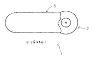
- the device 1 is divided into two parts; a head 2 and a body 3, designed in use to be connected to each other.
- the head 2 is domed 21 having an aperture 22 in its top.
- the head 2 has a flat underside 23 with an rectangular extension 24 along its length.
- the body 3 is rectangular in shape having extensions 31 at one end enabling the extension 24 of the head 2 to fit between them.
- the head 2 and body 3 have complimentarily shaped electrical connections 25, 32.
- the body 3 houses a charging circuit.
- the circuit is designed to charge from a car battery or any 12 v source, over a period of 4 hours. Each charge is designed to destroy 30 needles.
- the charging circuit includes an indicator to show that the battery holds enough power to destroy a needle.
- the charging circuit includes a standard switch mode device, or DC to DC switching controller for charging standard 4v batteries.
- the switch mode device allows maximum power to be fed to the batteries without high heat loss.
- the charging circuit also includes means for monitoring the charge level of the batteries.
- a DS 1223 is used to monitor the voltage level.
- This standard device is usually used in a low-voltage monitoring device, where it monitors the voltage, and if it falls below a specified level, the device will switch the monitor into re-start mode. In the present invention the device is used to monitor the charge level in the batteries. Upon depression of a test switch the device is connected across the batteries. If the charge level is above a minimum, a green led is activated, while if the charge level is on or below the minimum a red led is activated indicating that the batteries need recharging. Approximately thirty needles can be destroyed on a single charge.
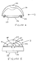
- the head 2 holds a pair of electrodes 40, directly beneath the aperture 22.
- the electrodes are shaped so that a needle or the like pushed into the aperture will contact both electrodes.
- One of the electrodes, 41 is approximately domed in shape, to allow a needle a large surface area to contact.
- the other electrode 42 is shaped rather like an anvil, with the extension 43 above at least a part of the domed lower electrode 41.
- Each electrode is made from heat hardened copper and coated in a thin layer of graphite, of the order of 5 microns thick. While it has been found that it is only necessary to coat the underside 44 of the upper electrode in graphite, in practice, the whole electrode is usually graphite coated. For maximising the life of the electrodes both are graphite coated. Alternatively one or both the electrodes are made from a sintered mixture of copper and graphite. A typical mixture would contain approximately 82-85% copper and approximately 12% graphite, together with small quantities of a binding agent, tin and zinc.
- Electrodes made purely of copper become pitted as small fragments of the molten needle adheres to its surface, resulting in arcing and/or bridging to the other electrode.
- the presence of carbon in the electrodes, either as a coating or integral part of the electrode greatly reduces this. It is particularly important to ensure that the lower surface 43 of the upper electrode 42 includes carbon as this is particularly prone to damage due to adherence of debris produced by spitting as the needle comes into contact with the lower electrode. Any debris build up on this section of the electrode reduces the distance between the electrodes, and hence the likelihood of arcing or bridging.
- the use of copper in the electrodes allows a high current to be used, of the order of 400 amps. Copper also has a high heat capacity, resulting in low impedance in the electrodes when a current is passed through them.
- the use of copper insures that the heat capacity of the electrodes is higher than that of the needles preventing over heating of the electrodes. Thus the current flowing through the needle melts and burns it, but does not adversely effect the electrodes.
- the electrodes are composed of a mixture of carbon and copper, the amount of the carbon is critical to ensure that these electrical properties are not compromised, while the presence of the carbon prevents damage to the electrodes during the destruction of the needles.
- the electrodes are shaped so that a needle introduced into the aperture can contact both electrodes.
- the shape of the electrodes is also important for allowing the debris from the melting and burning to fall away into the compartment.
- the positioning of the electrodes ensures that the device operates efficiently. If the separation is too large, then a larger current would be necessary to overcome the resistance in the needle and thick needles may not be destroyed. On the other hand if the separation is too small, the debris from the melting of the needles can cause bridging between the electrodes leading to discharge from the battery.
- the separation between the needles will be between 1-5 and 2.0 mm in either direction.
Landscapes
- Health & Medical Sciences (AREA)
- Engineering & Computer Science (AREA)
- Heart & Thoracic Surgery (AREA)
- Vascular Medicine (AREA)
- Anesthesiology (AREA)
- Biomedical Technology (AREA)
- Environmental & Geological Engineering (AREA)
- Hematology (AREA)
- Life Sciences & Earth Sciences (AREA)
- Animal Behavior & Ethology (AREA)
- General Health & Medical Sciences (AREA)
- Public Health (AREA)
- Veterinary Medicine (AREA)
- Secondary Cells (AREA)
- Battery Electrode And Active Subsutance (AREA)
Abstract
Description
- The present invention relates to apparatus for destroying needles in particular hypodermic needles.
- The disposal of needles and the like causes a serious problem. Frequently the needle contains traces of blood products or other hazardous materials. Such needles must be disposed of in such a way that there is no danger to the disposer by way of stabbing by the needle. Thus these needles cannot be placed in a standard plastic refuse sack as the needles will pierce the side of the sack and can injure a handler. One method commonly used is to provide a separate box for these needles. The boxes are usually made of stiffened plastic material and have a small aperture in their top through the needle can be pushed. However, although this reduces the likelihood of injury to another person, it does not destroy any toxic residue which may be present on the needle. Furthermore, for health workers who may have to travel to see their patients it is not very convenient nor safe to carry around a box containing the needles used on previous patients.
- Another method of destroying these needles is to incinerate them. This destroys the toxic residue on the needle as well as the needle itself. It is known to provide incinerators as portable hand held devices. The needles are pushed through a small aperture in the device onto a pair of electrodes held within the device. A voltage is held across the electrodes which on contact with the needle passes a current through the needle high enough to melt and at least partially burn the needle. However, this type of device has not been very reliable as during the destruction of the needle, small fragments of the molten or partially destroyed needle may adhere to the electrodes causing arcing and bridging of the electrodes. This wastes energy stored in batteries, and causes pitting of the electrodes, wearing them out very rapidly.
- The object of the present invention is to provide an improved device for destroying needles.
- According to the invention there is provided an electrode device for destroying metallic sharps, the device comprising
- a pair of spaced electrodes; and
- means for passing an electrical current therebetween for destruction of a metallic sharp by ohmic heating when the sharp extends into a gap between the electrodes
- Preferably the non-metallic material is included on an underside of an overhanging one of the electrodes. Normally the non-metallic material will be carbon, and the electrodes will be made of or include copper.
- The electrodes may be made from heat hardened copper and coated on at least one surface with graphite having a thickness of approximately 5 microns (µm).
- However, normally at least one electrode will have a surface at the gap which is made from a sintered mixture including copper and carbon. Typically the quantity of copper in the sintered mixture is approximately 82-85% and the quantity of carbon is approximately 12%, and the other material in the sintered mixture comprises binding agents, tin and zinc.
- According to a second aspect of the invention there is provided equipment for destroying metallic sharps, characterised in that the equipment comprises a body and a disposable head, the body and the head having co-operating mating parts and contacts for mechanical and electrical connection;
- the body having a casing containing
- electrical current supply means including batteries and a charging circuit therefor;
- the disposable head having a casing containing
- an electrode device of the first aspect of the invention;
- an aperture in the casing above the electrodes, for access of a metallic sharp to the electrodes.
- Preferably the charging circuit is adapted to charge from a car battery or any 12v source.
- Preferably the charging circuit includes a switch mode device for charging the batteries, and monitoring means for monitoring the charge level in batteries. More particularly the monitoring means is a DS 1223.
- To help understanding of the invention, a specific embodiment thereof will now be described by way of example and with reference to the accompanying drawings in which:-
- Figure 1 is a top view of the device;
- Figure 2 is a front perspective view of the body;
- Figure 3 is a front perspective view of the disposable head;
- Figure 4 is a front view of the head; and
- Figure 5 is a side view of the electrodes;
-
- Referring to Figure 1, the device 1 is divided into two parts; a
head 2 and abody 3, designed in use to be connected to each other. Thehead 2 is domed 21 having anaperture 22 in its top. Thehead 2 has aflat underside 23 with anrectangular extension 24 along its length. Thebody 3 is rectangular inshape having extensions 31 at one end enabling theextension 24 of thehead 2 to fit between them. Thehead 2 andbody 3 have complimentarily shapedelectrical connections - Referring to Figure 3, the
body 3 houses a charging circuit. The circuit is designed to charge from a car battery or any 12 v source, over a period of 4 hours. Each charge is designed to destroy 30 needles. The charging circuit includes an indicator to show that the battery holds enough power to destroy a needle. - The charging circuit includes a standard switch mode device, or DC to DC switching controller for charging standard 4v batteries. The switch mode device allows maximum power to be fed to the batteries without high heat loss. The charging circuit also includes means for monitoring the charge level of the batteries. A DS 1223 is used to monitor the voltage level. This standard device is usually used in a low-voltage monitoring device, where it monitors the voltage, and if it falls below a specified level, the device will switch the monitor into re-start mode. In the present invention the device is used to monitor the charge level in the batteries. Upon depression of a test switch the device is connected across the batteries. If the charge level is above a minimum, a green led is activated, while if the charge level is on or below the minimum a red led is activated indicating that the batteries need recharging. Approximately thirty needles can be destroyed on a single charge.
- Referring to Figure 5, the
head 2 holds a pair ofelectrodes 40, directly beneath theaperture 22. The electrodes are shaped so that a needle or the like pushed into the aperture will contact both electrodes. One of the electrodes, 41 is approximately domed in shape, to allow a needle a large surface area to contact. Theother electrode 42 is shaped rather like an anvil, with the extension 43 above at least a part of the domed lower electrode 41. Thus a needled inserted through theaperture 22 in thedomed head 21, with contact the edge of the extension 43 of the anvil shapedelectrode 42, and the domed electrode 41, resulting, when the device is switched on, in a current passing through the needle. - Each electrode is made from heat hardened copper and coated in a thin layer of graphite, of the order of 5 microns thick. While it has been found that it is only necessary to coat the underside 44 of the upper electrode in graphite, in practice, the whole electrode is usually graphite coated. For maximising the life of the electrodes both are graphite coated. Alternatively one or both the electrodes are made from a sintered mixture of copper and graphite. A typical mixture would contain approximately 82-85% copper and approximately 12% graphite, together with small quantities of a binding agent, tin and zinc.
- Electrodes made purely of copper become pitted as small fragments of the molten needle adheres to its surface, resulting in arcing and/or bridging to the other electrode. However the presence of carbon in the electrodes, either as a coating or integral part of the electrode greatly reduces this. It is particularly important to ensure that the lower surface 43 of the
upper electrode 42 includes carbon as this is particularly prone to damage due to adherence of debris produced by spitting as the needle comes into contact with the lower electrode. Any debris build up on this section of the electrode reduces the distance between the electrodes, and hence the likelihood of arcing or bridging. With the addition of carbon as coating or constituent of the electrode, as the molten swarf from the needle moves between the electrodes it continues to melt without arcing and then falls away from the electrodes. The use of copper in the electrodes allows a high current to be used, of the order of 400 amps. Copper also has a high heat capacity, resulting in low impedance in the electrodes when a current is passed through them. The use of copper insures that the heat capacity of the electrodes is higher than that of the needles preventing over heating of the electrodes. Thus the current flowing through the needle melts and burns it, but does not adversely effect the electrodes. If the electrodes are composed of a mixture of carbon and copper, the amount of the carbon is critical to ensure that these electrical properties are not compromised, while the presence of the carbon prevents damage to the electrodes during the destruction of the needles. - The electrodes are shaped so that a needle introduced into the aperture can contact both electrodes. The shape of the electrodes is also important for allowing the debris from the melting and burning to fall away into the compartment. The positioning of the electrodes ensures that the device operates efficiently. If the separation is too large, then a larger current would be necessary to overcome the resistance in the needle and thick needles may not be destroyed. On the other hand if the separation is too small, the debris from the melting of the needles can cause bridging between the electrodes leading to discharge from the battery. Typically the separation between the needles will be between 1-5 and 2.0 mm in either direction.
Claims (13)
- An electrode device (2) for destroying metallic sharps, the device comprisingcharacterised in that at least one of the electrodes (42) has a surface (44) at the gap which includes non-metallic material for discouraging adhesion of molten sharps debris thereto.a pair of spaced electrodes (41, 42); andmeans (25) for passing an electrical current therebetween for destruction of a metallic sharp by ohmic heating when the sharp extends into a gap between the electrodes
- An electrode device (2) for destroying metallic sharps as claimed in claim 1, characterised in that the non-metallic material is included on an underside (44) of an overhanging one of the electrodes (42).
- An electrode device (2) for destroying metallic sharps as claimed in claim 1 or claim 2, characterised in that the non-metallic material is carbon.
- An electrode device (2) for destroying metallic sharps as claimed in claim 1, claim 2 or claim 3, characterised in that the electrodes (41, 42) are made of copper or include copper.
- An electrode device (2) for destroying metallic sharps as claimed in any one of claims 1 to 4, characterised in that the electrodes (41, 42) are made from heat hardened copper and at least one surface (44) of which is coated in graphite.
- An electrode device (2) for destroying metallic sharps as claimed in claim 5, characterised in that the thickness of the graphite coating is of the order of 5 microns (µm).
- An electrode device (2) for destroying metallic sharps as claimed in any one of claims 1 to 4, characterised in that at least one electrode (42) has a surface (44) at the gap which is made from a sintered mixture including copper and carbon.
- An electrode device (2) for destroying metallic sharps as claimed in claim 6, characterised in that the quantity of copper in the electrode (42) is approximately 82-85% and the quantity of carbon is approximately 12%.
- An electrode device (2) for destroying metallic sharps as claimed in claim 8 characterised in that that the other material in the electrode (42) comprises binding agents, tin and zinc.
- Equipment for destroying metallic sharps (1), characterised in that the equipment comprises a body (3) and a disposable head (2), the body (3) and the head (2) having co-operating mating parts (23, 31) and contacts (25, 32) for mechanical and electrical connection;the body (3) having a casing containingelectrical current supply means including batteries and a charging circuit therefor;disposable head (2) having a casing (21) containingan electrode device (2) as claimed in any preceding claim.an aperture (22) in the casing (21) above the electrodes (41, 42), for access of a metallic sharp to the electrodes.
- Equipment for destroying metallic sharps (1) as claimed in claim 10, characterised in that the charging circuit is adapted to charge from a car battery or any 12v source.
- Equipment for destroying metallic sharps (1) as claimed in claim 10 or claim 11, characterised in that the charging circuit includes a switch mode device for charging the batteries, and monitoring means for monitoring the charge level in batteries.
- Equipment for destroying metallic sharps (1) as claimed in claim 12, characterised in that the monitoring means is a DS 1223.
Applications Claiming Priority (2)
| Application Number | Priority Date | Filing Date | Title |
|---|---|---|---|
| GB9909087 | 1999-04-21 | ||
| GBGB9909087.0A GB9909087D0 (en) | 1999-04-21 | 1999-04-21 | Sharps destroyer |
Publications (2)
| Publication Number | Publication Date |
|---|---|
| EP1046404A2 true EP1046404A2 (en) | 2000-10-25 |
| EP1046404A3 EP1046404A3 (en) | 2002-06-05 |
Family
ID=10851931
Family Applications (1)
| Application Number | Title | Priority Date | Filing Date |
|---|---|---|---|
| EP00201394A Withdrawn EP1046404A3 (en) | 1999-04-21 | 2000-04-19 | Sharps destroyer |
Country Status (3)
| Country | Link |
|---|---|
| EP (1) | EP1046404A3 (en) |
| CA (1) | CA2306316A1 (en) |
| GB (1) | GB9909087D0 (en) |
Cited By (1)
| Publication number | Priority date | Publication date | Assignee | Title |
|---|---|---|---|---|
| GB2530102A (en) * | 2014-09-15 | 2016-03-16 | Grace Sheedy | Lightweight, portable, handheld, rechargeable, needle safety incineration device and charging dock |
Citations (4)
| Publication number | Priority date | Publication date | Assignee | Title |
|---|---|---|---|---|
| EP0262686A2 (en) * | 1986-10-02 | 1988-04-06 | BRANDENSTEIN, Erwin | Device for disinfecting or glowing injection needles |
| WO1992019291A1 (en) * | 1991-05-07 | 1992-11-12 | Malcolm Campbell Mcintyre | Apparatus and method for the destruction of sharps |
| US5365029A (en) * | 1993-07-15 | 1994-11-15 | Esu Makku Co., Ltd. | Device for disposing injection needles |
| GB2297230A (en) * | 1994-12-12 | 1996-07-24 | Modular Systems & Dev Co Ltd | Apparatus for and method of destroying syringe needles |
-
1999
- 1999-04-21 GB GBGB9909087.0A patent/GB9909087D0/en not_active Ceased
-
2000
- 2000-04-19 EP EP00201394A patent/EP1046404A3/en not_active Withdrawn
- 2000-04-20 CA CA 2306316 patent/CA2306316A1/en not_active Abandoned
Patent Citations (4)
| Publication number | Priority date | Publication date | Assignee | Title |
|---|---|---|---|---|
| EP0262686A2 (en) * | 1986-10-02 | 1988-04-06 | BRANDENSTEIN, Erwin | Device for disinfecting or glowing injection needles |
| WO1992019291A1 (en) * | 1991-05-07 | 1992-11-12 | Malcolm Campbell Mcintyre | Apparatus and method for the destruction of sharps |
| US5365029A (en) * | 1993-07-15 | 1994-11-15 | Esu Makku Co., Ltd. | Device for disposing injection needles |
| GB2297230A (en) * | 1994-12-12 | 1996-07-24 | Modular Systems & Dev Co Ltd | Apparatus for and method of destroying syringe needles |
Cited By (1)
| Publication number | Priority date | Publication date | Assignee | Title |
|---|---|---|---|---|
| GB2530102A (en) * | 2014-09-15 | 2016-03-16 | Grace Sheedy | Lightweight, portable, handheld, rechargeable, needle safety incineration device and charging dock |
Also Published As
| Publication number | Publication date |
|---|---|
| GB9909087D0 (en) | 1999-06-16 |
| EP1046404A3 (en) | 2002-06-05 |
| CA2306316A1 (en) | 2000-10-21 |
Similar Documents
| Publication | Publication Date | Title |
|---|---|---|
| EP0714336B1 (en) | Electrical apparatus for destroying hypodermic syringe needles | |
| US5076178A (en) | Syringe needle destruction method and apparatus | |
| US5282428A (en) | Medical needle incinerator and sealer | |
| US5336862A (en) | Apparatus for destroying syringe-type needles by electrical current | |
| GB2211420A (en) | Improvements relating to the destruction of hypodermic needles | |
| US6545242B1 (en) | Apparatus and method for removing a needle from a syringe | |
| CA2170179A1 (en) | Ion generator in connect/disconnect of plastic tubes | |
| US5868709A (en) | Portable modular apparatus and method for destroying medical needles | |
| EP1046404A2 (en) | Sharps destroyer | |
| US5391849A (en) | Electrical disposal apparatus of used injection syringe | |
| AU5404096A (en) | Apparatus for disposing of hypodermic needles | |
| US5540416A (en) | Injection needle melting/destroying device | |
| CA2112267A1 (en) | Incinerator, particularly for used medical needles | |
| WO1998004305A1 (en) | Portable hand-held device for incinerating needles | |
| WO1992019291A1 (en) | Apparatus and method for the destruction of sharps | |
| GB2268407A (en) | Device for the disposal of hypodermic needles | |
| US20020074315A1 (en) | Needle incinerator | |
| EP0703769B1 (en) | Syringe needle destruction method and apparatus | |
| US9327085B2 (en) | Needle disabling device using electric current | |
| US6376792B1 (en) | Method and apparatus for individual destruction of syringe needles by melting under the effect of electric current | |
| GB2297230A (en) | Apparatus for and method of destroying syringe needles | |
| JP2000507851A (en) | Device for destroying objects such as needles | |
| JPH0258937B2 (en) | ||
| GB2300339A (en) | Apparatus for disposing of hypodermic needles using electrodes in a disposable cartridge | |
| EP1305130A1 (en) | Method and apparatus for destroying needles |
Legal Events
| Date | Code | Title | Description |
|---|---|---|---|
| PUAI | Public reference made under article 153(3) epc to a published international application that has entered the european phase |
Free format text: ORIGINAL CODE: 0009012 |
|
| AK | Designated contracting states |
Kind code of ref document: A2 Designated state(s): AT BE CH CY DE DK ES FI FR GB GR IE IT LI LU MC NL PT SE |
|
| AX | Request for extension of the european patent |
Free format text: AL;LT;LV;MK;RO;SI |
|
| PUAL | Search report despatched |
Free format text: ORIGINAL CODE: 0009013 |
|
| AK | Designated contracting states |
Kind code of ref document: A3 Designated state(s): AT BE CH CY DE DK ES FI FR GB GR IE IT LI LU MC NL PT SE |
|
| AX | Request for extension of the european patent |
Free format text: AL;LT;LV;MK;RO;SI |
|
| 17P | Request for examination filed |
Effective date: 20021202 |
|
| AKX | Designation fees paid |
Designated state(s): AT BE CH CY DE DK ES FI FR GB GR IE IT LI LU MC NL PT SE |
|
| STAA | Information on the status of an ep patent application or granted ep patent |
Free format text: STATUS: THE APPLICATION IS DEEMED TO BE WITHDRAWN |
|
| 18D | Application deemed to be withdrawn |
Effective date: 20021101 |