EP1046047B1 - Magnetoresistive sensor element with selective magnetization direction of the bias layer - Google Patents
Magnetoresistive sensor element with selective magnetization direction of the bias layer Download PDFInfo
- Publication number
- EP1046047B1 EP1046047B1 EP99936399A EP99936399A EP1046047B1 EP 1046047 B1 EP1046047 B1 EP 1046047B1 EP 99936399 A EP99936399 A EP 99936399A EP 99936399 A EP99936399 A EP 99936399A EP 1046047 B1 EP1046047 B1 EP 1046047B1
- Authority
- EP
- European Patent Office
- Prior art keywords
- layer
- sensor element
- magnetization direction
- sensor
- magnetic field
- Prior art date
- Legal status (The legal status is an assumption and is not a legal conclusion. Google has not performed a legal analysis and makes no representation as to the accuracy of the status listed.)
- Expired - Lifetime
Links
- 230000005415 magnetization Effects 0.000 title claims abstract description 46
- 230000005291 magnetic effect Effects 0.000 claims abstract description 42
- 239000004020 conductor Substances 0.000 claims description 11
- 239000000696 magnetic material Substances 0.000 claims description 6
- 238000000034 method Methods 0.000 claims description 6
- 239000012212 insulator Substances 0.000 claims description 3
- 238000001514 detection method Methods 0.000 description 9
- 230000001419 dependent effect Effects 0.000 description 5
- 230000000694 effects Effects 0.000 description 5
- 230000006978 adaptation Effects 0.000 description 2
- 230000005290 antiferromagnetic effect Effects 0.000 description 2
- 239000000463 material Substances 0.000 description 2
- 238000005259 measurement Methods 0.000 description 2
- 239000000758 substrate Substances 0.000 description 2
- 239000010409 thin film Substances 0.000 description 2
- 238000002485 combustion reaction Methods 0.000 description 1
- 238000010276 construction Methods 0.000 description 1
- 230000008878 coupling Effects 0.000 description 1
- 238000010168 coupling process Methods 0.000 description 1
- 238000005859 coupling reaction Methods 0.000 description 1
- 230000006378 damage Effects 0.000 description 1
- 230000006735 deficit Effects 0.000 description 1
- 238000010586 diagram Methods 0.000 description 1
- 230000005389 magnetism Effects 0.000 description 1
- 230000035945 sensitivity Effects 0.000 description 1
Images


Classifications
-
- G—PHYSICS
- G01—MEASURING; TESTING
- G01D—MEASURING NOT SPECIALLY ADAPTED FOR A SPECIFIC VARIABLE; ARRANGEMENTS FOR MEASURING TWO OR MORE VARIABLES NOT COVERED IN A SINGLE OTHER SUBCLASS; TARIFF METERING APPARATUS; MEASURING OR TESTING NOT OTHERWISE PROVIDED FOR
- G01D5/00—Mechanical means for transferring the output of a sensing member; Means for converting the output of a sensing member to another variable where the form or nature of the sensing member does not constrain the means for converting; Transducers not specially adapted for a specific variable
- G01D5/12—Mechanical means for transferring the output of a sensing member; Means for converting the output of a sensing member to another variable where the form or nature of the sensing member does not constrain the means for converting; Transducers not specially adapted for a specific variable using electric or magnetic means
- G01D5/14—Mechanical means for transferring the output of a sensing member; Means for converting the output of a sensing member to another variable where the form or nature of the sensing member does not constrain the means for converting; Transducers not specially adapted for a specific variable using electric or magnetic means influencing the magnitude of a current or voltage
- G01D5/142—Mechanical means for transferring the output of a sensing member; Means for converting the output of a sensing member to another variable where the form or nature of the sensing member does not constrain the means for converting; Transducers not specially adapted for a specific variable using electric or magnetic means influencing the magnitude of a current or voltage using Hall-effect devices
- G01D5/145—Mechanical means for transferring the output of a sensing member; Means for converting the output of a sensing member to another variable where the form or nature of the sensing member does not constrain the means for converting; Transducers not specially adapted for a specific variable using electric or magnetic means influencing the magnitude of a current or voltage using Hall-effect devices influenced by the relative movement between the Hall device and magnetic fields
-
- B—PERFORMING OPERATIONS; TRANSPORTING
- B82—NANOTECHNOLOGY
- B82Y—SPECIFIC USES OR APPLICATIONS OF NANOSTRUCTURES; MEASUREMENT OR ANALYSIS OF NANOSTRUCTURES; MANUFACTURE OR TREATMENT OF NANOSTRUCTURES
- B82Y25/00—Nanomagnetism, e.g. magnetoimpedance, anisotropic magnetoresistance, giant magnetoresistance or tunneling magnetoresistance
-
- G—PHYSICS
- G01—MEASURING; TESTING
- G01B—MEASURING LENGTH, THICKNESS OR SIMILAR LINEAR DIMENSIONS; MEASURING ANGLES; MEASURING AREAS; MEASURING IRREGULARITIES OF SURFACES OR CONTOURS
- G01B7/00—Measuring arrangements characterised by the use of electric or magnetic techniques
- G01B7/30—Measuring arrangements characterised by the use of electric or magnetic techniques for measuring angles or tapers; for testing the alignment of axes
-
- G—PHYSICS
- G01—MEASURING; TESTING
- G01R—MEASURING ELECTRIC VARIABLES; MEASURING MAGNETIC VARIABLES
- G01R33/00—Arrangements or instruments for measuring magnetic variables
- G01R33/02—Measuring direction or magnitude of magnetic fields or magnetic flux
- G01R33/06—Measuring direction or magnitude of magnetic fields or magnetic flux using galvano-magnetic devices
- G01R33/09—Magnetoresistive devices
- G01R33/093—Magnetoresistive devices using multilayer structures, e.g. giant magnetoresistance sensors
Definitions
- the present invention relates to a magnetoresistive sensor element, in particular an angle sensor element, according to the preamble of patent claim 1 and to a method for determining a direction of a magnetic field according to the preamble of patent claim 6.
- Sensors in particular angle sensors, which operate on the basis of the magnetoresistive effect are known.
- the electrical resistance of sensor elements is measured as a function of the direction of an external magnetic field.
- AMR sensors so-called AMR sensors.
- GMR sensor elements English: giant magneto-resistance effect
- self-stabilizing Magnetic layers van den Berg et al., GMR angle detector with an artificial antiferromagnetic subsystem, Journal of Magnetism and Magnetic Materials 165 (1997) 524-528).
- a first thin, so-called reference layer is produced by introducing an antiferromagnetic coupling layer (for example made of Cu or Ru) between two oppositely magnetized layers (for example from Co).
- the magnetic stability of the reference layer is increased by about one order of magnitude compared to individual Co layers due to this multilayer structure.
- the magnetization direction of the reference layer, the so-called reference direction does not depend (ideally) on the direction of the external (to be measured) magnetic field.
- a magnetization device for a magnetoresistive thin-film sensor element with a bias layer part is known.
- the magnetization distribution of the bias layer part of a sensor element is to be impressed.
- This element has a thin film structure on a substrate and exhibits an increased magnetoresistive effect.
- the device should contain an electrically conductive trace part and means for positioning this trace part with respect to the sensor element. In this case, a predetermined setting current is to be conducted via the conductor track part, so that the predetermined magnetization distribution can be fixed in the bias layer part of the sensor element.
- the reference layer is covered with a thin non-magnetic layer, on which in turn a thin soft magnetic layer, the so-called detection layer, is formed.
- Such AMR or. GMR sensors can only be used with great effort as 360 ° angle sensors.
- GMR materials When GMR materials are used, it is also found that the sensor function is destroyed in the event of excessive magnetic fields.
- Hall-based angle sensor elements are known, which, however, can usually cover only an angular range of 120 °.
- the object of the invention is therefore to provide a sensor, in particular an angle sensor, with which the deployment effort or the measurement effort during operation compared to conventional sensors can be reduced.
- a sensor element or a sensor is now provided which, compared with conventional devices of this type, has a much simpler and less expensive construction to be realized.
- An interconnection of a number of sensor elements is now no longer necessary, an angle to be measured in a simple way with only be determined a sensor element. This eliminates a costly application of multiple sensor elements on a substrate. Offset and sensitivity of the sensor element are improved, since no adjustment of different sensor elements must be performed.
- Preferred fields of application for the sensor element according to the invention are steering wheel angle encoders for driving dynamics control of motor vehicles, camshaft signal generators, for example for controlling an engine direct start, DVE throttle adjustment units or sunroof controllers.
- the different reference directions are offset by 90 ° from each other.
- linearly independent signals in particular the sine and cosine of the direction of rotation of the external magnetic field
- the direction of rotation or the angle of the external magnetic field with respect to an excellent direction for example one of the two reference directions, can then be determined in a known manner with little effort.
- the means for selectively aligning the direction of magnetization are formed by a current conductor, which is galvanically separated from the first layer by means of an insulator layer and designed to conduct current in different directions, in particular directions offset by 90 ° from one another.
- a so-called bias current With such a so-called bias current, the selective alignment of the magnetization direction can be achieved in a simple and reliable manner.
- the bias current is constant in time or can be controlled continuously in a simple manner. Since no hard magnetic material has to be used to provide the reference magnetization, according to the invention, no impairment or destruction of the sensor function occurs in the case of strong magnetic fields.
- Such sensor elements have a wide temperature range of application and can be used in particular for motor vehicles.
- the first layer is made of a soft magnetic material.
- a soft magnetic material Such materials are available inexpensively and by means of a current-induced magnetic field (Biasstrom) magnetizable.
- the third layer, the detection layer of the sensor element made of a soft magnetic material.
- the detection layer of the sensor element made of a soft magnetic material.
- one of the sensor signals is a sinusoid of the angle between the first reference direction and the magnetization direction of the third layer, and in another of the sensor signals a cosine of the angle between the second reference direction and the Magnetization direction of the third layer associated signal.
- Such signals can be evaluated in a simple manner, in particular using the Arctan function.
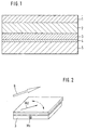
- FIG. 1 schematically shows a preferred layer structure of a sensor element according to the invention.
- the sensor element has a thin magnetic, preferably soft magnetic, layer 3 (reference layer 3).
- the magnetization direction of this reference layer 3 represents the reference direction of the sensor element.
- Applied to the reference layer 3 is a thin, nonmagnetic conductor layer 2 on which a further, preferably soft magnetic layer 1 (detection layer) is applied. is trained.
- the direction of magnetization of this detection layer 1 is dependent on the direction of an external magnetic field B (oriented parallel to the layer surface), as will be explained in detail below.
- an insulator layer 4 is formed, which electrically separates the reference layer 3 from a layer 5 formed as a current conductor. Depending on the current direction in the current conductor layer 5, a magnetic field is induced in the reference layer 3, which leads to a corresponding magnetization of the reference layer 3.
- FIG. 6 The relationship between the direction of current in the layer 5 and the induced magnetization in the reference layer 3 is shown in FIG. If a current Is flowing in the horizontal direction according to the illustration of FIG. 6, a magnetization corresponding to the direction represented by the arrow Ms is induced in the reference layer 3, which is arranged above it and not shown in FIG. In the case of a current flow Ic perpendicular thereto, a magnetization in the direction of the arrow Mc results analogously. For the sake of simplicity, both the magnetization directions or directions of magnetic field arrows, and the corresponding magnetizations or magnetic fields will be referred to in the following.
- FIG. 5 A preferred control of the conductor layer 5 is shown in FIG. It can be seen that the current conductor layer 5 is applied alternately with the mutually perpendicular currents Is, Ic.
- FIG. 2 shows the magnetization Ms of the reference layer 3 when the current Is is applied.
- arrow Ms points into the drawing plane.
- the direction of the external magnetic field to be measured is shown by the arrow B.
- the magnetic field B causes a corresponding magnetization in the detection layer 1, whose direction is indicated by the arrow Md.
- the magnetic field B and the magnetization Md of the detection layer have the same orientation.
- the arrow Mc which represents the direction of magnetization of the reference layer 3 points in a direction parallel to the plane of the drawing. This magnetization is, as already explained, caused by the current Ic in the current conductor layer 5.
- a voltage signal generated by the sensor element is dependent on the relative orientation of the magnetizations Ms, Md or Mc, Md (for example when the magnetic field B is rotating).
- Ms the relative orientation of the magnetizations Ms, Md or Mc, Md (for example when the magnetic field B is rotating).
- Mc the reference-layer magnetization
- FIG. 4 the reference-layer magnetization Mc in Figure 5 shown.
- the magnetization Md is indicated by means of a large arrowhead
- FIGS Magnetizations Ms and Mc shown by means of small arrowheads.
- FIG. 4 shows a sinusoidal dependence of the sensor signal on the angle between the magnetizations Md and Ms, in accordance with FIG. 5 a cosinusoid dependence between the magnetizations Md and Mc.
- a throttle valve 31 provided in an intake pipe 30 of an internal combustion engine has a magnet 32 on an extension formed outside the intake pipe, which generates a magnetic field B corresponding to its orientation dependent on the position of the throttle valve.
- this magnetic field B is a schematically represented (strong enlarged) GMR sensor element 33, which has a structure and an operation as shown above.
- the magnetic field B is aligned parallel to the surface of the sensor element 33 (or to its detection layer, not shown).
Landscapes
- Physics & Mathematics (AREA)
- General Physics & Mathematics (AREA)
- Chemical & Material Sciences (AREA)
- Engineering & Computer Science (AREA)
- Nanotechnology (AREA)
- Crystallography & Structural Chemistry (AREA)
- Condensed Matter Physics & Semiconductors (AREA)
- Measuring Magnetic Variables (AREA)
- Hall/Mr Elements (AREA)
- Magnetic Heads (AREA)
- Measurement Of Length, Angles, Or The Like Using Electric Or Magnetic Means (AREA)
- Transmission And Conversion Of Sensor Element Output (AREA)
Abstract
Description
Die vorliegende Erfindung betrifft ein magnetoresistives Sensorelement, insbesondere ein Winkelsensorelement, nach dem Oberbegriff des Patentanspruchs 1 sowie ein Verfahren zur Bestimmung einer Richtung eines Magnetfeldes nach dem Oberbegriff des Patentanspruchs 6.The present invention relates to a magnetoresistive sensor element, in particular an angle sensor element, according to the preamble of
Sensoren, insbesondere Winkelsensoren, die auf der Grundlage des magnetoresistiven Effektes arbeiten, sind bekannt. Hierbei wird der elektrische Widerstand von Sensorelementen in Abhängigkeit von der Richtung eines äußeren Magnetfeldes gemessen. Verwendung finden insbesondere den anisotropen magnetorestistiven Effekt ausnutzende, sogenannte AMR-Sensoren. Es sind ebenfalls Systeme beschrieben worden, bei welchen sogenannte GMR-Sensorelemente (engl.: Giant-Magneto-Resistance-Effect), insbesondere unter Verwendung von selbstabilisierenden magnetischen Schichten, eingesetzt werden (van den Berg et. al., GMR angle detector with an artificial antiferromagnetic subsystem, Journal of Magnetism and Magnetic Materials 165 (1997) 524-528). Hierbei wird eine erste dünne, sogenannte Referenzschicht dadurch erzeugt, daß zwischen zwei entgegengesetzt magnetisierten Lagen (beispielsweise aus Co) eine antiferromagnetische Kopplungsschicht (beispielsweise aus Cu oder Ru) eingebracht wird. Die magnetische Stabilität der Referenzschicht ist durch diesen Mehrschicht-Aufbau gegenüber einzelnen Co-Schichten um etwa eine Größenordnung erhöht. Die Magnetisierungsrichtung der Referenzschicht, die sogenannte Referenzrichtung, hängt (im Idealfall) nicht von der Richtung des äußeren (zu messenden) Magnetfeldes ab.Sensors, in particular angle sensors, which operate on the basis of the magnetoresistive effect are known. In this case, the electrical resistance of sensor elements is measured as a function of the direction of an external magnetic field. Use find in particular the anisotropic magnetoresistive effect exploiting, so-called AMR sensors. Systems have also been described in which so-called GMR sensor elements (English: giant magneto-resistance effect), in particular using self-stabilizing Magnetic layers (van den Berg et al., GMR angle detector with an artificial antiferromagnetic subsystem, Journal of Magnetism and Magnetic Materials 165 (1997) 524-528). In this case, a first thin, so-called reference layer is produced by introducing an antiferromagnetic coupling layer (for example made of Cu or Ru) between two oppositely magnetized layers (for example from Co). The magnetic stability of the reference layer is increased by about one order of magnitude compared to individual Co layers due to this multilayer structure. The magnetization direction of the reference layer, the so-called reference direction, does not depend (ideally) on the direction of the external (to be measured) magnetic field.
Aus der DE 19520172 A ist eine Magnetisierungseinrichtung für ein magnetoresistives Dünnschicht-Sensorelement mit einem Biasschichtteil bekannt. Mit der Einrichtung ist die Magnetisierungsverteilung des Biasschichtteils eines Sensorelements einzuprägen. Dieses Element weist einen Dünnschichtaufbau auf einem Substrat auf und zeigt einen erhöhten magnetoresistiven Effekt. Die Einrichtung soll einen elektrisch leitenden Leiterbahnteil und Mittel zur Positionierung dieses Leiterbahnteils bezüglich des Sensorelements enthalten. Über den Leiterbahnteil soll dabei ein vorbestimmter Einstellstrom zu führen sein, so dass in dem Biasschichtteil des Sensorelements die vorbestimmte Magnetisierungsverteilung fest einstellbar ist.From DE 19520172 A, a magnetization device for a magnetoresistive thin-film sensor element with a bias layer part is known. With the device, the magnetization distribution of the bias layer part of a sensor element is to be impressed. This element has a thin film structure on a substrate and exhibits an increased magnetoresistive effect. The device should contain an electrically conductive trace part and means for positioning this trace part with respect to the sensor element. In this case, a predetermined setting current is to be conducted via the conductor track part, so that the predetermined magnetization distribution can be fixed in the bias layer part of the sensor element.
Die Referenzschicht ist mit einer dünnen nicht-magnetischen Schicht abgedeckt, auf der wiederum eine dünne weichmagnetische Schicht, die sogenannte Detektionsschicht, ausgebildet ist. Die Detektionsschicht richtet ihre Magnetisierung in Richtung eines äußeren Magnetfeldes aus. Aus der Theorie des magnetoresistiven Effektes ist bekannt, daß ein Sensorsignal einer Funktion R(α) - R0+ ΔR*sin(α) bzw. R(α) = R0 + ΔR*cos(α) folgt, wobei R0 ein Offsetwiderstand, ΔR ein Signalhub des Sensors und α der zu messende Winkel zwischen einer ausgezeichneten Sensorrichtung (insbesondere der Referenzrichtung) und der Richtung des äußeren Magnetfeldes ist.The reference layer is covered with a thin non-magnetic layer, on which in turn a thin soft magnetic layer, the so-called detection layer, is formed. The detection layer directs its magnetization in the direction of an external magnetic field. It is known from the theory of the magnetoresistive effect that a sensor signal follows a function R (α) -R 0 + ΔR * sin (α) or R (α) = R 0 + ΔR * cos (α), where R 0 is a Offsets, ΔR is a signal swing of the sensor and α is the angle to be measured between an excellent sensor direction (in particular the reference direction) and the direction of the external magnetic field.
Derartige AMR-bzw. GMR-Sensoren sind nur mit großem Aufwand als 360°-Winkelsensoren verwendbar. Insbesondere ist es zur Erzielung von ausreichend genauen Meßergebnissen notwendig, wenigstens zwei Sensorelemente zu verschalten, deren jeweilige Sensorsignale rechnerisch verknüpft werden müssen. Bei Verwendung von GMR-Werkstoffen stellt man ferner eine Zerstörung der Sensorfunktion im Falle zu starker Magnetfelder fest.Such AMR or. GMR sensors can only be used with great effort as 360 ° angle sensors. In particular, to obtain sufficiently accurate measurement results, it is necessary to connect at least two sensor elements whose respective sensor signals must be mathematically linked. When GMR materials are used, it is also found that the sensor function is destroyed in the event of excessive magnetic fields.
Es sind ferner auf Hall-Basis arbeitende Winkelsensorelemente bekannt, welche jedoch üblicherweise nur einen Winkelbereich von 120° abdecken können.There are also known Hall-based angle sensor elements are known, which, however, can usually cover only an angular range of 120 °.
Aufgabe der Erfindung ist daher die Schaffung eines Sensors, insbesondere eines Winkelsensors, mit dem der Bereitstellungsaufwand bzw. der Meßaufwand während des Betriebes gegenüber herkömmlichen Sensoren vermindert werden kann.The object of the invention is therefore to provide a sensor, in particular an angle sensor, with which the deployment effort or the measurement effort during operation compared to conventional sensors can be reduced.
Diese Aufgabe wird gelöst durch ein Sensorelement mit den Merkmalen des Patentanspruchs 1 sowie durch ein Verfahren zur Bestimmung der Richtung eines Magnetfeldes mit den Merkmalen des Patentanspruchs 6.This object is achieved by a sensor element having the features of
Erfindungsgemäß ist nun ein Sensorelement bzw. ein Sensor geschaffen, welcher gegenüber herkömmlichen Vorrichtungen dieser Art einen wesentlich einfacheren und kostengünstiger zu realisierenden Aufbau aufweist. Ein Zusammenschalten einer Anzahl von Sensorelementen ist nun nicht mehr nötig, ein zu messender Winkel kann in einfacher Weise mit nur einem Sensorelement ermittelt werden. Somit entfällt auch ein kostenintensives Aufbringen mehrerer Sensorelemente auf ein Substrat. Offset und Empfindlichkeit des Sensorelements sind verbessert, da kein Abgleich unterschiedlicher Sensorelemente durchgeführt werden muß.According to the invention, a sensor element or a sensor is now provided which, compared with conventional devices of this type, has a much simpler and less expensive construction to be realized. An interconnection of a number of sensor elements is now no longer necessary, an angle to be measured in a simple way with only be determined a sensor element. This eliminates a costly application of multiple sensor elements on a substrate. Offset and sensitivity of the sensor element are improved, since no adjustment of different sensor elements must be performed.
Bevorzugte Einsatzgebiete für das erfindungsgemäße Sensorelement sind Lenkradwinkelgeber für die Fahrdynamikregelung von Kraftfahrzeugen, Nockenwellensignalgeber, beispielsweise zur Steuerung eines Motor-Direktstarts, DVE-Drosselverstelleinheiten oder Schiebedachregler.Preferred fields of application for the sensor element according to the invention are steering wheel angle encoders for driving dynamics control of motor vehicles, camshaft signal generators, for example for controlling an engine direct start, DVE throttle adjustment units or sunroof controllers.
Vorteilhafte Ausgestaltungen des erfindungsgemäßen Sensorelements bzw. des erfindungsgemäßen Verfahrens sind Gegenstand der Unteransprüche.Advantageous embodiments of the sensor element or the method according to the invention are the subject of the dependent claims.
Es ist besonders bevorzugt, daß die unterschiedlichen Referenzrichtungen um 90° gegeneinander versetzt sind. Mit dieser Maßnahme lassen sich beispielsweise in einfacher Weise linear unabhängige, insbesondere dem Sinus und Cosinus der Drehrichtung des äußeren Magnetfeldes zugeordnete Signale erzeugen. Unter Verwendung beispielsweise der Arctan-Funktion läßt sich dann in bekannter Weise mit geringem Aufwand die Drehrichtung bzw. der Winkel des äußeren Magnetfeldes bezüglich einer ausgezeichneten Richtung, beispielsweise einer der zwei Referenzrichtungen, bestimmen.It is particularly preferred that the different reference directions are offset by 90 ° from each other. With this measure, for example, linearly independent signals, in particular the sine and cosine of the direction of rotation of the external magnetic field, can be generated in a simple manner. Using, for example, the Arctan function, the direction of rotation or the angle of the external magnetic field with respect to an excellent direction, for example one of the two reference directions, can then be determined in a known manner with little effort.
Zweckmäßigerweise werden die Mittel zur wahlweisen Ausrichtung der Magnetisierungsrichtung von einem Stromleiter gebildet, der von der ersten Schicht mittels einer Isolatorschicht galvanisch getrennt und zur Stromführung in unterschiedlichen Richtungen, insbesondere um 90° zueinander versetzten Richtungen, ausgebildet ist. Mit einem derartigen sogenannten Biasstrom ist die wahlweise Ausrichtung der Magnetisierungsrichtung in einfacher und zuverlässiger Weise erzielbar. Insbesondere mittels Regelung der Stromstärke des Biasstroms ist eine Anpassung der Sensorgenauigkeit an die magnetische Umgebung möglich. Es treten keine thermischen Drifts in dem Sensorelement auf, da der Biasstrom in der Zeit konstant ist bzw. in einfacher Weise konstant regelbar ist. Da zur Schaffung der Referenzmagnetisierung kein hartmagnetisches Material verwendet werden muß, tritt erfindungsgemäß im Falle starker Magnetfelder keine Beeinträchtigung oder Zerstörung der Sensorfunktion auf. Derartige Sensorelemente weisen einen weiten Temperatur-Einsatzbereich auf und sind insbesondere für Kraftfahrzeuge einsetzbar.Expediently, the means for selectively aligning the direction of magnetization are formed by a current conductor, which is galvanically separated from the first layer by means of an insulator layer and designed to conduct current in different directions, in particular directions offset by 90 ° from one another. With such a so-called bias current, the selective alignment of the magnetization direction can be achieved in a simple and reliable manner. In particular, by means of regulation of the current intensity of the bias current, an adaptation of the sensor accuracy to the magnetic environment is possible. There are no thermal drifts in the sensor element, since the bias current is constant in time or can be controlled continuously in a simple manner. Since no hard magnetic material has to be used to provide the reference magnetization, according to the invention, no impairment or destruction of the sensor function occurs in the case of strong magnetic fields. Such sensor elements have a wide temperature range of application and can be used in particular for motor vehicles.
Zweckmäßigerweise ist die erste Schicht aus einem weichmagnetischen Werkstoff hergestellt. Derartige Werkstoffe sind preiswert verfügbar und mittels eines stromleiterinduzierten Magnetfeldes (Biasstrom) magnetisierbar.Conveniently, the first layer is made of a soft magnetic material. Such materials are available inexpensively and by means of a current-induced magnetic field (Biasstrom) magnetizable.
Vorteilhafterweise ist auch die dritte Schicht, die Detektionsschicht des Sensorelements, aus einem weichmagnetischen Werkstoff hergestellt. Hiermit ist eine genaue und verzögerungsfreie Anpassung der Magnetisierungsrichtung der Detektionsschicht an die Richtung des äußeren Magnetfeldes erzielbar.Advantageously, the third layer, the detection layer of the sensor element, made of a soft magnetic material. Hereby is one accurate and delay-free adaptation of the magnetization direction of the detection layer to the direction of the external magnetic field can be achieved.
Gemäß einer bevorzugten Ausführungsform des erfindungsgemäßen Verfahrens handelt es sich bei einem der Sensorsignale um ein dem Sinus des Winkels zwischen der ersten Referenzrichtung und der Magnetisierungsrichtung der dritten Schicht zugeordnetes, und bei einem weiteren der Sensorsignale um ein dem Cosinus des Winkels zwischen der zweiten Referenzrichtung und der Magnetisierungsrichtung der dritten Schicht zugeordnetes Signal. Derartige Signale sind, insbesondere unter Verwendung der Arctan-Funktion, in einfacher Weise auswertbar.According to a preferred embodiment of the method according to the invention, one of the sensor signals is a sinusoid of the angle between the first reference direction and the magnetization direction of the third layer, and in another of the sensor signals a cosine of the angle between the second reference direction and the Magnetization direction of the third layer associated signal. Such signals can be evaluated in a simple manner, in particular using the Arctan function.
Die Erfindung wird nun anhand einer bevorzugten Ausführungsform unter Bezugnahme auf die beigefügte Zeichnung im einzelnen erläutert. In dieser zeigt
Figur 1- eine schematische Schnittansicht des Schichtaufbaus einer bevorzugten Ausführungsform des erfindungsgemäßen Sensorelements,
Figur 2- eine perspektivische Ansicht der oberen drei Schichten des Sensorelements der
Figur 1 mit eingezeichneten Magnetisierungsrichtungen (erste Referenzrichtung), Figur 3- eine perspektivische Ansicht der oberen drei Schichten des Sensorelements der
Figur 1 mit eingezeichneten Magnetisierungsrichtungen (zweite Referenzrichtung), - Figur 4
- den Verlauf des Sensorsignals bei Vorliegen der ersten Referenzrichtung,
Figur 5- den Verlauf des Sensorsignals bei Vorliegen der zweiten Referenzrichtung,
- Figur 6
- eine Draufsicht auf die eine bevorzugte Ausführungsform der Stromleiterschicht des erfindungsgemäßen Sensorelements (ohne die darüberliegenden Schichten),
- Figur 7
- ein Diagramm zur Erläuterung der Strombeaufschlagung der Stromleiterschicht der Figur 6, und
- Figur 8
- eine perspektivische Ansicht einer bevorzugten Anwendung des erfindungsgemäßen Sensorelements.
- FIG. 1
- a schematic sectional view of the layer structure of a preferred embodiment of the sensor element according to the invention,
- FIG. 2
- 3 is a perspective view of the upper three layers of the sensor element of FIG. 1 with magnetization directions (first reference direction) drawn in,
- FIG. 3
- a perspective view of the upper three layers of the sensor element of Figure 1 with Plotted magnetization directions (second reference direction),
- FIG. 4
- the course of the sensor signal in the presence of the first reference direction,
- FIG. 5
- the course of the sensor signal in the presence of the second reference direction,
- FIG. 6
- a top view of the one preferred embodiment of the current conductor layer of the sensor element according to the invention (without the overlying layers),
- FIG. 7
- a diagram for explaining the current application of the current conductor layer of Figure 6, and
- FIG. 8
- a perspective view of a preferred application of the sensor element according to the invention.
In Figur 1 ist ein bevorzugter Schichtaufbau eines erfindungsgemäßen Sensorelements schematisch dargestellt. Das Sensorelement weist eine dünne magnetische, vorzugsweise weichmagnetische, Schicht 3 (Referenzschicht 3) auf. Die Magnetisierungsrichtung dieser Referenzschicht 3 stellt die Referenzrichtung des Sensorelements dar. Auf die Referenzschicht 3 ist eine dünne, nichtmagnetische Leiterschicht 2 aufgebracht, auf welcher eine weitere vorzugsweise weichmagnetische Schicht 1 (Detektionsschicht) ausgebildet ist. Die Magnetisierungsrichtung dieser Detektionsschicht 1 ist abhängig von der Richtung eines (parallel zur Schichtoberfläche orientierten) äußeren Magnetfeldes B, wie weiter unten im einzelnen erläutert wird.FIG. 1 schematically shows a preferred layer structure of a sensor element according to the invention. The sensor element has a thin magnetic, preferably soft magnetic, layer 3 (reference layer 3). The magnetization direction of this
Unter der Referenzschicht 3 ist eine Isolatorschicht 4 ausgebildet, welche die Referenzschicht 3 galvanisch von einer als Stromleiter ausgebildeten Schicht 5 trennt. In Abhängigkeit von der Stromrichtung in der Stromleiterschicht 5 wird in der Referenzschicht 3 ein Magnetfeld induziert, was zu einer entsprechenden Magnetisierung der Referenzschicht 3 führt.Under the
Der Zusammenhang zwischen Stromrichtung in der Schicht 5 und der induzierten Magnetisierung in der Referenzschicht 3 ist in Figur 6 dargestellt. Fließt ein Strom Is gemäß der Darstellung der Figur 6 in waagerechter Richtung wird in der darüber angeordneten, in Figur 6 nicht dargestellten Referenzschicht 3 eine Magnetisierung entsprechend der durch den Pfeil Ms dargestellten Richtung induziert. Bei einem Stromfluß Ic senkrecht hierzu ergibt sich analog eine Magnetisierung in Richtung des Pfeiles Mc. Der Einfachheit halber werden im folgenden sowohl die Magnetisierungsrichtungen bzw. Richtungen von Magnetfeldern darstellenden Pfeile, als auch die entsprechenden Magnetisierungen bzw. Magnetfelder in gleicher Weise bezeichnet.The relationship between the direction of current in the
Eine bevorzugte Ansteuerung der Stromleiterschicht 5 ist in Figur 7 dargestellt. Man erkennt, daß die Stromleiterschicht 5 abwechselnd mit den senkrecht zueinander verlaufenden Strömen Is, Ic beaufschlagt wird.A preferred control of the
In Figur 2 ist die Magnetisierung Ms der Referenzschicht 3 bei Anliegen des Stromes Is dargestellt. In dieser Darstellung weist Pfeil Ms in die Zeichenebene hinein. Die zu messende Richtung des äußeren Magnetfeldes ist mittels des Pfeiles B dargestellt. Das Magnetfeld B verursacht in der Detektionsschicht 1 eine entsprechende Magnetisierung, deren Richtung durch den Pfeil Md angedeutet ist. Das Magnetfeld B und die Magnetisierung Md der Detektionsschicht weisen die gleiche Orientierung auf.FIG. 2 shows the magnetization Ms of the
In der Figur 3 weist der die Magnetisierungsrichtung der Referenzschicht 3 darstellende Pfeil Mc in eine Richtung parallel zur Zeichenebene. Diese Magnetisierung ist, wie bereits erläutert, verursacht durch den Strom Ic in der Stromleiterschicht 5.In FIG. 3, the arrow Mc, which represents the direction of magnetization of the
Ein von dem Sensorelement erzeugtes Spannungssignal ist (beispielsweise bei drehendem Magnetfeld B) abhängig von der relativen Orientierung der Magnetisierungen Ms, Md bzw. Mc, Md. Für die Referenzschicht-Magnetisierung Ms ist diese Abhängigkeit in Figur 4, für die Referenzschicht-Magnetisierung Mc in Figur 5 dargestellt. Zur Veranschaulichung sind in diesen Figuren zusätzlich zu den jeweiligen Winkeln zwischen den Magnetisierungen die Magnetisierung Md mittels einer großen Pfeilspitze, und die Magnetisierungen Ms bzw. Mc mittels kleiner Pfeilspitzen dargestellt.A voltage signal generated by the sensor element is dependent on the relative orientation of the magnetizations Ms, Md or Mc, Md (for example when the magnetic field B is rotating). For the reference-layer magnetization Ms, this dependence is shown in FIG. 4, for the reference-layer magnetization Mc in Figure 5 shown. By way of illustration, in these figures, in addition to the respective angles between the magnetizations, the magnetization Md is indicated by means of a large arrowhead, and FIGS Magnetizations Ms and Mc shown by means of small arrowheads.
In Figur 4 erkennt man eine sinusförmige Abhängigkeit des Sensorsignals von dem Winkel zwischen den Magnetisierungen Md und Ms, in Figur 5 entsprechend eine cosinusförmige Abhängigkeit zwischen den Magnetisierungen Md und Mc.FIG. 4 shows a sinusoidal dependence of the sensor signal on the angle between the magnetizations Md and Ms, in accordance with FIG. 5 a cosinusoid dependence between the magnetizations Md and Mc.
Insgesamt erhält man also für jeden Winkel zwischen dem äußeren Magnetfeld B (bzw. der Richtung der Magnetisierung Md der Detektorschicht 1) und dem Sensorelement ein vom Sinus und ein vom Cosinus dieses Winkels abhängiges Signal. Mit diesen zwei Signalen läßt sich unter Zuhilfenahme der Arcustangens-Funktion der tatsächliche bzw. mechanische Winkel zwischen dem äußeren Magnetfeld B und einer beliebigen ausgezeichneten Richtung, beispielsweise einer der zwei Referenzrichtungen der Referenzschicht 3, bestimmen. Bei herkömmlichen Sensoren war es notwendig, für das Sinussignal und das Cosinussignal jeweils verschiedene, unterschiedlich orientierte Sensorelemente vorzusehen.Overall, therefore, one obtains for each angle between the external magnetic field B (or the direction of the magnetization Md of the detector layer 1) and the sensor element a signal dependent on the sine and on the cosine of this angle. With these two signals, the actual or mechanical angle between the external magnetic field B and any desired direction, for example one of the two reference directions of the
Anhand der Figur 8 wird abschließend ein bevorzugtes Anwendungsbeispiel für das erfindungsgemäße Sensorelement dargestellt. Eine in einem Ansaugrohr 30 eines Verbrennungsmotors vorgesehene Drosselklappe 31 weist an einer außerhalb des Ansaugrohres ausgebildeten Verlängerung einen Magneten 32 auf, welcher entsprechend seiner von der Stellung der Drosselklappe abhängigen Orientierung ein Magnetfeld B erzeuge. In dem Einflußbereich dieses Magnetfeldes B ist ein schematisch dargestelltes (stark vergrößertes) GMR-Sensorelement 33 angeordnet, welches einen Aufbau und eine Funktionsweise wie oben dargestellt aufweist. Das Magnetfeld B ist parallel zu der Oberfläche des Sensorelements 33 (bzw. zu dessen nicht dargestellter Detektionsschicht) ausgerichtet. Mittels lediglich dieses einen Sensorelements ist in der beschriebenen Weise der Drosselklappenwinkel der Drosselklappe 31 in einfacher Weise bestimmbar.Finally, a preferred application example for the sensor element according to the invention is shown with reference to FIG. A throttle valve 31 provided in an
Claims (7)
- Magnetoresistive sensor element, in particular angle sensor element, having a first, magnetic layer (3) whose magnetization direction represents a reference direction, a second, nonmagnetic layer (2) which is formed on the first layer (3), and a third, magnetic layer (1) which is formed on the second layer (2) and whose magnetization direction can be influenced by an external magnetic field, characterized by means (5) for alternately orienting the magnetization direction of the first layer (3) in a different manner in order to provide different reference directions which are offset with respect to one another.
- Sensor element according to Claim 1, characterized in that the different reference directions are offset by 90° with respect to one another.
- Sensor element according to either of Claims 1 and 2, characterized in that the means (5) are formed by a current conductor which is electrically isolated from the first layer (3) by means of an insulator layer (4) and is designed to carry current in different directions, in particular directions which are offset by 90° to one another.
- Sensor element according to one of the preceding claims, characterized in that the first layer (3) is produced from a soft-magnetic material.
- Sensor element according to one of the preceding claims, characterized in that the third layer (1) is produced from a soft-magnetic material.
- Method for determining the direction of a magnetic field using a sensor element according to one of the preceding claims, characterized in that the means (5) alternately produce different reference directions in the first layer (3) of the sensor element, with a sensor signal being determined for each reference direction as a function of an angle between the respective reference direction and a magnetization direction of the third layer (1) of the sensor element, this magnetization direction being induced by the magnetic field.
- Method according to Claim 6, characterized in that one of the sensor signals is a signal which is associated with the sine of the angle between the first reference direction and the magnetization direction of the third layer (1), and a further one of the sensor signals is a signal which is associated with the cosine of the angle between the second reference direction and the magnetization direction of the third layer (1).
Applications Claiming Priority (3)
| Application Number | Priority Date | Filing Date | Title |
|---|---|---|---|
| DE19843348A DE19843348A1 (en) | 1998-09-22 | 1998-09-22 | Magneto-resistive sensor element for measurement of external magnetic field angle, especially in automotive applications, has device for generating varying magnetic reference field in a reference magnetic layer |
| DE19843348 | 1998-09-22 | ||
| PCT/DE1999/001631 WO2000017667A1 (en) | 1998-09-22 | 1999-06-02 | Magnetoresistive sensor element with selective magnetization direction of the bias layer |
Publications (2)
| Publication Number | Publication Date |
|---|---|
| EP1046047A1 EP1046047A1 (en) | 2000-10-25 |
| EP1046047B1 true EP1046047B1 (en) | 2006-06-07 |
Family
ID=7881777
Family Applications (1)
| Application Number | Title | Priority Date | Filing Date |
|---|---|---|---|
| EP99936399A Expired - Lifetime EP1046047B1 (en) | 1998-09-22 | 1999-06-02 | Magnetoresistive sensor element with selective magnetization direction of the bias layer |
Country Status (8)
| Country | Link |
|---|---|
| US (1) | US6373247B1 (en) |
| EP (1) | EP1046047B1 (en) |
| JP (1) | JP2002525610A (en) |
| KR (1) | KR100606584B1 (en) |
| AU (1) | AU759610B2 (en) |
| DE (2) | DE19843348A1 (en) |
| TW (1) | TW440704B (en) |
| WO (1) | WO2000017667A1 (en) |
Families Citing this family (20)
| Publication number | Priority date | Publication date | Assignee | Title |
|---|---|---|---|---|
| DE10230455A1 (en) | 2002-07-06 | 2004-01-22 | Robert Bosch Gmbh | Method for setting or locally changing a magnetization in a layer of a magnetoresistive layer arrangement, heating stamp for heating the magnetoresistive layer arrangement and their use |
| WO2004017086A1 (en) | 2002-07-26 | 2004-02-26 | Robert Bosch Gmbh | Gmr sensor element and use thereof |
| US7504824B2 (en) * | 2004-10-21 | 2009-03-17 | International Business Machines Corporation | Magnetic sensor with offset magnetic field |
| JP2006269955A (en) * | 2005-03-25 | 2006-10-05 | Mitsubishi Electric Corp | Magnetic field detecting device |
| KR100668488B1 (en) * | 2005-06-21 | 2007-01-15 | 대성전기공업 주식회사 | Steering Wheel Angular Velocity Sensor |
| US8665113B2 (en) * | 2005-10-31 | 2014-03-04 | Wavetronix Llc | Detecting roadway targets across beams including filtering computed positions |
| JP4607049B2 (en) * | 2006-02-23 | 2011-01-05 | 株式会社デンソー | Rotation angle detector |
| JP2011127909A (en) * | 2009-12-15 | 2011-06-30 | Alps Electric Co Ltd | Rotation detection system |
| WO2011144680A1 (en) | 2010-05-19 | 2011-11-24 | Saint Gobain Glass France | Bandwidth-optimized antenna by means of a hybrid design comprising planar and linear antenna elements |
| US9310446B2 (en) * | 2012-10-18 | 2016-04-12 | Analog Devices, Inc. | Magnetic field direction detector |
| US9377327B2 (en) * | 2013-06-28 | 2016-06-28 | Analog Devices Global | Magnetic field direction sensor |
| US9529060B2 (en) | 2014-01-09 | 2016-12-27 | Allegro Microsystems, Llc | Magnetoresistance element with improved response to magnetic fields |
| JP6763887B2 (en) | 2015-06-05 | 2020-09-30 | アレグロ・マイクロシステムズ・エルエルシー | Spin valve magnetoresistive sensor with improved response to magnetic field |
| CN205066678U (en) * | 2015-10-26 | 2016-03-02 | 深圳市道通智能航空技术有限公司 | Angle displacement detection device , motor corner control system , cloud platform and aircraft |
| US11187763B2 (en) | 2016-03-23 | 2021-11-30 | Analog Devices International Unlimited Company | Offset compensation for magnetic field detector |
| US11022661B2 (en) | 2017-05-19 | 2021-06-01 | Allegro Microsystems, Llc | Magnetoresistance element with increased operational range |
| US10620279B2 (en) | 2017-05-19 | 2020-04-14 | Allegro Microsystems, Llc | Magnetoresistance element with increased operational range |
| US10739165B2 (en) | 2017-07-05 | 2020-08-11 | Analog Devices Global | Magnetic field sensor |
| CN112556569B (en) * | 2020-11-17 | 2022-05-31 | 西人马帝言(北京)科技有限公司 | Method, device and equipment for temperature compensation of sensor and storage medium |
| US11719771B1 (en) | 2022-06-02 | 2023-08-08 | Allegro Microsystems, Llc | Magnetoresistive sensor having seed layer hysteresis suppression |
Family Cites Families (4)
| Publication number | Priority date | Publication date | Assignee | Title |
|---|---|---|---|---|
| DE19520172A1 (en) * | 1995-06-01 | 1996-12-05 | Siemens Ag | Magnetization device for a magnetoresistive thin-film sensor element with a bias layer part |
| US5648885A (en) * | 1995-08-31 | 1997-07-15 | Hitachi, Ltd. | Giant magnetoresistive effect sensor, particularly having a multilayered magnetic thin film layer |
| JPH09126780A (en) * | 1995-10-31 | 1997-05-16 | Tokin Corp | Magnetic direction sensor |
| JP3461999B2 (en) * | 1996-03-28 | 2003-10-27 | 株式会社東芝 | Magnetoresistive element |
-
1998
- 1998-09-22 DE DE19843348A patent/DE19843348A1/en not_active Ceased
-
1999
- 1999-06-02 EP EP99936399A patent/EP1046047B1/en not_active Expired - Lifetime
- 1999-06-02 US US09/530,699 patent/US6373247B1/en not_active Expired - Fee Related
- 1999-06-02 AU AU51516/99A patent/AU759610B2/en not_active Ceased
- 1999-06-02 JP JP2000571277A patent/JP2002525610A/en active Pending
- 1999-06-02 WO PCT/DE1999/001631 patent/WO2000017667A1/en active IP Right Grant
- 1999-06-02 KR KR1020007005473A patent/KR100606584B1/en not_active IP Right Cessation
- 1999-06-02 DE DE59913523T patent/DE59913523D1/en not_active Expired - Lifetime
- 1999-06-07 TW TW088109404A patent/TW440704B/en not_active IP Right Cessation
Also Published As
| Publication number | Publication date |
|---|---|
| WO2000017667A1 (en) | 2000-03-30 |
| KR20010032267A (en) | 2001-04-16 |
| KR100606584B1 (en) | 2006-08-01 |
| AU5151699A (en) | 2000-04-10 |
| US6373247B1 (en) | 2002-04-16 |
| EP1046047A1 (en) | 2000-10-25 |
| DE59913523D1 (en) | 2006-07-20 |
| JP2002525610A (en) | 2002-08-13 |
| AU759610B2 (en) | 2003-04-17 |
| DE19843348A1 (en) | 2000-03-23 |
| TW440704B (en) | 2001-06-16 |
Similar Documents
| Publication | Publication Date | Title |
|---|---|---|
| EP1046047B1 (en) | Magnetoresistive sensor element with selective magnetization direction of the bias layer | |
| DE19729808C2 (en) | sensor device | |
| DE19647320C2 (en) | Magnetic field sensor for detecting the change in a magnetic field | |
| EP2396666B1 (en) | Assembly for measuring at least one component of a magnetic field | |
| EP0226574B1 (en) | Magnetoresistive sensor for producing electric signals | |
| DE19851839B4 (en) | magnetic field detector | |
| EP1049908B1 (en) | System for detecting the angle of rotation of a rotatable element | |
| DE19539722C2 (en) | Device for detecting a change in an angle or the field strength of a magnetic field | |
| DE19649400C5 (en) | Magnetic field sensing | |
| EP0990120A1 (en) | Angle sensor and a method for determining an angle | |
| WO1996029568A1 (en) | Sensor for determining a rotation angle or speed | |
| DE102005022596A1 (en) | Arrangement for intrinsically safe wheel speed detection | |
| DE102007013755A1 (en) | Indicator element for a magnetic rotary encoder | |
| EP1567878B1 (en) | Magnetoresistive sensor element and method for reducing the angular error of a magnetoresistive sensor element | |
| WO1986000986A1 (en) | Magnetoresistive device for measuring magnetic field variations and method for fabricating the same | |
| DE19647420B4 (en) | Device for detecting a magnetic field | |
| EP1399750A1 (en) | Magneto-resistive layer arrangement and gradiometer with said layer arrangement | |
| DE19642752B4 (en) | Measuring device for detecting the change of a magnetic field | |
| DE19612422C2 (en) | Potentiometer device with a linearly displaceable control element and signal-generating means | |
| DE19949714A1 (en) | Magnetically sensitive component used as a sensor element operating according to a spin-valve principle in vehicles comprises two magneto-resistive layer systems with a reference layer, an intermediate layer and a detection layer | |
| WO2002082111A1 (en) | Method for adjusting magnetization in a layered arrangement and use thereof | |
| DE19851323B4 (en) | Magnetic detector | |
| WO2007006742A1 (en) | Angle of rotation sensor | |
| DE10257253A1 (en) | Giant magnetoresistive sensor for motor vehicle cam and crank shafts has eight magnetoresistive elements in two Wheatstone bridges | |
| DE10250319A1 (en) | Device for determining the rotation of a shaft comprises a shaft, a transmitting magnet arranged on the surface of a front side of the shaft or integrated in the region of the surface of the front side, and a GMR sensor element |
Legal Events
| Date | Code | Title | Description |
|---|---|---|---|
| PUAI | Public reference made under article 153(3) epc to a published international application that has entered the european phase |
Free format text: ORIGINAL CODE: 0009012 |
|
| AK | Designated contracting states |
Kind code of ref document: A1 Designated state(s): DE FR GB IT |
|
| 17P | Request for examination filed |
Effective date: 20001002 |
|
| RIN1 | Information on inventor provided before grant (corrected) |
Inventor name: FREITAG, MARTIN Inventor name: JOST, FRANZ Inventor name: KITTEL, HARTMUT Inventor name: MARX, KLAUS |
|
| 17Q | First examination report despatched |
Effective date: 20050607 |
|
| GRAP | Despatch of communication of intention to grant a patent |
Free format text: ORIGINAL CODE: EPIDOSNIGR1 |
|
| GRAS | Grant fee paid |
Free format text: ORIGINAL CODE: EPIDOSNIGR3 |
|
| GRAA | (expected) grant |
Free format text: ORIGINAL CODE: 0009210 |
|
| AK | Designated contracting states |
Kind code of ref document: B1 Designated state(s): DE FR GB IT |
|
| REG | Reference to a national code |
Ref country code: GB Ref legal event code: FG4D Free format text: NOT ENGLISH |
|
| REF | Corresponds to: |
Ref document number: 59913523 Country of ref document: DE Date of ref document: 20060720 Kind code of ref document: P |
|
| GBT | Gb: translation of ep patent filed (gb section 77(6)(a)/1977) |
Effective date: 20060927 |
|
| ET | Fr: translation filed | ||
| PLBE | No opposition filed within time limit |
Free format text: ORIGINAL CODE: 0009261 |
|
| STAA | Information on the status of an ep patent application or granted ep patent |
Free format text: STATUS: NO OPPOSITION FILED WITHIN TIME LIMIT |
|
| 26N | No opposition filed |
Effective date: 20070308 |
|
| PGFP | Annual fee paid to national office [announced via postgrant information from national office to epo] |
Ref country code: FR Payment date: 20100706 Year of fee payment: 12 |
|
| PGFP | Annual fee paid to national office [announced via postgrant information from national office to epo] |
Ref country code: IT Payment date: 20100624 Year of fee payment: 12 |
|
| PGFP | Annual fee paid to national office [announced via postgrant information from national office to epo] |
Ref country code: GB Payment date: 20100401 Year of fee payment: 12 Ref country code: DE Payment date: 20100824 Year of fee payment: 12 |
|
| GBPC | Gb: european patent ceased through non-payment of renewal fee |
Effective date: 20110602 |
|
| PG25 | Lapsed in a contracting state [announced via postgrant information from national office to epo] |
Ref country code: IT Free format text: LAPSE BECAUSE OF NON-PAYMENT OF DUE FEES Effective date: 20110602 |
|
| REG | Reference to a national code |
Ref country code: FR Ref legal event code: ST Effective date: 20120229 |
|
| PG25 | Lapsed in a contracting state [announced via postgrant information from national office to epo] |
Ref country code: DE Free format text: LAPSE BECAUSE OF NON-PAYMENT OF DUE FEES Effective date: 20120103 Ref country code: FR Free format text: LAPSE BECAUSE OF NON-PAYMENT OF DUE FEES Effective date: 20110630 |
|
| REG | Reference to a national code |
Ref country code: DE Ref legal event code: R119 Ref document number: 59913523 Country of ref document: DE Effective date: 20120103 |
|
| PG25 | Lapsed in a contracting state [announced via postgrant information from national office to epo] |
Ref country code: GB Free format text: LAPSE BECAUSE OF NON-PAYMENT OF DUE FEES Effective date: 20110602 |