EP1046005B1 - Electromagnetically actuatable hydraulic proportional valve - Google Patents
Electromagnetically actuatable hydraulic proportional valve Download PDFInfo
- Publication number
- EP1046005B1 EP1046005B1 EP99953718A EP99953718A EP1046005B1 EP 1046005 B1 EP1046005 B1 EP 1046005B1 EP 99953718 A EP99953718 A EP 99953718A EP 99953718 A EP99953718 A EP 99953718A EP 1046005 B1 EP1046005 B1 EP 1046005B1
- Authority
- EP
- European Patent Office
- Prior art keywords
- proportional valve
- hydraulic proportional
- electromagnetically actuatable
- sealing element
- valve according
- Prior art date
- Legal status (The legal status is an assumption and is not a legal conclusion. Google has not performed a legal analysis and makes no representation as to the accuracy of the status listed.)
- Expired - Lifetime
Links
Images


Classifications
-
- F—MECHANICAL ENGINEERING; LIGHTING; HEATING; WEAPONS; BLASTING
- F16—ENGINEERING ELEMENTS AND UNITS; GENERAL MEASURES FOR PRODUCING AND MAINTAINING EFFECTIVE FUNCTIONING OF MACHINES OR INSTALLATIONS; THERMAL INSULATION IN GENERAL
- F16K—VALVES; TAPS; COCKS; ACTUATING-FLOATS; DEVICES FOR VENTING OR AERATING
- F16K1/00—Lift valves or globe valves, i.e. cut-off apparatus with closure members having at least a component of their opening and closing motion perpendicular to the closing faces
- F16K1/32—Details
- F16K1/34—Cutting-off parts, e.g. valve members, seats
- F16K1/36—Valve members
-
- F—MECHANICAL ENGINEERING; LIGHTING; HEATING; WEAPONS; BLASTING
- F15—FLUID-PRESSURE ACTUATORS; HYDRAULICS OR PNEUMATICS IN GENERAL
- F15B—SYSTEMS ACTING BY MEANS OF FLUIDS IN GENERAL; FLUID-PRESSURE ACTUATORS, e.g. SERVOMOTORS; DETAILS OF FLUID-PRESSURE SYSTEMS, NOT OTHERWISE PROVIDED FOR
- F15B13/00—Details of servomotor systems ; Valves for servomotor systems
- F15B13/02—Fluid distribution or supply devices characterised by their adaptation to the control of servomotors
- F15B13/04—Fluid distribution or supply devices characterised by their adaptation to the control of servomotors for use with a single servomotor
- F15B13/0401—Valve members; Fluid interconnections therefor
- F15B13/0405—Valve members; Fluid interconnections therefor for seat valves, i.e. poppet valves
-
- F—MECHANICAL ENGINEERING; LIGHTING; HEATING; WEAPONS; BLASTING
- F15—FLUID-PRESSURE ACTUATORS; HYDRAULICS OR PNEUMATICS IN GENERAL
- F15B—SYSTEMS ACTING BY MEANS OF FLUIDS IN GENERAL; FLUID-PRESSURE ACTUATORS, e.g. SERVOMOTORS; DETAILS OF FLUID-PRESSURE SYSTEMS, NOT OTHERWISE PROVIDED FOR
- F15B13/00—Details of servomotor systems ; Valves for servomotor systems
- F15B13/02—Fluid distribution or supply devices characterised by their adaptation to the control of servomotors
- F15B13/04—Fluid distribution or supply devices characterised by their adaptation to the control of servomotors for use with a single servomotor
- F15B13/044—Fluid distribution or supply devices characterised by their adaptation to the control of servomotors for use with a single servomotor operated by electrically-controlled means, e.g. solenoids, torque-motors
- F15B13/0442—Fluid distribution or supply devices characterised by their adaptation to the control of servomotors for use with a single servomotor operated by electrically-controlled means, e.g. solenoids, torque-motors with proportional solenoid allowing stable intermediate positions
-
- F—MECHANICAL ENGINEERING; LIGHTING; HEATING; WEAPONS; BLASTING
- F16—ENGINEERING ELEMENTS AND UNITS; GENERAL MEASURES FOR PRODUCING AND MAINTAINING EFFECTIVE FUNCTIONING OF MACHINES OR INSTALLATIONS; THERMAL INSULATION IN GENERAL
- F16K—VALVES; TAPS; COCKS; ACTUATING-FLOATS; DEVICES FOR VENTING OR AERATING
- F16K31/00—Actuating devices; Operating means; Releasing devices
- F16K31/02—Actuating devices; Operating means; Releasing devices electric; magnetic
- F16K31/06—Actuating devices; Operating means; Releasing devices electric; magnetic using a magnet, e.g. diaphragm valves, cutting off by means of a liquid
- F16K31/0644—One-way valve
- F16K31/0655—Lift valves
-
- Y—GENERAL TAGGING OF NEW TECHNOLOGICAL DEVELOPMENTS; GENERAL TAGGING OF CROSS-SECTIONAL TECHNOLOGIES SPANNING OVER SEVERAL SECTIONS OF THE IPC; TECHNICAL SUBJECTS COVERED BY FORMER USPC CROSS-REFERENCE ART COLLECTIONS [XRACs] AND DIGESTS
- Y10—TECHNICAL SUBJECTS COVERED BY FORMER USPC
- Y10T—TECHNICAL SUBJECTS COVERED BY FORMER US CLASSIFICATION
- Y10T137/00—Fluid handling
- Y10T137/2278—Pressure modulating relays or followers
Definitions
- the invention is based on an electromagnetic actuable, hydraulic proportional valve accordingly the type of claim 1.
- a valve is for example known from FR-A-1 277 797.
- Electromagnetically operated Proportional valves are used, among other things, to control the Pressure in hydraulic circuits, for example in Automatic transmissions used by motor vehicles.
- On such a proportional valve is exemplary from the DE-Gm 94 10 219 known.
- This proportional valve has a magnetic part, the anchor of which is on a closing member a valve part acts and with this one Flat seat valve forms. Flat seat valves stand out especially due to their insensitivity to Misalignment between the anchor and the striker off, but tend to on account of the flow conditions Locking element to vibrate over the course of the operating time Can cause leaks and wear.
- the invention has electromagnetic Actuable, hydraulic proportional valve with the characterizing features of claim 1 the advantage that it is against temperature influences and flow-related vibration excitations much more stable behaves.
- the pressure / current characteristics of the proportional valve thereby have a more constant and steady course, whereby the effort to program a control for the proportional valve is minimized.
- the Sealing properties and the wear behavior of the Proportional valve according to the invention are improved, Sensors for the detection and compensation of Temperature influences in hydraulic circuits can be saved become. Further advantages or advantageous further training the invention result from the dependent claims and Description.
- sub-claims 3 and 4 to 8 are two Embodiments of locking members specified. That in Closing member described claim 3 is characterized by its simple execution and its inexpensive Manufacture from, the closing member according to claims 4 to 8 is due to its guidance decoupled from the anchor particularly insensitive to misalignment.
- the other subclaims are production engineering advantageous configurations and particularly suitable Areas of application for the invention Proportional valves disclosed.
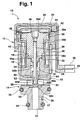
- Figures 1 and 2 each show one of the exemplary embodiments in longitudinal section, in FIGS. 3 and 4, the closing member 60 is enlarged as a single part shown.
- the proportional valves shown in Figures 1 and 2 10 each consist of a magnetic part 12 and one integrally connected to this valve part 14, the coaxial is arranged to the magnetic part 12.
- the magnetic part 12 comprises a coil 18 wound on a bobbin 16, the electrically controllable by means of lines 20 and contacts 22 is.
- the lines 20 are in a plastic part 24 injected in one piece with the bobbin 16 is connected and at the free end of the contacts 22 receiving connector housing 26 is provided.
- the coil 18 is hollow cylindrical and takes on a core 28 at its end facing the valve part 14 stationary on the sections of the inside of the coil 18th protrudes.
- This core 28 has a central Longitudinal bore 30 on the inside of the coil 18th located end in a flat depression 32.
- a guide sleeve 34 circumferential collar 34a At the bottom of the Flat countersink 32 is supported by a guide sleeve 34 circumferential collar 34a.
- the guide sleeve 34 has one Valve part 14 facing and in the longitudinal bore 30th of the core 28 extending neck 34b, the Inner wall at the end of the guide sleeve 34 on the valve part side forms an axial guide for a tappet 36.
- the latter is firmly connected to an anchor 38, which is on the Valve part 14 facing away from the end of the coil 18.
- the anchor 38 has the shape of a T and is divided into one the end face of the coil 18 covering head 38a and a shaft 38b projecting into the coil 18.
- the shaft 38b ends in a projection 38c, which extends into the flat depression 32 of the core 28 can dip.
- a secondary air gap 40 By a relative movement of the armature 38 with respect to the coil 18 to allow between the shaft 38b and Coil body 16 is a secondary air gap 40.
- a working air gap 41 which allows a lifting movement of the armature 38, is between the facing end faces of the armature 38 and the Kerns 28 recognizable.
- a spring washer 39 at the end facing away from the valve part 14 of the proportional valve 10.
- This spring washer 39 is in the Area of their outer circumference between a step of a Housing 42 of the magnetic part 12 and one of these housings 42 clamped to the outside cover 44.
- the lid 44 and the housing 42 are caulked together.
- Downtown the spring washer 39, a recess 46 is provided, the with a corresponding projection 38d of the armature 38 is also caulked.
- the housing 42 of the magnetic part 12 is essentially a coating of the Magnetic part 12 forming individual components with plastic generated. In this housing 42 is a flow guide metal sleeve 48 surrounding coil 18 is injected.
- the housing 42 of the proportional valve 10 goes into that Housing 43 of the valve part 14 over.
- a Inlet channel 50, a return channel 52 and a working channel 54 educated.
- the Inlet 50 and the return channel 52 are by means of ring seals 56 sealed against each other or to the outside.
- the inlet channel 50 is to form an orifice 57 in the flow direction once graduated in the inner diameter, is facing away from Magnetic part 12 and ends bluntly in the consumer channel 50 on.
- the valve part 14 faces horizontal return channel 52 as a continuous, i.e. the Working channel 54 penetrating, recess formed.
- the closing member 60 is divided into a cylindrical guide section 60a on the magnetic part side, an adjoining connecting section 60b and a sealing body 60c which interacts with the perforated diaphragm 55.
- the guide section 60a and the connecting section 60b have a cylindrical cross section
- the sealing body 60c is conical and, for reasons of flow technology, is curved outward in a dome-like manner on the end face of the valve part.
- the cross-section of the connecting section 60b has the shape of an annular groove with, for example, walls running at right angles to one another. This results in a flow separation edge 60d at the transition point from the sealing body 60c to the connecting section 60b, which significantly reduces the temperature sensitivity of the proportional valve 10.
- the closing member 60 is guided via the guides of the plunger 36 or the armature 38, separate guides 64 as are not necessary in the first embodiment.
Landscapes
- Engineering & Computer Science (AREA)
- General Engineering & Computer Science (AREA)
- Mechanical Engineering (AREA)
- Physics & Mathematics (AREA)
- Fluid Mechanics (AREA)
- Magnetically Actuated Valves (AREA)
- Control Of Transmission Device (AREA)
Description
Die Erfindung geht aus von einem elektromagnetisch betätigbaren, hydraulischen Proportionalventil entsprechend der Gattung des Anspruchs 1. Ein derartiges Ventil ist beispielsweise aus der FR-A-1 277 797 bekannt. Elektromagnetisch betätigbare Proportionalventile werden unter anderem zur Regelung des Druckes in hydraulischen Schaltkreisen, beispielsweise in Automatikgetrieben von Kraftfahrzeugen eingesetzt. Ein derartiges Proportionalventil ist exemplarisch aus der DE-Gm 94 10 219 bekannt. Dieses Proportionalventil hat einen Magnetteil, dessen Anker auf ein Schließglied eines Ventilteils einwirkt und mit diesem ein Flachsitzventil bildet. Flachsitzventile zeichnen sich insbesondere durch ihre Unempfindlichkeit gegenüber Fluchtungsfehlern zwischen dem Anker und dem Schließglied aus, neigen allerdings aufgrund der Strömungsverhältnisse am Schließglied zu Schwingungen, die im Laufe der Betriebszeit Undichtigkeiten und Verschleiß verursachen können. Ohne Gegenmaßnahmen am Schließglied ist dessen Funktion zudem stark von der Temperatur, d.h. der Viskosität und damit der viskosen Reibung, des Druckmittels abhängig. Dies kann zu unstetigen Druck-/Strom-Kennlinien des Proportionalventils führen. Beide Effekte sind unerwünscht, da sie die Funktionseigenschaften eines angeschlossenen Hydraulikkreises beeinträchtigen.The invention is based on an electromagnetic actuable, hydraulic proportional valve accordingly the type of claim 1. Such a valve is for example known from FR-A-1 277 797. Electromagnetically operated Proportional valves are used, among other things, to control the Pressure in hydraulic circuits, for example in Automatic transmissions used by motor vehicles. On such a proportional valve is exemplary from the DE-Gm 94 10 219 known. This proportional valve has a magnetic part, the anchor of which is on a closing member a valve part acts and with this one Flat seat valve forms. Flat seat valves stand out especially due to their insensitivity to Misalignment between the anchor and the striker off, but tend to on account of the flow conditions Locking element to vibrate over the course of the operating time Can cause leaks and wear. Without Countermeasures on the closing element is also its function strongly from temperature, i.e. the viscosity and thus the viscous friction, depending on the pressure medium. This can be too discontinuous pressure / current characteristics of the proportional valve to lead. Both Effects are undesirable because of their functional properties of a connected hydraulic circuit.
Demgegenüber weist das erfindungsgemäße elektromagnetisch betätigbare, hydraulische Proportionalventil mit den kennzeichnenden Merkmalen des Anspruchs 1 den Vorteil auf, daß es sich gegenüber Temperatureinflüssen und strömungsbedingten Schwingungsanregungen wesentlich stabiler verhält. Die Druck-/Strom-Kennlinien des Proportionalventils haben dadurch einen konstanteren und stetigeren Verlauf, wodurch der Aufwand zur Programmierung einer Ansteuerung für das Proportionalventil minimiert wird. Die Dichteigenschaften und das Verschleißverhalten des erfindungsgemäßen Proportionalventils sind verbessert, Sensoren zur Erfassung und Kompensation von Temperatureinflüssen in Hydraulikkreisen können eingespart werden. Weitere Vorteile oder vorteilhafte Weiterbildungen der Erfindung ergeben sich aus den Unteransprüchen und der Beschreibung.In contrast, the invention has electromagnetic Actuable, hydraulic proportional valve with the characterizing features of claim 1 the advantage that it is against temperature influences and flow-related vibration excitations much more stable behaves. The pressure / current characteristics of the proportional valve thereby have a more constant and steady course, whereby the effort to program a control for the proportional valve is minimized. The Sealing properties and the wear behavior of the Proportional valve according to the invention are improved, Sensors for the detection and compensation of Temperature influences in hydraulic circuits can be saved become. Further advantages or advantageous further training the invention result from the dependent claims and Description.
In den Unteransprüchen 3 und 4 bis 8 sind zwei Ausführungsbeispiele von Schließgliedern angegeben. Das im Anspruch 3 beschriebene Schließglied zeichnet sich durch seine einfache Ausführung und seine preisgünstige Herstellung aus, das Schließglied gemäß den Ansprüchen 4 bis 8 ist aufgrund seiner vom Anker entkoppelten Führung besonders unempfindlich gegenüber Fluchtungsfehlern. In den übrigen Unteransprüchen sind fertigungstechnisch vorteilhafte Ausgestaltungen und besonders geeignete Einsatzbereiche für die erfindungsgemäßen Proportionalventile offenbart. In sub-claims 3 and 4 to 8 are two Embodiments of locking members specified. That in Closing member described claim 3 is characterized by its simple execution and its inexpensive Manufacture from, the closing member according to claims 4 to 8 is due to its guidance decoupled from the anchor particularly insensitive to misalignment. In the other subclaims are production engineering advantageous configurations and particularly suitable Areas of application for the invention Proportional valves disclosed.
Zwei Ausführungsbeispiele der Erfindung sind in der
Zeichnung dargestellt und in der nachfolgenden Beschreibung
näher erläutert. Die Figuren 1 und 2 zeigen jeweils eines
der Ausführungsbeispiele im Längsschnitt, in den Figuren 3
und 4 ist das Schließglied 60 als Einzelteil vergrößert
dargestellt.Two embodiments of the invention are in the
Drawing shown and in the description below
explained in more detail. Figures 1 and 2 each show one
of the exemplary embodiments in longitudinal section, in FIGS. 3
and 4, the
Die in den Figuren 1 und 2 dargestellten Proportionalventile
10 bestehen jeweils aus einem Magnetteil 12 und einem
einstückig mit diesem verbundenen Ventilteil 14, das koaxial
zum Magnetteil 12 angeordnet ist. Das Magnetteil 12 umfaßt
eine auf einen Spulenkörper 16 gewickelte Spule 18, die
mittels Leitungen 20 und Kontakten 22 elektrisch ansteuerbar
ist. Die Leitungen 20 sind in einem Kunststoffteil 24
eingespritzt, das einstückig mit dem Spulenkörper 16
verbunden ist und an dessen freiem Ende ein die Kontakte 22
aufnehmendes Steckergehäuse 26 vorgesehen ist.The proportional valves shown in Figures 1 and 2
10 each consist of a
Die Spule 18 ist hohlzylindrisch ausgeführt und nimmt an
ihrem dem Ventilteil 14 zugewandten Ende einen Kern 28
ortsfest auf, der abschnittsweise in das Innere der Spule 18
hineinragt. Dieser Kern 28 weist eine zentrische
Längsbohrung 30 auf, die an deren im Inneren der Spule 18
gelegenen Ende in einer Flachsenkung 32 mündet. Am Boden der
Flachsenkung 32 stützt sich eine Führungshülse 34 mit einem
umlaufenden Bund 34a ab. Die Führungshülse 34 hat einen dem
Ventilteil 14 zugewandten und sich in die Längsbohrung 30
des Kerns 28 hinein erstreckenden Hals 34b, dessen
Innenwandung am ventilteilseitigen Ende der Führungshülse 34
eine Axialführung für einen Stößel 36 bildet. Letzterer ist
mit einem Anker 38 fest verbunden, der sich am vom
Ventilteil 14 abgewandten Ende der Spule 18 befindet.The
Der Anker 38 hat die Form eines T und gliedert sich in einen
die Stirnfläche der Spule 18 überdeckenden Kopf 38a und
einen in die Spule 18 hineinragenden Schaft 38b. Der Schaft
38b endet in einem Vorsprung 38c, der in die Flachsenkung 32
des Kerns 28 eintauchen kann.The
Um eine Relativbewegung des Ankers 38 gegenüber der Spule 18
zu ermöglichen besteht zwischen dem Schaft 38b und dem
Spulenkörper 16 ein Nebenluftspalt 40. Ein Arbeitsluftspalt
41, der eine Hubbewegung des Ankers 38 erlaubt, ist zwischen
den einander zugewandten Stirnflächen des Ankers 38 und des
Kerns 28 erkennbar.By a relative movement of the
Zur Rückstellung und zur Zentrierung des Ankers 38 dient
eine Federscheibe 39 am vom Ventilteil 14 abgewandten Ende
des Proportionalventils 10. Diese Federscheibe 39 ist im
Bereich ihres Außenumfangs zwischen eine Stufe eines
Gehäuses 42 des Magnetteils 12 und eines dieses Gehäuse 42
nach außen abschließenden Deckels 44 eingespannt. Der Deckel
44 und das Gehäuse 42 sind miteinander verstemmt. Im Zentrum
der Federscheibe 39 ist eine Ausnehmung 46 vorgesehen, die
mit einem entsprechenden Vorsprung 38d des Ankers 38
ebenfalls verstemmt ist. Das Gehäuse 42 des Magnetteils 12
wird im wesentlichen von einer Umspritzung der das
Magnetteil 12 bildenden Einzelbauteile mit Kunststoff
erzeugt. In dieses Gehäuse 42 ist als Flußleitelement eine
die Spule 18 umschließende Metallhülse 48 eingespritzt.For resetting and centering the
Das Gehäuse 42 des Proportionalventils 10 geht in das
Gehäuse 43 des Ventilteils 14 über. In diesem ist ein
Zulaufkanal 50, ein Rücklaufkanal 52 und ein Arbeitskanal 54
ausgebildet. während der Arbeitskanal 54 entlang der
Längsachse des Proportionalventils 10 verläuft, sind der
Zulauf 50 und der Rücklaufkanal 52 als Radialkanäle
ausgeführt. Diese sind mittels Ringdichtungen 56
gegeneinander bzw. nach außen abgedichtet. Der Zulaufkanal
50 ist zur Ausbildung einer Blende 57 in Strömungsrichtung
im Innendurchmesser einmal abgestuft, liegt abgewandt vom
Magnetteil 12 und mündet stumpf in den Verbraucherkanal 50
ein. Demgegenüber ist der dem Ventilteil 14 zugewandt
liegende Rücklaufkanal 52 als durchgehende, d.h. den
Arbeitskanal 54 durchdringende, Ausnehmung ausgebildet.The
Im Übergangsbereich vom Arbeitskanal 54 zum Rücklaufkanal 52
ist eine Lochblende 55 in das Ventilteil 14 eingespritzt.
Diese ist aus Verschleißschutzgründen bspw. aus
hochlegiertem Material gefertigt und weist einen
scharfkantigen Ventilsitz 58 auf. Mit diesem wirkt ein vom
Anker 38 betätigtes Schließglied 60 zusammen. Das
Proportionalventil 10 kann daher auch als
Einkantenregelventil bezeichnet werden.In the transition area from working
Im Ausführungsbeispiel nach Figur 1 bzw. Figur 3 ist das
Schließglied 60 in einen magnetteilseitigen, zylindrischen
Führungsabschnitt 60a, einen sich daran anschließenden
Verbindungsabschnitt 60b und einen mit der Lochblende 55
zusammenwirkenden Dichtkörper 60c gegliedert. Der
Führungsabschnitt 60a und der Verbindungsabschnitt 60b haben
einen zylindrischen Querschnitt, der Dichtkörper 60c ist
kegelförmig ausgeführt und aus strömungstechnischen Gründen
an der ventilteilseitigen Stirnseite nach außen kuppenartig
gewölbt. Der Verbindungsabschnitt 60b weist im Querschnitt
die Form einer Ringnut mit beispielhaft rechtwinklig
zueinander verlaufenden Wandungen auf. Dadurch ergibt sich
an der Übergangsstelle vom Dichtkörper 60c zum
Verbindungsabschnitt 60b eine Strömungsabrißkante 60d, die
die Temperaturempfindlichkeit des Proportionalventils 10
deutlich verringert. Dazu ist die Strömungsabrißkante 60d so
dimensioniert, daß der Durchmesser d des
Verbindungsabschnitts 60b mit dem Durchmesser D der
Strömungsabrißkante 60d in einem Verhältnis steht, dessen
Wert kleiner oder gleich 0,9 ist. Desweiteren ist die Länge
L des Verbindungsabschnitts 60b größer oder gleich groß als
die Hälfte der Differenz aus dem Durchmesser D der
Strömungsabrißkante 60d und dem Durchmesser d des
Verbindungsabschnitts 60b. Beide Anforderungen sind anhand
der nachfolgenden Beziehungen F1 und F2 mathematisch
ausgedrückt:
Darüber hinaus ist das Schließglied 60 mit einer zentrischen
Sacklochbohrung 62 ausgestattet, deren Öffnung dem
Magnetteil 12 zugewandt ist. In diese Sacklochbohrung 62
ragt der mit dem Anker verbundene Stößel 36 hinein, wobei
zwischen dem Stößel 36 und der Sacklochbohrung 62 ein
Radialspiel besteht. Dieses Radialspiel ermöglicht den
Ausgleich von Fluchtungsfehlern zwischen dem Schließglied
60, dem Ventilsitz 58 und dem Stößel 36. Der Stößel 36 dient
dem Schließglied 60 somit in der Hauptsache als Zentrierung
bzw. als Anschlag, die eigentliche Führung des Schließglieds
60 erfolgt am Umfang des Führungsabschnitts 60a, der mit
einer gehäuseseitigen Führung 64 zusammenwirkt. Deren
Position ist vom Spritzwerkzeug für die Gehäuse-Ventil-Baueinheit
vorgegeben und fluchtet daher sehr genau mit dem
von der Öffnung der Lochblende 55 gebildeten Ventilsitz 58.In addition, the
Das Ausführungsbeispiel gemäß Figur 2 bzw. 4 unterscheidet
sich vom beschriebenen Ausführungsbeispiel nach Figur 1
durch eine einfachere und daher kostengünstigere Ausbildung
des Schließglieds 60. Dieses besteht nur aus einem
topfförmigen Dichtkörper 70 mit kegelförmiger Außenkontur
und einer ebenfalls kuppenförmig nach außen gewölbten
ventilteilseitigen Stirnseite. Einen Verbindungsabschnitt 60b
oder einen Führungsabschnitt 60a weist dieses Schließglied 60
nicht auf. Im Unterschied zum ersten Ausführungsbeispiel ist
der Dichtkörper 70 fest mit dem Stößel 36 verbunden, indem
er beispielsweise auf das ventilteilseitige Ende des Stößels
36 aufgepreßt ist. Die vom Ventilsitz 58 abgewandt liegende
Oberkante des Dichtkörpers 70 bildet dabei die
Strömungsabrißkante 60d, zu deren Herstellung im Gegensatz
zum ersten Ausführungsbeispiel keine separaten Arbeitsgänge
notwendig sind. Diese Strömungsabrißkante 60d stimmt in
ihren Abmessungen mit der des ersten Ausführungsbeispiels
nach Figur 1 überein und erfüllt gleichermaßen die in diesem
Zusammenhang erläuterten mathematischen Beziehungen F1 und
F2, wobei d in Ermangelung des Verbindungsabschnitts 60b im
Ausführungsbeispiel 2 den Durchmesser des Stößels 36
bezeichnet.The exemplary embodiment according to FIGS. 2 and 4 differs
differs from the described exemplary embodiment according to FIG. 1
through simpler and therefore less expensive training
of the
Die Führung des Schließglieds 60 erfolgt über die Führungen
des Stößels 36 bzw. des Ankers 38, separate Führungen 64 wie
beim ersten Ausführungsbeispiel sind nicht erforderlich.The closing
Die Funktionsweise derartiger Proportionalventile 10 ist an
sich bekannt. In der jeweils gezeichneten Grundstellung des
Proportionalventils 10 ist die Spule 18 unbestromt, so daß
der Anker 38 sich in einer von der Federscheibe 39
bestimmten Neutralposition befindet. In dieser
Neutralposition bewirkt der auf das Schließglied 60
einwirkende Staudruck des zuströmenden Druckmittels, daß der
Ventilsitz 58 geöffnet ist, so daß der Verbraucherkanal 54
zum Rücklaufkanal 52 druckentlastet ist.The operation of such
Eine Bestromung der Spule 18 hat aufgrund der Ankerbewegung
in Richtung des Ventilteils 14 eine Drosselwirkung am
Ventilsitz 58 zur Folge, so daß sich im Verbraucherkanal 54
ein durch die Bestromung der Spule 18, d.h. den Hub des
Ankers 38, einstellbares Druckniveau ergibt. Dieses
Druckniveau läßt sich maximal auf einen Wert einstellen, der
durch den Versorgungsdruck, vermindert um den Druckverlust
an der zulaufseitigen Blende 57 bestimmt ist.The
Durch die kegelartige Form der Dichtkörper 60c, 70 wird die
Zentrierung des Schließglieds 60 in der Strömung des
Druckmittels verbessert. Die entsprechend den Beziehungen F1
und F2 ausgebildete Strömungsabrißkante 60d bewirkt dabei,
daß die Druckmittelströmung entlang des Schließglieds 60
bereits frühzeitig wieder abreißt, was den Temperatureinfluß
auf die Druck-/Strom-Kennlinien des Proportionalventils 10
verringert. Diese Kennlinien verlaufen dadurch über weite
Temperatur- bzw. Strombereiche stetig.Due to the conical shape of the sealing
Selbstverständlich sind Änderungen oder Ergänzungen am
beschriebenen Ausführungsbeispiel möglich, ohne vom
Grundgedanken der Erfindung abzuweichen. Dieser Grundgedanke
besteht insbesondere darin, herkömmlich bekannte
Flachsitzventile durch strömungs- und
temperaturunempfindliche Kegelsitzventile abzulösen, um
dadurch Proportionalventile 10 mit besonders stabilen
Funktionseigenschaften bezüglich Dichtheit,
Temperaturempfindlichkeit, Verschleißfestigkeit und
Kennlinienverlauf zu schaffen, ohne bezüglich
Fertigungskosten Mehraufwendungen zu verursachen.
Hierzu werden erfindungsgemäß Schließglieder 60 mit
kegelförmigen Dichtkörpern 60c, 70 vorgeschlagen, die eine
Strömungsabrißkante 60d aufweisen.Of course, changes or additions to the described embodiment are possible without departing from the basic idea of the invention. This basic idea is, in particular, to replace conventionally known flat seat valves with flow and temperature-insensitive cone seat valves, in order to create
For this purpose, closing
Claims (14)
- Electromagnetically actuatable hydraulic proportional valve (10) having a magnet part (12) made of an electrically drivable coil (18), a locationally fixed core (28) which projects into the interior of the coil (18), and a displacably guided armature (38) which is acted on by the coil (18) and which is coupled to a closing element (60), and having a valve part (14) which has in each case at least one inflow duct (50), a return flow duct (52), a working duct (54) and a valve seat (58) which controls, in an operative connection to the closing element (60), a pressure medium connection between the working duct (54) and the return flow duct (52), the closing element (60) having, at least in the region of its end which faces the valve seat (58), a sealing element (60c, 70) which has a conical external contour, the smaller end face of the sealing element facing the valve seat (58), characterized in that a flow detachment edge (60d) is formed at the end of the sealing element (60c, 70) which faces away from the valve seat (58), and in that the flow detachment edge (60d) is formed by the conical external contour of the sealing element (60c, 70) and a surface which surrounds, in an annular shape, a part (62, 36) which is connected to the sealing element (60c, 70) and is operatively connected to the armature (38), on the side of the sealing element (60c, 70) which faces away from the valve seat (58).
- Electromagnetically actuatable hydraulic proportional valve according to Claim 1, characterized in that the flow detachment edge (60d) fulfils, with its dimensions, the two mathematical relationships specified below:
- Electromagnetically actuatable hydraulic proportional valve according to Claim 1 or 2, characterized in that the sealing element (60c, 70) has a pot-shaped cross section with an end side which faces the valve seat (58) and is curved outwards in the manner of a spherical cap.
- Electromagnetically actuatable hydraulic proportional valve according to one of Claims 1 to 3,
characterized in that the armature (38) acts on the closing element (60) by means of a tappet (36), and in that the sealing element (70) of the closing element (60) is attached to this tappet (36). - Electromagnetically actuatable hydraulic proportional valve according to one of Claims 1 to 4, characterized in that a connecting section (60b) adjoins the sealing element (60c) of the closing element (60) in the direction of the magnet part (12) and a guide region (60a) adjoins said connecting section (60b).
- Electromagnetically actuatable hydraulic proportional valve according to Claim 5, characterized in that the guide region (60a) and the connecting section (60b) have cylindrical cross sections.
- Electromagnetically actuatable hydraulic proportional valve according to one of Claims 5 or 6, characterized in that the connecting section (60b) is formed by an annular groove with an essentially rectangular or square cross section, between the sealing element (60c) and the guide region (60a) of the closing element (60).
- Electromagnetically actuatable hydraulic proportional valve according to one of Claims 5 to 7, characterized in that the closing element (60) has a central blind hole (62) which is enclosed in the region of the sealing element (60c) and into which part of the tappet (36) projects.
- Electromagnetically actuatable hydraulic proportional valve according to one of Claims 5 to 8, characterized in that the armature (38) acts on the closing element (60) by means of a tappet (36), and in that between this closing element (60) and the tappet (36) there is at least one operative connection permitting radial movements between the two components.
- Electromagnetically actuatable hydraulic proportional valve according to one of Claims 1 to 9, characterized in that the valve seat (58) of the valve part (14) is formed by a hole whose mouth is formed at a right angle at least in the region of the closing element (60).
- Electromagnetically actuatable hydraulic proportional valve according to one of Claims 1 to 10, characterized in that the valve seat (58) is formed on a perforated plate (55) which is secured in the valve part (14) and is formed from a wear-resistant material.
- Electromagnetically actuatable hydraulic proportional valve according to one of Claims 1 to 11, characterized in that the valve part (14) is a component which is injection-moulded from plastic.
- Electromagnetically actuatable hydraulic proportional valve according to one of Claims 1 to 12, characterized in that the magnet part (12) has a housing (42) which is integrally connected to a housing (43) of the valve part (14).
- Automatic gearbox for motor vehicles having hydraulic control devices which have at least one proportional valve (10) according to one of Claims 1 to 13.
Applications Claiming Priority (3)
| Application Number | Priority Date | Filing Date | Title |
|---|---|---|---|
| DE19843781 | 1998-09-24 | ||
| DE19843781 | 1998-09-24 | ||
| PCT/DE1999/002850 WO2000017551A1 (en) | 1998-09-24 | 1999-09-09 | Electromagnetically actuatable hydraulic proportional valve |
Publications (2)
| Publication Number | Publication Date |
|---|---|
| EP1046005A1 EP1046005A1 (en) | 2000-10-25 |
| EP1046005B1 true EP1046005B1 (en) | 2004-06-16 |
Family
ID=7882071
Family Applications (1)
| Application Number | Title | Priority Date | Filing Date |
|---|---|---|---|
| EP99953718A Expired - Lifetime EP1046005B1 (en) | 1998-09-24 | 1999-09-09 | Electromagnetically actuatable hydraulic proportional valve |
Country Status (5)
| Country | Link |
|---|---|
| US (1) | US6378545B1 (en) |
| EP (1) | EP1046005B1 (en) |
| JP (1) | JP4658322B2 (en) |
| DE (2) | DE19943066A1 (en) |
| WO (1) | WO2000017551A1 (en) |
Families Citing this family (25)
| Publication number | Priority date | Publication date | Assignee | Title |
|---|---|---|---|---|
| DE69931787T2 (en) * | 1999-11-11 | 2007-05-24 | The Provost, Fellows And Scholars Of The College Of The Holy And Undivided Trinity Of Queen Elizabeth Near Dublin | Device and method for administration of drops |
| DE10034959A1 (en) * | 2000-07-19 | 2002-02-21 | Zahnradfabrik Friedrichshafen | Proportional pressure control valve |
| JP2002235842A (en) * | 2001-02-13 | 2002-08-23 | Jatco Ltd | Solenoid valve circuit for automatic transmission |
| US6669909B2 (en) * | 2001-03-26 | 2003-12-30 | Allegro Technologies Limited | Liquid droplet dispensing |
| DE10163235A1 (en) | 2001-12-21 | 2003-07-10 | Daimler Chrysler Ag | Electromagnetic valve, in particular for automatic transmission |
| FR2837809B1 (en) * | 2002-03-29 | 2004-11-12 | Manitou Bf | LIFT TRUCK WITH VARIABLE RANGE WITH THREE WHEELS |
| JP4038452B2 (en) | 2003-04-18 | 2008-01-23 | 三菱電機株式会社 | Proportional solenoid valve |
| JP2004324740A (en) | 2003-04-23 | 2004-11-18 | Mitsubishi Electric Corp | Proportional solenoid valve and controlling method therefor |
| DE10342892B4 (en) | 2003-09-17 | 2014-07-31 | Zf Friedrichshafen Ag | Proportional pressure control valve |
| GB0324717D0 (en) * | 2003-10-22 | 2003-11-26 | Elopak Systems | A valve device for controlling liquid flow |
| US7475827B2 (en) * | 2005-04-19 | 2009-01-13 | Masco Corporation Of Indiana | Fluid mixer |
| US7458520B2 (en) * | 2005-04-19 | 2008-12-02 | Masco Corporation Of Indiana | Electronic proportioning valve |
| US7448553B2 (en) * | 2005-04-19 | 2008-11-11 | Masco Corporation Of Indiana | Fluid mixer |
| DE102005021902A1 (en) * | 2005-05-12 | 2006-11-16 | Zf Friedrichshafen Ag | Proportional pressure control valve for regulating the pressure level in a hydraulic circuit, in particular in a hydraulic circuit of an automatic transmission |
| JP4734264B2 (en) | 2007-02-01 | 2011-07-27 | 日信工業株式会社 | solenoid valve |
| DE102009000780A1 (en) * | 2009-02-11 | 2010-08-12 | Zf Friedrichshafen Ag | Connector for connecting e.g. hydraulic valve and actuator used in automatic gear box of motor vehicle, is formed between valve and actuator actuating valve, where valve piston has retainer for receiving parts of actuator pin |
| WO2011088273A2 (en) | 2010-01-13 | 2011-07-21 | Dohrmann Daniel R | Ultra-low flow agricultural pump with unobstructed flow path and electronic flow control, tank refill indication, and detection of loss of flow |
| DE102010055033A1 (en) * | 2010-12-17 | 2012-06-21 | Pierburg Gmbh | Solenoid valve |
| DE102012208489A1 (en) * | 2011-06-20 | 2012-12-20 | Schaeffler Technologies AG & Co. KG | hydraulic system |
| DE102011115898A1 (en) * | 2011-10-14 | 2013-04-18 | Svm Schultz Verwaltungs-Gmbh & Co. Kg | electromagnet |
| DE102013213713A1 (en) * | 2013-07-12 | 2015-01-29 | Zf Friedrichshafen Ag | fluid valve |
| DE102014217441A1 (en) | 2014-09-01 | 2016-03-03 | Robert Bosch Gmbh | Electromagnetically actuated proportional valve |
| DE102015218371A1 (en) | 2015-09-24 | 2017-03-30 | Robert Bosch Gmbh | Electromagnetically actuated proportional valve |
| DE102018222614A1 (en) * | 2018-12-20 | 2020-06-25 | Robert Bosch Gmbh | Electromagnetic actuator |
| CN113374917B (en) * | 2021-06-30 | 2022-07-26 | 王颖颖 | High-sensitivity proportional valve |
Family Cites Families (15)
| Publication number | Priority date | Publication date | Assignee | Title |
|---|---|---|---|---|
| DE76459C (en) * | F. BÖTE-FÜHR in Hamburg, Kleine Reichenstr. 3 | Detachable armored cover | ||
| FR1277797A (en) * | 1961-01-18 | 1961-12-01 | Ranco Inc | Improvements made to valves, in particular electromagnetic valves |
| DE2105583A1 (en) * | 1971-02-06 | 1972-08-10 | Robert Bosch Gmbh, 7000 Stuttgart | Solenoid valve for exhaust gas recirculation in internal combustion engines |
| JPS49106929U (en) * | 1972-12-29 | 1974-09-12 | ||
| DE3139669A1 (en) * | 1981-10-06 | 1983-04-21 | Robert Bosch Gmbh, 7000 Stuttgart | SOLENOID VALVE, ESPECIALLY FUEL INJECTION VALVE |
| JPH0348467Y2 (en) * | 1988-09-21 | 1991-10-16 | ||
| JPH0328377U (en) * | 1989-07-28 | 1991-03-20 | ||
| JPH0482460U (en) * | 1990-11-28 | 1992-07-17 | ||
| DE4132816C2 (en) * | 1991-09-06 | 2002-06-13 | Bosch Gmbh Robert | Solenoid valve |
| DE4243179C2 (en) * | 1992-12-19 | 2001-08-16 | Bosch Gmbh Robert | Solenoid valve |
| DE4326507C2 (en) | 1993-08-06 | 1996-06-05 | Bosch Gmbh Robert | Electromagnetically actuated proportional valve |
| US5611370A (en) * | 1994-11-10 | 1997-03-18 | Saturn Electronics & Engineering, Inc. | Proportional variable force solenoid control valve and transmission fluid control device |
| DE19503487A1 (en) * | 1995-02-03 | 1996-08-08 | Norbert Martin | Non-return valve with valve plate |
| JPH09119550A (en) * | 1995-10-26 | 1997-05-06 | Keihin Seiki Mfg Co Ltd | Pulse drive type solenoid valve |
| JP3245035B2 (en) * | 1996-01-19 | 2002-01-07 | 三菱電機株式会社 | Air control valve |
-
1999
- 1999-09-09 JP JP2000571168A patent/JP4658322B2/en not_active Expired - Lifetime
- 1999-09-09 WO PCT/DE1999/002850 patent/WO2000017551A1/en active IP Right Grant
- 1999-09-09 DE DE19943066A patent/DE19943066A1/en not_active Withdrawn
- 1999-09-09 US US09/555,103 patent/US6378545B1/en not_active Expired - Lifetime
- 1999-09-09 DE DE59909745T patent/DE59909745D1/en not_active Expired - Lifetime
- 1999-09-09 EP EP99953718A patent/EP1046005B1/en not_active Expired - Lifetime
Also Published As
| Publication number | Publication date |
|---|---|
| US6378545B1 (en) | 2002-04-30 |
| WO2000017551A1 (en) | 2000-03-30 |
| DE59909745D1 (en) | 2004-07-22 |
| EP1046005A1 (en) | 2000-10-25 |
| JP2002525524A (en) | 2002-08-13 |
| JP4658322B2 (en) | 2011-03-23 |
| DE19943066A1 (en) | 2000-03-30 |
Similar Documents
| Publication | Publication Date | Title |
|---|---|---|
| EP1046005B1 (en) | Electromagnetically actuatable hydraulic proportional valve | |
| EP1004066B1 (en) | Electromagnetic hydraulic valve | |
| DE4211911C2 (en) | Solenoid operated pressure control valve | |
| EP0733005B1 (en) | Solenoid valve, in particular a solenoid valve for vehicle brake systems with anti-skid control | |
| DE4211913C2 (en) | Solenoid operated pressure control valve | |
| DE4237681C2 (en) | Electromagnetically operated double seat valve | |
| DE60104168T2 (en) | Electromagnetic pressure control valve | |
| DE69715712T2 (en) | Hydraulic solenoid valve | |
| DE4231239A1 (en) | Device for regulating the idle speed of an internal combustion engine | |
| DE3823430C3 (en) | Hydraulic telescopic shock absorber | |
| DE19504077A1 (en) | Electromagnetically operated valve for anti-wheel-lock braking system for automobiles | |
| EP1700058B1 (en) | Valve for controlling a fluid | |
| DE68916435T2 (en) | FAST RESPONSE, PRESSURE COMPENSATING, ELECTROMAGNETIC HIGH PRESSURE CONTROL VALVE. | |
| DE10104622B4 (en) | Hydraulic pressure control valve | |
| DE10024700A1 (en) | Device for regulating the pressure in a hydraulic circuit | |
| DE4324589C2 (en) | Electromagnetically operated pressure control valve | |
| DE3500449C2 (en) | ||
| EP1088182A1 (en) | Electromagnetic valve | |
| EP3189289B1 (en) | Electromagnetically actuatable expansion valve | |
| DE2658969A1 (en) | PRESSURE REGULATING VALVE | |
| DE3636409A1 (en) | PRESSURE CONTROL VALVE | |
| EP0099991B1 (en) | Fuel injector for an internal-combustion engine | |
| DE19510647C1 (en) | Solenoid-operated pressure control valve for motor vehicle automatic transmission hydraulic fluid | |
| DE69008266T2 (en) | Electromagnetic valve. | |
| DE4231241A1 (en) | Device for regulating the idle speed of an internal combustion engine |
Legal Events
| Date | Code | Title | Description |
|---|---|---|---|
| PUAI | Public reference made under article 153(3) epc to a published international application that has entered the european phase |
Free format text: ORIGINAL CODE: 0009012 |
|
| AK | Designated contracting states |
Kind code of ref document: A1 Designated state(s): AT BE CH CY DE DK ES FI FR GB GR IE IT LI LU MC NL PT SE |
|
| 17P | Request for examination filed |
Effective date: 20001002 |
|
| 17Q | First examination report despatched |
Effective date: 20030227 |
|
| GRAP | Despatch of communication of intention to grant a patent |
Free format text: ORIGINAL CODE: EPIDOSNIGR1 |
|
| GRAS | Grant fee paid |
Free format text: ORIGINAL CODE: EPIDOSNIGR3 |
|
| GRAA | (expected) grant |
Free format text: ORIGINAL CODE: 0009210 |
|
| AK | Designated contracting states |
Kind code of ref document: B1 Designated state(s): DE FR GB IT SE |
|
| REG | Reference to a national code |
Ref country code: GB Ref legal event code: FG4D Free format text: NOT ENGLISH |
|
| REF | Corresponds to: |
Ref document number: 59909745 Country of ref document: DE Date of ref document: 20040722 Kind code of ref document: P |
|
| REG | Reference to a national code |
Ref country code: IE Ref legal event code: FG4D Free format text: GERMAN |
|
| REG | Reference to a national code |
Ref country code: SE Ref legal event code: TRGR |
|
| PGFP | Annual fee paid to national office [announced via postgrant information from national office to epo] |
Ref country code: GB Payment date: 20040826 Year of fee payment: 6 |
|
| PGFP | Annual fee paid to national office [announced via postgrant information from national office to epo] |
Ref country code: FR Payment date: 20040917 Year of fee payment: 6 |
|
| PGFP | Annual fee paid to national office [announced via postgrant information from national office to epo] |
Ref country code: SE Payment date: 20040924 Year of fee payment: 6 |
|
| GBT | Gb: translation of ep patent filed (gb section 77(6)(a)/1977) |
Effective date: 20040906 |
|
| ET | Fr: translation filed | ||
| REG | Reference to a national code |
Ref country code: IE Ref legal event code: FD4D |
|
| PLBE | No opposition filed within time limit |
Free format text: ORIGINAL CODE: 0009261 |
|
| STAA | Information on the status of an ep patent application or granted ep patent |
Free format text: STATUS: NO OPPOSITION FILED WITHIN TIME LIMIT |
|
| 26N | No opposition filed |
Effective date: 20050317 |
|
| PG25 | Lapsed in a contracting state [announced via postgrant information from national office to epo] |
Ref country code: IT Free format text: LAPSE BECAUSE OF NON-PAYMENT OF DUE FEES Effective date: 20050909 Ref country code: GB Free format text: LAPSE BECAUSE OF NON-PAYMENT OF DUE FEES Effective date: 20050909 |
|
| PG25 | Lapsed in a contracting state [announced via postgrant information from national office to epo] |
Ref country code: SE Free format text: LAPSE BECAUSE OF NON-PAYMENT OF DUE FEES Effective date: 20050910 |
|
| EUG | Se: european patent has lapsed | ||
| GBPC | Gb: european patent ceased through non-payment of renewal fee |
Effective date: 20050909 |
|
| PG25 | Lapsed in a contracting state [announced via postgrant information from national office to epo] |
Ref country code: FR Free format text: LAPSE BECAUSE OF NON-PAYMENT OF DUE FEES Effective date: 20060531 |
|
| REG | Reference to a national code |
Ref country code: FR Ref legal event code: ST Effective date: 20060531 |
|
| PGFP | Annual fee paid to national office [announced via postgrant information from national office to epo] |
Ref country code: DE Payment date: 20131121 Year of fee payment: 15 |
|
| REG | Reference to a national code |
Ref country code: DE Ref legal event code: R119 Ref document number: 59909745 Country of ref document: DE |
|
| REG | Reference to a national code |
Ref country code: DE Ref legal event code: R119 Ref document number: 59909745 Country of ref document: DE Effective date: 20150401 |
|
| PG25 | Lapsed in a contracting state [announced via postgrant information from national office to epo] |
Ref country code: DE Free format text: LAPSE BECAUSE OF NON-PAYMENT OF DUE FEES Effective date: 20150401 |