EP1045776B1 - Airbag module - Google Patents
Airbag module Download PDFInfo
- Publication number
- EP1045776B1 EP1045776B1 EP99901292A EP99901292A EP1045776B1 EP 1045776 B1 EP1045776 B1 EP 1045776B1 EP 99901292 A EP99901292 A EP 99901292A EP 99901292 A EP99901292 A EP 99901292A EP 1045776 B1 EP1045776 B1 EP 1045776B1
- Authority
- EP
- European Patent Office
- Prior art keywords
- gas generator
- airbag
- cover
- generator support
- hooks
- Prior art date
- Legal status (The legal status is an assumption and is not a legal conclusion. Google has not performed a legal analysis and makes no representation as to the accuracy of the status listed.)
- Expired - Lifetime
Links
- 238000007789 sealing Methods 0.000 claims description 30
- 238000005452 bending Methods 0.000 claims description 2
- 239000007789 gas Substances 0.000 description 133
- 238000004519 manufacturing process Methods 0.000 description 4
- 238000000034 method Methods 0.000 description 3
- 230000000717 retained effect Effects 0.000 description 3
- 230000009514 concussion Effects 0.000 description 2
- 230000000694 effects Effects 0.000 description 2
- 239000004744 fabric Substances 0.000 description 2
- 238000001746 injection moulding Methods 0.000 description 2
- 238000009434 installation Methods 0.000 description 2
- 239000000463 material Substances 0.000 description 2
- 239000002184 metal Substances 0.000 description 2
- 239000000853 adhesive Substances 0.000 description 1
- 230000001070 adhesive effect Effects 0.000 description 1
- 238000010276 construction Methods 0.000 description 1
- 230000007423 decrease Effects 0.000 description 1
- 238000010586 diagram Methods 0.000 description 1
- 239000003779 heat-resistant material Substances 0.000 description 1
- 230000004048 modification Effects 0.000 description 1
- 238000012986 modification Methods 0.000 description 1
- 238000003825 pressing Methods 0.000 description 1
- 230000003014 reinforcing effect Effects 0.000 description 1
- 239000000126 substance Substances 0.000 description 1
Images







Classifications
-
- B—PERFORMING OPERATIONS; TRANSPORTING
- B60—VEHICLES IN GENERAL
- B60R—VEHICLES, VEHICLE FITTINGS, OR VEHICLE PARTS, NOT OTHERWISE PROVIDED FOR
- B60R21/00—Arrangements or fittings on vehicles for protecting or preventing injuries to occupants or pedestrians in case of accidents or other traffic risks
- B60R21/02—Occupant safety arrangements or fittings, e.g. crash pads
- B60R21/16—Inflatable occupant restraints or confinements designed to inflate upon impact or impending impact, e.g. air bags
- B60R21/20—Arrangements for storing inflatable members in their non-use or deflated condition; Arrangement or mounting of air bag modules or components
- B60R21/203—Arrangements for storing inflatable members in their non-use or deflated condition; Arrangement or mounting of air bag modules or components in steering wheels or steering columns
-
- B—PERFORMING OPERATIONS; TRANSPORTING
- B60—VEHICLES IN GENERAL
- B60R—VEHICLES, VEHICLE FITTINGS, OR VEHICLE PARTS, NOT OTHERWISE PROVIDED FOR
- B60R21/00—Arrangements or fittings on vehicles for protecting or preventing injuries to occupants or pedestrians in case of accidents or other traffic risks
- B60R21/02—Occupant safety arrangements or fittings, e.g. crash pads
- B60R21/16—Inflatable occupant restraints or confinements designed to inflate upon impact or impending impact, e.g. air bags
- B60R21/20—Arrangements for storing inflatable members in their non-use or deflated condition; Arrangement or mounting of air bag modules or components
- B60R21/217—Inflation fluid source retainers, e.g. reaction canisters; Connection of bags, covers, diffusers or inflation fluid sources therewith or together
-
- B—PERFORMING OPERATIONS; TRANSPORTING
- B60—VEHICLES IN GENERAL
- B60R—VEHICLES, VEHICLE FITTINGS, OR VEHICLE PARTS, NOT OTHERWISE PROVIDED FOR
- B60R21/00—Arrangements or fittings on vehicles for protecting or preventing injuries to occupants or pedestrians in case of accidents or other traffic risks
- B60R21/02—Occupant safety arrangements or fittings, e.g. crash pads
- B60R21/16—Inflatable occupant restraints or confinements designed to inflate upon impact or impending impact, e.g. air bags
- B60R21/20—Arrangements for storing inflatable members in their non-use or deflated condition; Arrangement or mounting of air bag modules or components
-
- B—PERFORMING OPERATIONS; TRANSPORTING
- B62—LAND VEHICLES FOR TRAVELLING OTHERWISE THAN ON RAILS
- B62D—MOTOR VEHICLES; TRAILERS
- B62D1/00—Steering controls, i.e. means for initiating a change of direction of the vehicle
- B62D1/02—Steering controls, i.e. means for initiating a change of direction of the vehicle vehicle-mounted
- B62D1/04—Hand wheels
- B62D1/10—Hubs; Connecting hubs to steering columns, e.g. adjustable
Definitions
- the present invention relates to an airbag module comprising an airbag, a gas generator, and an airbag cover wherein the airbag is provided with a sealing shield.
- Known airbag modules comprise an airbag and a gas generator with a plurality of components for fastening the airbag to the gas generator.
- Known airbags have an opening through which gases generated by a gas generator can be conducted to the airbag interior.
- the airbag is fastened to a housing by means of flanges and screws or clamping means.
- the gas generator is also fastened to the housing by means of screws or clamping means.
- Such an airbag module is, for instance, known from WO 94-25311.
- Said airbag module comprises an airbag, a gas generator and additional fastening elements for fastening the airbag to the gas generator.
- the airbag has an opening through which the gas generator extends into the airbag interior. The periphery of the opening is clamped into an additional airbag holding ring.
- the airbag with the airbag holding ring is fastened between an additional fastening plate and a part of the housing together with a flange provided at the gas generator. Starting out from the housing clamping elements extend through the flange of the gas generator and the airbag by holding the additional holding plate. Thus, the gas generator and the airbag are retained between the holding plate and the housing through a clamping effect.
- Said known airbag modules therefore, include a plurality of individual components resulting in a laborious and time-consuming fabrication and high manufacturing costs. Moreover, a large number of individual components result in an increased weight of the airbag module.
- US 5 709 401 A discloses an airbag nodule according to the preamble of claim 1.
- the airbag module according to the invention requires only three components, namely an airbag, a gas generator including a gas generator support fastened thereto, and a cover.
- the cover seals the airbag assembly towards the outside and encloses the folded airbag.
- the airbag is thereby arranged with the housing or the gas generator support by means of a simple connection.
- the cover and the gas generator support too, are connected with each other by a simple connection.
- the reduced number of components decreases costs, and also the assembly is facilitated considerably since only a few components have to be joined together in an interlocking manner. This facilitates a considerably shorter assembly time and lowers assembly costs.
- the weight of such an airbag module can be reduced due the smaller number of components.
- both the airbag and the cover are fastened to hooks or projections of the gas generator support. This allows the assembly of the complete airbag module by means of a single connection since no additional fastening elements are required for fastening the cover.
- a sealing shield is fastened to the inside of the airbag.
- the sealing shield closes the openings in the airbag except for one passage through which at least part of the gas generator extends into the interior of the airbag.
- the sealing shield can be pressed against the gas generator support and/or the gas generator by inflation gas from the gas generator to seal the airbag. This is a cost effective way of sealing the airbag in the area where it is fastened to the gas generator support, so that the airbag need not be clamped together with the gas generator support for bringing about a sealing effect.
- the sealing shield can, for instance, be made of a cloth or film layer of the same material as the rest of the airbag thereby serving as flame protection or heat shield at the same time.
- Such a sealing shield is preferably sewn together with the airbag; however, it can also be connected to the airbag using adhesive substances or in any other way.
- the sealing shield can preferably also be made of several layers. For example, a heat resistant layer can be provided on the top protecting the fastening area of the airbag against heat caused by hot inflation gas generated by the gas generator. Such a heat protection can also be obtained by means of a sealing shield completely made of a heat resistant material.
- a sealing shield as described above is inexpensive to fabricate since only one additional seam in the airbag is required without any additional assembly. In contrast to known sealing methods the costs for fabrication and assembly are thereby considerably reduced.
- the airbag is preferably fastened to the gas generator support in a positive manner such that the fastening of the airbag is secured by fastening the cover.
- both the airbag and the gas generator support are fastened to the hooks or projections of the cover. This permits an easier assembly since the airbag, the cover and the gas generator support are held together by means of a single connection. Furthermore, with this arrangement the airbag can be fastened to the cover prior to connecting the gas generator and the gas generator support with the airbag and the cover. This facilitates installation of the folded airbag in the cover.
- the positive attachment of the airbag to the cover is advantageously effected such that it is secured by the gas generator support.
- This constitution of the connection ensures that once the gas generator support is mounted, i.e. the airbag module is completely assembled, the airbag can no longer detach itself from its fastened position.
- This arrangement does not require the use of additional securing elements for securing the airbag, wherein the number of components and thus the efforts and costs of the assembly are reduced.
- the reduced number of individual components and the facilitated mounting process additionally reduce the risk of a faulty assembly, whereby the reliability of the airbag module is increased.
- the cover is securely fastened to the gas generator support by means of additional connecting elements, particularly by bolts or rivets.
- additional connecting elements particularly by bolts or rivets.
- the gas generator can be integrally formed with the gas generator support, or can be screwed, clamped, welded or glued to the gas generator support.
- the gas generator thereby forms a single component together with the gas generator support clearly facilitating assembly of the airbag module.
- the number of mounting steps for assembling the airbag module is reduced resulting in a reduction of time and costs for the assembly.
- the cover and/or the airbag are preferably further secured by further bending the hooks after the airbag and the cover are fastened together.
- the hooks are bent in such a way that the cover and the airbag can no longer become detached from the hooks.
- the cover and/or the airbag can be clamped to the hooks. The airbag and/or the cover are thereby securely connected with the gas generator support.
- Fig. 1 is an exploded view, which shows the basic construction of an airbag module according to a first embodiment of the invention.
- the airbag module has a gas generator, a gas generator support 4 connected to the gas generator 2, an airbag 6 and a cover 8.
- the gas generator 2 has an essentially cylindrical shape and is arranged approximately in the center of the gas generator support 4 such that the gas generator support preferably extends in a flat manner, depending on the periphery of the gas generator.
- the gas generator support can, however, be deep drawn or shaped in any other way.
- the gas generator support 4 is preferably welded to the gas generator 2. Both parts can, however, be made integrally, for example of a piece of sheet metal.
- the airbag 6, as shown in plan view in Fig. 2, has an opening 10 into which the gas generator support 4 together with the gas generator 2 is inserted.
- passageways 14, such as slits, are provided spaced from each other.
- Bent hooks 16 are located at the outer edges of the gas generator support 4, spaced from each other.
- the bent hooks 16 extend through the corresponding passageways 14 of the airbag 6 to fasten the airbag to the gas generator support.
- the bent hooks 16 are formed integrally with the gas generator support 4. After the assembly the hooks 16 can be further deformed or bent for additionally securing the airbag 6 and the cover 8.
- a sealing shield 18 is provided inside the airbag 6 and can freely move towards or away from the opening 10.
- This sealing shield 18 is made of an additional cloth layer sewn together with the airbag 6 at its periphery 32 and closes opening 10 except for one passage 20.
- the passage 20 is located approximately in the center of the opening 10 and is dimensioned to permit the gas generator 2 to extend at least partially through the passage 20 into the airbag 6.
- the sealing shield 18 is positioned between the gas outlet openings of the gas generator 2 and the gas generator support 4 so that it is pressed against the gas generator support 4 by the inflation gas to seal the airbag, as is described below.
- the cover 8 comprises a cover plate 22 forming the outer surface of the airbag module and facing the vehicle occupant once the airbag module is installed. At its inside the cover plate 22 is provided with sidewalls 24 forming a rectangular frame in which the folded airbag 6 is disposed.
- the cover is made of a polymeric material that is flexible enough to allow the gas generator support to be pushed inside the cover and the hooks 16 manipulated through the passages 26 in the cover.
- the sidewalls 24 are provided with a flange having passageways 26 therethrough by means of which the cover 8 can be fastened to the gas generator support 4. Extending the corresponding hooks 16 of the gas generator support 4 through the passageways 26 completes fastening.
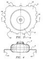
- Figs. 3 and 4 show a top view and a cross-sectional view, respectively, of the gas generator support 4 and gas generator 2 according to the above-described embodiment.
- the gas generator support 4 has an essentially rectangular shape with two flattened corners, however, depending on the place of installation the gas generator support can have any suitable shape, e.g. rectangular like in Fig. 1, without changing its mode of operation.
- L-shaped hooks 16 are formed at the periphery of the gas generator support to extend through the corresponding passageways of the airbag.
- the gas generator support is advantageously made of a metallic sheet allowing to be welded to the gas generator; however, it can alternatively be made of plastic.
- the embodiment of the invention shown in Fig. 5 corresponds to the embodiment illustrated in Fig. 1.
- the sealing shield 18 has a passage 20 through which the gas generator 2 extends at least partially into the interior of the airbag 6.
- sealing shield 18 covers the fastening areas with passageways 14 and the area of gas generator support 4.
- sealing shield 18 The sealing function of sealing shield 18 is illustrated in Fig. 6. Gas inflating the airbag and pressing against the sealing shield 18 is indicated by the arrows in Fig. 6.
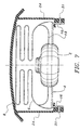
- Fig. 7 shows an alternative embodiment of the invention, wherein the cover 8 is secured to the gas generator support 4 by means of rivets 31.
- the gas generator support is provided with hooks 16 at its outer periphery extending through passageways in the airbag 6.
- the sidewalls 24 of cover 8 are provided with a portion 29 bent toward the inside, in which passageways 26 for receiving the hooks 16 are provided for attaching the cover 8.
- the sidewalls 24 of cover 8 are extended over the bent portion 29 so that a portion is parallel to hooks 16.
- the portion of the sidewalls that contacts the hooks 16 is connected to the hooks by means of rivets 31.
- the cover is additionally secured to the gas generator support. It is thereby no longer possible for the cover to become unintentionally detached from the gas generator support, for example, during transport or assembly. Since the airbag is already securely fastened to the gas generator support by means of the cover, the complete mounted airbag module is securely held together.
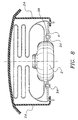
- Fig. 8 shows a modification of the embodiment shown in Fig. 5.
- the gas generator support 4 is not welded to the gas generator 2, but is fastened by means of nuts and bolts 34.
- gas generator 2 is provided with a fastening flange 36 at its periphery which is contacted by the ring-shaped gas generator support 4.
- the fastening flange 36 is firmly connected to the gas generator support 4 by means of nuts and bolts 34.
- other suitable fastening method can be used for connecting the fastening flange 36 with the gas generator support, for instance by rivets.
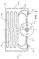
- Fig. 9 shows, in section, a front seat passenger or side airbag module.
- This airbag module differs from the above-described embodiments primarily through the shape of the gas generator 2.
- the gas generator 2 has a tubular shaped housing with a longitudinal axis which extends parallel to the gas generator support 4 and the face 22 of cover 8.
- the gas generator support is welded to the gas generator and has bent hooks 16 at its outer edges.
- the folded airbag 6 is positioned between the gas generator support 4, including the gas generator 2, and the cover 8 which completely encloses the airbag 6 with its sidewalls 24.
- a sealing shield 18 is provided in the interior of the airbag 6, as was explained with reference to Figs. 5 and 6.
- Fig. 10 shows a further embodiment of a front seat passenger or side airbag module.
- Said airbag module substantially corresponds to the airbag module shown in Fig. 9.
- the gas generator support 4 is not welded to the gas generator 2, but is connected thereto by means of nuts and bolts 34.
- the gas generator is provided with a fastening flange 36.
- Fig. 11 shows another embodiment of the invention, wherein the airbag 6 is not fastened to the gas generator support 4, but rather to the cover 8.
- the gas generator support 4 is basically configured as is shown in the embodiment according to Fig. 1.
- the gas generator support 4 is substantially rectangular and the round, cylindrical gas generator 2 is situated approximately in the center thereof.
- the gas generator support extends around the gas generator and is welded to gas generator.
- Essentially perpendicularly bent hooks 16 are provided spaced from each other at the outer periphery of the gas generator support 4.
- the hooks 16 are advantageously made integrally with the gas generator support 4 by means of forming, for example from sheet metal.
- the cover 8 is provided with a cover plate 22, which, for example in a driver's airbag module, forms the outer cover of the steering wheel.
- the cover 8 has sidewalls 24 in the form of an essentially rectangular frame.
- the sidewalls are integrally made with the cover plate, for example, by means of injection molding.
- the cover can also be composed of several parts or be produced through multiple component injection molding.
- reinforcing ribs 37 are provided in the connection area between cover plate 22 and sidewalls 24.
- the sidewalls 24 are provided with hooks 38 spaced from each other, which are bent towards the outside perpendicularly in an L-shape manner. Said hooks 38 can extend through the passageways 14 of the airbag 6, which substantially correspond to the embodiment shown in Fig. 1.
- passageways 40 are provided in the sidewalls 24 of the cover 8 through which the corresponding hooks 16 of the gas generator support 4 can extend.
- the hooks 38 of the cover 8 extend through the passageways 14 of the airbag 6.
- the cover with the airbag fastened thereto is connected with the gas generator support 4.
- the hooks 16 of the gas generator support 4 are equally guided through the passageways 14 in the airbag and through the passageways 40 in the sidewalls of cover 8. This additionally secures the airbag 6 to the cover 8, since it cannot become detached from hooks 38 as long as the gas generator support 4 extends through the passageways 40 in cover 8.
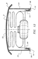
- Fig. 12 shows a further embodiment of the inventive airbag module.
- This embodiment has a cover 8 with hooks 38 formed at the edges of its sidewalls 24, like in Fig. 11, which extend through the passageways 14 of the airbag 6. Additionally, the sidewalls 24 are provided with U-shaped hooks 44 directed towards the inside at their end remote of the cover plate 22. The hooks of the gas generator support are hooked into said hooks 44. The hooks of the gas generator support thereby extend through passageways in the airbag 6 so that the fastening thereof to the cover 8 is additionally secured.
- FIG. 13 Another embodiment of the airbag module is illustrated in Fig. 13.
- the gas generator 2 corresponds essentially to the gas generators of the above-described driver's airbag modules.
- the flat gas generator support 4 extends from the periphery of the gas generator 2.
- the gas generator support 4 is provided with passageways 46 near its outer edges.
- the sidewalls 24 of the cover 8 have hooks 48 which are bent essentially perpendicularly towards the outside at their end opposite the cover plate 22. Said hooks 48 extend through the corresponding passageways 46 in the gas generator support 4.
- the folded airbag 6 is arranged between the cover plate 22 and the gas generator 4, wherein it is enclosed by the sidewalls 24 of the cover 8, and is provided with passageways 14 near the periphery of the opening 10.
- Said passageways 14 are hooked into the hooks 48 of cover 8 so that the airbag 6 is securely retained at cover 8.
- the airbag 6 is first hooked into the hooks 48 of cover 8 prior to engaging the hooks 48 in the passageways 46 through the gas generator support 4. This secures the airbag 6 to the cover 8 by means of the gas generator support 4. An unintended detachment of airbag 6 from cover 8 is thus not possible as long as the gas generator support 4 engages the hooks 48 of cover 8 via its passageways 46.
- a sealing shield 18 is provided in the interior of the airbag 6, as is explained in the preceding embodiments.
Landscapes
- Engineering & Computer Science (AREA)
- Mechanical Engineering (AREA)
- Chemical & Material Sciences (AREA)
- Combustion & Propulsion (AREA)
- Transportation (AREA)
- Air Bags (AREA)
Description
Claims (8)
- Airbag module comprising:a gas generator (2),a gas generator support (4) connected with the gas generator (2),a cover (8) connected with the gas generator support (4), andan airbag (6), which is arranged in a folded state between the gas generator support (4) and the cover (8), said airbag having an opening (10) therein in which the gas generator (2) and the gas generator support (4) is installed, and with passageways (14) near the periphery of said opening (10) through which hooks (16, 38) of the gas generator support (4) and/or the cover (8) extend, characterised in that a sealing shield (18) is fastened to the inside of the airbag, said sealing shield (18) closes the opening (10) in the airbag (6) except for one passage (20), through which a part of the gas generator extends into the interior of the airbag, and wherein the sealing shield is pressed against the gas generator support and/or the gas generator by inflation gas from the gas generator for sealing the airbag.
- An airbag module according to claim 1, wherein the airbag (6) and the cover (8) are fastened by the hooks (16) of the gas generator support (4).
- An airbag module according to claim 1 or 2, wherein the fastening of the airbag (6) to the gas generator support (4) is secured by the cover (8).
- An airbag module according to claim 1, wherein the airbag (6) and the gas generator support (4) are fastened by the hooks (38) of the cover (8).
- An airbag module according to one of claims 1 or 4, wherein the fastening of the airbag (6) to the cover (8) is secured by the gas generator support (4).
- Airbag module according to one of the preceding claims, wherein the cover (8) is secured to the gas generator support (4) by additional connecting elements (31), particularly by bolts or rivets.
- An airbag module according to one of the preceding claims, wherein the gas generator (2) is integrally formed with the gas generator support (4) or is screwed, clamped, welded or glued to the gas generator support (4).
- An airbag module according to one of the preceding claims, wherein the cover (8) and/or the airbag (6) are further secured by bending the hooks (16, 38).
Applications Claiming Priority (3)
| Application Number | Priority Date | Filing Date | Title |
|---|---|---|---|
| DE19804579 | 1998-02-05 | ||
| DE19804579A DE19804579C2 (en) | 1998-02-05 | 1998-02-05 | Airbag module |
| PCT/US1999/000080 WO1999039942A1 (en) | 1998-02-05 | 1999-01-05 | Airbag module |
Publications (2)
| Publication Number | Publication Date |
|---|---|
| EP1045776A1 EP1045776A1 (en) | 2000-10-25 |
| EP1045776B1 true EP1045776B1 (en) | 2003-03-26 |
Family
ID=7856747
Family Applications (1)
| Application Number | Title | Priority Date | Filing Date |
|---|---|---|---|
| EP99901292A Expired - Lifetime EP1045776B1 (en) | 1998-02-05 | 1999-01-05 | Airbag module |
Country Status (6)
| Country | Link |
|---|---|
| US (1) | US6092834A (en) |
| EP (1) | EP1045776B1 (en) |
| JP (1) | JP2002504449A (en) |
| KR (1) | KR100493796B1 (en) |
| DE (2) | DE19804579C2 (en) |
| WO (1) | WO1999039942A1 (en) |
Cited By (1)
| Publication number | Priority date | Publication date | Assignee | Title |
|---|---|---|---|---|
| DE102015002415A1 (en) | 2015-02-26 | 2016-09-01 | Autoliv Development Ab | airbag module |
Families Citing this family (12)
| Publication number | Priority date | Publication date | Assignee | Title |
|---|---|---|---|---|
| DE19940360B4 (en) * | 1999-08-25 | 2005-12-15 | Autoliv Development Ab | Airbag with a reinforcing layer designed as a diffuser and cover |
| DE29917645U1 (en) | 1999-10-06 | 2000-02-17 | TRW Occupant Restraint Systems GmbH & Co. KG, 73553 Alfdorf | Airbag module |
| DE20104044U1 (en) * | 2001-03-08 | 2001-07-12 | TRW Automotive Safety Systems GmbH & Co. KG, 63743 Aschaffenburg | Airbag module |
| DE20106695U1 (en) | 2001-04-18 | 2001-08-23 | TRW Automotive Safety Systems GmbH & Co. KG, 63743 Aschaffenburg | Airbag module |
| DE20113806U1 (en) * | 2001-08-21 | 2002-02-28 | Breed Automotive Technology, Inc., Lakeland, Fla. | Airbag module with snap connection |
| US6752415B2 (en) | 2001-10-05 | 2004-06-22 | Autoliv Asp, Inc. | Airbag module Z-height control tab |
| DE102006013990A1 (en) | 2006-03-22 | 2007-09-27 | Takata-Petri Ag | Fastening arrangement in an airbag module |
| DE202007007885U1 (en) * | 2007-06-04 | 2007-08-30 | Takata-Petri Ag | Airbag attachment in an airbag module |
| JP4890391B2 (en) * | 2007-08-24 | 2012-03-07 | 本田技研工業株式会社 | Airbag device |
| DE102010047090A1 (en) * | 2010-10-01 | 2012-04-05 | Autoliv Development Ab | Airbag module for a motor vehicle |
| DE102012200148A1 (en) * | 2012-01-05 | 2013-07-11 | TAKATA Aktiengesellschaft | Airbag module |
| JP6162476B2 (en) * | 2013-05-13 | 2017-07-12 | 芦森工業株式会社 | Airbag device |
Family Cites Families (21)
| Publication number | Priority date | Publication date | Assignee | Title |
|---|---|---|---|---|
| US4810005A (en) * | 1986-07-22 | 1989-03-07 | Trw Repa Gmbh | Gas cushion impact protection device for motor vehicles |
| JPH0534285Y2 (en) * | 1987-02-05 | 1993-08-31 | ||
| JPS6460756A (en) * | 1987-08-28 | 1989-03-07 | Fuji Heavy Ind Ltd | Start controller for engine |
| US4913461A (en) * | 1988-12-27 | 1990-04-03 | Talley Automotive Products, Inc. | Airbag module and method of making same |
| US5074584A (en) * | 1990-06-20 | 1991-12-24 | Trw Vehicle Safety Systems Inc. | Air bag fastener |
| US5186492A (en) * | 1991-08-08 | 1993-02-16 | Trw Vehicle Safety Systems, Inc. | Air bag module |
| CA2079025A1 (en) * | 1991-10-17 | 1993-04-18 | Paul E. Strahl | Air bag cushion rivetless retainer ring, axial pin methd |
| JP3082460B2 (en) * | 1992-08-31 | 2000-08-28 | タカタ株式会社 | Airbag device |
| GB2270882B (en) * | 1992-09-28 | 1996-05-08 | Autoliv Dev | Improvements in or relating to an air-bag arrangement |
| JPH0644652U (en) * | 1992-11-27 | 1994-06-14 | 豊田合成株式会社 | Airbag device |
| US5320379A (en) * | 1993-05-05 | 1994-06-14 | Automotive Systems Laboratory, Inc. | Inflator mounting system |
| DE4425495A1 (en) * | 1994-07-19 | 1996-01-25 | Takata Europ Gmbh | Airbag unit for vehicle |
| DE4425328A1 (en) * | 1994-07-18 | 1996-01-25 | Takata Europ Gmbh | Airbag fitting for vehicle |
| US5658008A (en) * | 1994-07-19 | 1997-08-19 | Takata (Europe) Vehicle Safety Technology Gmbh | Airbag arrangement |
| US5542692A (en) * | 1994-10-18 | 1996-08-06 | Morton International, Inc. | Inflatable cushion assembly and system |
| US5520411A (en) * | 1995-03-23 | 1996-05-28 | Morton International, Inc. | Cover mounting for an airbag assembly |
| JP3651068B2 (en) * | 1995-07-31 | 2005-05-25 | 豊田合成株式会社 | Airbag device |
| US5607179A (en) * | 1995-10-04 | 1997-03-04 | General Motors Corporation | Deformable air bag retainer |
| US5709401A (en) * | 1995-10-26 | 1998-01-20 | General Motors Corporation | Air bag attachment to module |
| US5683100A (en) * | 1996-07-12 | 1997-11-04 | Morton International, Inc. | Airbag cushion retainer with annular sewing area |
| US5709402A (en) * | 1996-07-29 | 1998-01-20 | Morton International, Inc. | Attachment fingers for airbag module cover |
-
1998
- 1998-02-05 DE DE19804579A patent/DE19804579C2/en not_active Expired - Fee Related
-
1999
- 1999-01-05 DE DE69906250T patent/DE69906250D1/en not_active Expired - Lifetime
- 1999-01-05 US US09/226,090 patent/US6092834A/en not_active Expired - Lifetime
- 1999-01-05 KR KR10-2000-7008434A patent/KR100493796B1/en not_active Expired - Fee Related
- 1999-01-05 EP EP99901292A patent/EP1045776B1/en not_active Expired - Lifetime
- 1999-01-05 JP JP2000530396A patent/JP2002504449A/en not_active Withdrawn
- 1999-01-05 WO PCT/US1999/000080 patent/WO1999039942A1/en not_active Ceased
Cited By (2)
| Publication number | Priority date | Publication date | Assignee | Title |
|---|---|---|---|---|
| DE102015002415A1 (en) | 2015-02-26 | 2016-09-01 | Autoliv Development Ab | airbag module |
| DE102015002415B4 (en) | 2015-02-26 | 2018-03-01 | Autoliv Development Ab | airbag module |
Also Published As
| Publication number | Publication date |
|---|---|
| DE19804579A1 (en) | 1999-08-19 |
| DE69906250D1 (en) | 2003-04-30 |
| JP2002504449A (en) | 2002-02-12 |
| WO1999039942A1 (en) | 1999-08-12 |
| US6092834A (en) | 2000-07-25 |
| KR100493796B1 (en) | 2005-06-08 |
| KR20010040565A (en) | 2001-05-15 |
| EP1045776A1 (en) | 2000-10-25 |
| DE19804579C2 (en) | 2001-12-06 |
Similar Documents
| Publication | Publication Date | Title |
|---|---|---|
| US6092834A (en) | Airbag module | |
| JP2523406B2 (en) | Airbag assembly | |
| EP0469734B1 (en) | Air cushion restraint device having reinforced inflation attachment | |
| JP2721719B2 (en) | Airbag module and its assembly method | |
| US20070252365A1 (en) | Air bag | |
| EP0622277A1 (en) | Air bag module with a center mounted tubular inflator | |
| US20030234525A1 (en) | Airbag apparatus | |
| US5121941A (en) | Air bag module | |
| US5246249A (en) | Air bag unit | |
| US5366240A (en) | Air bag device including a two piece casing | |
| US5762360A (en) | Air bag assembly | |
| JPH04201756A (en) | Air bag mounting structure for air bag device | |
| US5997036A (en) | Air bag device and method of producing same | |
| US6092833A (en) | Air bag mounting structure for passenger-side air bag device | |
| US7083185B2 (en) | Housing for motor vehicle airbag | |
| WO1997024241A1 (en) | Attachment device for an inflatable protective cushion | |
| US5509685A (en) | Air bag module | |
| US5779261A (en) | Vehicle air bag retaining arrangement | |
| US5709401A (en) | Air bag attachment to module | |
| JP2583742B2 (en) | Method and apparatus for retaining a cushion of an airbag | |
| US20030038459A1 (en) | Gas generator for an airbag on the steering wheel of a motor vehicle | |
| GB2268124A (en) | An air-bag arrangement | |
| US5295706A (en) | Air bag | |
| US5308109A (en) | Air bag device for a passenger | |
| EP0943500B1 (en) | Air bag mounting structure for passenger-side air bag device |
Legal Events
| Date | Code | Title | Description |
|---|---|---|---|
| PUAI | Public reference made under article 153(3) epc to a published international application that has entered the european phase |
Free format text: ORIGINAL CODE: 0009012 |
|
| 17P | Request for examination filed |
Effective date: 20000608 |
|
| AK | Designated contracting states |
Kind code of ref document: A1 Designated state(s): DE ES FR GB IT |
|
| GRAG | Despatch of communication of intention to grant |
Free format text: ORIGINAL CODE: EPIDOS AGRA |
|
| GRAG | Despatch of communication of intention to grant |
Free format text: ORIGINAL CODE: EPIDOS AGRA |
|
| GRAH | Despatch of communication of intention to grant a patent |
Free format text: ORIGINAL CODE: EPIDOS IGRA |
|
| 17Q | First examination report despatched |
Effective date: 20020605 |
|
| GRAH | Despatch of communication of intention to grant a patent |
Free format text: ORIGINAL CODE: EPIDOS IGRA |
|
| GRAA | (expected) grant |
Free format text: ORIGINAL CODE: 0009210 |
|
| AK | Designated contracting states |
Designated state(s): DE ES FR GB IT |
|
| REG | Reference to a national code |
Ref country code: GB Ref legal event code: FG4D |
|
| REF | Corresponds to: |
Ref document number: 69906250 Country of ref document: DE Date of ref document: 20030430 Kind code of ref document: P |
|
| PG25 | Lapsed in a contracting state [announced via postgrant information from national office to epo] |
Ref country code: DE Free format text: LAPSE BECAUSE OF FAILURE TO SUBMIT A TRANSLATION OF THE DESCRIPTION OR TO PAY THE FEE WITHIN THE PRESCRIBED TIME-LIMIT Effective date: 20030627 |
|
| PG25 | Lapsed in a contracting state [announced via postgrant information from national office to epo] |
Ref country code: ES Free format text: LAPSE BECAUSE OF FAILURE TO SUBMIT A TRANSLATION OF THE DESCRIPTION OR TO PAY THE FEE WITHIN THE PRESCRIBED TIME-LIMIT Effective date: 20030930 |
|
| ET | Fr: translation filed | ||
| PLBE | No opposition filed within time limit |
Free format text: ORIGINAL CODE: 0009261 |
|
| STAA | Information on the status of an ep patent application or granted ep patent |
Free format text: STATUS: NO OPPOSITION FILED WITHIN TIME LIMIT |
|
| 26N | No opposition filed |
Effective date: 20031230 |
|
| REG | Reference to a national code |
Ref country code: GB Ref legal event code: 732E |
|
| REG | Reference to a national code |
Ref country code: FR Ref legal event code: TP |
|
| PGFP | Annual fee paid to national office [announced via postgrant information from national office to epo] |
Ref country code: IT Payment date: 20090115 Year of fee payment: 11 |
|
| PGFP | Annual fee paid to national office [announced via postgrant information from national office to epo] |
Ref country code: FR Payment date: 20090106 Year of fee payment: 11 |
|
| PGFP | Annual fee paid to national office [announced via postgrant information from national office to epo] |
Ref country code: GB Payment date: 20091211 Year of fee payment: 12 |
|
| REG | Reference to a national code |
Ref country code: FR Ref legal event code: ST Effective date: 20100930 |
|
| PG25 | Lapsed in a contracting state [announced via postgrant information from national office to epo] |
Ref country code: FR Free format text: LAPSE BECAUSE OF NON-PAYMENT OF DUE FEES Effective date: 20100201 |
|
| PG25 | Lapsed in a contracting state [announced via postgrant information from national office to epo] |
Ref country code: IT Free format text: LAPSE BECAUSE OF NON-PAYMENT OF DUE FEES Effective date: 20100105 |
|
| GBPC | Gb: european patent ceased through non-payment of renewal fee |
Effective date: 20110105 |
|
| PG25 | Lapsed in a contracting state [announced via postgrant information from national office to epo] |
Ref country code: GB Free format text: LAPSE BECAUSE OF NON-PAYMENT OF DUE FEES Effective date: 20110105 |