EP1045471A1 - Radar mounting structure using resin including bubbles - Google Patents
Radar mounting structure using resin including bubbles Download PDFInfo
- Publication number
- EP1045471A1 EP1045471A1 EP00303172A EP00303172A EP1045471A1 EP 1045471 A1 EP1045471 A1 EP 1045471A1 EP 00303172 A EP00303172 A EP 00303172A EP 00303172 A EP00303172 A EP 00303172A EP 1045471 A1 EP1045471 A1 EP 1045471A1
- Authority
- EP
- European Patent Office
- Prior art keywords
- front grille
- radar
- bubbles
- vehicle
- mounting structure
- Prior art date
- Legal status (The legal status is an assumption and is not a legal conclusion. Google has not performed a legal analysis and makes no representation as to the accuracy of the status listed.)
- Withdrawn
Links
- 239000011347 resin Substances 0.000 title claims abstract description 23
- 229920005989 resin Polymers 0.000 title claims abstract description 23
- 239000000463 material Substances 0.000 abstract description 11
- 238000002834 transmittance Methods 0.000 abstract description 6
- 238000010586 diagram Methods 0.000 description 2
- 238000000034 method Methods 0.000 description 2
- 238000007796 conventional method Methods 0.000 description 1
Images


Classifications
-
- H—ELECTRICITY
- H01—ELECTRIC ELEMENTS
- H01Q—ANTENNAS, i.e. RADIO AERIALS
- H01Q1/00—Details of, or arrangements associated with, antennas
- H01Q1/27—Adaptation for use in or on movable bodies
- H01Q1/32—Adaptation for use in or on road or rail vehicles
- H01Q1/3208—Adaptation for use in or on road or rail vehicles characterised by the application wherein the antenna is used
- H01Q1/3233—Adaptation for use in or on road or rail vehicles characterised by the application wherein the antenna is used particular used as part of a sensor or in a security system, e.g. for automotive radar, navigation systems
-
- B—PERFORMING OPERATIONS; TRANSPORTING
- B60—VEHICLES IN GENERAL
- B60R—VEHICLES, VEHICLE FITTINGS, OR VEHICLE PARTS, NOT OTHERWISE PROVIDED FOR
- B60R11/00—Arrangements for holding or mounting articles, not otherwise provided for
-
- H—ELECTRICITY
- H01—ELECTRIC ELEMENTS
- H01Q—ANTENNAS, i.e. RADIO AERIALS
- H01Q1/00—Details of, or arrangements associated with, antennas
- H01Q1/42—Housings not intimately mechanically associated with radiating elements, e.g. radome
Definitions
- the present invention relates to a radar mounting structure used for mounting a radar in a vehicle.
- the radar when a radar is mounted in a vehicle so as to detect an obstacle in front of the vehicle or to measure a distance to a vehicle ahead of the present vehicle, the radar may be mounted inside a front grille so as to maintain a desirable external appearance.
- Figs. 5 and 6 are diagrams for explaining a conventional method for mounting a radar inside the front grille.
- reference numeral 1 indicates a front grille.
- a center area of the front grille, facing radar 3, is opened and plate 5' is attached to the open area.
- This plate 5' is made of a material having a high radio-wave transmittance, and the plate also functions as an emblem. The radio-wave transmitting and receiving operations are performed through the plate 5'.
- the above method is employed for detecting an object using the radar mounted inside the front grille, but the structure and material of the front grille are limited in this method. As a result, design flexibility and processing efficiency are degraded.
- an objective of the present invention is to provide a radar mounting structure in which a radar is mounted inside a front grille through which a radio wave is transmitted and received, by which the structure, shape, and material of the front grille are not limited, and the front grille can be easily processed.
- the present invention provides a radar mounting structure for mounting a radar in a vehicle, comprising a front grille made of a resin including bubbles, wherein the radar is mounted in the vehicle so as to transmit and receive radio waves through the front grille.
- the structure may further comprise an emblem made of a resin including bubbles, which is overlapped over the front grille so as to transmit and receive the radio wave through the front grille and the emblem.
- the present invention provides a radar mounting structure for mounting a radar in a vehicle, comprising a front grille having an open area; and a plate made of a resin including bubbles, attached to the open area of the front grille, and wherein the radar is mounted in the vehicle so as to transmit and receive radio waves through the plate.
- the attenuation of the radio wave can be suppressed by the bubbles, thereby transmitting and receiving the radio waves with sufficient radio-wave transmittance.
- the structure, shape, and material of the front grille portion are not limited.
- Fig. 1 is a side view of an embodiment of the radar mounting structure according to the present invention.
- Fig. 2 is a front view of the front grille portion of the embodiment.
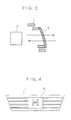
- Fig. 3 is a side view of another embodiment of the radar mounting structure according to the present invention.
- Fig. 4 is a front view of the front grille portion of the embodiment of Fig. 3.
- Fig. 5 is a side view of a conventional radar mounting structure.
- Fig. 6 is a front view of the front grille portion of the conventional structure.
- Figs. 1 and 2 are diagrams showing an embodiment of the radar mounting structure of the present invention.
- the embodiment relates to a general mounting structure in which emblem 2 is overlapped over a center area of front grille 1, and radar 3 is mounted inside the front grille 1.
- the front grille 1 and emblem 2 are made of resin 4 including bubbles and the amount of said bubbles is determined according to the desired attenuation of the radio waves.
- Radar 3 is provided in a center portion of the vehicle so as to detect an obstacle in front of the vehicle or to measure a distance to a vehicle ahead of the present vehicle, under the most optimal conditions.
- the bubbles included therein minimize the attenuation of the radio waves.
- Resin 4 including bubbles may be a foamed resin, or a hollow or honeycomb resin.
- the radio-wave transmitting and receiving operations can be performed with a sufficient radio-wave transmittance, regardless of the shape of the portion including the front grille 1 and emblem 2.
- the material of resin 4 itself (in which bubbles are not included) is not limited, that is, even a resin originally having insufficient radio-wave transmittance can be employed; thus, the flexibility for selecting a material can be improved, for example, weather-resistant or unfading materials, or various colored materials may be used.
- the emblem 2 may not be attached to the front grille 1, and in this case, the radio wave is transmitted or received by radar 3 only through the front grille 1.
- Figs. 3 and 4 show another embodiment according to the present invention.
- a center area of the front grille 1, facing radar 3, is opened and plate 5 is attached to the open area.
- This plate 5 is made of resin 4 including bubbles, and the plate also functions as an emblem. The radio-wave transmitting and receiving operations are performed through the plate 5.
- plate 5 may be separately attached to front grille 1, or the front grille 1 and plate 5 may be integrally formed using resin 4 including bubbles.
Landscapes
- Engineering & Computer Science (AREA)
- Computer Security & Cryptography (AREA)
- Radar, Positioning & Navigation (AREA)
- Remote Sensing (AREA)
- Mechanical Engineering (AREA)
- Radar Systems Or Details Thereof (AREA)
Abstract
A radar mounting structure in which a radar is
mounted inside a front grille through which a radio wave
is transmitted and received with a sufficient radio-wave
transmittance is disclosed, by which the structure,
shape, and material of the front grille are not limited,
and the front grille can be easily processed. The
structure comprises a front grille (1) made of a resin
(4) including bubbles, wherein the radar (3) is mounted
in the vehicle so as to transmit and receive radio waves
through the front grille. The amount of said bubbles is
determined according to the desired attenuation of the
radio waves.
Description
- The present invention relates to a radar mounting structure used for mounting a radar in a vehicle.
- This application is based on Patent Application No. Hei 11-147030 filed in Japan, the contents of which are incorporated herein by reference.
- Generally, when a radar is mounted in a vehicle so as to detect an obstacle in front of the vehicle or to measure a distance to a vehicle ahead of the present vehicle, the radar may be mounted inside a front grille so as to maintain a desirable external appearance.
- Figs. 5 and 6 are diagrams for explaining a conventional method for mounting a radar inside the front grille. In the figures,
reference numeral 1 indicates a front grille. Here, a center area of the front grille, facingradar 3, is opened and plate 5' is attached to the open area. This plate 5' is made of a material having a high radio-wave transmittance, and the plate also functions as an emblem. The radio-wave transmitting and receiving operations are performed through the plate 5'. - The above method is employed for detecting an object using the radar mounted inside the front grille, but the structure and material of the front grille are limited in this method. As a result, design flexibility and processing efficiency are degraded.
- In consideration of the above circumstances, an objective of the present invention, at least in a preferred embodiment, is to provide a radar mounting structure in which a radar is mounted inside a front grille through which a radio wave is transmitted and received, by which the structure, shape, and material of the front grille are not limited, and the front grille can be easily processed.
- Therefore, viewed from a first aspect, the present invention provides a radar mounting structure for mounting a radar in a vehicle, comprising a front grille made of a resin including bubbles, wherein the radar is mounted in the vehicle so as to transmit and receive radio waves through the front grille.
- The structure may further comprise an emblem made of a resin including bubbles, which is overlapped over the front grille so as to transmit and receive the radio wave through the front grille and the emblem.
- Viewed from another aspect, the present invention provides a radar mounting structure for mounting a radar in a vehicle, comprising a front grille having an open area; and a plate made of a resin including bubbles, attached to the open area of the front grille, and wherein the radar is mounted in the vehicle so as to transmit and receive radio waves through the plate.
- Accordingly, the attenuation of the radio wave can be suppressed by the bubbles, thereby transmitting and receiving the radio waves with sufficient radio-wave transmittance. In addition, the structure, shape, and material of the front grille portion are not limited.
- Some preferred embodiments of the present invention will now be described, by way of example only, and with reference to the accompanying drawings in which:
- Fig. 1 is a side view of an embodiment of the radar mounting structure according to the present invention.
- Fig. 2 is a front view of the front grille portion of the embodiment.
- Fig. 3 is a side view of another embodiment of the radar mounting structure according to the present invention.
- Fig. 4 is a front view of the front grille portion of the embodiment of Fig. 3.
- Fig. 5 is a side view of a conventional radar mounting structure.
- Fig. 6 is a front view of the front grille portion of the conventional structure.
- Hereinafter, embodiments according to the present invention will be explained with reference to the drawings.
- Figs. 1 and 2 are diagrams showing an embodiment of the radar mounting structure of the present invention. The embodiment relates to a general mounting structure in which
emblem 2 is overlapped over a center area offront grille 1, andradar 3 is mounted inside thefront grille 1. Here, thefront grille 1 andemblem 2 are made ofresin 4 including bubbles and the amount of said bubbles is determined according to the desired attenuation of the radio waves. -
Radar 3 is provided in a center portion of the vehicle so as to detect an obstacle in front of the vehicle or to measure a distance to a vehicle ahead of the present vehicle, under the most optimal conditions. - According to the above structure, when the radio wave is transmitted or received through the
front grille 1 andemblem 2, the bubbles included therein minimize the attenuation of the radio waves. -
Resin 4 including bubbles may be a foamed resin, or a hollow or honeycomb resin. - Therefore, by merely forming the
front grille 1 andemblem 2 usingresin 4 including bubbles, the radio-wave transmitting and receiving operations can be performed with a sufficient radio-wave transmittance, regardless of the shape of the portion including thefront grille 1 andemblem 2. - The material of
resin 4 itself (in which bubbles are not included) is not limited, that is, even a resin originally having insufficient radio-wave transmittance can be employed; thus, the flexibility for selecting a material can be improved, for example, weather-resistant or unfading materials, or various colored materials may be used. - The
emblem 2 may not be attached to thefront grille 1, and in this case, the radio wave is transmitted or received byradar 3 only through thefront grille 1. - Figs. 3 and 4 show another embodiment according to the present invention.
- In this case, a center area of the
front grille 1, facingradar 3, is opened andplate 5 is attached to the open area. Thisplate 5 is made ofresin 4 including bubbles, and the plate also functions as an emblem. The radio-wave transmitting and receiving operations are performed through theplate 5. - According to this structure, it is unnecessary to form the
plate 5 by using a material having a high radio-wave transmittance; thus, the flexibility for selecting a material can be improved. In addition,plate 5 may be separately attached tofront grille 1, or thefront grille 1 andplate 5 may be integrally formed usingresin 4 including bubbles.
Claims (7)
- A radar mounting structure for mounting a radar (3) in a vehicle, characterized by comprising a front grille (1) made of a resin (4) including bubbles, wherein the radar is mounted in the vehicle so as to transmit and receive radio waves through the front grille.
- A radar mounting structure as claimed in claim 1, characterized by further comprising an emblem (2) made of a resin (4) including bubbles, which is overlapped over the front grille so as to transmit and receive the radio waves through the front grille and the emblem.
- A radar mounting structure for mounting a radar (3) in a vehicle, characterized by comprising:a front grille (1) having an open area; anda plate (5) made of a resin including bubbles, attached to the open area of the front grille, andwherein the radar is mounted in the vehicle so as to transmit and receive radio waves through the plate.
- A radar mounting structure as claimed in any one of claims 1 to 3, wherein the amount of said bubbles is determined according to the desired attenuation of the radio waves.
- A radar mounting structure for mounting a radar (3) in a vehicle, comprising a front grille (1) made of a resin (4) including a large number of bubbles, wherein the radar is mounted in the vehicle so as to transmit and receive radio waves through the front grille and said bubbles minimize the attenuation of the radio waves as they pass through the resin forming the front grille.
- A radar mounting structure as claimed in claim 5, wherein an emblem (2) made of a resin (4) including a large number of bubbles is overlapped over the front grille and the radio waves are transmitted and received through the front grille and the emblem, and said bubbles minimize the attenuation of the radio waves as they pass through the resin forming the front grille and the emblem.
- A radar mounting structure for mounting a radar (3) in a vehicle, comprising:a front grille (1) having an open area;a plate (5) made of a resin (4) including a large number of bubbles, attached to the open area of the front grille;wherein the radar is mounted in the vehicle so as to transmit and receive radio waves through the plate; andsaid bubbles minimize the attenuation of the radio waves as they pass through the resin forming the plate.
Applications Claiming Priority (2)
| Application Number | Priority Date | Filing Date | Title |
|---|---|---|---|
| JP14703099 | 1999-04-16 | ||
| JP11147030A JP2000304847A (en) | 1999-04-16 | 1999-04-16 | Radar on-board structure |
Publications (1)
| Publication Number | Publication Date |
|---|---|
| EP1045471A1 true EP1045471A1 (en) | 2000-10-18 |
Family
ID=15420959
Family Applications (1)
| Application Number | Title | Priority Date | Filing Date |
|---|---|---|---|
| EP00303172A Withdrawn EP1045471A1 (en) | 1999-04-16 | 2000-04-14 | Radar mounting structure using resin including bubbles |
Country Status (2)
| Country | Link |
|---|---|
| EP (1) | EP1045471A1 (en) |
| JP (1) | JP2000304847A (en) |
Cited By (5)
| Publication number | Priority date | Publication date | Assignee | Title |
|---|---|---|---|---|
| EP0954052A3 (en) * | 1998-05-02 | 2002-09-04 | DaimlerChrysler AG | Fabrication method for a radome of a distance measurement radar |
| FR2827080A1 (en) * | 2001-07-06 | 2003-01-10 | Thales Sa | DEVICE FOR HIDING A RADAR REPRESENTING A VOLUME PATTERN, ESPECIALLY EQUIPPED WITH A VEHICLE AND DETECTION SYSTEM COMPRISING SUCH A DEVICE |
| US9828036B2 (en) | 2015-11-24 | 2017-11-28 | Srg Global Inc. | Active grille shutter system with integrated radar |
| US20170364086A1 (en) * | 2016-06-17 | 2017-12-21 | Toyota Motor Engineering & Manufacturing North America, Inc. | Sensor integration into existing vehicle structures |
| US20200358174A1 (en) * | 2017-12-28 | 2020-11-12 | Srg Global, Inc. | Microcellular foam body component for a vehicle radar system and its methods of manufacture |
Families Citing this family (6)
| Publication number | Priority date | Publication date | Assignee | Title |
|---|---|---|---|---|
| JP3958970B2 (en) * | 2002-01-08 | 2007-08-15 | 本田技研工業株式会社 | Mobile radar system |
| JP4821535B2 (en) * | 2006-09-25 | 2011-11-24 | トヨタ自動車株式会社 | Front grill |
| JP2009031284A (en) * | 2008-07-22 | 2009-02-12 | Toyota Motor Corp | Vehicle radar device cover |
| JP6552326B2 (en) * | 2015-08-07 | 2019-07-31 | 株式会社東海理化電機製作所 | Radio wave transmission parts |
| JP7063232B2 (en) * | 2018-10-26 | 2022-05-09 | トヨタ自動車株式会社 | Vehicle front structure |
| JP7512937B2 (en) * | 2021-03-26 | 2024-07-09 | 豊田合成株式会社 | Vehicle exterior parts and manufacturing method thereof |
Citations (5)
| Publication number | Priority date | Publication date | Assignee | Title |
|---|---|---|---|---|
| EP0676648A1 (en) * | 1994-04-07 | 1995-10-11 | Murata Manufacturing Co., Ltd. | Transmit-receive module for a means of transportation |
| US5662293A (en) * | 1995-05-05 | 1997-09-02 | Hower; R. Thomas | Polyimide foam-containing radomes |
| DE19712098A1 (en) * | 1997-03-22 | 1998-05-14 | Bosch Gmbh Robert | Vehicle radar sensor |
| EP0954052A2 (en) * | 1998-05-02 | 1999-11-03 | DaimlerChrysler AG | Fabrication method for a radome of a distance measurement radar |
| FR2784235A1 (en) * | 1998-09-25 | 2000-04-07 | Daimler Chrysler Ag | Plastics vehicle fairing component with metallized zones on exterior, e.g. center part of radiator grille, has multilayer structure with deposited thin metal films allowing passage of radar signals |
-
1999
- 1999-04-16 JP JP11147030A patent/JP2000304847A/en active Pending
-
2000
- 2000-04-14 EP EP00303172A patent/EP1045471A1/en not_active Withdrawn
Patent Citations (5)
| Publication number | Priority date | Publication date | Assignee | Title |
|---|---|---|---|---|
| EP0676648A1 (en) * | 1994-04-07 | 1995-10-11 | Murata Manufacturing Co., Ltd. | Transmit-receive module for a means of transportation |
| US5662293A (en) * | 1995-05-05 | 1997-09-02 | Hower; R. Thomas | Polyimide foam-containing radomes |
| DE19712098A1 (en) * | 1997-03-22 | 1998-05-14 | Bosch Gmbh Robert | Vehicle radar sensor |
| EP0954052A2 (en) * | 1998-05-02 | 1999-11-03 | DaimlerChrysler AG | Fabrication method for a radome of a distance measurement radar |
| FR2784235A1 (en) * | 1998-09-25 | 2000-04-07 | Daimler Chrysler Ag | Plastics vehicle fairing component with metallized zones on exterior, e.g. center part of radiator grille, has multilayer structure with deposited thin metal films allowing passage of radar signals |
Cited By (8)
| Publication number | Priority date | Publication date | Assignee | Title |
|---|---|---|---|---|
| EP0954052A3 (en) * | 1998-05-02 | 2002-09-04 | DaimlerChrysler AG | Fabrication method for a radome of a distance measurement radar |
| FR2827080A1 (en) * | 2001-07-06 | 2003-01-10 | Thales Sa | DEVICE FOR HIDING A RADAR REPRESENTING A VOLUME PATTERN, ESPECIALLY EQUIPPED WITH A VEHICLE AND DETECTION SYSTEM COMPRISING SUCH A DEVICE |
| EP1280229A1 (en) * | 2001-07-06 | 2003-01-29 | Thales | Device to hide a radar representing a three-dimensional pattern |
| US9828036B2 (en) | 2015-11-24 | 2017-11-28 | Srg Global Inc. | Active grille shutter system with integrated radar |
| US10137938B2 (en) | 2015-11-24 | 2018-11-27 | Srg Global Inc. | Active grille shutter system with integrated radar |
| US20170364086A1 (en) * | 2016-06-17 | 2017-12-21 | Toyota Motor Engineering & Manufacturing North America, Inc. | Sensor integration into existing vehicle structures |
| US10589694B2 (en) * | 2016-06-17 | 2020-03-17 | Toyota Motor Engineering & Manufacturing North America, Inc. | Sensor integration into existing vehicle structures |
| US20200358174A1 (en) * | 2017-12-28 | 2020-11-12 | Srg Global, Inc. | Microcellular foam body component for a vehicle radar system and its methods of manufacture |
Also Published As
| Publication number | Publication date |
|---|---|
| JP2000304847A (en) | 2000-11-02 |
Similar Documents
| Publication | Publication Date | Title |
|---|---|---|
| EP1045471A1 (en) | Radar mounting structure using resin including bubbles | |
| EP0989028B1 (en) | Vehicle exterior mirror with antenna | |
| US8432309B2 (en) | Automotive radar system and method for using same | |
| US5177494A (en) | Vehicular slot antenna system | |
| US20050237250A1 (en) | Sensor for transmitting and receiving electromagnetic signals | |
| US6433748B1 (en) | Elastic antenna element | |
| JPH11160426A (en) | In-vehicle radar device | |
| EP4174513A1 (en) | Vehicular lamp fitting and radar structure | |
| EP0881624A3 (en) | Ultrasonic sensor and its ultrasonic resonator | |
| EP1032135A3 (en) | Method for reducing interference in a receiver | |
| EP0851527A3 (en) | Vehicle side window glass antenna for radio broadcast waves | |
| JP7473611B2 (en) | Radar device protection structure for vehicle | |
| US9205722B2 (en) | Vehicle window structure | |
| JP2005260659A (en) | Windshield with antenna for vehicle | |
| USD460935S1 (en) | Conversion panels | |
| US6433750B1 (en) | Reception antenna for radio wave marker | |
| JP2005142913A (en) | In-vehicle lens antenna | |
| AU2006302955A1 (en) | On a radome mounted GPS antenna assembly | |
| US6670927B2 (en) | Vehicular glass antenna | |
| US5940042A (en) | Windshield slot antenna for vehicle transmissions | |
| JP6738891B2 (en) | Vehicle including rearview mirror and antenna | |
| JP4821535B2 (en) | Front grill | |
| JP2005104330A (en) | Pneumatic force adder for vehicle | |
| WO2000045192A3 (en) | Receiving device for a radar device and corresponding radar device | |
| EP1095828A3 (en) | Intruder detection system for a motor vehicle |
Legal Events
| Date | Code | Title | Description |
|---|---|---|---|
| PUAI | Public reference made under article 153(3) epc to a published international application that has entered the european phase |
Free format text: ORIGINAL CODE: 0009012 |
|
| AK | Designated contracting states |
Kind code of ref document: A1 Designated state(s): DE FR GB |
|
| AX | Request for extension of the european patent |
Free format text: AL;LT;LV;MK;RO;SI |
|
| 17P | Request for examination filed |
Effective date: 20010117 |
|
| AKX | Designation fees paid |
Free format text: DE FR GB |
|
| 17Q | First examination report despatched |
Effective date: 20020415 |
|
| STAA | Information on the status of an ep patent application or granted ep patent |
Free format text: STATUS: THE APPLICATION IS DEEMED TO BE WITHDRAWN |
|
| 18D | Application deemed to be withdrawn |
Effective date: 20041124 |