EP1045056A2 - Method and apparatus for weaving three-dimensional fibrous tissue and woven filter - Google Patents
Method and apparatus for weaving three-dimensional fibrous tissue and woven filter Download PDFInfo
- Publication number
- EP1045056A2 EP1045056A2 EP00103086A EP00103086A EP1045056A2 EP 1045056 A2 EP1045056 A2 EP 1045056A2 EP 00103086 A EP00103086 A EP 00103086A EP 00103086 A EP00103086 A EP 00103086A EP 1045056 A2 EP1045056 A2 EP 1045056A2
- Authority
- EP
- European Patent Office
- Prior art keywords
- carriers
- weaving
- matrix
- row
- layer
- Prior art date
- Legal status (The legal status is an assumption and is not a legal conclusion. Google has not performed a legal analysis and makes no representation as to the accuracy of the status listed.)
- Withdrawn
Links
Images




Classifications
-
- D—TEXTILES; PAPER
- D04—BRAIDING; LACE-MAKING; KNITTING; TRIMMINGS; NON-WOVEN FABRICS
- D04C—BRAIDING OR MANUFACTURE OF LACE, INCLUDING BOBBIN-NET OR CARBONISED LACE; BRAIDING MACHINES; BRAID; LACE
- D04C3/00—Braiding or lacing machines
- D04C3/02—Braiding or lacing machines with spool carriers guided by track plates or by bobbin heads exclusively
- D04C3/04—Braiding or lacing machines with spool carriers guided by track plates or by bobbin heads exclusively with spool carriers guided and reciprocating in non-endless paths
-
- D—TEXTILES; PAPER
- D03—WEAVING
- D03D—WOVEN FABRICS; METHODS OF WEAVING; LOOMS
- D03D25/00—Woven fabrics not otherwise provided for
- D03D25/005—Three-dimensional woven fabrics
-
- D—TEXTILES; PAPER
- D03—WEAVING
- D03D—WOVEN FABRICS; METHODS OF WEAVING; LOOMS
- D03D41/00—Looms not otherwise provided for, e.g. for weaving chenille yarn; Details peculiar to these looms
- D03D41/004—Looms for three-dimensional fabrics
-
- D—TEXTILES; PAPER
- D04—BRAIDING; LACE-MAKING; KNITTING; TRIMMINGS; NON-WOVEN FABRICS
- D04C—BRAIDING OR MANUFACTURE OF LACE, INCLUDING BOBBIN-NET OR CARBONISED LACE; BRAIDING MACHINES; BRAID; LACE
- D04C1/00—Braid or lace, e.g. pillow-lace; Processes for the manufacture thereof
- D04C1/06—Braid or lace serving particular purposes
-
- D—TEXTILES; PAPER
- D04—BRAIDING; LACE-MAKING; KNITTING; TRIMMINGS; NON-WOVEN FABRICS
- D04C—BRAIDING OR MANUFACTURE OF LACE, INCLUDING BOBBIN-NET OR CARBONISED LACE; BRAIDING MACHINES; BRAID; LACE
- D04C3/00—Braiding or lacing machines
- D04C3/02—Braiding or lacing machines with spool carriers guided by track plates or by bobbin heads exclusively
- D04C3/20—Arrangement of bobbin heads and guides or track plates in the machine
-
- D—TEXTILES; PAPER
- D10—INDEXING SCHEME ASSOCIATED WITH SUBLASSES OF SECTION D, RELATING TO TEXTILES
- D10B—INDEXING SCHEME ASSOCIATED WITH SUBLASSES OF SECTION D, RELATING TO TEXTILES
- D10B2505/00—Industrial
- D10B2505/04—Filters
Definitions
- the present invention relates to a method for weaving a three-dimensional fibrous tissue, the structure of a weaving device, and a three-dimensional fibrous filter formed using the present weaving method and device.
- a method and device which forms fibers into a three-dimensional tissue by connecting fibers to carriers arranged in a matrix form and moving the carriers in a row and a column directions of the matrix.
- fibers are beaten in their union portions during weaving using a comb- or bar-shaped reed, thereby forming a tissue with a high weaving density.
- the three-dimensional tissue formed according to the prior art is suitable for applications such as reinforcing members for plastics or metal, but not for other applications such as filters that require a large number of spaces in the tissue and that require a liquid or gas to pass therethrough.
- the present invention provides a method for weaving a three-dimensional fibrous tissue by moving carriers arranged in a matrix form, in a row and a column directions of the matrix, wherein weaving is carried out by setting four adjacent partitions in a space within which the carriers are moved and rotating the carriers using this carrier space as a rotation unit.
- weaving is carried out by shifting the carrier movement space in the row and column directions by one partition to set a next carrier movement space and alternately performing the rotation operation in the carrier movement space and the next carrier movement space.
- a filter is woven based on the method by forming woven layers in a longitudinal direction of fibers at fixed intervals and adhering or welding together yarns crossing one another in the woven layers.
- the present invention constructs a device for weaving three-dimensional fibrous tissue comprising a carrier drive section for moving carriers arranged in a matrix form, in a row and a column directions of the matrix, the carriers each having a bobbin loaded thereon, a block drive section for similarly moving blocks arranged in a matrix form, in a row and a column directions of the matrix, and a device for lifting a woven three-dimensional fibrous tissue.
- carriers 1, 2, 3 each having a bobbin are placed on a matrix arranged in two-dimensional directions and including three rows and three columns. It is assumed that a fiber is drawn out front a bobbin on each of the carriers 1, 2, 3 in a direction of the drawing away from the reader and that an end portion of the fiber is fixed in position on a matrix of the same arrangement.
- the carrier movement space 10 is comprised of four adjacent partitions including three partitions each having a corresponding one of the three carriers 1, 2, 3 and one empty partition.
- the rows and columns can independently be moved. First, columns L1, L3 are moved downward. Then, the matrix becomes as shown in Figure 24. ( Figure 2 shows only the carriers 1, 2, 3 within the carrier movement space 10).
- the columns move in a vertical direction by one block per movement, whereas the rows move in a lateral direction by one block per movement.
- rows C1, C3 are moved leftward. Then, the matrix becomes as shown in Figure 2B. Further, column L2 is moved upward. Then, the matrix becomes as shown in Figure 2C.
- the carriers 1, 2, 3 within the carrier movement space 10 each have been moved counterclockwise around a rotational center 10a by one block relative to the state shown in Figure 1, as shown in the matrix in Figure 2C.
- row C2 is moved rightward, columns L1, L3 are moved downward, and rows C1, C3 are moved leftward, in this order.
- rows C1, C3 are moved leftward, in this order.
- rows C1, C3 are moved leftward, column L2 is moved upward, and row C2 is moved rightward, in this order.
- rows C1, C3 are moved leftward, column L2 is moved upward, and row C2 is moved rightward, in this order.
- next carrier movement space 11 also comprised of three partitions each having a corresponding one of the three carriers 1, 2, 3 and one empty partition, and is obtained by shifting the carrier movement space 10 rightward along the row direction by one partition and downward along the column direction by one block.
- columns L1, L3 are moved upward, and rows C1, C3 are moved rightward, and column L2 is moved downward, in this order.
- row C2 is moved leftward, columns L1, L3 are moved upward, and rows C1, C3 are moved rightward, in this order.
- rows C1, C3 are moved rightward, in this order.
- the second-layer operation is performed after the fibers have been drawn out in the direction away from the reader by a specified amount, following the first-layer operation. After the second-layer operation has been finished, the fibers are further drawn out in the same direction by a specified amount to repeat the first-layer operation.
- This figure sequentially shows an initial lattice 21, a first-layer lattice 22, and a second-layer lattice 23 from top to bottom.
- the initial lattice 21 shows the carriers 1, 2, 3 on a matrix to which end portions of the fibers drawn out from the carriers 1, 2, 3 in Figure 1 in the direction away from the reader are fixed.
- the first-layer lattice 22 shows the carriers 1, 2, 3 after the completion of the first-layer operation, while the second-layer lattice 23 shows the carriers 1, 2, 3 after the completion of the second-layer operation.
- the positions at which the carriers 1, 2, 3 on the initial lattice 21 are arranged correspond to the positions at which the carriers 1, 2, 3 on the first-layer lattice 22 are arranged, the positions at which carriers 1, 2, 3 on the first-layer lattice 22 are arranged correspond to the positions at which the carriers 1, 2, 3 on the second-layer lattice 23 are arranged.
- the fibers joining the carriers 1, 2, 3 on the initial lattice 21 with the carriers 1, 2, 3 on the first-layer lattice 22 are disposed to extend generally in parallel, while the fibers joining the carriers 1, 2, 3 on the first-layer lattice 22 with the carriers 1, 2, 3 on the second-layer lattice 23 are disposed to extend generally in parallel.
- the above first-layer operation is performed in the carrier movement space 10 with the carriers 1, 2, 3 to rotate the carriers 1, 2, 3 counterclockwise once.
- the fibers between the initial lattice 21 and the first-layer lattice 22 cross one another to form a node 21p.
- a first-layer woven layer 21g is formed between the initial lattice 21 and the first-layer lattice 22.
- the above second-layer operation is performed in the carrier movement space 11 with the carriers 1, 2, 3 to rotate the carriers 1, 2, 3 counterclockwise once.
- the fibers between the first-layer lattice 22 and the second-layer lattice 23 cross one another to form a node 22p.
- a second-layer woven layer 22g is formed between the first-layer lattice 22 and the second-layer lattice 23.
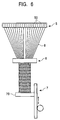
- FIG. 6 is a typical drawing showing the entire construction of a weaving device.
- the weaving device is comprised of a carrier drive section 5, a block drive section 6, a lifting device 7, and other components.
- the carrier drive section 5 has carriers 51 arranged in a matrix form and each having a bobbin 50 loaded thereon.
- the carrier 51 has a cross-shaped slide groove 51a formed in its bottom surface.
- the slide groove 51a is formed to have a generally T-shaped cross section so that a pin 5b fixed to a support plate 5a of the carrier drive section 5 can be fitted therein. This construction enables each carrier 51 to be moved on the support plate 5a in a row and a column direction of the matrix while keeping the bobbin 50 integrally loaded thereon.
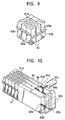
- the block drive section 6 has blocks 61 also arranged in a matrix form and each having a through-hole 61a for a fiber 8.
- the blocks 61, 61, ... are each shaped generally like a rectangular parallelopiped and each have a slide groove 62a formed in a side portion thereof corresponding to the row direction and a projection 62b fitted in the slide groove 62a in the adjacent block.
- the blocks 61, 61, ... each have a slide groove 63a formed in a side portion thereof corresponding to the column direction and a projection 63b fitted in the slide groove 63a in the adjacent block.
- the blocks 61, 61, ... constructed in this manner are arranged in the matrix form so that the blocks 61, 61, ... in the row or column direction can be integrally moved.
- the blocks 61, 61, ... in the row direction have slide plates 64, 65 disposed at an end portion thereof.
- the slide plates 64, 65 are alternately arranged in the column direction, and the plurality of slide plates 64, 64, ... ( Figure 10 shows two slide plates 64, 64) share a drive plate 64a fixedly installed thereon.
- the drive plate 64a has a rack 64b disposed thereon in the row direction and which meshes with a pinion 64d of a pulse motor 64c to convert rotative driving by the pulse motor 64c into reciprocating motion of the slide plates 64, 64, ...
- the plurality of slide plates 65, 65, ... share a drive plate 65a fixedly installed thereon.
- the drive plate 65a has a rack 65b disposed thereon in the row direction and which meshes with a pinion 65d of a pulse motor 65c to convert rotative driving by the pulse motor 65c into reciprocating motion of the slide plates 65, 65, ...
- the slide plates 64, 65 can be slidably moved to correspondingly move the blocks 61, 61, ... of the block drive section 6 every other row (for example, only the even- or odd-number rows).
- the blocks 61, 61, ... in the column direction also have the slide plates, the drive plates, and the pulse motors (not shown in the drawings) disposed thereon to enable the blocks 61, 61, ... to be moved every other column.
- the carriers 51 arranged in the carrier drive section 5 and the blocks 61 arranged in the block drive section 6 are both arranged in a matrix form as shown in Figure 11.
- fibers supplied from the bobbins 50 on the required carriers 51 are allowed to penetrate the through-holes 61a in the corresponding blocks 61 and are then connected to a terminal plate 70 of the lifting device 7.
- the matrix configuration of the block drive section 6 is not necessarily the sane as that of the carrier drive section 5, and the matrix requires only a minimum number of rows and columns required to move the carriers 51 appropriately.
- a method for generating a three-dimensional fibrous tissue in the weaving device constructed as described above will be described below.
- fibers are extended from the bobbins 50 on the required carriers 51, subsequently allowed to penetrate the through-holes 61a in the corresponding blocks 61, and then connected to the terminal plate 70 at corresponding positions.
- the bobbins 50 for supplying fibers can be selected as appropriate depending on the shape of a tissue to be formed, but are continuously arranged in each of the above carrier movement spaces 10 in the row and column directions. That is, the carrier drive section 5 has a plurality of carrier movement spaces 10 disposed therein and extending in the row and column directions.
- the lifting device 7 is used to move the terminal plate 70 in a direction away from the block drive section 6, while the carrier drive section 5 and the block drive section 6 simultaneously perform the above first-layer operation. That is, the block drive section 6 simultaneously performs the first-layer operation in the plurality of carrier movement spaces 10 by using the above slide drive mechanism to move the blocks every other row and column in the row and column directions.
- the carrier drive section 5 carries out slidable movement in synchronism with the slidable movement by the block drive section 6 because the carrier drive section 5 is similarly constructed (not shown in the drawings) to move the blocks every other row and column in the row and column directions.
- the lifting device 7 is used to move the terminal plate 70, while the carrier drive section 5 and the block drive section 6 simultaneously perform the second-layer operation.
- the second-layer woven layer 22g which follows the first-layer woven layer 21g formed by means of the first-layer operation; is formed between the block drive section 6 and the terminal plate 70.
- the above first- and second-layer operations are repeated to sequentially and repeatedly form the first-layer woven layer 21g and the second-layer woven layer 22g between the block drive section 6 and the terminal plate 70. In this manner, a three-dimensional fibrous tissue is formed.
- the fibers are joined together at the nodes 21p by means of adhesion or welding.
- two laser oscillators 9, 9 are used to irradiate the nodes with laser beams.
- the laser oscillators 9, 9 are arranged so as to be moved by feed motors 91, 91 in a row and a column directions of a tissue to be formed and to rotatively move within a plane including the cross section of the tissue.
- the irradiation directions of the two laser oscillators 9, 9 are controlled to join the fibers together at the nodes 21p, 21p, ...
- only target nodes 21p are irradiated with laser beams to avoid the adverse effects of the beams on the other fibers and nodes.
- the output of each of the two laser oscillators 9, 9 can be controlled depending on the distance between this laser oscillator 9, 9 and a node, and output control is carried out based on the total output of the two laser oscillators 9, 9, thereby achieving an efficient joining step without the use of extra energy.
- the output control is configured to correspond to various materials of fibers such as stainless wires, copper wires, nickel wires, nylon yarns, and polyester fibers.
- metallic fibers can be coated with a solder powder, a flux, etc. beforehand.
- Chemical fibers can be deposited using a paste material, and nylon or the like can be deposited using a formic acid.
- an outer frame may be disposed on an outer-most layer of the tissue so as to join by means of adhesion or welding with that part of the outer-most layer which is contained in this outer frame portion, thereby enabling the external shape of the tissue formed to be maintained to omit joining for each node.
- the three-dimensional fibrous tissue formed using the above operations can be used as a filter for various applications.
- the three-dimensional fibrous tissue can be used as a catalyst showing efficient effects when the fibers constituting the three-dimensional fibrous tissue are formed of a member with a catalytic effect.
- the assently angle of the tissue can freely be varied. Consequently, the level of the filtering capability, one of the characteristics of the filter, can be controlled to adjust the intensity of the filter.
- the fiber orientation of the three-dimensional fibrous tissue to be formed can be varied. If the carriers are moved through 90 degrees at a time, this timing with which the operation shifts to the next-layer operation may arbitrarily be selected from 90, 270, and 360 degrees and more.
- the tissue formed may directly be used as a composite or a component without altering its shape. Accordingly, the three-dimensional fibrous tissue can be provided with a plurality of functions or formed into a very light structure or a honeycomb structure.
- the positions and number of the bobbins 50 on the carrier drive section 5 from which the fibers are supplied can arbitrarily be selected within the range of the carrier movement space 10, so that three-dimensional fibrous tissues (or filters) of various shapes or densities can be formed.
- the present method is configured to provide a higher degree of freedom than the conventional methods for weaving a tissue.
- the present invention has the following effects.
- the present invention provides a method for weaving a three-dimensional fibrous tissue by moving carriers arranged in a matrix form, in a row and a column directions of the matrix, wherein weaving is carried out by setting four adjacent partitions in a space within which the carriers are moved and rotating the carriers within this carrier space. Consequently, a weaving base of the three-dimensional fibrous tissue can be formed by means of the simple rotation of the carriers involving a small movement range.
- weaving is carried out by shifting the carrier movement space in the row and column directions of the matrix by one partition to set a next carrier movement space and alternately performing the rotation operation in the first carrier movement space and the next carrier movement space.
- the three-dimensional fibrous tissue can be formed by means of the repetition of the simple independent block operations, thereby facilitating control.
- a filter is woven by a method as in Claim 1 or 2 forming woven layers in a longitudinal direction of fibers at fixed intervals and adhering or welding together yarns crossing one another in the woven layers. As a result, spaces are formed in the woven layers, resulting in a construction providing sufficient filter functions.
- the present invention provides a device for weaving three-dimensional fibrous tissue comprising a carrier drive section for moving carriers arranged in a matrix form, in a row and a column directions of the matrix, the carriers each having a bobbin loaded thereon; a block drive section for similarly moving blocks arranged in a matrix form, in a row and a column direction of the matrix; and a device for lifting a woven three-dimensional fibrous tissue.
- a carrier drive section for moving carriers arranged in a matrix form, in a row and a column directions of the matrix, the carriers each having a bobbin loaded thereon
- a block drive section for similarly moving blocks arranged in a matrix form, in a row and a column direction of the matrix
- a device for lifting a woven three-dimensional fibrous tissue comprising a carrier drive section for moving carriers arranged in a matrix form, in a row and a column directions of the matrix, the carriers each having a bobbin loaded thereon; a block drive section for similarly moving blocks arranged in
Landscapes
- Engineering & Computer Science (AREA)
- Textile Engineering (AREA)
- Manufacturing & Machinery (AREA)
- Looms (AREA)
- Woven Fabrics (AREA)
- Filtering Materials (AREA)
- Braiding, Manufacturing Of Bobbin-Net Or Lace, And Manufacturing Of Nets By Knotting (AREA)
Abstract
Description
Claims (4)
- A method for weaving a three-dimensional fibrous tissue by moving carriers arranged in a matrix form, in a row and a column directions of the matrix, characterized in that weaving is carried out by setting four adjacent partitions in a space within which the carriers are moved and rotating the carriers using this carrier space as a rotation unit.
- A method for weaving a three-dimensional fibrous tissue characterized in that weaving is carried out by shifting said carrier movement space in the row and column directions by one partition to set a next carrier movement space and alternately performing said rotation operation in the first carrier movement space and the next carrier movement space.
- A filter woven by a method as in Claim 1 or 2 characterized in that the filter is obtained by forming woven layers in a longitudinal direction of fibers at fixed intervals and adhering or welding together yarns crossing one another in the woven layers.
- A device for weaving a three-dimensional fibrous tissue comprising a carrier drive section for moving carriers arranged in a matrix form, in a row and a column directions of the matrix, the carriers each having a bobbin loaded thereon; a block drive section for similarly moving blocks arranged in a matrix form, in a row and a column direction of the matrix; and a device for lifting a woven three-dimensional fibrous tissue.
Applications Claiming Priority (2)
| Application Number | Priority Date | Filing Date | Title |
|---|---|---|---|
| JP10623399A JP3482902B2 (en) | 1999-04-14 | 1999-04-14 | Method for weaving three-dimensional fiber tissue, device therefor, and three-dimensional fiber tissue |
| JP10623399 | 1999-04-14 |
Publications (2)
| Publication Number | Publication Date |
|---|---|
| EP1045056A2 true EP1045056A2 (en) | 2000-10-18 |
| EP1045056A3 EP1045056A3 (en) | 2001-09-19 |
Family
ID=14428416
Family Applications (1)
| Application Number | Title | Priority Date | Filing Date |
|---|---|---|---|
| EP00103086A Withdrawn EP1045056A3 (en) | 1999-04-14 | 2000-02-15 | Method and apparatus for weaving three-dimensional fibrous tissue and woven filter |
Country Status (2)
| Country | Link |
|---|---|
| EP (1) | EP1045056A3 (en) |
| JP (1) | JP3482902B2 (en) |
Cited By (2)
| Publication number | Priority date | Publication date | Assignee | Title |
|---|---|---|---|---|
| EP1180557A1 (en) * | 2000-08-09 | 2002-02-20 | Murata Kikai Kabushiki Kaisha | Three dimensional structure, and apparatus and method for manufacturing a three dimensional structure |
| EP1050352A3 (en) * | 1999-04-27 | 2003-11-12 | Tadayoshi Nagaoka | Column packing and method for manufacturing the same |
Families Citing this family (2)
| Publication number | Priority date | Publication date | Assignee | Title |
|---|---|---|---|---|
| JP4568728B2 (en) * | 2003-11-07 | 2010-10-27 | 全南大学校産業財団 | Three-dimensional porous lightweight structure woven directly with continuous wire and manufacturing method thereof |
| JP4548188B2 (en) * | 2005-04-07 | 2010-09-22 | トヨタ紡織株式会社 | Manufacturing method of fiber assembly |
Family Cites Families (5)
| Publication number | Priority date | Publication date | Assignee | Title |
|---|---|---|---|---|
| US4312261A (en) | 1980-05-27 | 1982-01-26 | Florentine Robert A | Apparatus for weaving a three-dimensional article |
| JPH0791744B2 (en) * | 1987-12-29 | 1995-10-04 | 東レ株式会社 | Weaving device for three-dimensional fiber structure |
| US5067525A (en) * | 1988-12-28 | 1991-11-26 | Three-D Composites Research Corporation | Three-dimensional fabric woven by interlacing threads with rotor driven carriers |
| JPH04209850A (en) * | 1990-11-30 | 1992-07-31 | Nippon Oil Co Ltd | Three-dimensional woven fabric of orthogonal tissue and its composite material |
| RU2185469C2 (en) | 1996-10-18 | 2002-07-20 | Е.И. Дюпон Де Немур Энд Компани | Method for rapid manufacture of material |
-
1999
- 1999-04-14 JP JP10623399A patent/JP3482902B2/en not_active Expired - Fee Related
-
2000
- 2000-02-15 EP EP00103086A patent/EP1045056A3/en not_active Withdrawn
Cited By (2)
| Publication number | Priority date | Publication date | Assignee | Title |
|---|---|---|---|---|
| EP1050352A3 (en) * | 1999-04-27 | 2003-11-12 | Tadayoshi Nagaoka | Column packing and method for manufacturing the same |
| EP1180557A1 (en) * | 2000-08-09 | 2002-02-20 | Murata Kikai Kabushiki Kaisha | Three dimensional structure, and apparatus and method for manufacturing a three dimensional structure |
Also Published As
| Publication number | Publication date |
|---|---|
| JP2000303310A (en) | 2000-10-31 |
| JP3482902B2 (en) | 2004-01-06 |
| EP1045056A3 (en) | 2001-09-19 |
Similar Documents
| Publication | Publication Date | Title |
|---|---|---|
| US6448682B2 (en) | Motor laminated core, method of manufacturing same, motor and ink jet recording device | |
| RU2737286C1 (en) | Apparatus and method of controlling an irradiation system for making articles | |
| DE60311045T2 (en) | Segmented armature and AC machine using same | |
| US6186185B1 (en) | Network-like woven 3D fabric material | |
| DE2643918B2 (en) | ||
| DE3851610T2 (en) | Reader with light scanning. | |
| KR20000075913A (en) | Woven 3d fabric material | |
| DE102005039465A1 (en) | Micromachined ultrasonic transducer device for medical diagnostic ultrasound imaging system, has unit switch cells, each includes switches for closing pathways to connection point that is connected to respective sensor | |
| US4241117A (en) | Structural cores and their fabrication | |
| DE69702021T2 (en) | Diode array for diode-pumped solid-state lasers | |
| DE2628492B1 (en) | DEVICE FOR EXAMINATION OF BODIES BY SCANING USING ULTRASOUND | |
| US3998173A (en) | Stitched wire electrical structure and method of making same | |
| DE4004682C2 (en) | Magnetic blanket | |
| RU2174438C1 (en) | Packing for columns and method of its manufacture | |
| CN103688602B (en) | Manufacture of substrates and apparatus for manufacturing substrate | |
| JP3482902B2 (en) | Method for weaving three-dimensional fiber tissue, device therefor, and three-dimensional fiber tissue | |
| JP2535117B2 (en) | Device for knitting three-dimensional braid structure | |
| KR100767186B1 (en) | Light weight sandwich plate with intermediate layer consisting of wires and method of manufacturing the same | |
| CN110923942B (en) | Edge-sealing knotless net weaving equipment and method | |
| US10434564B2 (en) | Method for manufacturing three-dimensional lattice truss structure using flexible linear bodies | |
| JPH0596101A (en) | Production of packing or the like in device for mass transfer or the like | |
| CN217252830U (en) | Three-dimensional structure electronic device and manufacturing apparatus | |
| EP4239814A1 (en) | High peak power laser diode assembly | |
| JPH0233121B2 (en) | ||
| KR20110098399A (en) | 3D truss structure loom and 3D truss structure manufacturing method using the same |
Legal Events
| Date | Code | Title | Description |
|---|---|---|---|
| PUAI | Public reference made under article 153(3) epc to a published international application that has entered the european phase |
Free format text: ORIGINAL CODE: 0009012 |
|
| AK | Designated contracting states |
Kind code of ref document: A2 Designated state(s): CH DE LI Kind code of ref document: A2 Designated state(s): AT BE CH CY DE DK ES FI FR GB GR IE IT LI LU MC NL PT SE |
|
| AX | Request for extension of the european patent |
Free format text: AL;LT;LV;MK;RO;SI |
|
| PUAL | Search report despatched |
Free format text: ORIGINAL CODE: 0009013 |
|
| AK | Designated contracting states |
Kind code of ref document: A3 Designated state(s): AT BE CH CY DE DK ES FI FR GB GR IE IT LI LU MC NL PT SE |
|
| AX | Request for extension of the european patent |
Free format text: AL;LT;LV;MK;RO;SI |
|
| 17P | Request for examination filed |
Effective date: 20011018 |
|
| AKX | Designation fees paid |
Free format text: CH DE LI |
|
| STAA | Information on the status of an ep patent application or granted ep patent |
Free format text: STATUS: THE APPLICATION HAS BEEN WITHDRAWN |
|
| 18W | Application withdrawn |
Effective date: 20030114 |