EP1044872A2 - Derailleur for a bicycle - Google Patents
Derailleur for a bicycle Download PDFInfo
- Publication number
- EP1044872A2 EP1044872A2 EP00107417A EP00107417A EP1044872A2 EP 1044872 A2 EP1044872 A2 EP 1044872A2 EP 00107417 A EP00107417 A EP 00107417A EP 00107417 A EP00107417 A EP 00107417A EP 1044872 A2 EP1044872 A2 EP 1044872A2
- Authority
- EP
- European Patent Office
- Prior art keywords
- derailleur
- guiding member
- fixed member
- chain guiding
- pivot pins
- Prior art date
- Legal status (The legal status is an assumption and is not a legal conclusion. Google has not performed a legal analysis and makes no representation as to the accuracy of the status listed.)
- Granted
Links
- 230000008878 coupling Effects 0.000 claims description 3
- 238000010168 coupling process Methods 0.000 claims description 3
- 238000005859 coupling reaction Methods 0.000 claims description 3
- 230000007246 mechanism Effects 0.000 description 8
- 238000003780 insertion Methods 0.000 description 3
- 230000037431 insertion Effects 0.000 description 3
- 230000000712 assembly Effects 0.000 description 2
- 238000000429 assembly Methods 0.000 description 2
- 239000003562 lightweight material Substances 0.000 description 2
- 239000000463 material Substances 0.000 description 2
- 230000005540 biological transmission Effects 0.000 description 1
- 238000004140 cleaning Methods 0.000 description 1
- 230000002860 competitive effect Effects 0.000 description 1
- 238000012986 modification Methods 0.000 description 1
- 230000004048 modification Effects 0.000 description 1
- 230000004044 response Effects 0.000 description 1
Images



Classifications
-
- B—PERFORMING OPERATIONS; TRANSPORTING
- B62—LAND VEHICLES FOR TRAVELLING OTHERWISE THAN ON RAILS
- B62M—RIDER PROPULSION OF WHEELED VEHICLES OR SLEDGES; POWERED PROPULSION OF SLEDGES OR SINGLE-TRACK CYCLES; TRANSMISSIONS SPECIALLY ADAPTED FOR SUCH VEHICLES
- B62M9/00—Transmissions characterised by use of an endless chain, belt, or the like
- B62M9/04—Transmissions characterised by use of an endless chain, belt, or the like of changeable ratio
- B62M9/06—Transmissions characterised by use of an endless chain, belt, or the like of changeable ratio using a single chain, belt, or the like
- B62M9/10—Transmissions characterised by use of an endless chain, belt, or the like of changeable ratio using a single chain, belt, or the like involving different-sized wheels, e.g. rear sprocket chain wheels selectively engaged by the chain, belt, or the like
- B62M9/12—Transmissions characterised by use of an endless chain, belt, or the like of changeable ratio using a single chain, belt, or the like involving different-sized wheels, e.g. rear sprocket chain wheels selectively engaged by the chain, belt, or the like the chain, belt, or the like being laterally shiftable, e.g. using a rear derailleur
- B62M9/121—Rear derailleurs
- B62M9/126—Chain guides; Mounting thereof
-
- B—PERFORMING OPERATIONS; TRANSPORTING
- B62—LAND VEHICLES FOR TRAVELLING OTHERWISE THAN ON RAILS
- B62M—RIDER PROPULSION OF WHEELED VEHICLES OR SLEDGES; POWERED PROPULSION OF SLEDGES OR SINGLE-TRACK CYCLES; TRANSMISSIONS SPECIALLY ADAPTED FOR SUCH VEHICLES
- B62M9/00—Transmissions characterised by use of an endless chain, belt, or the like
- B62M9/04—Transmissions characterised by use of an endless chain, belt, or the like of changeable ratio
- B62M9/06—Transmissions characterised by use of an endless chain, belt, or the like of changeable ratio using a single chain, belt, or the like
- B62M9/10—Transmissions characterised by use of an endless chain, belt, or the like of changeable ratio using a single chain, belt, or the like involving different-sized wheels, e.g. rear sprocket chain wheels selectively engaged by the chain, belt, or the like
- B62M9/12—Transmissions characterised by use of an endless chain, belt, or the like of changeable ratio using a single chain, belt, or the like involving different-sized wheels, e.g. rear sprocket chain wheels selectively engaged by the chain, belt, or the like the chain, belt, or the like being laterally shiftable, e.g. using a rear derailleur
- B62M9/121—Rear derailleurs
- B62M9/124—Mechanisms for shifting laterally
- B62M9/1242—Mechanisms for shifting laterally characterised by the linkage mechanisms
Definitions
- This invention generally relates to a derailleur for a bicycle. More specifically, the present invention relates to a derailleur for a bicycle that can be easily disassembled for replacing the parallel links.
- Bicycling is becoming an increasingly more popular form of recreation as well as a means of transportation. Moreover, bicycling has become a very popular competitive sport for both amateurs and professionals. Whether the bicycle is used for recreation, transportation or competition, the bicycle industry is constantly improving the various components of the bicycle. One part of the bicycle that has been extensively redesigned is the drive train of the bicycle.
- Most of today's bicycles are multi-speed bicycles that allow the rider to select the appropriate gear ratio to suit the particular riding conditions encountered during the bicycle ride.
- One of the most popular types of gearing assemblies for multi-speed bicycles utilize a chain extending between a set of front sprockets mounted for rotation with the pedals and a set of rear sprockets mounted on the rear hub of the rear bicycle wheel for rotation therewith.
- a front derailleur is used to move the chain between the front sprockets or gears.
- most derailleur front or rear derailleurs
- most derailleurs front or rear derailleurs
- most derailleurs include a fixed member nonmovably secured to a bicycle frame, and a movable chain guiding member supported for movement relative to the fixed member.
- the chain ding member has a pair of guide plates that forms a chain receiving slot for contacting and moving a chain between the sprockets.
- sprockets are rotatably mounted between the guide plates.
- the front derailleur is designed to hold the chain on the inner sprocket, i.e., the sprocket closest to the center of the bicycle.
- the rear derailleur is normally arranged to position the chain on the outermost sprocket in its rest position.
- the operating conduit or cable pulls the front derailleur such that the chain is moved outwardly from one gear or sprocket to the next gear or sprocket, or releases the front derailleur such that the chain is moved inwardly from one gear or sprocket to the next gear or sprocket.
- the operating conduit or cable pulls the rear derailleur such that it moves the chain inwardly from one gear or sprocket to the next inner gear or sprocket, or releases the rear derailleur such that it moves the chain outwardly from one gear or sprocket to the next gear or sprocket.
- the shift operating devices are moved to release the derailleur, the front derailleur will move inwardly towards the center of the bicycle, while the rear derailleur will move outwardly away from the center of the bicycle.
- the front and rear derailleurs are constantly being redesigned to operate more efficiently and to improve the design such that they can be made lighter. Accordingly, deraille are typically constructed of lightweight materials and are made as thin as possible. Of course, this can result in the parts wearing out at a faster rate. Therefore, it is desirable to reduce wear in the more expensive parts of the derailleur or the more difficult parts to remove. Moreover, it is desirable to design the derailleur such that parts can be easily removed for cleaning and/or replacement.
- One object of the present invention is to provide a derailleur for a bicycle that can be easily assembled and/or disassembled for replacing the parallel links.
- Another object of the present invention is to provide a derailleur for a bicycle that reduces the amount of wear occurring on either the fixed member or the chain guiding (movable) member.
- a rear derailleur for a bicycle comprising a fixed member, a chain guiding member arid a linkage assembly.
- the fixed member is adapted to be coupled to a portion of the bicycle.
- the chain guiding member shifts a chain of the bicycle in a transverse direction.
- the linkage assembly is coupled between the fixed member and the chain guiding member to move the chain guide between a retracted position and an extended position.
- the linkage assembly includes pivot pins coupling the fixed member and the chain guiding member thereto. At least one of the pivot pins is removably and non-rotatably coupled to one of the fixed member or the chain guiding member.
- a bicycle 10 is illustrated with derailleurs 12 and 14 in accordance with the present invention installed thereon as discussed below.
- Bicycle 10 and its various components are well known in the prior art, except that derailleurs 12 and 14 have been modified as explained below.
- deraille 12 and 14 have been modified as explained below.
- bicycle 10 and its various components will not be discussed or illustrated in detail herein, except for the components that relate to the present invention.
- bicycle 10 has a frame 16 with a front fork 18 movably coupled thereto, a rear wheel 20 rotatably coupled to frame 16, a front wheel 22 rotatably coupled to frame 16, a seat 24 adjustably coupled to frame 16, a handlebar 26 coupled to front fork 18 for turning front wheel 22 and a drive train 30 for propelling bicycle 10.
- Drive train 30 basically includes derailleurs 12 and 14, a front crank set 32 rotatably coupled to frame 16 via a bottom bracket (not shown), a pair of crank arms 34 with pedals 36, a drive chain 38 and a freewheel assembly 40 coupled to rear wheel 20 in a conventional manner.
- rear derailleur 12 in accordance with the present invention is illustrated as being coupled to frame 16 of a bicycle 10 (only a portion illustrated in Figure 2).
- Rear derailleur 12 is a pneumatically operated derailleur, such as the one disclosed in U.S. Patent Application Serial No. 08/846,265 for gas actuated transmission for a bicycle which was filed with the U.S. Patent and Trademark Office on April 29, 1997.
- the disclosure of Patent Application Serial No. 08/846,265 is incorporated herein by reference to fully explain the operation and structure of rear derailleur 12.
- rear derailleur 12 is illustrated as being coupled to the rear fork end of frame 16 of a bicycle 10 for cooperating with freewheel assembly 40 in a conventional manner. While freewheel assembly 40 is illustrated with seven rear gears G1-G7, it will become apparent to those skilled in the art from this disclosure that freewheel assembly 40 can have fewer or more gears as needed and/or desired Chain 38 is operatively coupled to rear gears G1-G7 and to front gears of crank set 32 in a conventional manner for transmitting the desired rotational torque to the rear wheel 20 of the bicycle 10.
- Rear derailleur 12 is coupled to a rear shifting unit 42 ( Figure 1) via a pair of air tubes or conduits 44 in a conventional manner.
- Conduits 44 provide a shifting force to rear derailleur 12 for moving chain 38 between gears G1-G7.
- air from the conduits 44 either pulls rear derailleur 12 to move chain 38 inwardly to engage the next gear or releases rear derailleur 12 to move chain 38 outwardly to engage the next gear.
- chain 38 is either moved inwardly towards the center plane of bicycle 10 to engage the next larger gear or sprocket, or moved outwardly away from the center plane of bicycle 10 to engage the next smaller gear or sprocket
- Rear derailleur 12 is designed to be normally biased outwardly such that chain 38 is normally positioned on the outermost gear G1.
- rear derailleur 12 is disclosed as being pneumatically operated by shifting unit 42, it will be apparent to those skilled in the art from this disclosure that the present invention can be applied to other types of derailleur such as a cable operated derailleur. Since the basic structure and operation of rear derailleur 12 are well known in the art, only the parts of rear derailleur 12 that relate to the present invention will be discussed and illustrated herein. Moreover, shifting unit 42 can be practically any type of shifting unit. Therefore, the precise structure of shifting unit 42 will not be discussed or illustrated in detail herein.
- rear derailleur 12 basically includes a fixed member 50 with a bracket axle assembly 52, a chain guiding member 54, a linkage assembly 56, and a biasing member 59.
- Chain guiding member 54 is movably coupled to fixed member 50 via a linkage assembly 56.
- Biasing member 59 is preferably in the form of a coil tension spring that urges chain guiding member 54 outwardly from the center plane of the bicycle 10.
- bracket axle assembly 52 Fixed member 50 is fixedly coupled to frame 16 of the bicycle 10 by bracket axle assembly 52 in a conventional manner. Since bracket axle assemblies are well known in the bicycle art, the structure of bracket axle assembly 52 will not be discussed or illustrated in detail herein. While bracket axle assembly 52 is illustrated as being coupled directly to frame 16, it will be apparent to those skilled in the art from this disclosure that a removable derailleur hanger or hanging plate (not shown) can be utilized to connect bracket axle assembly 52 of rear derailleur 12 to frame 16. These types of derailleur hangers (not shown) are well known in the art, and thus, will not be discussed or illustrated hereon.
- Two pneumatic air tubes 44 are coupled to fixed member 50 in a conventional manner. Air tubes 44 apply a shifting force on linkage assembly 56 for shifting or moving chain guiding member 54 relative to fixed member.
- linkage assembly 56 holds chain guiding member 54 in its extended position
- chain guiding member 54 is located over the outermost sprocket G1, i.e., the furthest sprocket from the center plane of bicycle 10.
- Shifting unit 42 controls these movements of chain guiding member 54 and linkage assemble 56 by selectively applying air to rear derailleur 12. Specifically, when the rider operates shifting unit 42, air pressure moves linkage assembly 56 to pull or release chain guiding member 54 between its extended position and its retracted position.
- fixed member 50 is coupled to linkage assembly 56 via a pair of pivot pins 58.
- Pivot pins 58 are designed so that they do not rotate relative to fixed member 50. Since pivot pins 58 do not rotate relative to fixed member 50, the amount of wear in fixed member 50 is minimized.
- fixed member 50 has a pair of vertically spaced flanges 60 that are parallel to each other. As seen in Figure 5, each of these flanges 60 has a pair of holes 62 that are axially aligned with the holes 62 of the other flange 60. Each pair of axially aligned holes 62 receives one of the pivot pins 58 in a non-rotatably manner as discussed below.
- the upper one of the flanges 60 has a pair of abutment surfaces 64 that engages pivot pins 58 to prevent relative movement.
- these abutment surfaces 64 are located adjacent the holes 62 in the upper flange 60 to engage the pivot pins 58 to prevent rotational movement of the pivot pins 58 relative to fixed member 50.
- abutment surfaces 64 are flat surfaces or walls that extend upwardly from fixed member 50 in directions that are parallel to the longitudinal axes of holes 62.
- other shapes of abutment surfaces can be utilized to carry out the present invention.
- Pivot pins 58 each have a head portion 65 with a shaft portion 66 extending therefrom.
- Head portion 65 has a circumferential side surface with an abutment surface 68 formed thereon.
- the abutment surface 68 of each head portion 65 is a flat surface that has a complimentary shape corresponding to the shape of abutment surface 64 of the fixed member 50.
- each head portion 65 is also provided with a slot 70 for receiving a tool such as a screwdriver for aiding in the assembly and disassembly of rear derailleur 12.
- the free ends 72 of shaft portions 66 are preferably conically tapered to form a substantially pointed tip.
- the tapered free ends 72 of pivot pins 58 aid in the insertion of pivot pins 58 into holes 62 and the corresponding holes of linkage assembly 56.
- the shaft portion 66 of each pivot pin 58 is also provided with an annular groove 74 that is located adjacent to its free end 72. Grooves 74 are adapted to receive E-clips or other similar types of retaining clips 78. Accordingly, pivot pins 58 can be easily installed and easily removed for attaching or detaching linkage assembly 56 and chain guiding member 54 from fixed member 50. In other words, the linkage assembly 56 and chain guiding member 54 can be easily removed and replaced when they become worn out.
- chain guiding member 54 basically includes a movable member 80, a pair of guide plates 82 and a pair of sprockets 84 (only one shown). Movable member 80 is pivotally coupled to linkage assembly 56 via pivot pins 86. Guide plates 82 are rotatably coupled to movable member 80 in a conventional manner such that chain 38 is placed under tension by sprockets 84. Chain guiding member 54 has a chain receiving slot formed by guide plates 82 that are adapted to engage chain 38 for moving chain 38 in a direction transverse to bicycle 10. Sprockets 84 are rotatably coupled between guide plates 80 for engaging chain 38 in a conventional manner. Since chain guiding member 54 is relatively conventional, the additional parts of chain guiding member 54 will not be discussed or illustrated in detail herein.
- linkage assembly 56 basically includes an inner link 88 and outer link 89.
- Links 88 and 89 are provided with pivot holes (not shown) at each end for receiving pivot pins 58 and 86. More specifically, links 88 and 89 are pivotally coupled at one end to fixed member 50 by pivot pins 58. The other ends of links 88 and 89 are pivotally coupled to chain guiding members 54 by pivot pins 86.
- the biasing member 59 is coupled between the fixed member 50 by pin 91 (Fig. 2) and the inner link 88 of the linkage assembly 56 by pin 92. Spring 59 normally biases chain guiding member 54 outwardly away from the center of bicycle 10.
- each of these components of linkage assembly 56 are constructed of relatively lightweight, rigid materials which are known in the art.
- Biasing member 59 is preferably a coiled tension spring having a first end mounted on pivot pin 91 of fixed member 50 and a second end mounted on pin 92 of inner link 88 for normally biasing chain guiding member 54 from its extended position to its retracted position.
- biasing member or coil spring 59 expands and contracts in an axial direction, and is normally placed under tension to urge the cable guiding member 54 from its extended position to its retracted position.
- shifting unit 42 which in turn activates a pneumatic shifting mechanism to supply pressurized air to rear derailleur 12 in a relatively conventional manner.
- Outer link 89 has a pair of threaded holes for receiving adjustment screws 95 and 96 thereto.
- Adjustment screw 95 is a low gear position adjustment screw
- adjustment screw 96 is a high gear position adjustment screw.
- Adjustment screw 95 engages a portion of fixed member 50
- adjustment screw 96 engages a portion of chain guiding member 54 for controlling the range of movement of chain guiding member 54.
- the axial extension of adjustment screws 95 and 96 the extended (low or larger gear) position and the retracted (high or smaller gear) position of chain guiding member 54 are adjusted independently of each other.
- fixed member 50 is provided with a low gear stopping surface 97
- chain guiding member 54 is provided with a high gear stopping surface 98 as best seen in Figure 3.
- Low gear stopping surface 97 is designed to engage the free end of adjustment screw 95
- high gear stopping surface 98 is positioned to engage the free end of adjustment screw 96. Since this is a relatively conventional adjustment mechanism that is well known in the prior art, this adjustment mechanism will not be discussed or illustrated in detail herein.
- An intermediate member 99 is coupled to fixed member 50 and includes an indexing mechanism contained therein for moving chain guiding member 54 in response to operation shifting unit 42.
- An example for an indexing mechanism which is contained within intermediate member 99 is disclosed in U.S. Patent Application Serial No. 08/846,265. Accordingly, when the rider operates the pneumatic shifting unit 42, the intermediate member 99 will cause linkage assembly 56 to pivot inwardly against the biasing force of spring 59, which in turn moves the chain guiding member 54 attached thereto inwardly towards the center of the bicycle. This movement of chain guiding member 54 will also cause the chain 38 to move from an outer (smaller) gear to the next inner (larger) gear. Of course, if the shift operating mechanism is moved to allow the linkage assembly 56 to move under the biasing force of spring 59, the linkage assembly 56 will move chain guiding member 54 and chain 38 outwardly from a larger gear to the next smaller gear.
- FIG. 6 a rear derailleur 112 is illustrated in accordance with another embodiment of the present invention.
- This embodiment is substantially identical to the first embodiment, except that the fixed member 150 and the chain guiding member 154 have been slightly modified.
- this embodiment will not be discussed or illustrated in as much detail as the first embodiment.
- the descriptions of the parts of the first embodiment applies to similar parts of this second embodiment.
- rear derailleur 112 basically includes a fixed member 150 with a bracket axle assembly 152, a chain guiding member 154, a linkage assembly 156, and a biasing member 159.
- Chain guiding member 154 is movably coupled to fixed member 150 via a linkage assembly 156.
- Biasing member 159 is preferably in the form of a coil tension spring that urges chain guiding member 154 outwardly from the center plane of the bicycle 10.
- Fixed member 150 is coupled to linkage assembly 156 via a pair of pivot pins 158.
- chain guiding member 154 is also coupled to linkage assembly 156 via a pair of smaller pivot pins 158'.
- Pivot pins 158' are substantially identical to pivot pins 158, except that they are smaller in size. Pivot pins 158 are designed so that they will not rotate relative to fixed member 150, while pivot pins 158' are designed so that they will not rotate relative to chain guiding member 154. Since pivot pins 158 and 158' do not rotate relative to fixed member 150 or chain guiding member 154, respectively, the amount of wear in members 150 and 154 is minimized.
- the upper flange 160 of fixed member 150 is provided with a pair of recesses 161 that are coaxially formed about the holes 162. These recesses 161 are sized to receive the head portion 165 of the pivot pin 158. More specifically, these recesses 161 form abutment surfaces 164 that engage pivot pins 158 to prevent relative movement.
- abutment surfaces 164 are flat surfaces or walls that extend upwardly from fixed member 150 in directions that are parallel to the longitudinal axes of holes 162.
- other shapes of the abutment surfaces or recesses can be utilized to carry out the present invention.
- Pivot pins 158 each have a head portion 165 with a shaft portion 166 extending therefrom.
- Head portion 165 has a circumferential side surface with an abutment surface 168 formed thereon.
- the abutment surface 168 of each head portion 165 is a flat surface that has a complimentary shape corresponding to the shape of the abutment surface 164 of fixed member 150.
- each shaft potion 166 is preferably conically tapered to form a substantially pointed tip or a truncated cone.
- the tapered free ends 172 of pins 158 aid in the insertion of pins 158 into holes 162 and the corresponding holes of linkage assembly 156.
- the shaft portion 166 of each pivot pin 158 is also provided with an annular groove 174 that is located adjacent its free end 172. Grooves 174 receive E-clips or other similar types of retaining clips 178.
- pivot pins 158 can be easily installed and/or easily removed for attaching or detaching linkage assembly 156 and chain guiding member 154 from fixed member 150.
- the upper flange 160' of chain guiding member 154 is provided with a pair of recesses 161' that are coaxially formed about the holes 162'.
- These recesses 161' are sized to receive the head portion 165' of the pivot pin 158'. More specifically, these recesses 161' form abutment surfaces 164' that engage pivot pins 158, to prevent relative movement.
- abutment surfaces 164' are flat surfaces or walls tat extend upwardly from chain guiding member 154 in directions that are parallel tote longitudinal axes of holes 162'.
- other shapes of the abutment surfaces or recesses can be utilized to carry out the present invention.
- Pivot pins 158' each have ahead potion 165' with a shaft potion 166' extending therefrom.
- Head portion 165' has a circumferential side surface with an abutment surface 168' formed thereon.
- the abutment surface 168 'of each head portion 165' is a flat surface that has a complimentary shape corresponding to the shape of the abutment surface 164' of chain guiding member 154.
- each shaft portion 166' is preferably conically tapered to form a substantially pointed tip or a truncated cone.
- the tapered free ends 172' of pins 158' aid in the insertion of pins 158' into holes 162' and the corresponding holes of linkage assembly 156.
- the shaft portion 166' of each pivot pin 158 is also provided with an annular groove 174' that is located adjacent its free end 172'. Grooves 174' receive E-clips or other similar types of retaining clips 178'.
- pivot pins 158' can be easily installed and/or easily removed for attaching or detaching chain guiding member 154 from linkage assembly 156.
- a rear derailleur 212 is illustrated in accordance with another embodiment of the present invention.
- This embodiment is substantially identical to the first embodiment, except that a retaining plate 278 has been added to the fixed member 250 for retaining pivot pins 258 thereto. Accordingly, retaining clips 78 of the first embodiment have been eliminated as well as the grooves 74 of pins 58 of the first embodiment.
- this embodiment will not be discussed or illustrated in as much detail as the first embodiment.
- the descriptions of the parts of the first embodiment applies to similar parts of this third embodiment.
- rear derailleur 212 basically includes a fixed member 250 with a bracket axle assembly 252, a chain guiding member 254, a linkage assembly 256, and a biasing member 259.
- Chain guiding member 254 is movably coupled to fixed member 250 via a linkage assembly 256.
- Biasing member 259 is preferably in the form of a coil tension spring that urges chain guiding member 254 outwardly from the center plane of the bicycle 10.
- Fixed member 250 is coupled to linkage assembly 256 via a pair of pivot pins 258.
- chain guiding member 254 is also coupled to linkage assembly 258 via a pair of pivot pins 286. Since pivot pins 258 do not rotate relative to fixed member 250, the amount of wear in fixed members 250 is minimized.
- the upper flange 260 of fixed member 250 has a pair of abutment surfaces 264 that engages pivot pins 258 to prevent relative movement. In other words, these abutment surfaces 264 are located adjacent the holes 262 in the upper flange 260 to engage the pivot pins 258 to prevent rotational movement of the pivot pins 258 relative to fixed member 250.
- abutment surfaces 264 are flat surfaces or walls that extend upwardly from fixed member 250 in directions that are parallel to the longitudinal axes of holes 262.
- abutment surfaces 264 are flat surfaces or walls that extend upwardly from fixed member 250 in directions that are parallel to the longitudinal axes of holes 262.
- Pivot pins 258 each have a head portion 265 with a shaft potion 266 extending therefrom.
- Head potion 265 has a circumferential side surface with an abutment surface 268 formed thereon.
- the abutment surface 268 of each head portion 265 is a flat surface that has a complimentary shape corresponding to the shape of the abutment surface 264 of fixed member 250.
- Retaining plate 278 is removably coupled to fixed member 250 via a bolt 279.
- retaining plate 278 is constructed of a rigid, lightweight material such as a hard plastic material.
- the retaining plate 278 is a U-shaped member with end portions that engage the upper surface of head potions 265 of pivot pins 258 to retain pivot pins 258 within holes 262 of fixed member 250 as seen in Figure 9.
Landscapes
- Engineering & Computer Science (AREA)
- Chemical & Material Sciences (AREA)
- Combustion & Propulsion (AREA)
- Transportation (AREA)
- Mechanical Engineering (AREA)
- Devices For Conveying Motion By Means Of Endless Flexible Members (AREA)
- Transmissions By Endless Flexible Members (AREA)
- Handcart (AREA)
- Gear-Shifting Mechanisms (AREA)
Abstract
Description
- This invention generally relates to a derailleur for a bicycle. More specifically, the present invention relates to a derailleur for a bicycle that can be easily disassembled for replacing the parallel links.
- Bicycling is becoming an increasingly more popular form of recreation as well as a means of transportation. Moreover, bicycling has become a very popular competitive sport for both amateurs and professionals. Whether the bicycle is used for recreation, transportation or competition, the bicycle industry is constantly improving the various components of the bicycle. One part of the bicycle that has been extensively redesigned is the drive train of the bicycle.
- Most of today's bicycles are multi-speed bicycles that allow the rider to select the appropriate gear ratio to suit the particular riding conditions encountered during the bicycle ride. One of the most popular types of gearing assemblies for multi-speed bicycles utilize a chain extending between a set of front sprockets mounted for rotation with the pedals and a set of rear sprockets mounted on the rear hub of the rear bicycle wheel for rotation therewith. A front derailleur is used to move the chain between the front sprockets or gears. Generally, most derailleurs (front or rear derailleurs) include a fixed member nonmovably secured to a bicycle frame, and a movable chain guiding member supported for movement relative to the fixed member. The chain ding member has a pair of guide plates that forms a chain receiving slot for contacting and moving a chain between the sprockets. In the case of a rear derailleur, sprockets are rotatably mounted between the guide plates.
- Normally, the front derailleur is designed to hold the chain on the inner sprocket, i.e., the sprocket closest to the center of the bicycle. The rear derailleur, on the other hand, is normally arranged to position the chain on the outermost sprocket in its rest position. In other words, when the rider operates the shift operating device of the front derailleur shifting mechanism, the operating conduit or cable pulls the front derailleur such that the chain is moved outwardly from one gear or sprocket to the next gear or sprocket, or releases the front derailleur such that the chain is moved inwardly from one gear or sprocket to the next gear or sprocket. When the rider operates the shift operating device of the rear derailleur shifting mechanism, the operating conduit or cable pulls the rear derailleur such that it moves the chain inwardly from one gear or sprocket to the next inner gear or sprocket, or releases the rear derailleur such that it moves the chain outwardly from one gear or sprocket to the next gear or sprocket. In other words, when the shift operating devices are moved to release the derailleur, the front derailleur will move inwardly towards the center of the bicycle, while the rear derailleur will move outwardly away from the center of the bicycle.
- The front and rear derailleurs are constantly being redesigned to operate more efficiently and to improve the design such that they can be made lighter. Accordingly, derailleurs are typically constructed of lightweight materials and are made as thin as possible. Of course, this can result in the parts wearing out at a faster rate. Therefore, it is desirable to reduce wear in the more expensive parts of the derailleur or the more difficult parts to remove. Moreover, it is desirable to design the derailleur such that parts can be easily removed for cleaning and/or replacement.
- In view of the above, there exists a need for a derailleur for a bicycle which overcomes the above mentioned problems in the prior art. This invention addresses this need in the prior art as well as other needs, which will become apparent to those skilled in the art from this disclosure.
- One object of the present invention is to provide a derailleur for a bicycle that can be easily assembled and/or disassembled for replacing the parallel links.
- Another object of the present invention is to provide a derailleur for a bicycle that reduces the amount of wear occurring on either the fixed member or the chain guiding (movable) member.
- The foregoing objects can basically be attained by providing a rear derailleur for a bicycle comprising a fixed member, a chain guiding member arid a linkage assembly. The fixed member is adapted to be coupled to a portion of the bicycle. The chain guiding member shifts a chain of the bicycle in a transverse direction. The linkage assembly is coupled between the fixed member and the chain guiding member to move the chain guide between a retracted position and an extended position. The linkage assembly includes pivot pins coupling the fixed member and the chain guiding member thereto. At least one of the pivot pins is removably and non-rotatably coupled to one of the fixed member or the chain guiding member.
- These and other objects, features, aspects and advantages of the present invention will become apparent to those skilled in the art from the following detailed description, which, taken in conjunction with the annexed drawings, discloses preferred embodiments of the present invention.
- Referring now to the attached drawings which form a part of this original disclosure:
- Figure 1 is a side elevational view of a conventional bicycle with a rear derailleur coupled thereto in accordance with one embodiment of the present invention;
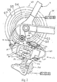
- Figure 2 is a partial side elevational view of the bicycle illustrated in Figure 1 with the rear derailleur in accordance with the present invention mounted on the frame of the bicycle;
- Figure 3 is a partial perspective view of the rear derailleur illustrated in Figure 2 in accordance with the present invention with certain portions broken away for the purposes of illustration;
- Figure 4 is a bottom plan view of the rear derailleur illustrated in Figures 2 and 3 in accordance with the present invention;
- Figure 5 is a partially exploded perspective view of a portion of the rear derailleur illustrated in Figures 2-4 in accordance with the present invention with certain portions broken away for the purposes of illustration;
- Figure 6 is a partially exploded perspective view of a modified rear derailleur in accordance with an alternate embodiment of the present invention;
- Figure 7 is a partial perspective view of the rear derailleur illustrated in Figure 6 with certain portions broken away for the purposes of illustration;
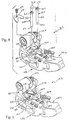
- Figure 8 is a partially exploded perspective view of a modified rear derailleur in accordance with an alternate embodiment of the present invention; and
- Figure 9 is a partial perspective view of the rear derailleur illustrated in Figure 8 with certain portions broken away for the purposes of illustration.
-
- Referring initially to Figure 1, a
bicycle 10 is illustrated withderailleurs 12 and 14 in accordance with the present invention installed thereon as discussed below.Bicycle 10 and its various components are well known in the prior art, except thatderailleurs 12 and 14 have been modified as explained below. Thus,bicycle 10 and its various components will not be discussed or illustrated in detail herein, except for the components that relate to the present invention. - As used herein, the following directional terms "forward, rearward, upward, above, downward, vertical, horizontal, below and transverse" as well as any other similar directional terms refer to those directions of a bicycle in its normal riding position, which
derailleurs 12 and 14 are attached. Accordingly, these terms, as utilized to describe thederailleurs 12 and 14 in the claims, should be interpreted relative tobicycle 10 in its normal riding position. - Basically,
bicycle 10 has aframe 16 with afront fork 18 movably coupled thereto, a rear wheel 20 rotatably coupled toframe 16, afront wheel 22 rotatably coupled toframe 16, aseat 24 adjustably coupled toframe 16, a handlebar 26 coupled tofront fork 18 for turningfront wheel 22 and adrive train 30 for propellingbicycle 10.Drive train 30 basically includesderailleurs 12 and 14, a front crank set 32 rotatably coupled toframe 16 via a bottom bracket (not shown), a pair ofcrank arms 34 withpedals 36, adrive chain 38 and afreewheel assembly 40 coupled to rear wheel 20 in a conventional manner. Since these parts ofbicycle 10 are well known in the art, these parts will not be discussed or illustrated in detail herein, except as they are modified in accordance with the present invention.
Referring now to Figure 2,rear derailleur 12 in accordance with the present invention is illustrated as being coupled toframe 16 of a bicycle 10 (only a portion illustrated in Figure 2). Rearderailleur 12, as illustrated in the drawings, is a pneumatically operated derailleur, such as the one disclosed in U.S. Patent Application Serial No. 08/846,265 for gas actuated transmission for a bicycle which was filed with the U.S. Patent and Trademark Office on April 29, 1997. The disclosure of Patent Application Serial No. 08/846,265 is incorporated herein by reference to fully explain the operation and structure ofrear derailleur 12. - More specifically,
rear derailleur 12 is illustrated as being coupled to the rear fork end offrame 16 of abicycle 10 for cooperating withfreewheel assembly 40 in a conventional manner. Whilefreewheel assembly 40 is illustrated with seven rear gears G1-G7, it will become apparent to those skilled in the art from this disclosure thatfreewheel assembly 40 can have fewer or more gears as needed and/or desiredChain 38 is operatively coupled to rear gears G1-G7 and to front gears of crank set 32 in a conventional manner for transmitting the desired rotational torque to the rear wheel 20 of thebicycle 10. -
Rear derailleur 12 is coupled to a rear shifting unit 42 (Figure 1) via a pair of air tubes orconduits 44 in a conventional manner.Conduits 44 provide a shifting force torear derailleur 12 for movingchain 38 between gears G1-G7. When the rider moves theshift unit 42, air from theconduits 44 either pullsrear derailleur 12 to movechain 38 inwardly to engage the next gear or releasesrear derailleur 12 to movechain 38 outwardly to engage the next gear. In other words,chain 38 is either moved inwardly towards the center plane ofbicycle 10 to engage the next larger gear or sprocket, or moved outwardly away from the center plane ofbicycle 10 to engage the next smaller gear orsprocket Rear derailleur 12 is designed to be normally biased outwardly such thatchain 38 is normally positioned on the outermost gear G1. - While
rear derailleur 12 is disclosed as being pneumatically operated by shiftingunit 42, it will be apparent to those skilled in the art from this disclosure that the present invention can be applied to other types of derailleurs such as a cable operated derailleur. Since the basic structure and operation ofrear derailleur 12 are well known in the art, only the parts ofrear derailleur 12 that relate to the present invention will be discussed and illustrated herein. Moreover, shiftingunit 42 can be practically any type of shifting unit. Therefore, the precise structure of shiftingunit 42 will not be discussed or illustrated in detail herein. - As seen in Figure 2,
rear derailleur 12 basically includes a fixedmember 50 with abracket axle assembly 52, achain guiding member 54, alinkage assembly 56, and a biasingmember 59.Chain guiding member 54 is movably coupled to fixedmember 50 via alinkage assembly 56. Biasingmember 59 is preferably in the form of a coil tension spring that urgeschain guiding member 54 outwardly from the center plane of thebicycle 10. - Fixed
member 50 is fixedly coupled to frame 16 of thebicycle 10 bybracket axle assembly 52 in a conventional manner. Since bracket axle assemblies are well known in the bicycle art, the structure ofbracket axle assembly 52 will not be discussed or illustrated in detail herein. Whilebracket axle assembly 52 is illustrated as being coupled directly to frame 16, it will be apparent to those skilled in the art from this disclosure that a removable derailleur hanger or hanging plate (not shown) can be utilized to connectbracket axle assembly 52 ofrear derailleur 12 to frame 16. These types of derailleur hangers (not shown) are well known in the art, and thus, will not be discussed or illustrated hereon. - Two
pneumatic air tubes 44 are coupled to fixedmember 50 in a conventional manner.Air tubes 44 apply a shifting force onlinkage assembly 56 for shifting or movingchain guiding member 54 relative to fixed member. Whenlinkage assembly 56 holdschain guiding member 54 in its extended position,chain guiding member 54 is located over the outermost sprocket G1, i.e., the furthest sprocket from the center plane ofbicycle 10. Shiftingunit 42 controls these movements ofchain guiding member 54 and linkage assemble 56 by selectively applying air torear derailleur 12. Specifically, when the rider operates shiftingunit 42, air pressure moveslinkage assembly 56 to pull or releasechain guiding member 54 between its extended position and its retracted position. - As seen in Figures 3-5, fixed
member 50 is coupled tolinkage assembly 56 via a pair of pivot pins 58. Pivot pins 58 are designed so that they do not rotate relative to fixedmember 50. Since pivot pins 58 do not rotate relative to fixedmember 50, the amount of wear in fixedmember 50 is minimized. Basically, fixedmember 50 has a pair of vertically spacedflanges 60 that are parallel to each other. As seen in Figure 5, each of theseflanges 60 has a pair ofholes 62 that are axially aligned with theholes 62 of theother flange 60. Each pair of axially alignedholes 62 receives one of the pivot pins 58 in a non-rotatably manner as discussed below. - As seen in Figures 3 and 5, the upper one of the
flanges 60 has a pair of abutment surfaces 64 that engages pivot pins 58 to prevent relative movement. In other words, these abutment surfaces 64 are located adjacent theholes 62 in theupper flange 60 to engage the pivot pins 58 to prevent rotational movement of the pivot pins 58 relative to fixedmember 50. Preferably, abutment surfaces 64 are flat surfaces or walls that extend upwardly from fixedmember 50 in directions that are parallel to the longitudinal axes ofholes 62. Of course, it will be apparent to those skilled in the art from this disclosure that other shapes of abutment surfaces can be utilized to carry out the present invention. - Pivot pins 58 each have a
head portion 65 with ashaft portion 66 extending therefrom.Head portion 65 has a circumferential side surface with anabutment surface 68 formed thereon. Preferably, theabutment surface 68 of eachhead portion 65 is a flat surface that has a complimentary shape corresponding to the shape of abutment surface 64 of the fixedmember 50. When pivot pins 58 are inserted intoholes 62, abutment surfaces 64 of fixedmember 50 mate withabutment surfaces 68 of pivot pins 58 to prevent relative movement therebetween. In other words, pivot pins 58 do not rotate withinholes 62. Of course, other shapes for these abutment surfaces can be utilized if needed and/or desired to prevent rotation of pivot pins 58 withinholes 62 of fixedmember 50. Preferably, eachhead portion 65 is also provided with aslot 70 for receiving a tool such as a screwdriver for aiding in the assembly and disassembly ofrear derailleur 12. - As seen in Figures 2 and 5, the free ends 72 of
shaft portions 66 are preferably conically tapered to form a substantially pointed tip. The tapered free ends 72 of pivot pins 58 aid in the insertion of pivot pins 58 intoholes 62 and the corresponding holes oflinkage assembly 56. Theshaft portion 66 of eachpivot pin 58 is also provided with anannular groove 74 that is located adjacent to itsfree end 72.Grooves 74 are adapted to receive E-clips or other similar types of retaining clips 78. Accordingly, pivot pins 58 can be easily installed and easily removed for attaching or detachinglinkage assembly 56 andchain guiding member 54 from fixedmember 50. In other words, thelinkage assembly 56 andchain guiding member 54 can be easily removed and replaced when they become worn out. - Referring to Figures 2 and 4,
chain guiding member 54 basically includes amovable member 80, a pair ofguide plates 82 and a pair of sprockets 84 (only one shown).Movable member 80 is pivotally coupled tolinkage assembly 56 via pivot pins 86.Guide plates 82 are rotatably coupled tomovable member 80 in a conventional manner such thatchain 38 is placed under tension bysprockets 84.Chain guiding member 54 has a chain receiving slot formed byguide plates 82 that are adapted to engagechain 38 for movingchain 38 in a direction transverse tobicycle 10.Sprockets 84 are rotatably coupled betweenguide plates 80 for engagingchain 38 in a conventional manner. Sincechain guiding member 54 is relatively conventional, the additional parts ofchain guiding member 54 will not be discussed or illustrated in detail herein. - Referring now to Figures 3-5,
linkage assembly 56 basically includes aninner link 88 andouter link 89.Links member 50 by pivot pins 58. The other ends oflinks chain guiding members 54 by pivot pins 86. The biasingmember 59 is coupled between the fixedmember 50 by pin 91 (Fig. 2) and theinner link 88 of thelinkage assembly 56 bypin 92.Spring 59 normally biaseschain guiding member 54 outwardly away from the center ofbicycle 10. Preferably, each of these components oflinkage assembly 56 are constructed of relatively lightweight, rigid materials which are known in the art. - Biasing
member 59 is preferably a coiled tension spring having a first end mounted onpivot pin 91 of fixedmember 50 and a second end mounted onpin 92 ofinner link 88 for normally biasingchain guiding member 54 from its extended position to its retracted position. In other words, biasing member orcoil spring 59 expands and contracts in an axial direction, and is normally placed under tension to urge thecable guiding member 54 from its extended position to its retracted position. Of course, movement ofchain guiding member 54 is controlled by shiftingunit 42 which in turn activates a pneumatic shifting mechanism to supply pressurized air torear derailleur 12 in a relatively conventional manner. -
Outer link 89 has a pair of threaded holes for receiving adjustment screws 95 and 96 thereto.Adjustment screw 95 is a low gear position adjustment screw, while adjustment screw 96 is a high gear position adjustment screw.Adjustment screw 95 engages a portion of fixedmember 50, while adjustment screw 96 engages a portion ofchain guiding member 54 for controlling the range of movement ofchain guiding member 54. In other words, by individually adjusting the axial extension of adjustment screws 95 and 96, the extended (low or larger gear) position and the retracted (high or smaller gear) position ofchain guiding member 54 are adjusted independently of each other. - More specifically, as seen in Figures 3 and 5, fixed
member 50 is provided with a lowgear stopping surface 97, whilechain guiding member 54 is provided with a highgear stopping surface 98 as best seen in Figure 3. Lowgear stopping surface 97 is designed to engage the free end ofadjustment screw 95, while highgear stopping surface 98 is positioned to engage the free end ofadjustment screw 96. Since this is a relatively conventional adjustment mechanism that is well known in the prior art, this adjustment mechanism will not be discussed or illustrated in detail herein. - An
intermediate member 99 is coupled to fixedmember 50 and includes an indexing mechanism contained therein for movingchain guiding member 54 in response tooperation shifting unit 42. An example for an indexing mechanism which is contained withinintermediate member 99 is disclosed in U.S. Patent Application Serial No. 08/846,265. Accordingly, when the rider operates thepneumatic shifting unit 42, theintermediate member 99 will causelinkage assembly 56 to pivot inwardly against the biasing force ofspring 59, which in turn moves thechain guiding member 54 attached thereto inwardly towards the center of the bicycle. This movement ofchain guiding member 54 will also cause thechain 38 to move from an outer (smaller) gear to the next inner (larger) gear. Of course, if the shift operating mechanism is moved to allow thelinkage assembly 56 to move under the biasing force ofspring 59, thelinkage assembly 56 will movechain guiding member 54 andchain 38 outwardly from a larger gear to the next smaller gear. - Referring now to Figures 6 and 7, a
rear derailleur 112 is illustrated in accordance with another embodiment of the present invention. This embodiment is substantially identical to the first embodiment, except that the fixedmember 150 and the chain guiding member 154 have been slightly modified. In view of the similarities between this embodiment and the prior embodiments, this embodiment will not be discussed or illustrated in as much detail as the first embodiment. Moreover, it will be apparent to those skilled in the art that the descriptions of the parts of the first embodiment applies to similar parts of this second embodiment. - Basically,
rear derailleur 112 basically includes a fixedmember 150 with abracket axle assembly 152, a chain guiding member 154, alinkage assembly 156, and a biasingmember 159. Chain guiding member 154 is movably coupled to fixedmember 150 via alinkage assembly 156.Biasing member 159 is preferably in the form of a coil tension spring that urges chain guiding member 154 outwardly from the center plane of thebicycle 10. -
Fixed member 150 is coupled tolinkage assembly 156 via a pair of pivot pins 158. Similarly, chain guiding member 154 is also coupled tolinkage assembly 156 via a pair of smaller pivot pins 158'. Pivot pins 158' are substantially identical to pivotpins 158, except that they are smaller in size. Pivot pins 158 are designed so that they will not rotate relative to fixedmember 150, while pivot pins 158' are designed so that they will not rotate relative to chain guiding member 154. Since pivot pins 158 and 158' do not rotate relative to fixedmember 150 or chain guiding member 154, respectively, the amount of wear inmembers 150 and 154 is minimized. - In this embodiment, the
upper flange 160 of fixedmember 150 is provided with a pair ofrecesses 161 that are coaxially formed about the holes 162. Theserecesses 161 are sized to receive thehead portion 165 of thepivot pin 158. More specifically, theserecesses 161 form abutment surfaces 164 that engagepivot pins 158 to prevent relative movement. Preferably, abutment surfaces 164 are flat surfaces or walls that extend upwardly fromfixed member 150 in directions that are parallel to the longitudinal axes of holes 162. Of course, it will be apparent to those skilled in the art from this disclosure that other shapes of the abutment surfaces or recesses can be utilized to carry out the present invention. - Pivot pins 158 each have a
head portion 165 with ashaft portion 166 extending therefrom.Head portion 165 has a circumferential side surface with anabutment surface 168 formed thereon. Preferably, theabutment surface 168 of eachhead portion 165 is a flat surface that has a complimentary shape corresponding to the shape of theabutment surface 164 of fixedmember 150. When pivot pins 158 are inserted into holes 162, abutment surfaces 164 of fixedmember 150 mate withabutment surfaces 168 of pivot pins 158 to prevent relative movement therebetween.
In other words, pivot pins 158 do not rotate within holes 162. Moreover, thehead portion 165 of eachpivot pin 158 is recessed within fixedmember 150 due to the recesses surrounding holes 162. - As seen in Figure 6, the
free end 172 of eachshaft potion 166 is preferably conically tapered to form a substantially pointed tip or a truncated cone. The tapered free ends 172 ofpins 158 aid in the insertion ofpins 158 into holes 162 and the corresponding holes oflinkage assembly 156. Theshaft portion 166 of eachpivot pin 158 is also provided with anannular groove 174 that is located adjacent itsfree end 172.Grooves 174 receive E-clips or other similar types of retaining clips 178. Thus, pivot pins 158 can be easily installed and/or easily removed for attaching or detachinglinkage assembly 156 and chain guiding member 154 from fixedmember 150. - In this embodiment, the upper flange 160' of chain guiding member 154 is provided with a pair of recesses 161' that are coaxially formed about the holes 162'. These recesses 161' are sized to receive the head portion 165' of the pivot pin 158'. More specifically, these recesses 161' form abutment surfaces 164' that engage
pivot pins 158, to prevent relative movement. Preferably, abutment surfaces 164' are flat surfaces or walls tat extend upwardly from chain guiding member 154 in directions that are parallel tote longitudinal axes of holes 162'. Of course, it will be apparent to those skilled in the art from this disclosure that other shapes of the abutment surfaces or recesses can be utilized to carry out the present invention. - Pivot pins 158' each have ahead potion 165' with a shaft potion 166' extending therefrom. Head portion 165' has a circumferential side surface with an abutment surface 168' formed thereon. Preferably, the abutment surface 168 'of each head portion 165' is a flat surface that has a complimentary shape corresponding to the shape of the abutment surface 164' of chain guiding member 154. When pivot pins 158' are inserted into holes 162', abutment surfaces 164' of chain guiding member 154 mate with abutment surfaces 168' of pivot pins 158' to prevent relative movement therebetween. In other words, pins 158' do not rotate within holes 162. Moreover, the head portion 165' of each pivot pin 158' is recessed within fixed member 150' due to the recesses surrounding holes 162'.
- As seen in Figure 6, the free end 172' of each shaft portion 166' is preferably conically tapered to form a substantially pointed tip or a truncated cone. The tapered free ends 172' of pins 158' aid in the insertion of pins 158' into holes 162' and the corresponding holes of
linkage assembly 156. The shaft portion 166' of eachpivot pin 158 is also provided with an annular groove 174' that is located adjacent its free end 172'. Grooves 174' receive E-clips or other similar types of retaining clips 178'. Thus, pivot pins 158' can be easily installed and/or easily removed for attaching or detaching chain guiding member 154 fromlinkage assembly 156. - Referring now to Figures 8 and 9, a
rear derailleur 212 is illustrated in accordance with another embodiment of the present invention. This embodiment is substantially identical to the first embodiment, except that a retainingplate 278 has been added to the fixedmember 250 for retaining pivot pins 258 thereto. Accordingly, retainingclips 78 of the first embodiment have been eliminated as well as thegrooves 74 ofpins 58 of the first embodiment. In view of the similarities between this embodiment and the prior embodiments, this embodiment will not be discussed or illustrated in as much detail as the first embodiment. Moreover, it will be apparent to those skilled in the art that the descriptions of the parts of the first embodiment applies to similar parts of this third embodiment. - Basically,
rear derailleur 212 basically includes a fixedmember 250 with abracket axle assembly 252, achain guiding member 254, alinkage assembly 256, and a biasingmember 259.Chain guiding member 254 is movably coupled to fixedmember 250 via alinkage assembly 256.Biasing member 259 is preferably in the form of a coil tension spring that urgeschain guiding member 254 outwardly from the center plane of thebicycle 10. -
Fixed member 250 is coupled tolinkage assembly 256 via a pair of pivot pins 258. Similarly,chain guiding member 254 is also coupled tolinkage assembly 258 via a pair of pivot pins 286. Since pivot pins 258 do not rotate relative to fixedmember 250, the amount of wear in fixedmembers 250 is minimized.
In this embodiment, theupper flange 260 of fixedmember 250 has a pair of abutment surfaces 264 that engages pivot pins 258 to prevent relative movement. In other words, these abutment surfaces 264 are located adjacent theholes 262 in theupper flange 260 to engage the pivot pins 258 to prevent rotational movement of the pivot pins 258 relative to fixedmember 250. Preferably, abutment surfaces 264 are flat surfaces or walls that extend upwardly fromfixed member 250 in directions that are parallel to the longitudinal axes ofholes 262. Of course, it will be apparent to those skilled in the art from this disclosure that other shapes of the abutment surfaces or recesses can be utilized to carry out the present invention. - Pivot pins 258 each have a
head portion 265 with ashaft potion 266 extending therefrom.Head potion 265 has a circumferential side surface with anabutment surface 268 formed thereon. Preferably, theabutment surface 268 of eachhead portion 265 is a flat surface that has a complimentary shape corresponding to the shape of theabutment surface 264 of fixedmember 250. When pivot pins 258 are inserted intoholes 262, abutment surfaces 264 of fixedmember 250 mate withabutment surfaces 268 of pivot pins 258 to prevent relative movement therebetween. In other words, pivot pins 258 do not rotate withinholes 262. Moreover, thehead portion 265 of eachpivot pin 258 is recessed within fixedmember 250 due to therecesses surrounding holes 262. - Retaining
plate 278 is removably coupled to fixedmember 250 via abolt 279. Preferably, retainingplate 278 is constructed of a rigid, lightweight material such as a hard plastic material. In the preferred embodiment, the retainingplate 278 is a U-shaped member with end portions that engage the upper surface ofhead potions 265 of pivot pins 258 to retainpivot pins 258 withinholes 262 of fixedmember 250 as seen in Figure 9. - While several embodiments have been chosen to illustrate the present invention, it will be apparent to those skilled in the art from this disclosure that various changes and modifications can be made herein without departing from the scope of the invention as defined in the appended claims. Furthermore, the foregoing description of the embodiments according to the present invention are provided for illustration only, and not for the purpose of limiting the invention as defined by the appended claims and their equivalents.
Claims (16)
- A derailleur for a bicycle, comprising:a fixed member (50, 150, 250) adapted to be coupled to a portion of the bicycle (10);a chain guiding member (54, 154, 254) adapted to shift a chain (38) of the bicycle in a transverse direction; anda linkage assembly (56, 156, 256) movably coupled between said fixed member (50, 150, 250) and said chain guiding member (54, 154, 254) to move said chain guiding member (54, 154, 254) between a retracted position and an extended position, said linkage assembly (56, 156, 256) including at least one first pivot pin (58, 158, 258) coupling said fixed member (50, 150, 250) thereto and at least one second pivot pin (86, 158', 286) coupling said chain guiding member (54, 154, 254) thereto, at least one of said pivot pins being removably and non-rotatably coupled to at least one of said fixed member (50, 150, 250) and said chain guiding member (54, 154, 254).
- A derailleur for a bicycle according to claim 1, whereinsaid chain guiding member (54, 154, 254) includes at least one rotatably mounted sprocket (84) coupled thereto.
- A derailleur for a bicycle according to one of the preceding claims, whereinsaid first pivot pin (58, 158, 258) is removably and non-rotatably coupled to said fixed member (50, 150, 250).
- A derailleur for a bicycle according to one of the preceding claims, whereinsaid first pivot pin (58, 158, 258) and/ or the second pivot pin (158') has a conically tapered free end (72, 172, 172', 272).
- A derailleur for a bicycle according to claim 4, whereinsaid free end (72, 172, 172') of said first pivot pin ( 58, 158) and/ or said second pivot pin (158') has a groove (74, 174, 174') with a clip (78, 178, 178') received therein.
- A derailleur for a bicycle according to one of the preceding claims, whereinsaid fixed member (250) has a retaining plate (278) coupled thereto with a portion of said retaining plate engaging a head portion (265) of said first pivot pin (258).
- A derailleur for a bicycle according to one of the preceding claims, whereinsaid second pivot pin (158') is removably and non-rotatably coupled to said chain guiding member (154).
- A derailleur for a bicycle according to one of the preceding claims, whereinsaid linkage assembly (56, 156, 256) is coupled to said fixed member (50, 150, 260) by a pair of said first pivot pins (58, 158, 258) that are removably and non-rotatably coupled to said fixed member (50, 150, 250).
- A derailleur for a bicycle according to claim 8, whereinsaid linkage assembly (56, 156, 256) includes a pair of links (88, 89) with first ends pivotally coupled to said fixed member (50, 150, 250) by said first pivot pins (58, 158, 258) and second ends pivotally coupled to said chain guiding member (54, 154, 254) by a pair of said second pivot pins (86, 158', 286).
- A derailleur for a bicycle according to one of the preceding claims, whereinsaid linkage assembly (156) is coupled to said chain guiding member (154) by a pair of said second pivot pins (158') that are removably and non-rotatably coupled to said chain guiding member (154).
- A derailleur for a bicycle according to one of the preceding claims, whereineach of said first pivot pins (58, 158, 258) has a head portion (65, 165, 265) with a first abutment surface (68, 168, 268) and a shaft portion (66, 166, 266) extending from said head portion to a free end, said first abutment surfaces of said first pivot pins engaging second abutment surfaces (64, 164, 264) of said fixed member (50, 150, 250) to prevent relative rotational movement therebetween.
- A derailleur for a bicycle according to claim 11, whereinsaid fixed member (150) has a pair of recesses (161) forming said second abutment surfaces (164), said recesses being shaped to receive said head portions of said first pins therein.
- A derailleur for a bicycle according to one of the preceding claims, whereineach of said second pivot pins (158') has a head portion (165') with a a first abutment surface (168') and a shaft portion (166') extending form said head portion to a free end, said first abutment surfaces of said second pivot pins (158') engaging second abutment surfaces (164') of said chain guiding member (154) to prevent relative rotational movement therebetween.
- A derailleur according to claim 13, whereinsaid chain guiding member (154) has a pair of recesses (161'), forming said second abutment surfaces (164'), said recesses being shaped to receive said head portions (165') of said second pins (158') therein.
- A derailleur for a bicycle according to claim 11 or 13, whereinsaid head portions (65, 165, 165', 265) of said pivot pins have a non-circular circumference with said first abutment surfaces (68, 168, 168', 268) formed thereon.
- A derailleur for a bicycle according to claim 11 or 18, whereinsaid first and second abutment surfaces are substantially planar surfaces.
Applications Claiming Priority (2)
| Application Number | Priority Date | Filing Date | Title |
|---|---|---|---|
| US09/291,965 US6290621B1 (en) | 1999-04-15 | 1999-04-15 | Derailleur for a bicycle |
| US291965 | 1999-04-15 |
Publications (3)
| Publication Number | Publication Date |
|---|---|
| EP1044872A2 true EP1044872A2 (en) | 2000-10-18 |
| EP1044872A3 EP1044872A3 (en) | 2002-07-24 |
| EP1044872B1 EP1044872B1 (en) | 2004-06-23 |
Family
ID=23122622
Family Applications (1)
| Application Number | Title | Priority Date | Filing Date |
|---|---|---|---|
| EP00107417A Revoked EP1044872B1 (en) | 1999-04-15 | 2000-04-05 | Derailleur for a bicycle |
Country Status (6)
| Country | Link |
|---|---|
| US (1) | US6290621B1 (en) |
| EP (1) | EP1044872B1 (en) |
| JP (1) | JP3425116B2 (en) |
| CN (1) | CN1118407C (en) |
| DE (1) | DE60011695T2 (en) |
| TW (1) | TWI231285B (en) |
Cited By (1)
| Publication number | Priority date | Publication date | Assignee | Title |
|---|---|---|---|---|
| FR2817228A1 (en) * | 2000-11-24 | 2002-05-31 | Campagnolo Srl | REAR DERAILLEUR FOR BICYCLE SPEED CHANGE |
Families Citing this family (17)
| Publication number | Priority date | Publication date | Assignee | Title |
|---|---|---|---|---|
| US6726587B2 (en) * | 2001-10-19 | 2004-04-27 | Shimano, Inc. | Adjustable bicycle derailleur |
| US7442136B2 (en) * | 2005-02-18 | 2008-10-28 | Shimano Inc. | Motorized bicycle derailleur assembly |
| DE102005034330A1 (en) * | 2005-07-22 | 2007-01-25 | Sram Deutschland Gmbh | articulation |
| US20070173360A1 (en) * | 2006-01-20 | 2007-07-26 | Shimano Inc. | Bicycle rear derailleur |
| US7824285B2 (en) * | 2006-12-20 | 2010-11-02 | Shimano (Singapore) Pte. Ltd. | Bicycle rear derailleur |
| US10207772B2 (en) | 2011-01-28 | 2019-02-19 | Paha Designs, Llc | Gear transmission and derailleur system |
| US9327792B2 (en) | 2011-01-28 | 2016-05-03 | Paha Designs, Llc | Gear transmission and derailleur system |
| US9033833B2 (en) | 2011-01-28 | 2015-05-19 | Paha Designs, Llc | Gear transmission and derailleur system |
| US9150281B2 (en) * | 2011-09-27 | 2015-10-06 | Shimano Inc. | Bicycle rear derailleur |
| US9290236B2 (en) * | 2013-02-28 | 2016-03-22 | Shimano Inc. | Bicycle front derailleur |
| US9676444B2 (en) | 2013-10-23 | 2017-06-13 | Sram, Llc | Electromechanical rear derailleur |
| CN107867369A (en) * | 2016-09-23 | 2018-04-03 | 许健平 | Automatic bicycle shifting method and system |
| IT201600128989A1 (en) * | 2016-12-20 | 2018-06-20 | Campagnolo Srl | Bicycle rear derailleur |
| TWI604994B (en) * | 2017-01-13 | 2017-11-11 | 林家成 | A derailleur structure of bicycle |
| US10501147B2 (en) * | 2017-08-22 | 2019-12-10 | Shimano Inc. | Bicycle derailleur |
| CN218141972U (en) * | 2021-06-29 | 2022-12-27 | Sram德国有限公司 | Bicycle gearshift and motor drive unit for a bicycle gearshift |
| IT202100024773A1 (en) * | 2021-09-28 | 2023-03-28 | Campagnolo Srl | ARTICULATED PARALLELOGRAM BICYCLE REAR DERAILLEUR |
Citations (1)
| Publication number | Priority date | Publication date | Assignee | Title |
|---|---|---|---|---|
| EP0826591A2 (en) | 1996-08-28 | 1998-03-04 | Shimano Inc. | Gas actuated derailleur for a bicycle |
Family Cites Families (16)
| Publication number | Priority date | Publication date | Assignee | Title |
|---|---|---|---|---|
| DE1054335B (en) * | 1952-09-08 | 1959-04-02 | Campagnolo Tullio | Chainwheel change gear for bicycles |
| DE1012205B (en) * | 1952-11-12 | 1957-07-11 | Tullio Campagnolo | Chain transfer device for bicycles with several speed gears |
| DE1161775B (en) * | 1961-03-14 | 1964-01-23 | Andre Maxime Huret | Chain guide for bicycles or similar vehicles |
| DE1246447B (en) * | 1962-04-20 | 1967-08-03 | Lucien Charles Hippolyte Juy | Change transmission with chain switching for bicycles or the like. |
| US3974707A (en) * | 1974-08-03 | 1976-08-17 | Shimano Industrial Company, Limited | Derailleur for a bicycle |
| JPS54138252A (en) * | 1978-04-17 | 1979-10-26 | Shimano Industrial Co | Rear derailer for bicycle |
| FR2506251B1 (en) | 1981-05-20 | 1987-03-27 | Bloy Georges | REAR DERAILLEUR FOR DEFORMABLE PARALLELOGRAM CYCLE |
| US4507101A (en) * | 1982-04-07 | 1985-03-26 | Shimano Industrial Company Limited | Speed control device for a bicycle |
| DE3329935A1 (en) * | 1983-08-19 | 1985-02-28 | Fichtel & Sachs Ag, 8720 Schweinfurt | CHAIN GEAR WITH PLUG IN PARALELLOGRAM LEVER |
| US5052891A (en) * | 1990-03-12 | 1991-10-01 | General Motors Corporation | Connection for gas turbine engine rotor elements |
| US5380252A (en) * | 1990-12-08 | 1995-01-10 | Maeda Industries, Ltd. | Bicycle speed change assembly |
| DE4228665C1 (en) * | 1992-08-28 | 1994-04-21 | Dornier Gmbh | Clip |
| BR9307671A (en) * | 1992-12-16 | 1999-09-08 | Trailer Lock Dev Ltd | Disabling device |
| US5456637A (en) * | 1994-10-07 | 1995-10-10 | Chang; Shu-Gen | Chain shifting device for bicycle |
| DE19604459A1 (en) * | 1996-02-08 | 1997-08-14 | Fichtel & Sachs Ag | Applicator for bicycle chain circuit |
| US5704100A (en) * | 1996-03-01 | 1998-01-06 | Federal-Hoffman, Inc. | Retaining clip system |
-
1999
- 1999-04-15 US US09/291,965 patent/US6290621B1/en not_active Expired - Lifetime
-
2000
- 2000-01-18 TW TW089100762A patent/TWI231285B/en not_active IP Right Cessation
- 2000-02-15 CN CN00102227A patent/CN1118407C/en not_active Expired - Fee Related
- 2000-04-05 EP EP00107417A patent/EP1044872B1/en not_active Revoked
- 2000-04-05 DE DE60011695T patent/DE60011695T2/en not_active Revoked
- 2000-04-17 JP JP2000114679A patent/JP3425116B2/en not_active Expired - Fee Related
Patent Citations (1)
| Publication number | Priority date | Publication date | Assignee | Title |
|---|---|---|---|---|
| EP0826591A2 (en) | 1996-08-28 | 1998-03-04 | Shimano Inc. | Gas actuated derailleur for a bicycle |
Cited By (1)
| Publication number | Priority date | Publication date | Assignee | Title |
|---|---|---|---|---|
| FR2817228A1 (en) * | 2000-11-24 | 2002-05-31 | Campagnolo Srl | REAR DERAILLEUR FOR BICYCLE SPEED CHANGE |
Also Published As
| Publication number | Publication date |
|---|---|
| TWI231285B (en) | 2005-04-21 |
| DE60011695D1 (en) | 2004-07-29 |
| US6290621B1 (en) | 2001-09-18 |
| CN1270909A (en) | 2000-10-25 |
| EP1044872B1 (en) | 2004-06-23 |
| DE60011695T2 (en) | 2004-10-21 |
| JP2000309295A (en) | 2000-11-07 |
| CN1118407C (en) | 2003-08-20 |
| JP3425116B2 (en) | 2003-07-07 |
| EP1044872A3 (en) | 2002-07-24 |
Similar Documents
| Publication | Publication Date | Title |
|---|---|---|
| EP1044872B1 (en) | Derailleur for a bicycle | |
| EP1433696B1 (en) | Front derailleur | |
| US10315728B2 (en) | Bicycle rear derailleur with a motion resisting structure | |
| EP2030889B1 (en) | Bicycle rear derailleur | |
| EP1693294B1 (en) | Motorized bicycle derailleur assembly | |
| US9937977B2 (en) | Bicycle operating system, take-up device, and bicycle operating apparatus | |
| EP1693296B1 (en) | Bicycle derailleur motor unit assembly | |
| US8485924B2 (en) | Bicycle chain guide | |
| US8105193B2 (en) | Bicycle rear derailleur | |
| EP2574535B1 (en) | Bicycle control device | |
| US20060194660A1 (en) | Bicycle derailleur with a motion limiting structure | |
| US7527571B2 (en) | Rear derailleur for bicycle | |
| TWI323234B (en) | Bicycle rear derailleur | |
| EP1609715A2 (en) | Front derailleur for a bicycle | |
| EP1538073B1 (en) | Bicycle control cable fixing device | |
| CN109665060B (en) | Bicycle control apparatus | |
| US7125354B2 (en) | Bicycle derailleur with a chain guide disposed at an upper portion of a link mechanism | |
| EP0934873A2 (en) | Front derailleur | |
| CN117719621A (en) | bicycle derailleur | |
| CN100430289C (en) | Actuating device for bicycle |
Legal Events
| Date | Code | Title | Description |
|---|---|---|---|
| PUAI | Public reference made under article 153(3) epc to a published international application that has entered the european phase |
Free format text: ORIGINAL CODE: 0009012 |
|
| AK | Designated contracting states |
Kind code of ref document: A2 Designated state(s): AT BE CH CY DE DK ES FI FR GB GR IE IT LI LU MC NL PT SE |
|
| AX | Request for extension of the european patent |
Free format text: AL;LT;LV;MK;RO;SI |
|
| PUAL | Search report despatched |
Free format text: ORIGINAL CODE: 0009013 |
|
| AK | Designated contracting states |
Kind code of ref document: A3 Designated state(s): AT BE CH CY DE DK ES FI FR GB GR IE IT LI LU MC NL PT SE |
|
| AX | Request for extension of the european patent |
Free format text: AL;LT;LV;MK;RO;SI |
|
| 17P | Request for examination filed |
Effective date: 20020902 |
|
| 17Q | First examination report despatched |
Effective date: 20021126 |
|
| AKX | Designation fees paid |
Designated state(s): DE FR GB IE IT NL |
|
| GRAP | Despatch of communication of intention to grant a patent |
Free format text: ORIGINAL CODE: EPIDOSNIGR1 |
|
| GRAS | Grant fee paid |
Free format text: ORIGINAL CODE: EPIDOSNIGR3 |
|
| GRAA | (expected) grant |
Free format text: ORIGINAL CODE: 0009210 |
|
| AK | Designated contracting states |
Kind code of ref document: B1 Designated state(s): DE FR GB IE IT NL |
|
| REG | Reference to a national code |
Ref country code: GB Ref legal event code: FG4D |
|
| REG | Reference to a national code |
Ref country code: IE Ref legal event code: FG4D |
|
| REF | Corresponds to: |
Ref document number: 60011695 Country of ref document: DE Date of ref document: 20040729 Kind code of ref document: P |
|
| PGFP | Annual fee paid to national office [announced via postgrant information from national office to epo] |
Ref country code: GB Payment date: 20050321 Year of fee payment: 6 |
|
| PLAQ | Examination of admissibility of opposition: information related to despatch of communication + time limit deleted |
Free format text: ORIGINAL CODE: EPIDOSDOPE2 |
|
| PLBQ | Unpublished change to opponent data |
Free format text: ORIGINAL CODE: EPIDOS OPPO |
|
| PLBI | Opposition filed |
Free format text: ORIGINAL CODE: 0009260 |
|
| PLAQ | Examination of admissibility of opposition: information related to despatch of communication + time limit deleted |
Free format text: ORIGINAL CODE: EPIDOSDOPE2 |
|
| PLAR | Examination of admissibility of opposition: information related to receipt of reply deleted |
Free format text: ORIGINAL CODE: EPIDOSDOPE4 |
|
| PLBQ | Unpublished change to opponent data |
Free format text: ORIGINAL CODE: EPIDOS OPPO |
|
| ET | Fr: translation filed | ||
| PLAB | Opposition data, opponent's data or that of the opponent's representative modified |
Free format text: ORIGINAL CODE: 0009299OPPO |
|
| PLAX | Notice of opposition and request to file observation + time limit sent |
Free format text: ORIGINAL CODE: EPIDOSNOBS2 |
|
| PGFP | Annual fee paid to national office [announced via postgrant information from national office to epo] |
Ref country code: IE Payment date: 20050425 Year of fee payment: 6 |
|
| 26 | Opposition filed |
Opponent name: SRAM DEUTSCHLAND GMBH Effective date: 20050317 |
|
| R26 | Opposition filed (corrected) |
Opponent name: SRAM DEUTSCHLAND GMBH Effective date: 20050317 |
|
| NLR1 | Nl: opposition has been filed with the epo |
Opponent name: SRAM DEUTSCHLAND GMBH |
|
| PLAF | Information modified related to communication of a notice of opposition and request to file observations + time limit |
Free format text: ORIGINAL CODE: EPIDOSCOBS2 |
|
| PLBB | Reply of patent proprietor to notice(s) of opposition received |
Free format text: ORIGINAL CODE: EPIDOSNOBS3 |
|
| PG25 | Lapsed in a contracting state [announced via postgrant information from national office to epo] |
Ref country code: IE Free format text: LAPSE BECAUSE OF NON-PAYMENT OF DUE FEES Effective date: 20060405 Ref country code: GB Free format text: LAPSE BECAUSE OF NON-PAYMENT OF DUE FEES Effective date: 20060405 |
|
| RAP2 | Party data changed (patent owner data changed or rights of a patent transferred) |
Owner name: SHIMANO INC. |
|
| PLAB | Opposition data, opponent's data or that of the opponent's representative modified |
Free format text: ORIGINAL CODE: 0009299OPPO |
|
| R26 | Opposition filed (corrected) |
Opponent name: SRAM DEUTSCHLAND GMBH Effective date: 20050317 |
|
| NLT2 | Nl: modifications (of names), taken from the european patent patent bulletin |
Owner name: SHIMANO INC. Effective date: 20060802 |
|
| NLR1 | Nl: opposition has been filed with the epo |
Opponent name: SRAM DEUTSCHLAND GMBH |
|
| GBPC | Gb: european patent ceased through non-payment of renewal fee |
Effective date: 20060405 |
|
| REG | Reference to a national code |
Ref country code: IE Ref legal event code: MM4A |
|
| RDAF | Communication despatched that patent is revoked |
Free format text: ORIGINAL CODE: EPIDOSNREV1 |
|
| PGFP | Annual fee paid to national office [announced via postgrant information from national office to epo] |
Ref country code: DE Payment date: 20070329 Year of fee payment: 8 |
|
| PGFP | Annual fee paid to national office [announced via postgrant information from national office to epo] |
Ref country code: NL Payment date: 20070415 Year of fee payment: 8 |
|
| RDAG | Patent revoked |
Free format text: ORIGINAL CODE: 0009271 |
|
| STAA | Information on the status of an ep patent application or granted ep patent |
Free format text: STATUS: PATENT REVOKED |
|
| 27W | Patent revoked |
Effective date: 20070330 |
|
| NLR2 | Nl: decision of opposition |
Effective date: 20070330 |
|
| PGFP | Annual fee paid to national office [announced via postgrant information from national office to epo] |
Ref country code: FR Payment date: 20070411 Year of fee payment: 8 |
|
| PGFP | Annual fee paid to national office [announced via postgrant information from national office to epo] |
Ref country code: IT Payment date: 20080428 Year of fee payment: 9 |