EP1044727A2 - Hand-held apparatus for mixing and applying a viscous material - Google Patents
Hand-held apparatus for mixing and applying a viscous material Download PDFInfo
- Publication number
- EP1044727A2 EP1044727A2 EP00103372A EP00103372A EP1044727A2 EP 1044727 A2 EP1044727 A2 EP 1044727A2 EP 00103372 A EP00103372 A EP 00103372A EP 00103372 A EP00103372 A EP 00103372A EP 1044727 A2 EP1044727 A2 EP 1044727A2
- Authority
- EP
- European Patent Office
- Prior art keywords
- receptacle
- insert
- housing
- tool according
- hand tool
- Prior art date
- Legal status (The legal status is an assumption and is not a legal conclusion. Google has not performed a legal analysis and makes no representation as to the accuracy of the status listed.)
- Withdrawn
Links
Images
Classifications
-
- B—PERFORMING OPERATIONS; TRANSPORTING
- B05—SPRAYING OR ATOMISING IN GENERAL; APPLYING FLUENT MATERIALS TO SURFACES, IN GENERAL
- B05C—APPARATUS FOR APPLYING FLUENT MATERIALS TO SURFACES, IN GENERAL
- B05C17/00—Hand tools or apparatus using hand held tools, for applying liquids or other fluent materials to, for spreading applied liquids or other fluent materials on, or for partially removing applied liquids or other fluent materials from, surfaces
- B05C17/005—Hand tools or apparatus using hand held tools, for applying liquids or other fluent materials to, for spreading applied liquids or other fluent materials on, or for partially removing applied liquids or other fluent materials from, surfaces for discharging material from a reservoir or container located in or on the hand tool through an outlet orifice by pressure without using surface contacting members like pads or brushes
- B05C17/01—Hand tools or apparatus using hand held tools, for applying liquids or other fluent materials to, for spreading applied liquids or other fluent materials on, or for partially removing applied liquids or other fluent materials from, surfaces for discharging material from a reservoir or container located in or on the hand tool through an outlet orifice by pressure without using surface contacting members like pads or brushes with manually mechanically or electrically actuated piston or the like
-
- A—HUMAN NECESSITIES
- A61—MEDICAL OR VETERINARY SCIENCE; HYGIENE
- A61C—DENTISTRY; APPARATUS OR METHODS FOR ORAL OR DENTAL HYGIENE
- A61C5/00—Filling or capping teeth
- A61C5/60—Devices specially adapted for pressing or mixing capping or filling materials, e.g. amalgam presses
- A61C5/62—Applicators, e.g. syringes or guns
- A61C5/64—Applicators, e.g. syringes or guns for multi-component compositions
-
- B—PERFORMING OPERATIONS; TRANSPORTING
- B05—SPRAYING OR ATOMISING IN GENERAL; APPLYING FLUENT MATERIALS TO SURFACES, IN GENERAL
- B05C—APPARATUS FOR APPLYING FLUENT MATERIALS TO SURFACES, IN GENERAL
- B05C17/00—Hand tools or apparatus using hand held tools, for applying liquids or other fluent materials to, for spreading applied liquids or other fluent materials on, or for partially removing applied liquids or other fluent materials from, surfaces
- B05C17/005—Hand tools or apparatus using hand held tools, for applying liquids or other fluent materials to, for spreading applied liquids or other fluent materials on, or for partially removing applied liquids or other fluent materials from, surfaces for discharging material from a reservoir or container located in or on the hand tool through an outlet orifice by pressure without using surface contacting members like pads or brushes
- B05C17/00553—Hand tools or apparatus using hand held tools, for applying liquids or other fluent materials to, for spreading applied liquids or other fluent materials on, or for partially removing applied liquids or other fluent materials from, surfaces for discharging material from a reservoir or container located in or on the hand tool through an outlet orifice by pressure without using surface contacting members like pads or brushes with means allowing the stock of material to consist of at least two different components
Definitions
- the invention relates to a handheld device for mixing and Apply a viscous liquid according to the im Preamble of claim 1 specified type.
- Such a handheld device is for example from the EP 0 252 401 B1 and has a pistol-like Basic structure on.
- the housing includes a handle as well a hand lever over the one in the housing and movably mounted double piston is driven. For mixing two components into a viscous liquid and dispensing this liquid becomes the piston in a receptacle in a detachable with the housing connected housing attachment in which the containers the components in the form of a double cartridge are arranged. Each acts on a cartridge a piston.
- the cartridges are connected via lines a mixing device, especially a static one Mixer, for mixing the two components from the Double cartridge connected as one unit and form an insert.
- the recording is part of the Housing attachment that can be removed from the housing, to remove the insert with the empty cartridges and insert a new insert with full cartridges.
- a replacement by removing the entire housing attachment after operating the handset is extreme complex. This is particularly disadvantageous if that Handheld device in the dental area for spreading and mixing a multi-component mass for dental Purposes. This is because every time the used insert can be taken in hand, thereby hands or gloves are dirty can come. The handling of the insert and its cartridges, in particular the introduction and removal in the Recording with loosening and attaching the housing attachment on the housing of the handheld device is therefore for the dental and dental technology area unfavorable.
- the invention has for its object a handheld device according to the specified in the preamble of claim 1 Kind in such a way that avoidance of the disadvantages mentioned a simple and quick Replacement of the inserts is guaranteed.
- a handheld device according to the specified in the preamble of claim 1 Kind in such a way that avoidance of the disadvantages mentioned a simple and quick Replacement of the inserts is guaranteed.
- easy retrofitting of existing devices with housing attachments be made possible according to the invention.
- This task is characterized by the characteristics of claim 1 in connection with its preamble features solved.
- the invention is based on the finding that through swiveling the receptacle out of the operating area a replacement of the insert is made possible without the housing attachment, which is exactly with the axis of the Piston must be aligned to move.
- the recording for the operation of the Handheld devices are held in the operating position, so that the pistons are undisturbed in the intake for Spreading and mixing the in the containers of the insert arranged components of the viscous liquid can intervene.
- the housing attachment so rotatably mounted that this compared to the Axis about a swivel axis between an operating position, in which the recording is aligned with the axis and an open position in which the stake out removed from the receptacle or introduced into the receptacle can be pivoted.
- a releasable locking device is arranged, which holds the recording in the operating position. Furthermore funds are provided in the operating position keep the insert in the receptacle, and thereby moving the insert relative to the recording prevent.
- the insert can slide out automatically be removed from the recording. One touch possibly with the viscous liquid contaminated area of the discharge opening after the Mixing device is no longer necessary.
- the recording in their open position especially via locking means fixable, which prevents moves the receptacle while removing the insert, and this affects the replacement of the insert becomes.
- the intake is preferably above a predetermined one Angles smaller than 90 °, in particular up to 15 ° to Axis, from the operating position to the open position pivotable. This area is sufficient to one the insert slides out of the holder automatically to achieve and also the requirements for to create a small housing attachment.
- the invention encompasses in the operating position of the housing attachment to the piston distant end of the recording and at least one Part of the use in such a way that this in the recording fixed and released in the open position is.
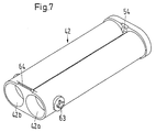
- the receptacle preferably consists of metal and thereby protects the containers of the insert, such as foil bags, in the recording against unwanted mechanical External influences.
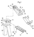
- a dental hand-held device 10 for impression materials is shown in the figures shown, which consists of a basic housing 12, a housing attachment 14 and a double piston 16.
- a disposable insert 18 can be introduced, which consists of two with different components the impression material filled for dental purposes
- Foil bags 20, a head piece 22 and one static mixer 24, the head piece 22nd Includes lines that provide a flow connection between produce the foil bags 20 and the static mixer 24.
- the basic housing 14 is constructed like a pistol and comprises a handle 26 and a hand lever 28.
- Im Housing head 30 of the basic housing 12 are guides 32 provided for the double piston 16. In the guides 32 the double piston 16 is movably supported.
- the lever 32 is inserted into the guides 32 via the hand lever 28 Double piston 16 in its direction of action in Press forwards towards housing attachment 14 of the hand lever 28 driven.
- the housing head 30 has a groove 34 on the end face into which the rear part of the housing attachment 14 engages.
- the housing attachment 14 has a Guide wall 36 which is adapted to the groove 34.
- the housing attachment 14 is hood-shaped. Between the two side walls 38 and 40 of the housing attachment 14 is a two cylindrical, to the filled Foil bags 20 adapted chambers 42a, 42b Recording 42 pivotally mounted.
- the receptacle 42 is about a transverse pivot axis in the area of its rear end adjacent to the Guide wall 36 from an operating position, see 3, in an open position, see Fig. 1, pivotable, where the swivel angle is less than 90 ° is, but in particular is up to 15 °.
- the front end of the receptacle 42 is for insertion and removal the film bag 20 of the insert 18 open and in the end area to the head piece 22 of the disposable insert 18 adjusted.
- the rear end of the receptacle 42 is Retraction of the two pistons 44 of the double piston 16 also openly trained.
- the pistons 44 are on the Chambers 42a and 42b adapted.
- the receptacle 42 is replaced by a Locking device 46 held.
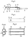
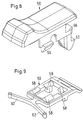
- the locking device 46 is designed in two parts, like this is shown in detail in Figs. 8 and 9.
- the locking device 46 consists of an upper Part, namely a slidable along an axis 48 Button 50, which is provided with a holding means 52, that in a recess 54 at the upper end region of the receptacle 42 engages.
- the button 50 overlaps associated locking and guiding means 56 and 58 in one Bearing part 60, which below the housing attachment 14th is arranged in an associated recess.
- the button 50 is, as mentioned above, along the axis 48 displaceable on the housing attachment 14, so that the Holding means 52 in the recess 54 of the receptacle 42 can be brought in and out.
- the bearing part 60 is biased forward by two spring arms 62. about the locking and guiding means 58 of the bearing part 60 hence the button 50 biased forward. against the button 50 and thus the holding means can be preloaded 52 can be moved out of the recess 54.
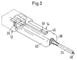
- the Housing attachment 14 partially inserted into the receptacle 42 Disposable insert 18 in the area of Nozzle of the static mixer 24 distal end area.
- this part of the housing attachment 14 is this adapted to the disposable insert 18, whereby a play-free storage of the disposable insert 18 in the operating position the recording 42 is guaranteed.
- the components of the film bags 20 are printed via the lines in the header 22 in the static Mixer 24 pressed, mixed there and over the nozzle of the static mixer 24 in the treatment area applied.
- the pistons 44 are in a known manner in their starting position outside the housing attachment 14 proceed.
- the holding means 42 By pulling the button back 50 the holding means 42 from the recess 54 of the receptacle 42 process and thus released.
- the center of gravity now in front as a result of the compressed Foil bag 20 as well as that in the rear Area arranged bearings 63 of the receptacle 42 it automatically folds down to the rear Area a projection 64 is guided over a latch 66.
- the recording is in this position - open position fixed by the projection 64 and the catch 66 and the Disposable insert 18 automatically slides out of the receptacle 42 out.
- the Housing attachment 14 at one end at the guide wall 36 a locking means 68, which in an associated Recess 70 in the base housing 12 with attachment of the housing attachment 14 snaps onto the basic housing 12 and the housing attachment 14 on the basic housing 12 releasably fixed.
- the invention is characterized by the simple and quick possibility of changing the disposable insert 18 and by retrofitting known devices with the housing attachment 14 of the handheld device 10 of the invention. Operation is by the locking means greatly simplified, with little effort can be solved again.
Abstract
Description
Die Erfindung betrifft ein Handgerät zum Mischen und Ausbringen einer viskosen Flüssigkeit gemäß der im Oberbegriff des Patentanspruches 1 angegebenen Art.The invention relates to a handheld device for mixing and Apply a viscous liquid according to the im Preamble of claim 1 specified type.
Ein derartiges Handgerät ist beispielsweise aus der EP 0 252 401 B1 bekannt und weist einen pistolenartigen Grundaufbau auf. Das Gehäuse umfaßt einen Griff sowie einen Handhebel über den ein im Gehäuse geführter und verfahrbar gelagerter Doppelkolben angetrieben wird. Zum Mischen zweier Komponenten zu einer viskosen Flüssigkeit und Ausbringen dieser Flüssigkeit wird der Kolben in eine Aufnahme in einem lösbar mit dem Gehäuse verbundenen Gehäuseaufsatz verfahren, in der die Behältnisse der Komponenten in Form einer Doppelkartusche angeordnet sind. Auf eine Kartusche wirkt dabei jeweils ein Kolben ein. Die Kartuschen sind über Leitungen mit einer Mischeinrichtung, insbesondere einem statischen Mischer, zur Vermischung der beiden Komponenten aus der Doppelkartusche als eine Baueinheit miteinander verbunden und bilden einen Einsatz. Die Aufnahme ist Teil des Gehäuseaufsatzes, der vom Gehäuse entfernt werden kann, um den Einsatz mit den leeren Kartuschen herauszunehmen und einen neuen Einsatz mit vollen Kartuschen einzusetzen.Such a handheld device is for example from the EP 0 252 401 B1 and has a pistol-like Basic structure on. The housing includes a handle as well a hand lever over the one in the housing and movably mounted double piston is driven. For mixing two components into a viscous liquid and dispensing this liquid becomes the piston in a receptacle in a detachable with the housing connected housing attachment in which the containers the components in the form of a double cartridge are arranged. Each acts on a cartridge a piston. The cartridges are connected via lines a mixing device, especially a static one Mixer, for mixing the two components from the Double cartridge connected as one unit and form an insert. The recording is part of the Housing attachment that can be removed from the housing, to remove the insert with the empty cartridges and insert a new insert with full cartridges.
Ein Auswechseln durch Herausnahme des ganzen Gehäuseaufsatzes nach dem Betrieb des Handgerätes ist äußerst aufwendig. Dies ist insbesondere von Nachteil, wenn das Handgerät im dentalen Bereich zum Ausbringen und Mischen einer Mehrkomponentenmasse für zahnärztliche Zwecke verwendet wird. Hierbei muß nämlich jedes Mal der gebrauchte Einsatz in die Hand genommen werden, wodurch es zu Verschmutzung der Hände oder der Handschuhe kommen kann. Das Handling des Einsatzes und seiner Kartuschen, insbesondere das Ein- und Ausbringen in die Aufnahme mit dem Lösen und Anbringen des Gehäuseaufsatzes an dem Gehäuse des Handgerätes, ist somit für den zahnärztlichen und zahntechnischen Bereich ungünstig.A replacement by removing the entire housing attachment after operating the handset is extreme complex. This is particularly disadvantageous if that Handheld device in the dental area for spreading and mixing a multi-component mass for dental Purposes. This is because every time the used insert can be taken in hand, thereby hands or gloves are dirty can come. The handling of the insert and its cartridges, in particular the introduction and removal in the Recording with loosening and attaching the housing attachment on the housing of the handheld device is therefore for the dental and dental technology area unfavorable.
Das bekannte Handgerät wird für Mehrweg-Einsätze verwendet. Mittlerweile wurden aber auch Einweg-Einsätze entwickelt, wie sie in der deutschen Patentanmeldung Nr. 197 45 614.6-27 offenbart sind.The known handheld device is used for reusable use. In the meantime, however, there were also one-way operations developed as in the German patent application No. 197 45 614.6-27.
Aufgrund dieser neuen Einweg-Einsätze besteht in der täglichen Praxis, insbesondere bei Zahnärzten, zusätzlicher Bedarf an einfach zu handhabenden Handgeräten, die die Herstellung der Abdruckmasse für zahnärztliche Zwecke im jeweils gewünschten Volumen wesentlich erleichtem. Ein Verkleben der Finger oder zahntechnischen Geräte durch die einzelnen Komponenten beim Handling der Einweg-Einsätze ist dabei unerwünscht.Because of these new disposable inserts, the daily practice, especially with dentists, additional Need for easy-to-use handheld devices, which is the manufacture of the impression material for dental Purposes in the desired volume much easier. Gluing the fingers or dental technology Devices through the individual components during handling disposable inserts are undesirable.
Der Erfindung liegt die Aufgabe zugrunde, ein Handgerät gemäß der im Oberbegriff des Patentanspruches 1 angegebenen Art derart weiterzubilden, daß unter Vermeidung der genannten Nachteile ein einfaches und schnelles Auswechseln der Einsätze gewährleistet wird. Zudem soll ein einfaches Nachrüsten bestehender Geräte mit Gehäuseaufsätzen nach der Erfindung ermöglicht werden.The invention has for its object a handheld device according to the specified in the preamble of claim 1 Kind in such a way that avoidance of the disadvantages mentioned a simple and quick Replacement of the inserts is guaranteed. In addition, should easy retrofitting of existing devices with housing attachments be made possible according to the invention.
Diese Aufgabe wird durch die kennzeichnenden Merkmale des Patentanspruches 1 in Verbindung mit seinen Oberbegriffsmerkmalen gelöst. This task is characterized by the characteristics of claim 1 in connection with its preamble features solved.
Weitere vorteilhafte Ausgestaltungen der Erfindung bilden die Gegenstände der Unteransprüche.Form further advantageous embodiments of the invention the subjects of the subclaims.
Der Erfindung liegt die Erkenntnis zugrunde, daß durch ein Herausschwenken der Aufnahme aus dem Betriebebereich ein Auswechseln des Einsatzes ermöglicht wird, ohne den Gehäuseaufsatz, der exakt mit der Achse der Kolben ausgerichtet sein muß, zu bewegen. Insbesondere durch Rastmittel kann die Aufnahme für den Betrieb des Handgeräts in der Betriebsstellung festgehalten werden, so daß die Kolben unbeeinträchtigt in die Aufnahme zum Ausbringen und Mischen der in den Behältnissen des Einsatzes angeordneten Komponenten der viskosen Flüssigkeit eingreifen können.The invention is based on the finding that through swiveling the receptacle out of the operating area a replacement of the insert is made possible without the housing attachment, which is exactly with the axis of the Piston must be aligned to move. In particular by locking means, the recording for the operation of the Handheld devices are held in the operating position, so that the pistons are undisturbed in the intake for Spreading and mixing the in the containers of the insert arranged components of the viscous liquid can intervene.
Nach der Erfindung ist daher die Aufnahme in dem Gehäuseaufsatz so drehbar gelagert, daß diese gegenüber der Achse um eine Schwenkachse zwischen einer Betriebsstellung, in der die Aufnahme mit der Achse ausgerichtet ist, und einer Offenstellung, in der der Einsatz aus der Aufnahme entfernt bzw. in die Aufnahme eingebracht werden kann, verschwenkbar ist. Zudem ist in dem Gehäuseaufsatz eine lösbare Arretiereinrichtung angeordnet, die die Aufnahme in der Betriebsstellung festhält. Desweiteren sind Mittel vorgesehen, die in der Betriebsstellung den Einsatz in der Aufnahme halten, und dadurch ein Bewegen des Einsatzes relativ zur Aufnahme verhindern.According to the invention is therefore the inclusion in the housing attachment so rotatably mounted that this compared to the Axis about a swivel axis between an operating position, in which the recording is aligned with the axis and an open position in which the stake out removed from the receptacle or introduced into the receptacle can be pivoted. In addition, is in the housing attachment a releasable locking device is arranged, which holds the recording in the operating position. Furthermore funds are provided in the operating position keep the insert in the receptacle, and thereby moving the insert relative to the recording prevent.
Hierdurch wird auf einfache Weise ein schnelles Auswechseln des Einsatzes durch Abklappen der Aufnahme ermöglicht. Der Einsatz kann durch selbsttätiges Herausgleiten aus der Aufnahme entfernt werden. Ein Berühren des unter Umständen mit der viskosen Flüssigkeit verschmutzten Bereiches der Ausbringöffnung nach der Mischeinrichtung ist nicht mehr notwendig. This makes it quick and easy to replace of the insert by folding down the holder. The insert can slide out automatically be removed from the recording. One touch possibly with the viscous liquid contaminated area of the discharge opening after the Mixing device is no longer necessary.
Um eine definierte Anordnung des Behältnisses in der Aufnahme zu gewährleisten, ist die Aufnahme an die Form des Einsatzes angepaßt.To a defined arrangement of the container in the To ensure admission is the admission to the form adapted to the application.
Gemäß einer Ausführungsform der Erfindung ist die Aufnahme in ihrer Offenstellung, insbesondere über Rastmittel fixierbar, wodurch verhindert wird, daß sich während des Entfernens des Einsatzes die Aufnahme bewegt, und dadurch das Auswechseln des Einsatzes beeinträchtigt wird.According to one embodiment of the invention, the recording in their open position, especially via locking means fixable, which prevents moves the receptacle while removing the insert, and this affects the replacement of the insert becomes.
Vorzugsweise ist die Aufnahme über einen vorbestimmten Winkel kleiner als 90°, insbesondere bis zu 15° zur Achse, aus der Betriebsstellung in die Offenstellung verschwenkbar. Dieser Bereich ist ausreichend, um ein selbsttätiges Herausgleiten des Einsatzes aus der Aufnahme zu erreichen und zudem die Voraussetzungen für einen kleinbauenden Gehäuseaufsatz zu schaffen.The intake is preferably above a predetermined one Angles smaller than 90 °, in particular up to 15 ° to Axis, from the operating position to the open position pivotable. This area is sufficient to one the insert slides out of the holder automatically to achieve and also the requirements for to create a small housing attachment.
Dies kann weiterhin dadurch optimiert werden, indem gemäß einer weiteren Ausführungsform der Erfindung die Schwenkachse im Bereich des dem Kolben zugewandten Endes der Aufnahme angeordnet ist.This can be further optimized by according to a further embodiment of the invention Swivel axis in the area of the end facing the piston the recording is arranged.
Gemäß einer Ausführungsform der Erfindung umgreift in der Betriebsstellung der Gehäuseaufsatz das dem Kolben entfernt gelegene Ende der Aufnahme sowie zumindest einen Teil des Einsatzes derart, daß dieser in der Aufnahme festgelegt und in der Offenstellung freigegeben ist. Durch Verschwenken der Aufnahme wird somit der Einsatz in der Aufnahme für den Betrieb fixiert - Betriebsstellung - sowie für das Auswechseln freigegeben - Offenstellung . Dieser Teil des Gehäuseaufsatzes ist somit auf einfache Weise das Mittel, um den Einsatz in der Betriebsstellung in der Aufnahme zu halten. According to one embodiment of the invention, encompasses in the operating position of the housing attachment to the piston distant end of the recording and at least one Part of the use in such a way that this in the recording fixed and released in the open position is. By pivoting the receptacle Use fixed in the holder for operation - operating position - and released for replacement - Open position. This part of the housing attachment is thus the means to use in a simple manner to keep the operating position in the recording.
Um eine möglichst spielfreie Lagerung des Einsatzes in der Aufnahme in der Betriebstellung zu erreichen, ist der den Einsatz in der Betriebsstellung umgreifende Teil des Gehäuseaufsatzes zumindest bereichsweise an den Einsatz angepaßt.In order to store the insert as free of play as possible can be reached in the operating position which encompasses the use in the operating position Part of the housing attachment at least in some areas adapted the use.
Vorzugsweise besteht die Aufnahme aus Metall und schützt dadurch die Behältnisse des Einsatzes, wie Folienbeutel, in der Aufnahme vor ungewollten mechanischen Einwirkungen von außen.The receptacle preferably consists of metal and thereby protects the containers of the insert, such as foil bags, in the recording against unwanted mechanical External influences.
Weitere Vorteile und Merkmale bildet die folgende Beschreibung einer Ausführungsform der Erfindung in Zusammenhang mit der Zeichnung. Es zeigen:
- Fig. 1
- eine perspektivische Explosionsdarstellung der einzelnen Teile des Handgerätes nach der Erfindung mit einem Einwegeinsatz für die Komponenten;
- Fig. 2
- eine perspektivische Darstellung des Gehäuseaufsatzes des Handgerätes von Fig. 1 in der Betriebsstellung;
- Fig. 3
- eine Längsschnittansicht durch den Gehäuseaufsatz von Fig. 2;
- Fig. 4
- eine vergrößerte Seitenansicht der Aufnahme von Fig. 3;
- Fig. 5
- eine Längsschnittansicht der Aufnahme von Fig. 4;
- Fig. 6
- eine Querschnittsansicht der Aufnahme von Fig. 5;
- Fig. 7
- eine perspektivische Ansicht der Aufnahme;
- Fig. 8
- eine perspektivische Ansicht des oberen Teils der Arretiereinrichtung; und
- Fig. 9
- eine perspektivische Ansicht des anderen Teils der Arretiereinrichtung.
- Fig. 1
- a perspective exploded view of the individual parts of the handheld device according to the invention with a disposable insert for the components;
- Fig. 2
- a perspective view of the housing attachment of the handheld device of Figure 1 in the operating position.
- Fig. 3
- a longitudinal sectional view through the housing attachment of Fig. 2;
- Fig. 4
- an enlarged side view of the recording of Fig. 3;
- Fig. 5
- a longitudinal sectional view of the receptacle of Fig. 4;
- Fig. 6
- a cross-sectional view of the receptacle of Fig. 5;
- Fig. 7
- a perspective view of the recording;
- Fig. 8
- a perspective view of the upper part of the locking device; and
- Fig. 9
- a perspective view of the other part of the locking device.
In den Figuren ist ein dentales Handgerät 10 für Abdruckmassen
dargestellt, das aus einem Grundgehäuse 12,
einem Gehäuseaufsatz 14 sowie einem Doppelkolben 16 besteht.
In den Gehäuseaufsatz 14 ist ein Einwegeinsatz
18 einbringbar, der aus zwei mit unterschiedlichen Komponenten
der Abdruckmasse für zahnärztliche Zwecke gefüllten
Folienbeuteln 20, einem Kopfstück 22 und einem
statischen Mischer 24 besteht, wobei das Kopfstück 22
Leitungen umfaßt, die eine Strömungsverbindung zwischen
den Folienbeuteln 20 und dem statischen Mischer 24 herstellen.A dental hand-held
Das Grundgehäuse 14 ist pistolenartig aufgebaut und umfaßt
einen Handgriff 26 sowie einen Handhebel 28. Im
Gehäusekopf 30 des Grundgehäuses 12 sind Führungen 32
für den Doppelkolben 16 vorgesehen. In den Führungen 32
ist der Doppelkolben 16 verfahrbar gelagert.The
Über den Handhebel 28 wird der in die Führungen 32 eingebrachte
Doppelkolben 16 in seine Wirkrichtung in
Richtung nach vorne in den Gehäuseaufsatz 14 mit Drücken
des Handhebeis 28 angetrieben.The
Der Gehäusekopf 30 ist stirnseitig mit einer Nut 34
versehen, in die der hintere Teil des Gehäuseaufsatzes
14 eingreift. Hierfür weist der Gehäuseaufsatz 14 eine
Führungswandung 36 auf, die an die Nut 34 angepaßt ist. The
Der Gehäuseaufsatz 14 ist haubenartig ausgebildet. Zwischen
den zwei Seitenwandungen 38 und 40 des Gehäuseaufsatzes
14 ist eine zwei zylindrische, an die gefüllten
Folienbeutel 20 angepaßte Kammern 42a, 42b aufweisende
Aufnahme 42 verschwenkbar gelagert.The
Die Aufnahme 42 ist um eine quer verlaufende Schwenkachse
im Bereich ihres hinteren Endes benachbart der
Führungswandung 36 aus einer Betriebsstellung, siehe
Fig. 3, in eine Offenstellung, siehe Fig. 1, verschwenkbar,
wobei der Schwenkwinkel kleiner als 90°
ist, insbesondere aber bis zu 15° beträgt.The
Das vordere Ende der Aufnahme 42 ist zum Ein- und Ausbringen
der Folienbeutel 20 des Einsatzes 18 offen und
im Endbereich an das Kopfstück 22 des Einwegeinsatzes
18 angepaßt. Das hintere Ende der Aufnahme 42 ist zum
Einfahren der beiden Kolben 44 des Doppelkolbens 16
ebenfalls offen ausgebildet. Die Kolben 44 sind an die
Kammern 42a und 42b angepaßt.The front end of the
In der Betriebsstellung wird die Aufnahme 42 durch eine
Arretiereinrichtung 46 festgehalten. Die Arretiereinrichtung
46 ist dabei zweiteilig ausgeführt, wie dies
im einzelnen in den Fig. 8 und 9 dargestellt ist.In the operating position, the
Die Arretiereinrichtung 46 besteht aus einem oberen
Teil, nämlich einen längs einer Achse 48 verschiebbaren
Knopf 50, der mit einem Haltemittel 52 versehen ist,
das in eine Ausnehmung 54 am oberen Endbereich der Aufnahme
42 eingreift. Der Knopf 50 greift über einander
zugeordnete Rast- und Führungsmittel 56 und 58 in ein
Lagerteil 60 ein, das unterhalb des Gehäuseaufsatzes 14
in einer zugeordneten Ausnehmung angeordnet ist. The locking
Der Knopf 50 ist, wie oben erwähnt, entlang der Achse
48 auf dem Gehäuseaufsatz 14 verschiebbar, so daß das
Haltemittel 52 in die Ausnehmung 54 der Aufnahme 42
ein- und ausgebracht werden kann. Das Lagerteil 60 ist
durch zwei Federarme 62 nach vorne vorgespannt. Über
die Rast- und Führungsmittel 58 des Lagerteils 60 ist
daher auch der Knopf 50 nach vorne vorgespannt. Gegen
die Vorspannung kann der Knopf 50 und somit das Haltemittel
52 aus der Ausnehmung 54 verfahren werden.The
Auf der unteren Seite des Haltemittels 52 ist dieses
abgeschrägt, so daß mit Verschwenken der Aufnahme 42 in
die Betriebsstellung das Haltemittel 52 einfach in die
Ausnehmung 54 einschnappt.This is on the lower side of the holding means 52
beveled so that with pivoting the
Wie deutlich der Fig. 2 zu entnehmen ist, umgreift der
Gehäuseaufsatz 14 teilweise den in die Aufnahme 42 eingebrachten
Einwegeinsatz 18 und zwar im Bereich des der
Düse des statischen Mischers 24 entfernt gelegenen Endbereiches.
In diesem Teil des Gehäuseaufsatzes 14 ist
dieser an den Einwegeinsatz 18 angepaßt, wodurch eine
spielfreie Lagerung des Einwegeinsatzes 18 in der Betriebsstellung
der Aufnahme 42 gewährleistet wird.As can clearly be seen in FIG. 2, the
Entlang der Achse 48 werden zum Mischen und Ausbringen
der dentalen Abdruckmasse die Kolben 44 des Doppelkolbens
16 in die zugeordneten Zylinderkammern 42a und 42b
der Aufnahme 42 verfahren, indem der Handhebel 28 abwechselnd
gedrückt und wieder gelöst wird. Mit zunehmendem
Druck werden die Komponenten der Folienbeutel 20
über die Leitungen im Kopfstück 22 in den statischen
Mischer 24 gedrückt, dort vermischt und über die Düse
des statischen Mischers 24 in den Behandlungsbereich
ausgebracht. Along the
Nach Gebrauch werden die Kolben 44 in bekannter Weise
in ihre Ausgangsposition außerhalb des Gehäuseaufsatzes
14 verfahren. Durch Zurückziehen des Knopfes 50 werden
die Haltemittel 42 aus der Ausnehmung 54 der Aufnahme
42 verfahren und diese somit freigegeben. Durch den
nunmehr vorne liegenden Schwerpunkt in Folge der zusammengedrückten
Folienbeutel 20 sowie das in dem hinteren
Bereich angeordnete Lager 63 der Aufnahme 42
klappt diese selbsttätig nach unten, bis im hinteren
Bereich ein Vorsprung 64 über eine Rast 66 geführt ist.
In dieser Position - Offenstellung - ist die Aufnahme
durch den Vorsprung 64 und die Rast 66 fixiert und der
Einwegeinsatz 18 gleitet selbsttätig aus der Aufnahme
42 heraus.After use, the pistons 44 are in a known manner
in their starting position outside the
Auf einfache Weise kann nunmehr für einen neuen Behandlungsfall
ein neuer Einwegeinsatz 18 in die Aufnahme 42
eingebracht werden. Mit Verschwenken der Aufnahme 42
wird der Vorsprung 64 zurück über die Rast 66 geführt.
Die Aufnahme 42 wird dann wieder in die Betriebsstellung
verschwenkt bis das Haltemittel 52 wieder in die
Ausnehmung 54 der Aufnahme 42 einrastet.In a simple way you can now for a new treatment case
a new
Wie im einzelnen der Fig. 3 zu entnehmen ist, weist der
Gehäuseaufsatz 14 an seinem einen Ende bei der Führungswand
36 ein Rastmittel 68 auf, das in eine zugeordnete
Ausnehmung 70 im Grundgehäuse 12 mit Aufsetzen
des Gehäuseaufsatzes 14 auf das Grundgehäuse 12 einschnappt
und den Gehäuseaufsatz 14 auf dem Grundgehäuse
12 lösbar fixiert.As can be seen in detail in FIG. 3, the
Die Erfindung zeichnet sich durch die einfache und
schnelle Möglichkeit des Auswechselns des Einwegeinsatzes
18 sowie durch die Nachrüstbarkeit bekannter Geräte
mit dem Gehäuseaufsatz 14 des Handgeräts 10 nach
der Erfindung aus. Die Bedienung wird durch die Rastmittel
stark vereinfacht, die mit geringem Kraftaufwand
wieder gelöst werden können. The invention is characterized by the simple and
quick possibility of changing the
- 1010th
- HandgerätHandheld device
- 1212th
- GrundgehäuseBasic housing
- 1414
- GehäuseaufsatzHousing attachment
- 1616
- DoppelkolbenDouble piston
- 1818th
- EinwegeinsatzDisposable
- 2020th
- FolienbeutelFoil pouch
- 2222
- KopfstückHeadpiece
- 2424th
- statischer Mischerstatic mixer
- 2626
- HandgriffHandle
- 2828
- HandhebelHand lever
- 3030th
- GehäusekopfHousing head
- 3232
- Führungguide
- 3434
- NutGroove
- 3636
- FührungswandungGuide wall
- 3838
- SeitenwandungSide wall
- 4040
- SeitenwandungSide wall
- 4242
- Aufnahmeadmission
- 42a42a
- zylindrische Kammer - linkscylindrical chamber - left
- 42b42b
- zylindrische Kammer - rechtscylindrical chamber - right
- 4444
- Kolbenpiston
- 4646
- ArretiereinrichtungLocking device
- 4848
- Achseaxis
- 5050
- Knopfstud
- 5252
- HaltemittelHolding means
- 5454
- AusnehmungRecess
- 5656
- Rast- und Führungsmittel des KnopfesLocking and guiding means of the button
- 5858
- Rast- und Führungsmittel des LagerteilsLatching and guiding means of the bearing part
- 6060
- LagerteilBearing part
- 6262
- FederarmeSpring arms
- 6363
- Lagercamp
- 6464
- Vorsprunghead Start
- 6666
- RastRest
- 6868
- RastmittelLocking means
- 7070
- AusnehmungRecess
Claims (11)
Applications Claiming Priority (2)
| Application Number | Priority Date | Filing Date | Title |
|---|---|---|---|
| DE19916887 | 1999-04-14 | ||
| DE19916887A DE19916887A1 (en) | 1999-04-14 | 1999-04-14 | Handheld device for mixing and dispensing a viscous liquid |
Publications (1)
| Publication Number | Publication Date |
|---|---|
| EP1044727A2 true EP1044727A2 (en) | 2000-10-18 |
Family
ID=7904566
Family Applications (1)
| Application Number | Title | Priority Date | Filing Date |
|---|---|---|---|
| EP00103372A Withdrawn EP1044727A2 (en) | 1999-04-14 | 2000-02-23 | Hand-held apparatus for mixing and applying a viscous material |
Country Status (2)
| Country | Link |
|---|---|
| EP (1) | EP1044727A2 (en) |
| DE (1) | DE19916887A1 (en) |
Cited By (2)
| Publication number | Priority date | Publication date | Assignee | Title |
|---|---|---|---|---|
| EP1795145A1 (en) * | 2005-12-06 | 2007-06-13 | 3M Innovative Properties Company | Dispensing cartridge with grip |
| DE102008028246A1 (en) * | 2008-06-16 | 2009-12-24 | Henkel Ag & Co. Kgaa | output device |
Families Citing this family (1)
| Publication number | Priority date | Publication date | Assignee | Title |
|---|---|---|---|---|
| DE10140650A1 (en) * | 2001-08-18 | 2003-02-27 | Wella Ag | Dispenser esp. for cream hair colorant etc. has housing with two chambers for different materials, each with dispensing piston and actuating lever |
Citations (1)
| Publication number | Priority date | Publication date | Assignee | Title |
|---|---|---|---|---|
| EP0252401B1 (en) | 1986-07-07 | 1990-10-10 | Wilhelm A. Keller | Dispensing device for cartridges |
-
1999
- 1999-04-14 DE DE19916887A patent/DE19916887A1/en not_active Withdrawn
-
2000
- 2000-02-23 EP EP00103372A patent/EP1044727A2/en not_active Withdrawn
Patent Citations (1)
| Publication number | Priority date | Publication date | Assignee | Title |
|---|---|---|---|---|
| EP0252401B1 (en) | 1986-07-07 | 1990-10-10 | Wilhelm A. Keller | Dispensing device for cartridges |
Cited By (4)
| Publication number | Priority date | Publication date | Assignee | Title |
|---|---|---|---|---|
| EP1795145A1 (en) * | 2005-12-06 | 2007-06-13 | 3M Innovative Properties Company | Dispensing cartridge with grip |
| US8714409B2 (en) | 2005-12-06 | 2014-05-06 | 3M Innovative Properties Company | Dispensing cartridge |
| DE102008028246A1 (en) * | 2008-06-16 | 2009-12-24 | Henkel Ag & Co. Kgaa | output device |
| DE102008028246B4 (en) * | 2008-06-16 | 2015-10-29 | Henkel Ag & Co. Kgaa | output device |
Also Published As
| Publication number | Publication date |
|---|---|
| DE19916887A1 (en) | 2000-10-19 |
Similar Documents
| Publication | Publication Date | Title |
|---|---|---|
| DE69935736T2 (en) | EMISSION CARTRIDGES WITH GRADUATED CHAMBER | |
| EP1430959B1 (en) | Device for mixing and dispensing multicomponent products | |
| EP0645124B1 (en) | Syringe for dosing viscous substances, in particular for dental substances | |
| DE2736586C3 (en) | Liquid dispenser | |
| EP0547503A1 (en) | Pipetting device | |
| EP0800798A1 (en) | Applicator device for dental material | |
| DE2736551A1 (en) | PIPETTE | |
| DE4128295A1 (en) | DISCHARGE DEVICE FOR FLOWABLE MEDIA | |
| DE202011002407U1 (en) | Double cartridge, mixer for this and combination of double cartridge and mixer | |
| DE1678342B2 (en) | Device for producing foam balloons | |
| DE3610329A1 (en) | DISPENSING GUN | |
| DE2537022A1 (en) | DEVICE FOR MEASURING, MIXING AND DISPENSING MATERIALS HAVING TWO COMPONENTS | |
| DE3713508C2 (en) | Cartridge for receiving a dispensable medication and injection device therefor | |
| DE19850495A1 (en) | Hand-held device for squeezing substance from flexible bag or cartridge has camping lever which cooperates with eccentric disc of drive mechanism | |
| EP2292337B1 (en) | Caulking gun | |
| EP2826722A1 (en) | Handheld dosing device for powders and pastes | |
| EP0909590B1 (en) | Hand tool for discharging a viscous liquid | |
| DE69921051T2 (en) | Suction device for dispensing liquids | |
| EP0806187B1 (en) | Applicator | |
| EP0699483A1 (en) | Cutting device for extruded masses from cartridges, in particular for mastics and hardening agents | |
| EP1044727A2 (en) | Hand-held apparatus for mixing and applying a viscous material | |
| EP1575445B9 (en) | Device for dispensing a mixed multi-component compound | |
| DE102005061921B4 (en) | Device for storing and discharging fluid substances | |
| EP0589827B1 (en) | Cartridge and bags containing hardenable mortar masses | |
| DE8100807U1 (en) | DEVICE FOR SIMULTANEOUSLY AND DOSED DISPENSING OF PUTTING MATERIALS AND HARDENER PASTE |
Legal Events
| Date | Code | Title | Description |
|---|---|---|---|
| PUAI | Public reference made under article 153(3) epc to a published international application that has entered the european phase |
Free format text: ORIGINAL CODE: 0009012 |
|
| AK | Designated contracting states |
Kind code of ref document: A2 Designated state(s): AT BE CH CY DE DK ES FI FR GB GR IE IT LI LU MC NL PT SE |
|
| AX | Request for extension of the european patent |
Free format text: AL;LT;LV;MK;RO;SI |
|
| STAA | Information on the status of an ep patent application or granted ep patent |
Free format text: STATUS: THE APPLICATION IS DEEMED TO BE WITHDRAWN |
|
| 18D | Application deemed to be withdrawn |
Effective date: 20030902 |
|
| RAP1 | Party data changed (applicant data changed or rights of an application transferred) |
Owner name: ZWINGENBERGER, ARTHUR |
|
| RIN1 | Information on inventor provided before grant (corrected) |
Inventor name: ZWINGENBERGER, ARTHUR |