EP1044639A2 - Low temperature showcase - Google Patents
Low temperature showcase Download PDFInfo
- Publication number
- EP1044639A2 EP1044639A2 EP00302635A EP00302635A EP1044639A2 EP 1044639 A2 EP1044639 A2 EP 1044639A2 EP 00302635 A EP00302635 A EP 00302635A EP 00302635 A EP00302635 A EP 00302635A EP 1044639 A2 EP1044639 A2 EP 1044639A2
- Authority
- EP
- European Patent Office
- Prior art keywords
- air passage
- fan
- passage
- low temperature
- partition
- Prior art date
- Legal status (The legal status is an assumption and is not a legal conclusion. Google has not performed a legal analysis and makes no representation as to the accuracy of the status listed.)
- Granted
Links
Images


Classifications
-
- A—HUMAN NECESSITIES
- A47—FURNITURE; DOMESTIC ARTICLES OR APPLIANCES; COFFEE MILLS; SPICE MILLS; SUCTION CLEANERS IN GENERAL
- A47F—SPECIAL FURNITURE, FITTINGS, OR ACCESSORIES FOR SHOPS, STOREHOUSES, BARS, RESTAURANTS OR THE LIKE; PAYING COUNTERS
- A47F3/00—Show cases or show cabinets
- A47F3/04—Show cases or show cabinets air-conditioned, refrigerated
- A47F3/0404—Cases or cabinets of the closed type
- A47F3/0408—Cases or cabinets of the closed type with forced air circulation
-
- F—MECHANICAL ENGINEERING; LIGHTING; HEATING; WEAPONS; BLASTING
- F25—REFRIGERATION OR COOLING; COMBINED HEATING AND REFRIGERATION SYSTEMS; HEAT PUMP SYSTEMS; MANUFACTURE OR STORAGE OF ICE; LIQUEFACTION SOLIDIFICATION OF GASES
- F25D—REFRIGERATORS; COLD ROOMS; ICE-BOXES; COOLING OR FREEZING APPARATUS NOT OTHERWISE PROVIDED FOR
- F25D17/00—Arrangements for circulating cooling fluids; Arrangements for circulating gas, e.g. air, within refrigerated spaces
- F25D17/04—Arrangements for circulating cooling fluids; Arrangements for circulating gas, e.g. air, within refrigerated spaces for circulating air, e.g. by convection
- F25D17/06—Arrangements for circulating cooling fluids; Arrangements for circulating gas, e.g. air, within refrigerated spaces for circulating air, e.g. by convection by forced circulation
- F25D17/08—Arrangements for circulating cooling fluids; Arrangements for circulating gas, e.g. air, within refrigerated spaces for circulating air, e.g. by convection by forced circulation using ducts
-
- A—HUMAN NECESSITIES
- A47—FURNITURE; DOMESTIC ARTICLES OR APPLIANCES; COFFEE MILLS; SPICE MILLS; SUCTION CLEANERS IN GENERAL
- A47F—SPECIAL FURNITURE, FITTINGS, OR ACCESSORIES FOR SHOPS, STOREHOUSES, BARS, RESTAURANTS OR THE LIKE; PAYING COUNTERS
- A47F3/00—Show cases or show cabinets
- A47F3/04—Show cases or show cabinets air-conditioned, refrigerated
- A47F3/0482—Details common to both closed and open types
-
- F—MECHANICAL ENGINEERING; LIGHTING; HEATING; WEAPONS; BLASTING
- F25—REFRIGERATION OR COOLING; COMBINED HEATING AND REFRIGERATION SYSTEMS; HEAT PUMP SYSTEMS; MANUFACTURE OR STORAGE OF ICE; LIQUEFACTION SOLIDIFICATION OF GASES
- F25D—REFRIGERATORS; COLD ROOMS; ICE-BOXES; COOLING OR FREEZING APPARATUS NOT OTHERWISE PROVIDED FOR
- F25D23/00—General constructional features
- F25D23/06—Walls
- F25D23/065—Details
- F25D23/068—Arrangements for circulating fluids through the insulating material
-
- F—MECHANICAL ENGINEERING; LIGHTING; HEATING; WEAPONS; BLASTING
- F25—REFRIGERATION OR COOLING; COMBINED HEATING AND REFRIGERATION SYSTEMS; HEAT PUMP SYSTEMS; MANUFACTURE OR STORAGE OF ICE; LIQUEFACTION SOLIDIFICATION OF GASES
- F25D—REFRIGERATORS; COLD ROOMS; ICE-BOXES; COOLING OR FREEZING APPARATUS NOT OTHERWISE PROVIDED FOR
- F25D2201/00—Insulation
-
- F—MECHANICAL ENGINEERING; LIGHTING; HEATING; WEAPONS; BLASTING
- F25—REFRIGERATION OR COOLING; COMBINED HEATING AND REFRIGERATION SYSTEMS; HEAT PUMP SYSTEMS; MANUFACTURE OR STORAGE OF ICE; LIQUEFACTION SOLIDIFICATION OF GASES
- F25D—REFRIGERATORS; COLD ROOMS; ICE-BOXES; COOLING OR FREEZING APPARATUS NOT OTHERWISE PROVIDED FOR
- F25D2317/00—Details or arrangements for circulating cooling fluids; Details or arrangements for circulating gas, e.g. air, within refrigerated spaces, not provided for in other groups of this subclass
- F25D2317/06—Details or arrangements for circulating cooling fluids; Details or arrangements for circulating gas, e.g. air, within refrigerated spaces, not provided for in other groups of this subclass with forced air circulation
- F25D2317/063—Details or arrangements for circulating cooling fluids; Details or arrangements for circulating gas, e.g. air, within refrigerated spaces, not provided for in other groups of this subclass with forced air circulation with air guides
-
- F—MECHANICAL ENGINEERING; LIGHTING; HEATING; WEAPONS; BLASTING
- F25—REFRIGERATION OR COOLING; COMBINED HEATING AND REFRIGERATION SYSTEMS; HEAT PUMP SYSTEMS; MANUFACTURE OR STORAGE OF ICE; LIQUEFACTION SOLIDIFICATION OF GASES
- F25D—REFRIGERATORS; COLD ROOMS; ICE-BOXES; COOLING OR FREEZING APPARATUS NOT OTHERWISE PROVIDED FOR
- F25D2317/00—Details or arrangements for circulating cooling fluids; Details or arrangements for circulating gas, e.g. air, within refrigerated spaces, not provided for in other groups of this subclass
- F25D2317/06—Details or arrangements for circulating cooling fluids; Details or arrangements for circulating gas, e.g. air, within refrigerated spaces, not provided for in other groups of this subclass with forced air circulation
- F25D2317/066—Details or arrangements for circulating cooling fluids; Details or arrangements for circulating gas, e.g. air, within refrigerated spaces, not provided for in other groups of this subclass with forced air circulation characterised by the air supply
-
- F—MECHANICAL ENGINEERING; LIGHTING; HEATING; WEAPONS; BLASTING
- F25—REFRIGERATION OR COOLING; COMBINED HEATING AND REFRIGERATION SYSTEMS; HEAT PUMP SYSTEMS; MANUFACTURE OR STORAGE OF ICE; LIQUEFACTION SOLIDIFICATION OF GASES
- F25D—REFRIGERATORS; COLD ROOMS; ICE-BOXES; COOLING OR FREEZING APPARATUS NOT OTHERWISE PROVIDED FOR
- F25D2317/00—Details or arrangements for circulating cooling fluids; Details or arrangements for circulating gas, e.g. air, within refrigerated spaces, not provided for in other groups of this subclass
- F25D2317/06—Details or arrangements for circulating cooling fluids; Details or arrangements for circulating gas, e.g. air, within refrigerated spaces, not provided for in other groups of this subclass with forced air circulation
- F25D2317/068—Details or arrangements for circulating cooling fluids; Details or arrangements for circulating gas, e.g. air, within refrigerated spaces, not provided for in other groups of this subclass with forced air circulation characterised by the fans
- F25D2317/0682—Two or more fans
-
- F—MECHANICAL ENGINEERING; LIGHTING; HEATING; WEAPONS; BLASTING
- F25—REFRIGERATION OR COOLING; COMBINED HEATING AND REFRIGERATION SYSTEMS; HEAT PUMP SYSTEMS; MANUFACTURE OR STORAGE OF ICE; LIQUEFACTION SOLIDIFICATION OF GASES
- F25D—REFRIGERATORS; COLD ROOMS; ICE-BOXES; COOLING OR FREEZING APPARATUS NOT OTHERWISE PROVIDED FOR
- F25D2400/00—General features of, or devices for refrigerators, cold rooms, ice-boxes, or for cooling or freezing apparatus not covered by any other subclass
- F25D2400/22—Cleaning means for refrigerating devices
Definitions
- This invention relates to a low temperature showcase.
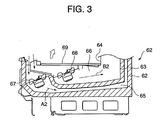
- FIG. 3 illustrates a known low temperature showcase 61 comprising a heat insulating body 62, a heat insulating wall 63 and a storage chamber partition wall 64.
- An outer air passage 65 is formed between the heat insulating body 62 and the heat insulating wall 63
- an inner air passage 66 is formed between the heat insulating wall 63 and the storage chamber partition wall 64.
- the outer passage 65 and the inner passage 66 are completely sectioned so that together they form a complete double structure.
- a fan 67 is mounted in the outer passage 65
- a fan 68 is mounted in the inner passage 66. When each of the fans 67 and 68 is operated, cool air moves within the outer air passage 65 in the direction of arrow A2 and within the inner air passage 66 in the direction of arrow B2. Air is admitted into the outer and inner air passages 65 and 66 through an inlet which can be cleaned and maintained by lifting up deck pan 69 in the direction of the arrow.
- Figure 4 illustrates another known low temperature showcase 81 in which air passage 83 is formed in the bottom portion of a heat insulating body 82.
- Outer air passage 84 and an inner air passage 85 communicate with the air passage 83 and together form a double structure in a back portion of the heat insulating box body 82.
- These outer and inner air passages 84 and 85 are separated by a partition wall 86. Air flows into the bottom air passages 83 through an inlet which can be cleaned and maintained by lifting up deck pan 92 in the direction of the arrow.
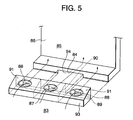
- Figure 5 shows one fan 87 for supplying the outer air passage 84 and two fans 88 for supplying the inner air passage 85 positioned in the bottom passage 83.
- the fans are mounted in substantially the same plane in a row across the width of the low temperature showcase 81.
- a partition 89 is provided in the outlet side of fan casing 93 for the fan 87 which supplies the outer air passage 84 and the fans 88 which supply the inner air passage 85.
- An outer air passage opening 90 and inner air passage openings 91 are formed in the partition member 89.
- the outer air passage 65 is covered by the heat insulating wall 63 and the inner air passage 66 is interrupted by the fan 68 so cleaning and maintaining the drain which flows into the outer and inner air passages 65 and 66 is not easy.
- a low temperature showcase comprising a bottom air passage provided in the bottom portion of a heat insulating body, an outer air passage and an inner air passage which communicate with said bottom air passage, a plurality of fans for supplying air to said outer and inner passages provided in said bottom air passage, a partition provided in an outlet for said fans, an outer air passage opening provided in said partition through which air is blown from a fan into the outer air passage and an inner air passage opening which is provided in the partition through which air is blown from a fan into the inner air passage, at least said outer air passage opening being formed in substantially all of the area in a longitudinal direction of said partition.
- the fans are arranged in the bottom air passage across the width thereof and in substantially the same plane.
- the showcase comprises a bottom portion blowing passage which is provided in a bottom portion of a heat insulating box body, an outer side blowing passage and an inner side blowing passage which are communicated with the bottom portion blowing passage, have a double structure and are provided in a back portion of the heat insulating box body, a plurality of fans for the outer side blowing passage and fans for the inner side blowing passage which are provided in the bottom portion blowing passage so as to be positioned within substantially the same plane, a partition member which is provided in an outlet side of a plurality of fans, an outer side blowing passage opening which is provided in the partition member and through which a blowing wind of the fan for the outer side blowing passage is introduced to the outer side blowing passage, and an inner side blowing passage opening which is provided in the partition member and through which a blowing wind of the fan for the inner side blowing passage is introduced to the inner side blowing passage, wherein at least the outer side blowing passage opening is formed in substantially all around the area in a longitudinal direction of the partition
- a fan casing for mounting the fan is provided, the fan casing having a partition plate which sections between a fan chamber for mounting the fan for the outer side blowing passage and a fan chamber for mounting the fan for the inner side blowing passage, the partition member is constituted by a wall portion of the fan casing, and the outer side blowing passage opening and the inner side blowing passage opening are provided in the wall portion.
- the outer air passage opening is formed in substantially all around the area in a longitudinal direction of the partition member, the outer air passage opening is increased so the blowing static pressure is reduced and it is possible to increase an amount of the wind blowing in the outer air passage. Furthermore, since the bottom portion blowing passage has no dividers in it, its cleaning and the maintenance can be easily performed thereby improving operability.
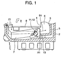
- a low temperature showcase 1 of the present invention which comprises a heat insulating body 2, a heat insulating partition wall 3 provided at an interval with respect to the heat insulating partition wall 3.
- An outer air passage 5 is formed between a back portion of the heat insulating box body 2 and the heat insulating partition wall 3, and an inner air passage 6 is formed between the heat insulating partition wall 3 and the storage chamber partition wall 4.
- a cooling device (not shown) is located in the inner air passage 6.
- a bottom air passage 7 communicates with the outer air passage 5 and the inner air passage 6 is formed in the bottom portion of the heat insulating body 2.
- a deck pan 8 is provided on the bottom passage 7, and a storage chamber 9 on which goods can be displayed is provided above the deck pan 8. In this case, cleaning and a maintenance of a drain which flows into the bottom air passage 7 are performed by lifting up the deck pan 8 in the direction of the arrow.
- each fan 11 for the outer air passage 5 is mounted in air chamber 14 and each fan 12 for the inner air passage 6 is mounted in the fan chamber 15.
- a partition 16 separates the fan chambers 14 and 15 from each other.
- a wall portion 17 which acts as a partition is provided in one side of the heat insulating wall 3 of the fan casing 13.
- An outer air passage opening 18 is formed below the wall portion 17 in all the area of the low temperature showcase 1 in a widthwise direction (a lengthwise direction), and an outer air passage inlet 20 is formed in the heat insulating wall 3 in all the area of the low temperature showcase in a widthwise direction (a longitudinal direction). Further, an inner air passage opening 19 is formed in wall 17 on the surface facing each fan 12 in fan chamber 15. On assembly, the wall portion 17 of the fan casing 13 and the periphery of the outer air passage inlet 20 of the heat insulating wall 3 are brought into contact with each other.
- a current of cool air A1 flows into the outer air passage 5 and a current of cool air B1 flows into the inner side air passage 6.
- cool air in the storage chamber 9 is drawn into the fan casing 13 through suction port or inlet 21 provided in a lower portion of the front surface of the low temperature showcase 1.
- Cool air sucked into the fan chamber 14 for the outer air passage 5 is introduced into the outer air passage 5 through the outer air passage opening 18 and the outer air passage inlet 20 after which it travels upwardly to be blown out from an outer air passage outlet (not shown) into the storage chamber 9.
- each fan chamber 15 cool air sucked into each fan chamber 15 is introduced to the inner air passage 6 through the inner air passage opening 19 after which it travels upwardly where it is cooled via the cooling device (not shown) and blown out from an inner side blowing passage outlet (not shown) into the storage chamber 9.
- the outer air passage opening 18 is formed in all the area in the longitudinal direction of the wall portion 17, the outer air passage opening 18 is enlarged so blowing static pressure is reduced and it is possible to increase the blowing amount of the outer air passage 5. Further, since the bottom blowing passage 7 has no partition or dividers in it, it is easy to clean and maintain thereby improving operability.
- the heat insulating wall 3 is provided between the outer air passage 5 and the inner air passage 6, it may be a partition wall.
- the opening for the outer side air passage is formed in substantially all of the area of the partition member in the longitudinal direction, the opening for the outer air passage is enlarged so the blowing static pressure is reduced and it is possible to increase the amount of blown air in the outer air passage. Further, since the bottom portion air passage does not have any partitions in it, it is easy to clean and maintain so its operability is improved.
Landscapes
- Engineering & Computer Science (AREA)
- Physics & Mathematics (AREA)
- Thermal Sciences (AREA)
- Chemical & Material Sciences (AREA)
- Combustion & Propulsion (AREA)
- Mechanical Engineering (AREA)
- General Engineering & Computer Science (AREA)
- Freezers Or Refrigerated Showcases (AREA)
- Cold Air Circulating Systems And Constructional Details In Refrigerators (AREA)
- Devices For Indicating Variable Information By Combining Individual Elements (AREA)
Abstract
Description
Claims (4)
- A low temperature showcase comprising a bottom air passage (7) which is provided in the bottom portion of a heat insulating body (2), an outer air passage (5) and an inner air passage (6) which communicate with said bottom air passage (7), a plurality of fans (11,12) for the outer and inner passage (5,6) provided in said bottom blowing passage (7), a partition (16) provided in an outlet for said fans (11,12), an outer air passage opening (18) provided in the partition (16) through which air is blown from a fan (11) into the outer air passage (5) and an inner air passage opening (19) which is provided in the partition (16) through which air is blown from a fan (12) into the inner air passage (6), at least said outer air passage opening (18) being formed in substantially all of the area in a longitudinal direction of said partition (16).
- A low temperature showcase as claimed in claim 1 wherein the fans (11,12) are mounted in a casing (13) provided with a partition (16) which separates each fan chamber (15) for each fan (12) for the outer air passage (5) from fan chamber (14) for the fan (11) for the inner air passage (6), said partition (16) comprising a wall portion (17) of the fan casing (13), the outer air passage (5) opening and the inner air passage opening being provided in said wall portion (17).
- A low temperature showcase as claimed in claim 1 or claim 2 wherein the fans are arranged in the bottom air passage (7) across the width thereof and in substantially the same plane.
- A low temperature showcase as claimed in any preceding claim wherein the inner and outer air passages (5,6) have a double structure and are provided in a back portion of the heat insulating body (2).
Applications Claiming Priority (2)
| Application Number | Priority Date | Filing Date | Title |
|---|---|---|---|
| JP09137799A JP4033576B2 (en) | 1999-03-31 | 1999-03-31 | Low temperature showcase |
| JP9137799 | 1999-03-31 |
Publications (3)
| Publication Number | Publication Date |
|---|---|
| EP1044639A2 true EP1044639A2 (en) | 2000-10-18 |
| EP1044639A3 EP1044639A3 (en) | 2001-03-14 |
| EP1044639B1 EP1044639B1 (en) | 2004-06-02 |
Family
ID=14024691
Family Applications (1)
| Application Number | Title | Priority Date | Filing Date |
|---|---|---|---|
| EP00302635A Expired - Lifetime EP1044639B1 (en) | 1999-03-31 | 2000-03-29 | Low temperature showcase |
Country Status (6)
| Country | Link |
|---|---|
| EP (1) | EP1044639B1 (en) |
| JP (1) | JP4033576B2 (en) |
| KR (1) | KR100341984B1 (en) |
| CN (1) | CN1148136C (en) |
| ES (1) | ES2219269T3 (en) |
| TW (1) | TW466326B (en) |
Cited By (3)
| Publication number | Priority date | Publication date | Assignee | Title |
|---|---|---|---|---|
| WO2004032689A1 (en) * | 2002-10-04 | 2004-04-22 | Carrier Commercial Refrigeration, Inc. | Display case air duct partitioned for individual fans |
| US9782019B2 (en) | 2013-03-12 | 2017-10-10 | Hussmann Corporation | Refrigerated merchandiser with pivotal shelf |
| CN107356038A (en) * | 2017-07-18 | 2017-11-17 | 深圳市中科智诚科技有限公司 | A kind of refrigerating equipment with automatic de-icing and purification odor function |
Families Citing this family (3)
| Publication number | Priority date | Publication date | Assignee | Title |
|---|---|---|---|---|
| US10477986B2 (en) | 2016-01-11 | 2019-11-19 | Hussmann Corporation | Fan plenum assembly and attachment in a merchandiser |
| CN106766538B (en) * | 2017-03-13 | 2023-04-21 | 广东维诺电器有限公司 | A synchronous cycle dual temperature zone wine cabinet or freezer |
| CN209893732U (en) * | 2018-04-13 | 2020-01-03 | 青岛海尔电冰箱有限公司 | Refrigerator with specific distance between lowermost storage compartment and bottom wall of refrigerator body |
Family Cites Families (3)
| Publication number | Priority date | Publication date | Assignee | Title |
|---|---|---|---|---|
| US4361012A (en) * | 1980-05-01 | 1982-11-30 | Tyler Refrigeration Corporation | Energy efficient refrigerated merchandiser display case |
| DE8137245U1 (en) * | 1981-12-21 | 1982-06-24 | Hoogstraal AG, 8634 Hombrechtikon | AIR CONDITIONED COUNTER |
| JPH02101368A (en) * | 1988-10-06 | 1990-04-13 | Sanyo Electric Co Ltd | Method of operating low temperature show case |
-
1999
- 1999-03-31 JP JP09137799A patent/JP4033576B2/en not_active Expired - Lifetime
- 1999-12-07 TW TW088121353A patent/TW466326B/en not_active IP Right Cessation
-
2000
- 2000-03-23 CN CNB001043749A patent/CN1148136C/en not_active Expired - Fee Related
- 2000-03-29 EP EP00302635A patent/EP1044639B1/en not_active Expired - Lifetime
- 2000-03-29 ES ES00302635T patent/ES2219269T3/en not_active Expired - Lifetime
- 2000-03-30 KR KR1020000016378A patent/KR100341984B1/en not_active Expired - Fee Related
Cited By (4)
| Publication number | Priority date | Publication date | Assignee | Title |
|---|---|---|---|---|
| WO2004032689A1 (en) * | 2002-10-04 | 2004-04-22 | Carrier Commercial Refrigeration, Inc. | Display case air duct partitioned for individual fans |
| US9782019B2 (en) | 2013-03-12 | 2017-10-10 | Hussmann Corporation | Refrigerated merchandiser with pivotal shelf |
| CN107356038A (en) * | 2017-07-18 | 2017-11-17 | 深圳市中科智诚科技有限公司 | A kind of refrigerating equipment with automatic de-icing and purification odor function |
| CN107356038B (en) * | 2017-07-18 | 2020-07-31 | 瑞安市建宇食品机械加工厂 | Refrigeration equipment with automatic deicing and peculiar smell purification functions |
Also Published As
| Publication number | Publication date |
|---|---|
| EP1044639A3 (en) | 2001-03-14 |
| KR100341984B1 (en) | 2002-07-02 |
| TW466326B (en) | 2001-12-01 |
| JP2000283629A (en) | 2000-10-13 |
| JP4033576B2 (en) | 2008-01-16 |
| CN1268656A (en) | 2000-10-04 |
| EP1044639B1 (en) | 2004-06-02 |
| KR20000063060A (en) | 2000-10-25 |
| CN1148136C (en) | 2004-05-05 |
| ES2219269T3 (en) | 2004-12-01 |
Similar Documents
| Publication | Publication Date | Title |
|---|---|---|
| US20040177635A1 (en) | Showcase | |
| KR970022103A (en) | Refrigerator | |
| EP1044639B1 (en) | Low temperature showcase | |
| US5046328A (en) | Refrigeration apparatus with article preserving and displaying chamber | |
| JP2006242449A (en) | Showcase | |
| JP2002257454A (en) | Electric refrigerator | |
| KR100423973B1 (en) | Outdoor Unit of Air Conditioner | |
| JP2007163020A (en) | Showcase | |
| KR100202606B1 (en) | Circulation apparatus for cold chamber cool air of refrigerator | |
| KR950009192A (en) | Show case | |
| JPH06123544A (en) | Showcase ventilation passage | |
| KR100374562B1 (en) | Cool air duct member for refrigerator | |
| JP2002081840A (en) | refrigerator | |
| JP2006258323A (en) | Showcase | |
| KR200221130Y1 (en) | Cold air circulation structure in the refrigerator | |
| JP2001221562A (en) | Refrigerated open showcase | |
| JP3702061B2 (en) | Low temperature showcase | |
| KR102671268B1 (en) | Cooling module mounting type showcase | |
| KR200153710Y1 (en) | Cover structure of cold air duct for refrigerator | |
| KR100643163B1 (en) | Open Refrigeration Showcase | |
| KR200221818Y1 (en) | Air conditioner | |
| JP2001221561A (en) | Refrigerated open showcase | |
| JP2009041787A (en) | Open showcase | |
| JPS6023662Y2 (en) | Frozen open case | |
| JP4092140B2 (en) | refrigerator |
Legal Events
| Date | Code | Title | Description |
|---|---|---|---|
| PUAI | Public reference made under article 153(3) epc to a published international application that has entered the european phase |
Free format text: ORIGINAL CODE: 0009012 |
|
| AK | Designated contracting states |
Kind code of ref document: A2 Designated state(s): ES FR GB IT |
|
| AX | Request for extension of the european patent |
Free format text: AL;LT;LV;MK;RO;SI |
|
| PUAL | Search report despatched |
Free format text: ORIGINAL CODE: 0009013 |
|
| AK | Designated contracting states |
Kind code of ref document: A3 Designated state(s): AT BE CH CY DE DK ES FI FR GB GR IE IT LI LU MC NL PT SE |
|
| AX | Request for extension of the european patent |
Free format text: AL;LT;LV;MK;RO;SI |
|
| 17P | Request for examination filed |
Effective date: 20010809 |
|
| AKX | Designation fees paid |
Free format text: ES FR GB IT |
|
| GRAP | Despatch of communication of intention to grant a patent |
Free format text: ORIGINAL CODE: EPIDOSNIGR1 |
|
| GRAS | Grant fee paid |
Free format text: ORIGINAL CODE: EPIDOSNIGR3 |
|
| GRAA | (expected) grant |
Free format text: ORIGINAL CODE: 0009210 |
|
| AK | Designated contracting states |
Kind code of ref document: B1 Designated state(s): ES FR GB IT |
|
| REG | Reference to a national code |
Ref country code: GB Ref legal event code: FG4D |
|
| REG | Reference to a national code |
Ref country code: ES Ref legal event code: FG2A Ref document number: 2219269 Country of ref document: ES Kind code of ref document: T3 |
|
| ET | Fr: translation filed | ||
| PLBE | No opposition filed within time limit |
Free format text: ORIGINAL CODE: 0009261 |
|
| STAA | Information on the status of an ep patent application or granted ep patent |
Free format text: STATUS: NO OPPOSITION FILED WITHIN TIME LIMIT |
|
| 26N | No opposition filed |
Effective date: 20050303 |
|
| PGFP | Annual fee paid to national office [announced via postgrant information from national office to epo] |
Ref country code: GB Payment date: 20090325 Year of fee payment: 10 |
|
| PGFP | Annual fee paid to national office [announced via postgrant information from national office to epo] |
Ref country code: ES Payment date: 20090401 Year of fee payment: 10 |
|
| PGFP | Annual fee paid to national office [announced via postgrant information from national office to epo] |
Ref country code: IT Payment date: 20090317 Year of fee payment: 10 |
|
| PGFP | Annual fee paid to national office [announced via postgrant information from national office to epo] |
Ref country code: FR Payment date: 20090316 Year of fee payment: 10 |
|
| GBPC | Gb: european patent ceased through non-payment of renewal fee |
Effective date: 20100329 |
|
| REG | Reference to a national code |
Ref country code: FR Ref legal event code: ST Effective date: 20101130 |
|
| PG25 | Lapsed in a contracting state [announced via postgrant information from national office to epo] |
Ref country code: FR Free format text: LAPSE BECAUSE OF NON-PAYMENT OF DUE FEES Effective date: 20100331 |
|
| PG25 | Lapsed in a contracting state [announced via postgrant information from national office to epo] |
Ref country code: IT Free format text: LAPSE BECAUSE OF NON-PAYMENT OF DUE FEES Effective date: 20100329 Ref country code: GB Free format text: LAPSE BECAUSE OF NON-PAYMENT OF DUE FEES Effective date: 20100329 |
|
| REG | Reference to a national code |
Ref country code: ES Ref legal event code: FD2A Effective date: 20110415 |
|
| PG25 | Lapsed in a contracting state [announced via postgrant information from national office to epo] |
Ref country code: ES Free format text: LAPSE BECAUSE OF NON-PAYMENT OF DUE FEES Effective date: 20110404 |
|
| PG25 | Lapsed in a contracting state [announced via postgrant information from national office to epo] |
Ref country code: ES Free format text: LAPSE BECAUSE OF NON-PAYMENT OF DUE FEES Effective date: 20100330 |