EP1043936B1 - Method and means for conveying and processing an extruded sausage strand - Google Patents
Method and means for conveying and processing an extruded sausage strand Download PDFInfo
- Publication number
- EP1043936B1 EP1043936B1 EP99956748A EP99956748A EP1043936B1 EP 1043936 B1 EP1043936 B1 EP 1043936B1 EP 99956748 A EP99956748 A EP 99956748A EP 99956748 A EP99956748 A EP 99956748A EP 1043936 B1 EP1043936 B1 EP 1043936B1
- Authority
- EP
- European Patent Office
- Prior art keywords
- conveyor
- strand
- loading station
- hooks
- conveyor chain
- Prior art date
- Legal status (The legal status is an assumption and is not a legal conclusion. Google has not performed a legal analysis and makes no representation as to the accuracy of the status listed.)
- Expired - Lifetime
Links
Images





Classifications
-
- A—HUMAN NECESSITIES
- A22—BUTCHERING; MEAT TREATMENT; PROCESSING POULTRY OR FISH
- A22C—PROCESSING MEAT, POULTRY, OR FISH
- A22C15/00—Apparatus for hanging-up meat or sausages
- A22C15/001—Specially adapted for hanging or conveying several sausages or strips of meat
- A22C15/002—Loops, hooks, cords for suspending single sausages; apparatus for making or conveying loops for sausages
-
- A—HUMAN NECESSITIES
- A22—BUTCHERING; MEAT TREATMENT; PROCESSING POULTRY OR FISH
- A22C—PROCESSING MEAT, POULTRY, OR FISH
- A22C11/00—Sausage making ; Apparatus for handling or conveying sausage products during manufacture
Definitions
- Strands of sausage are made on high speed machines by extruding meat emulsion into an elongated casing.
- the meat-filled casing is then twisted to create sausage links.
- the linked strand is discharged from the sausage making machine.
- Loops of sausage comprising a plurality of links are deposited on moving hooks of a conveyor. The ultimate length of a given strand is determined by the length of the casing being filled.
- EP-498 483-A A system for performing such a method is known from EP-498 483-A.
- the linked and looped sausage strand or strands are periodically removed from the conveyor or otherwise transported to a food processing station which normally cooks, smokes or treats the sausage strand before packaging for final delivery to the consumer.
- a further object of the invention is to provide a method and apparatus for conveying and processing a strand of sausage or other foodstuff which is substantially continuous and which will minimize any interruptions in either the reception of the strand or its subsequent processing.
- a still further object of the invention is to provide a method and apparatus for conveying and processing a strand of sausage which will closely coordinate the reception and processing phases of the operation.
- a still further object of the invention is to provide a method and apparatus for conveying and processing a strand of sausage which will allow the processing phase of the operation to continue even though the reception phase is momentarily interrupted.
- a conveyor for moving the strand from a sausage making machine has J-hooks extending downwardly from a continuous chain conveyor.
- the conveyor picks up the loops of the strand at a loading station immediately adjacent the discharge end of the machine, and conveys the loops to a processing station for smoking or the like.
- the conveyor then moves the loops to an unloading station for removal of the strand from the conveyor, whereupon the conveyor downstream of the unloading station returns to the loading station to pick up additional product.
- a conveyor take-up mechanism is located immediately downstream from the loading station to permit the conveyor to cease movement at the loading station (while the casing on the machine is being replenished) while the conveyor can continue movement in the processing area.
- Sensors and controls interconnect the machine and the conveyor to coordinate the operational functions of each.
- a method of producing and processing a strand of sausage or foodstuff involves producing a linked strand of material, depositing linked loops thereof on the hooks of a moving conveyor, controlling the coordinated activity of the production of the product with the movement of the conveyor; moving the product to and through a processing station, and thence to an unloading station, while periodically stopping the movement of the conveyor and the operation of the machine while continuing the movement of the conveyor through the processing area.
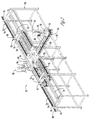
- a conventional sausage making machine 10 has an operator's platform 11 and is positioned upstream of a conveyor 52.
- a food processing station 14 which will be discussed hereafter is located downstream of the machine 10 and immediately downstream from a loading station 16.
- An unloading station 18 is located immediately downstream of the food processing station 14.
- a conveyor chain take up assembly 20 is located immediately downstream of the loading station 16.
- Machine 10 has a conventional linker 22 which discharges a linked product through a discharge horn 24 in the form of a sausage strand 26 (Fig. 10).
- the discharge horn is preferably rotatable, but can be stationary, and is adapted to create sausage loops 28 comprised of several linked sausage elements produced from linker 22.
- the discharge horn 24 is best shown in Fig. 10.
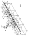
- a support frame 30 (Figs. 2, 3 and 11) slidably supports subframe 32 (Figs. 2 and 3).
- An elongated cylindrical rail 34 is supported on frame 30 upon cross members 35.
- a rectangular rail 36 is spaced from but parallel to rail 34 and is also supported by cross member 35.
- the subframe 32 has wheels 37 (Fig. 3) which movably support the subframe on rails 34 and 36.
- a pair of parallel struts 88 on subframe 32 extend between end members 40 which are supported on four vertical posts 42 (Figs. 2 and 3).
- a horizontal mounting plate 44 (Figs. 2 and 3) is mounted on frame 30.
- a diagonal extending arm 46 extends from a lower portion of frame 30 outwardly towards loading station 16 (Fig. 3) and supports gear box 48.
- a loading motor 50 is also supported by frame member 46 at the loading station.
- An elongated continuous chain conveyor 52 (Figs. 4 and 5), includes a sprocket chain 54 comprised of rotatable chain links 56, chain bushings 58, and U-shaped link elements 60.
- a horizontal shaft 62 extends through link element 60 to support wheel 64 on the opposite ends thereof. Wheels 64 run on the horizontal leg portions of opposite L-shaped tracks 65.
- a hook support 66 rotatably supports bearing 68 which pivotally supports hooks 70 which are thereupon adapted to pivot laterally with respect to the elongated axis of the chain 52.
- Hooks 70 (Fig. 9) are comprised of a vertical shank 72 which has a J-hook portion 74 at its bottom end and a horizontal bar 76 at its upper end.
- chain conveyor 52 has an outgoing segment 78 and a return segment 80 with respect to the loading station 16.
- a sprocket 82 supported on frame 30 at loading station 16 has a loading position 84 (Fig. 10).
- Sprockets 86 and 88 are mounted on frame 30 in spaced relation to sprocket 82 so as to receive the outgoing segment 78 and the return segment 80 of chain 52, respectively.
- Sprockets 86 and 88 are rotatably mounted on frame 30, but are in a fixed position and do not move in a lateral direction.
- Movable sprockets 90 and 92 are rotatably mounted on subframe 32.
- a gear box 94 (Figs. 2 and 3) is mounted on mounting plate 44 and is operatively connected to sprocket 88.
- Master motor 96 is operatively connected to gear box 94.
- motor 96, gear box 94, and sprocket 88 supply the drive power for chain conveyor 52.
- a plurality of slave motors 96A (Fig. 12) to motor 96 can be connected to conveyor 52 to limit the tension on chain 54.
- the food processing station 14 shown in Fig. 1 is comprised of a plurality of conventional food processing units 98, 100, 102 and 104.
- a plurality of sprockets are used in the units 98-104 to move the chain conveyor 52 through each of these food processing units.
- These units include such conventional operation as smoke houses, and the like.
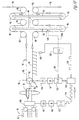
- a rotational drive mechanism 106 is associated with discharge horn 24 to rotate the same in the direction of the arrow shown in Fig. 10 as the strand product 26 is being produced by the machine is discharged therefrom.
- the mechanism 106 is operationally connected to servo motor 108 with gear reducer 110 being located therebetween.
- a servo amplifier 112 is connected to the servo motor 108.
- the servo amplifier 112 is in communication by line 114 to counter/converter 116.
- a proximity switch 118 is located on frame 30 to sense the presence of loops of sausage 28 (or hooks 70) on the conveyor 52.
- Switch 118 is connected by line 120 to the counter/converter 116.
- Variable frequency drive 122 is operationally connected to AC motor 50.
- the AC motor 50 is operationally connected to gear reducer 126 which is operationally connected by convenient means to sprocket 82 at the loading station 16 of the conveyor 52.
- a PLC 128 is connected by line 130 to the variable frequency drive 122.
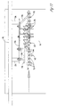
- the unloading station 18 is specifically illustrated in Figs. 11, 12 and 13. With reference to Figs. 12 and 13, a vertically disposed plate 132 is supported from frame 30 by arms 134. A horizontally disposed loop knock-off L-shaped bar 136 having an outwardly extending portion 137 is mounted to plate 132 by support bolts 138. A J-shaped support bracket 140 is also supported by plate 132 in any convenient means. Bracket 140 in turn supports hook-tilting bar 142 (Figs. 12 and 13) and serves to tilt the hooks 70 inwardly towards frame 30 shown by the dotted lines in Fig. 12 and to a position shown by the solid lines in Fig. 13. Bar 142 has an outwardly diagonally extending portion 144 on its free end as best shown in Fig. 13. Bar 145 will engage and pivot hooks 70 back to their normal vertical position if they have not returned to that position by the effects of gravity.
- a conveyor table is located below the unloading station 16 and has an inclined ramp 148 on the upstream end thereof to engage the incoming loops 28 to move them to the inclined position shown best in Fig. 11.
- a cam 152 is located at the loading station 16 to cause the oncoming hooks 70 to tilt outwardly and rearwardly to the position shown in Fig. 6 to better present the hook for receiving the oncoming sausage strand 26 to form loops 28.
- the forming of loops from an oncoming sausage strand is conventional in the art, but the tilting of the hooks 70 in the manner shown in Fig. 6 greatly facilitates this process.
- the sausage making machine 10 produces a sausage strand 26 that is encased within a telescopically compressed casing material which has an extended length of up to 30 feet or so.
- a first length of casing material is filled, it is necessary to stop the operation of the sausage machine, tie off the filled casing material, and provide. a second length of casing material so that the machine can commence operation again. This ordinarily can be accomplished in a very few seconds by an experienced operator.
- the machine 10 and the conveyor 52 need to be carefully coordinated to enhance this process.
- control system set forth in Fig. 10 and described heretofore facilitates the coordination of the sausage making machine 10 and the conveyor 52, and also permits the conveyor 52 to continue taking sausage loops 28 through the food processing station 14 even though the operation at the loading station 16 has been briefly interrupted.
- the sausage making machine 10 communicates with the conveyor 52 through the control system set forth in Fig. 10. Variations of speed and time can be imposed in the interface between these two components.
- the combination of the looper horn 24, servo motor 50 and servo amplifier 112 along with gear reducer 110 are driven at a specified velocity determined by a predetermined ratio of the speed of linker or linker chain 22. Since the rotation of the looper 24 is a servo driven system, there is a feedback from the driven servo motor 108 to the driving servo amplifier 112.
- the information being delivered back to the servo amplifier 112 is a dual square wave (quadrature) pulse train.
- the pulse train because of the gear reduction, is typically 24,000 pulses per every revolution of the looper 24.
- the counter/converter 116 receives pulses from the servo amplifier 110 and starts to send a speed command to the variable frequency drive 122.
- This speed command could be 0-10 VDC, 4-20 mA, or other such forms.
- the magnitude of the speed command and its acceleration and deceleration are driven by the incoming pulse frequency.
- the speed command is interpreted by the variable frequency drive 122 as a specific output frequency which in turn determines the RPM of the AC motor 52, which thereupon influences through the gear reducer 16 the speed of the conveyor hooks 70.
- the conveyor chain 52 and the related hook system also has a feedback source.
- the proximity switch 118 which detects the presence of a hook, transmits a pulse to the counter/converter 116 which compares the count of pulses of the incoming pulse train to the frequency of the proximity switch 118 and makes some adjustments to the speed command to the variable frequency drive 122.
- the foregoing typifies the normal production operation.
- variable frequency drive interrupts the operation of motor 50 so that a hook 70 stops at the 9:00 o'clock position of sprocket 82, as viewed in Fig. 10 so that when operation of the sausage machine 10 is resumed, a hook is immediately in place to commence the grasping of the oncoming sausage strand 26 whereupon a first loop 28 can be commenced without delay.
- the motor 50 is not moving the outgoing segment 78 or the incoming segment 80 of chain 54.
- master motor 96 of the conveyor 52 continues to provide operational power to the chain 54 so that the previously loaded sausage loops 28 move through the food processing station 14 and the unloading station 18.
- the conveyor chain take-up assembly 20 (sometimes called a "buffer") comes into play at that point wherein the subframe 32 moves in an upward direction on the rails 34 and 36. (Fig. 10).
- the dimensions of the subframe 32 are such, and the drive speed of the master motor 36 is such, that the conveyor chain take-up assembly 20 will require sufficient time to move to its take-up position so that a new sausage casing can be installed on machine 10 to permit machine 10 to restart its operation.
- An override circuit in the PLC 128 will override master motor 96 in the event that the machine 10, and motor 50, do not commence to operate before the conveyor chain take-up assembly has reached its maximum displacement.
- the conveyor chain take-up assembly 20 which forms a part of this invention is not novel per se, but its application to this environment is deemed to be novel.
- Sensor 129 communicates with PLC 128 by line 129A to monitor the movement of chain take-up assembly 20 and the lateral position thereof.
- the hooks 70 are tilted outwardly by cam 152 as they arrive at and pass the 9:00 o'clock position of sprocket 82 at the loading station 16. This enhances the grasping of the strand 26 by the hook and facilitates the formation of loops 28. It should also be noted that the movement of hooks 70 at loading station 16 do not intersect the rotation of the looper horn 24 to insure that there is never any mechanical interference between the hooks and the looper horn. Also, the PLC 128 will always cause a hook 70 to stop at the 9:00 o'clock position of sprocket 82 whenever motor 50 ceases to provide power so as to expedite the resumption of loop making as soon as machine 10 becomes operative again.
- Fig. 1 can have superimposed upon itself another set of components directly above the components of Fig. 1 wherein a "two story" system could be simultaneously operated. Similarly, the system of Fig. 1 could have two loading and/or unloading stations to increase the capacity of the system. This would require some alternate spacing of groups of loops 28 on the conveyor 52.
- sausage strands can be easily and quickly produced by conventional sausage making machines 10, and then be provided in a very efficient way to an adjacent conveyor for a quick and efficient delivery to a food processing station, and thence to an unloading station.
- the operation of the sausage making machine and the conveyor are closely coordinated to maximize efficiency, and this efficiency is enhanced by permitting the conveyor to move loops of sausage through the food processing station while the loading station is momentarily out of operation while the sausage machine is being resupplied with sausage casing. It is therefore seen that this invention will achieve at least all of its stated objectives.
Landscapes
- Life Sciences & Earth Sciences (AREA)
- Engineering & Computer Science (AREA)
- Wood Science & Technology (AREA)
- Zoology (AREA)
- Food Science & Technology (AREA)
- Chain Conveyers (AREA)
- Meat, Egg Or Seafood Products (AREA)
- Processing Of Meat And Fish (AREA)
Description
Claims (15)
- A system for processing an elongated strand of food material, comprising, an elongated continuous conveyor chain (52) mounted on a support frame (30) and having at least one strand loading station (16), a plurality of shaped hooks (70) having a normally vertical shank with an upper end secured to said conveyor chain (52) and a lower end terminating in a hook portion, the loading station of the conveyor chain being adapted for location adjacent the discharge station of a strand producing machine to receive loops (28) of the strand on said hooks from the machine, the conveyor chain being disposed in a horizontal plane and having a first portion (78) departing from its loading station (16), and a second portion (80) returning to the loading station, and power means (96) for moving the conveyor chain along a horizontal path on the support frame (30) characterised in that a part of the conveyor chain is adapted to passes through the food processing station (14) and a control system being operatively connected to the conveyor to enable the path of movement of the first and second portions to be non-symmetrical.
- A system of claim 1, wherein the plurality of shaped hooks (70) are J-shaped hooks.
- A system of claim 1 or 2, wherein the control system comprises a moveable chain take-up mechanism (20) and wherein the conveyor chain passes through the moveable chain take-up mechanism to permit segments (78,80) of said conveyor chain (52) to move at different velocities at certain times.
- A system according to claim 3, wherein the velocity of the segment at the loading station can be zero for a period of time.
- A system according to any of the preceding claims, wherein the hooks (70) are mounted to pivot laterally with respect to the longitudinal axis of the conveyor chain.
- A system according to claim 5, wherein a cam element (152) is located at the loading station (16) to pivot the hooks laterally with respect to the longitudinal axis of the chain to facilitate the mounting of a loop on a hook on the chain.
- A system according to any of the preceding claims, wherein a cam element (152) pivots the hooks outwardly towards the machine at the loading station (16) to receive a loop of the strand.
- A system according to any of the preceding claims, wherein a loop removal element (136) is at the unloading station (18) and positioned to engage loops of the strand on the laterally pivoted hook and to cause the engaged loops (28) to slide free from the hooks.
- A system according to any of the preceding claims, wherein the hook portions on the lower ends of the vertical shanks extend diagonally outwardly from a vertical plane passing through the centre axis of the conveyor chain, and extend rearwardly with respect to the direction of travel of the conveyor chain.
- A system according to any of the preceding claims, wherein the control system enables the operating speeds of the machine and the conveyor chain (52) at its loading station (16) to be co-ordinated so that selectively the machine can deliver loops of strand to intermittent hooks (70) on the conveyor chain wherein one or more empty hooks without loops of strands thereon will appear between those hooks that support loops of the strand.
- A system according to any of the preceding claims, wherein the control system is operatively connected to the conveyor chain (52) so that if delivery of a first strand to the loading station (16) is interrupted, the conveyor chain at the loading station will stop in sufficient time so that the next hook (70) for picking up a strand loop will not pass the loading station (16) but will be in position at the loading station to receive the next strand loop when the supply of looped strands recommences.
- A system according to any of the preceding claims, wherein the control system is a take-up mechanism (20) between the loading station and the food processing station so that movement of said conveyor chain through the loading station can be periodically interrupted while movement of the conveyor chain (52) through the food processing station can be continued.
- A system according to claim 2, wherein said J-shaped hook (70) comprises a trunk having an upper end pivotally suspended from said conveyor and having a lower end curved into a finger extending therefrom, said food material being carried at the curve, said J-shaped hook being pivotable about a pivot axis which is non-perpendicular to the direction of movement of said J-shaped hook as conveyed by said conveyor, said finger extending from said trunk at an oblique angle relative to said pivot axis and relative to said direction of movement.
- A method of processing an elongated strand of food material, comprising, producing an elongated food strand, delivering the strand to a loading station of a moving conveyor, loading the strand on the conveyor, transforming the strand into a series of loops as it is loaded on the conveyor, extending and moving the conveyor through a food processing station, periodically interrupting the delivery of the strand to the loading station, stopping the movement of the conveyor at the loading station when the delivery of the strand is interrupted, while continuing to move the conveyor through the food processing station.
- The method of claim 14 comprising the steps of imposing a conveyor take-up assembly between the loading station and the food processing station.
Applications Claiming Priority (3)
| Application Number | Priority Date | Filing Date | Title |
|---|---|---|---|
| US09/182,559 US6086469A (en) | 1998-10-29 | 1998-10-29 | Method and means for conveying and processing an extruded sausage strand |
| US182559 | 1998-10-29 | ||
| PCT/US1999/025321 WO2000025592A1 (en) | 1998-10-29 | 1999-10-28 | Method and means for conveying and processing an extruded sausage strand |
Publications (2)
| Publication Number | Publication Date |
|---|---|
| EP1043936A1 EP1043936A1 (en) | 2000-10-18 |
| EP1043936B1 true EP1043936B1 (en) | 2004-08-25 |
Family
ID=22669003
Family Applications (1)
| Application Number | Title | Priority Date | Filing Date |
|---|---|---|---|
| EP99956748A Expired - Lifetime EP1043936B1 (en) | 1998-10-29 | 1999-10-28 | Method and means for conveying and processing an extruded sausage strand |
Country Status (11)
| Country | Link |
|---|---|
| US (1) | US6086469A (en) |
| EP (1) | EP1043936B1 (en) |
| JP (1) | JP2002528100A (en) |
| KR (1) | KR100372957B1 (en) |
| AR (1) | AR021011A1 (en) |
| AT (1) | ATE274305T1 (en) |
| AU (1) | AU1328600A (en) |
| CA (1) | CA2316247C (en) |
| DE (1) | DE69919678T2 (en) |
| MX (1) | MXPA00006478A (en) |
| WO (1) | WO2000025592A1 (en) |
Cited By (2)
| Publication number | Priority date | Publication date | Assignee | Title |
|---|---|---|---|---|
| EP4578289A1 (en) * | 2023-12-18 | 2025-07-02 | VEMAG Maschinenbau GmbH | Method and device for providing portions of a paste-like food mass, in particular sausages |
| EP4578290A1 (en) * | 2023-12-18 | 2025-07-02 | VEMAG Maschinenbau GmbH | Method and device for providing portions of a pasty food mass, in particular sausages |
Families Citing this family (17)
| Publication number | Priority date | Publication date | Assignee | Title |
|---|---|---|---|---|
| US7134956B2 (en) * | 1999-12-23 | 2006-11-14 | Georgia Tech Research Corporation | Automated feet-gripping system |
| KR100385866B1 (en) * | 2001-02-15 | 2003-06-02 | 일진나노텍 주식회사 | Purifying method of singlewalled carbon nanotubes and thermal treatment apparatus used in the same |
| DE10124719A1 (en) * | 2001-05-19 | 2002-11-21 | Wilhelm Fessmann Gmbh U Co | Supply of individual sausages distributed by switch point to several processing stations |
| US6523462B1 (en) | 2002-06-27 | 2003-02-25 | Alkar-Rapidpak, Inc. | Aligned food processing system |
| US20040072524A1 (en) * | 2002-08-22 | 2004-04-15 | Townsend Engineering Company | Transport device for elongate meat products and method for compensating length changes in a displacing member |
| US8151973B2 (en) * | 2002-11-01 | 2012-04-10 | Kraft Foods Global Brands Llc | Suspension device for linked products |
| US6786321B2 (en) * | 2002-11-01 | 2004-09-07 | Kraft Foods Holdings, Inc. | Independent conveyor system for conveying linked food products |
| US7464806B2 (en) * | 2002-11-01 | 2008-12-16 | Kraft Foods Global Brands Llc | Suspension device for linked products |
| US7735630B2 (en) * | 2002-11-01 | 2010-06-15 | Kraft Foods Global Brands Llc | Suspension device for linked products |
| US7325486B1 (en) * | 2002-12-04 | 2008-02-05 | Alkar-Rapidpak, Inc. | Food processing apparatus and method |
| SI1615613T1 (en) * | 2003-04-18 | 2010-03-31 | Enanta Pharm Inc | Quinoxalinyl macrocyclic hepatitis c serine protease inhibitors |
| US7000816B1 (en) | 2003-09-26 | 2006-02-21 | Alkar-Rapidpak, Inc. | Loading system for elongated strand of food product |
| US7083509B2 (en) * | 2003-10-10 | 2006-08-01 | Alkar-Rapid Pak, Inc. | High capacity food processing system |
| US20100190426A1 (en) * | 2009-01-26 | 2010-07-29 | Kok-Meng Lee | Live bird shackle transfer systems and methods |
| EP2653036B1 (en) * | 2012-04-18 | 2019-04-03 | Albert Handtmann Maschinenfabrik GmbH & Co. KG | Device and method for suspending sausages |
| JP6110194B2 (en) * | 2013-04-17 | 2017-04-05 | ハイテック株式会社 | Apparatus and method for suspending sausage on hook |
| EP3732984B1 (en) | 2019-05-02 | 2024-02-14 | Metalquimia, SAU | Food product treatment plant and method |
Family Cites Families (26)
| Publication number | Priority date | Publication date | Assignee | Title |
|---|---|---|---|---|
| DE236106C (en) * | ||||
| US1973196A (en) * | 1932-05-03 | 1934-09-11 | Baker Perkins Co Inc | Machine for depositing articles or viscous liquids and the like upon trays or in molds carried by a continuously traveling conveyer |
| US2212348A (en) * | 1937-08-14 | 1940-08-20 | Ball Brothers Co | Drive and timing mechanism |
| US2551080A (en) * | 1946-06-28 | 1951-05-01 | American Mach & Foundry | Work station conveying mechanism |
| US2725970A (en) * | 1951-09-26 | 1955-12-06 | Wullschleger August | Transporter |
| US3132373A (en) * | 1961-09-13 | 1964-05-12 | Jr William F Altenpohl | Poultry shackle for overhead conveyor and carriage assembly |
| US3191222A (en) * | 1963-04-22 | 1965-06-29 | Townsend Engineering Co | Machine for encasing sausage and the like |
| US3204844A (en) * | 1962-07-25 | 1965-09-07 | Schmidt Wallace Inc | Method and apparatus for producing wieners |
| US3264679A (en) * | 1963-12-24 | 1966-08-09 | Charles D Moekle | Apparatus for making linked products |
| US3296657A (en) * | 1963-12-24 | 1967-01-10 | Charles D Moekle | Method for making linked products |
| US3494277A (en) * | 1966-10-24 | 1970-02-10 | Union Carbide Corp | Strand unloader |
| US3533495A (en) * | 1968-08-14 | 1970-10-13 | Schmidt Wallace Inc | Apparatus for handling wieners and the like |
| US3850566A (en) * | 1972-12-22 | 1974-11-26 | Beloit Corp | Parison oven having improved discharge station |
| US4233709A (en) * | 1979-06-06 | 1980-11-18 | Townsend Engineering Company | Link cutter |
| DE3536460A1 (en) * | 1985-10-12 | 1987-04-16 | Schnell Maschfab Karl | HANGING DEVICE FOR SAUSAGE CHAINS |
| US5232080A (en) * | 1989-03-10 | 1993-08-03 | Fps Food Processing Systems B.V. | Article handling method and apparatus |
| ES2097129T3 (en) * | 1989-04-22 | 1997-04-01 | Hitec Co Ltd | METHOD AND APPARATUS FOR SUSPENDING WRAPPED PRODUCTS FILLED WITH MATERIAL. |
| DE8912219U1 (en) * | 1989-10-13 | 1989-11-23 | Albert Handtmann Maschinenfabrik GmbH & Co KG, 7950 Biberach | Device for transporting sausages filled into a continuous sausage casing |
| DE9014610U1 (en) * | 1990-10-22 | 1991-06-20 | Albert Handtmann Maschinenfabrik GmbH & Co KG, 7950 Biberach | Device for feeding sausage loops to a smoking stick |
| US5197915A (en) * | 1991-01-25 | 1993-03-30 | Hitec Co., Ltd. | Method and apparatus for suspending a chain of linked |
| US5174428A (en) * | 1991-04-08 | 1992-12-29 | Apv Crepaco Inc. | Confection conveyor system with constant-velocity pick-up section and pausing drop section |
| DE4122370A1 (en) * | 1991-07-05 | 1993-01-07 | Vemag Maschinenbau Gmbh | METHOD FOR HANGING SAUSAGE CHAINS IN LOOPS AND A DEVICE THEREFOR |
| US5183433A (en) * | 1992-02-12 | 1993-02-02 | Townsend Engineering Company | Sausage encasing machine having an improved looper horn |
| US5354230A (en) * | 1993-07-30 | 1994-10-11 | Dec International | Food processing system with simplified loading and transfer |
| JP2657476B2 (en) * | 1995-04-19 | 1997-09-24 | 福留ハム株式会社 | Method for recovering transport hanger, recovery device and return device for transport hanger |
| KR0167655B1 (en) * | 1995-07-29 | 1998-12-01 | 김진곤 | Sausage Maker |
-
1998
- 1998-10-29 US US09/182,559 patent/US6086469A/en not_active Expired - Lifetime
-
1999
- 1999-10-28 CA CA002316247A patent/CA2316247C/en not_active Expired - Lifetime
- 1999-10-28 WO PCT/US1999/025321 patent/WO2000025592A1/en not_active Ceased
- 1999-10-28 AT AT99956748T patent/ATE274305T1/en not_active IP Right Cessation
- 1999-10-28 AU AU13286/00A patent/AU1328600A/en not_active Abandoned
- 1999-10-28 MX MXPA00006478A patent/MXPA00006478A/en unknown
- 1999-10-28 AR ARP990105453A patent/AR021011A1/en unknown
- 1999-10-28 DE DE1999619678 patent/DE69919678T2/en not_active Expired - Lifetime
- 1999-10-28 JP JP2000579059A patent/JP2002528100A/en not_active Withdrawn
- 1999-10-28 EP EP99956748A patent/EP1043936B1/en not_active Expired - Lifetime
- 1999-10-28 KR KR10-2000-7007284A patent/KR100372957B1/en not_active Expired - Fee Related
Cited By (2)
| Publication number | Priority date | Publication date | Assignee | Title |
|---|---|---|---|---|
| EP4578289A1 (en) * | 2023-12-18 | 2025-07-02 | VEMAG Maschinenbau GmbH | Method and device for providing portions of a paste-like food mass, in particular sausages |
| EP4578290A1 (en) * | 2023-12-18 | 2025-07-02 | VEMAG Maschinenbau GmbH | Method and device for providing portions of a pasty food mass, in particular sausages |
Also Published As
| Publication number | Publication date |
|---|---|
| CA2316247A1 (en) | 2000-05-11 |
| US6086469A (en) | 2000-07-11 |
| JP2002528100A (en) | 2002-09-03 |
| CA2316247C (en) | 2007-01-09 |
| KR20010074422A (en) | 2001-08-04 |
| AU1328600A (en) | 2000-05-22 |
| WO2000025592A8 (en) | 2001-07-12 |
| AR021011A1 (en) | 2002-06-12 |
| ATE274305T1 (en) | 2004-09-15 |
| DE69919678T2 (en) | 2005-01-13 |
| EP1043936A1 (en) | 2000-10-18 |
| DE69919678D1 (en) | 2004-09-30 |
| MXPA00006478A (en) | 2003-07-14 |
| WO2000025592A1 (en) | 2000-05-11 |
| KR100372957B1 (en) | 2003-02-25 |
Similar Documents
| Publication | Publication Date | Title |
|---|---|---|
| EP1043935B1 (en) | Method and means for making and conveying an extruded sausage strand | |
| US6086469A (en) | Method and means for conveying and processing an extruded sausage strand | |
| US6786321B2 (en) | Independent conveyor system for conveying linked food products | |
| US8151973B2 (en) | Suspension device for linked products | |
| US20090127072A1 (en) | Suspension device for linked products | |
| US4854440A (en) | Apparatus for transferring articles to a packaging machine conveyor apparatus | |
| US5339942A (en) | Apparatus for introducing articles into a storage device | |
| US6467668B1 (en) | Conveyor chain and system for looped sausage products | |
| US7464806B2 (en) | Suspension device for linked products | |
| MXPA00006110A (en) | Method and means for making and conveying an extruded sausage strand | |
| JPS6023220A (en) | Distribution device |
Legal Events
| Date | Code | Title | Description |
|---|---|---|---|
| PUAI | Public reference made under article 153(3) epc to a published international application that has entered the european phase |
Free format text: ORIGINAL CODE: 0009012 |
|
| AK | Designated contracting states |
Kind code of ref document: A1 Designated state(s): AT BE CH CY DE DK ES FI FR GB GR IE IT LI LU MC NL PT SE |
|
| 17P | Request for examination filed |
Effective date: 20000909 |
|
| 17Q | First examination report despatched |
Effective date: 20020730 |
|
| GRAP | Despatch of communication of intention to grant a patent |
Free format text: ORIGINAL CODE: EPIDOSNIGR1 |
|
| RAP1 | Party data changed (applicant data changed or rights of an application transferred) |
Owner name: DEC INTERNATIONAL, INC. |
|
| GRAS | Grant fee paid |
Free format text: ORIGINAL CODE: EPIDOSNIGR3 |
|
| GRAA | (expected) grant |
Free format text: ORIGINAL CODE: 0009210 |
|
| AK | Designated contracting states |
Kind code of ref document: B1 Designated state(s): AT BE CH CY DE DK ES FI FR GB GR IE IT LI LU MC NL PT SE |
|
| PG25 | Lapsed in a contracting state [announced via postgrant information from national office to epo] |
Ref country code: LI Free format text: LAPSE BECAUSE OF FAILURE TO SUBMIT A TRANSLATION OF THE DESCRIPTION OR TO PAY THE FEE WITHIN THE PRESCRIBED TIME-LIMIT Effective date: 20040825 Ref country code: FR Free format text: LAPSE BECAUSE OF FAILURE TO SUBMIT A TRANSLATION OF THE DESCRIPTION OR TO PAY THE FEE WITHIN THE PRESCRIBED TIME-LIMIT Effective date: 20040825 Ref country code: FI Free format text: LAPSE BECAUSE OF FAILURE TO SUBMIT A TRANSLATION OF THE DESCRIPTION OR TO PAY THE FEE WITHIN THE PRESCRIBED TIME-LIMIT Effective date: 20040825 Ref country code: CY Free format text: LAPSE BECAUSE OF FAILURE TO SUBMIT A TRANSLATION OF THE DESCRIPTION OR TO PAY THE FEE WITHIN THE PRESCRIBED TIME-LIMIT Effective date: 20040825 Ref country code: CH Free format text: LAPSE BECAUSE OF FAILURE TO SUBMIT A TRANSLATION OF THE DESCRIPTION OR TO PAY THE FEE WITHIN THE PRESCRIBED TIME-LIMIT Effective date: 20040825 Ref country code: BE Free format text: LAPSE BECAUSE OF FAILURE TO SUBMIT A TRANSLATION OF THE DESCRIPTION OR TO PAY THE FEE WITHIN THE PRESCRIBED TIME-LIMIT Effective date: 20040825 Ref country code: AT Free format text: LAPSE BECAUSE OF FAILURE TO SUBMIT A TRANSLATION OF THE DESCRIPTION OR TO PAY THE FEE WITHIN THE PRESCRIBED TIME-LIMIT Effective date: 20040825 |
|
| REG | Reference to a national code |
Ref country code: GB Ref legal event code: FG4D |
|
| REG | Reference to a national code |
Ref country code: CH Ref legal event code: EP |
|
| REG | Reference to a national code |
Ref country code: IE Ref legal event code: FG4D |
|
| REF | Corresponds to: |
Ref document number: 69919678 Country of ref document: DE Date of ref document: 20040930 Kind code of ref document: P |
|
| PG25 | Lapsed in a contracting state [announced via postgrant information from national office to epo] |
Ref country code: LU Free format text: LAPSE BECAUSE OF NON-PAYMENT OF DUE FEES Effective date: 20041028 Ref country code: IE Free format text: LAPSE BECAUSE OF NON-PAYMENT OF DUE FEES Effective date: 20041028 |
|
| PG25 | Lapsed in a contracting state [announced via postgrant information from national office to epo] |
Ref country code: MC Free format text: LAPSE BECAUSE OF NON-PAYMENT OF DUE FEES Effective date: 20041031 |
|
| PG25 | Lapsed in a contracting state [announced via postgrant information from national office to epo] |
Ref country code: SE Free format text: LAPSE BECAUSE OF FAILURE TO SUBMIT A TRANSLATION OF THE DESCRIPTION OR TO PAY THE FEE WITHIN THE PRESCRIBED TIME-LIMIT Effective date: 20041125 Ref country code: GR Free format text: LAPSE BECAUSE OF FAILURE TO SUBMIT A TRANSLATION OF THE DESCRIPTION OR TO PAY THE FEE WITHIN THE PRESCRIBED TIME-LIMIT Effective date: 20041125 Ref country code: DK Free format text: LAPSE BECAUSE OF FAILURE TO SUBMIT A TRANSLATION OF THE DESCRIPTION OR TO PAY THE FEE WITHIN THE PRESCRIBED TIME-LIMIT Effective date: 20041125 |
|
| PG25 | Lapsed in a contracting state [announced via postgrant information from national office to epo] |
Ref country code: ES Free format text: LAPSE BECAUSE OF FAILURE TO SUBMIT A TRANSLATION OF THE DESCRIPTION OR TO PAY THE FEE WITHIN THE PRESCRIBED TIME-LIMIT Effective date: 20041206 |
|
| REG | Reference to a national code |
Ref country code: CH Ref legal event code: PL |
|
| PLBE | No opposition filed within time limit |
Free format text: ORIGINAL CODE: 0009261 |
|
| STAA | Information on the status of an ep patent application or granted ep patent |
Free format text: STATUS: NO OPPOSITION FILED WITHIN TIME LIMIT |
|
| REG | Reference to a national code |
Ref country code: IE Ref legal event code: MM4A |
|
| 26N | No opposition filed |
Effective date: 20050526 |
|
| EN | Fr: translation not filed | ||
| PG25 | Lapsed in a contracting state [announced via postgrant information from national office to epo] |
Ref country code: PT Free format text: LAPSE BECAUSE OF NON-PAYMENT OF DUE FEES Effective date: 20050125 |
|
| PGFP | Annual fee paid to national office [announced via postgrant information from national office to epo] |
Ref country code: NL Payment date: 20181017 Year of fee payment: 20 |
|
| PGFP | Annual fee paid to national office [announced via postgrant information from national office to epo] |
Ref country code: DE Payment date: 20181016 Year of fee payment: 20 |
|
| PGFP | Annual fee paid to national office [announced via postgrant information from national office to epo] |
Ref country code: GB Payment date: 20181024 Year of fee payment: 20 Ref country code: IT Payment date: 20181018 Year of fee payment: 20 |
|
| REG | Reference to a national code |
Ref country code: DE Ref legal event code: R071 Ref document number: 69919678 Country of ref document: DE |
|
| REG | Reference to a national code |
Ref country code: NL Ref legal event code: MK Effective date: 20191027 |
|
| REG | Reference to a national code |
Ref country code: GB Ref legal event code: PE20 Expiry date: 20191027 |
|
| PG25 | Lapsed in a contracting state [announced via postgrant information from national office to epo] |
Ref country code: GB Free format text: LAPSE BECAUSE OF EXPIRATION OF PROTECTION Effective date: 20191027 |