EP1043642A2 - Robot system having image processing function - Google Patents
Robot system having image processing function Download PDFInfo
- Publication number
- EP1043642A2 EP1043642A2 EP00303008A EP00303008A EP1043642A2 EP 1043642 A2 EP1043642 A2 EP 1043642A2 EP 00303008 A EP00303008 A EP 00303008A EP 00303008 A EP00303008 A EP 00303008A EP 1043642 A2 EP1043642 A2 EP 1043642A2
- Authority
- EP
- European Patent Office
- Prior art keywords
- image
- posture
- robot
- workpiece
- capturing device
- Prior art date
- Legal status (The legal status is an assumption and is not a legal conclusion. Google has not performed a legal analysis and makes no representation as to the accuracy of the status listed.)
- Granted
Links
Images


Classifications
-
- B—PERFORMING OPERATIONS; TRANSPORTING
- B25—HAND TOOLS; PORTABLE POWER-DRIVEN TOOLS; MANIPULATORS
- B25J—MANIPULATORS; CHAMBERS PROVIDED WITH MANIPULATION DEVICES
- B25J9/00—Program-controlled manipulators
- B25J9/16—Program controls
- B25J9/1694—Program controls characterised by use of sensors other than normal servo-feedback from position, speed or acceleration sensors, perception control, multi-sensor controlled systems, sensor fusion
- B25J9/1697—Vision controlled systems
-
- G—PHYSICS
- G05—CONTROLLING; REGULATING
- G05B—CONTROL OR REGULATING SYSTEMS IN GENERAL; FUNCTIONAL ELEMENTS OF SUCH SYSTEMS; MONITORING OR TESTING ARRANGEMENTS FOR SUCH SYSTEMS OR ELEMENTS
- G05B2219/00—Program-control systems
- G05B2219/30—Nc systems
- G05B2219/37—Measurements
- G05B2219/37553—Two cameras one for coarse scanning, other for fine scanning
-
- G—PHYSICS
- G05—CONTROLLING; REGULATING
- G05B—CONTROL OR REGULATING SYSTEMS IN GENERAL; FUNCTIONAL ELEMENTS OF SUCH SYSTEMS; MONITORING OR TESTING ARRANGEMENTS FOR SUCH SYSTEMS OR ELEMENTS
- G05B2219/00—Program-control systems
- G05B2219/30—Nc systems
- G05B2219/37—Measurements
- G05B2219/37555—Camera detects orientation, position workpiece, points of workpiece
-
- G—PHYSICS
- G05—CONTROLLING; REGULATING
- G05B—CONTROL OR REGULATING SYSTEMS IN GENERAL; FUNCTIONAL ELEMENTS OF SUCH SYSTEMS; MONITORING OR TESTING ARRANGEMENTS FOR SUCH SYSTEMS OR ELEMENTS
- G05B2219/00—Program-control systems
- G05B2219/30—Nc systems
- G05B2219/37—Measurements
- G05B2219/37567—3-D vision, stereo vision, with two cameras
-
- G—PHYSICS
- G05—CONTROLLING; REGULATING
- G05B—CONTROL OR REGULATING SYSTEMS IN GENERAL; FUNCTIONAL ELEMENTS OF SUCH SYSTEMS; MONITORING OR TESTING ARRANGEMENTS FOR SUCH SYSTEMS OR ELEMENTS
- G05B2219/00—Program-control systems
- G05B2219/30—Nc systems
- G05B2219/39—Robotics, robotics to robotics hand
- G05B2219/39393—Camera detects projected image, compare with reference image, position end effector
-
- G—PHYSICS
- G05—CONTROLLING; REGULATING
- G05B—CONTROL OR REGULATING SYSTEMS IN GENERAL; FUNCTIONAL ELEMENTS OF SUCH SYSTEMS; MONITORING OR TESTING ARRANGEMENTS FOR SUCH SYSTEMS OR ELEMENTS
- G05B2219/00—Program-control systems
- G05B2219/30—Nc systems
- G05B2219/40—Robotics, robotics mapping to robotics vision
- G05B2219/40053—Pick 3-D object from pile of objects
-
- G—PHYSICS
- G05—CONTROLLING; REGULATING
- G05B—CONTROL OR REGULATING SYSTEMS IN GENERAL; FUNCTIONAL ELEMENTS OF SUCH SYSTEMS; MONITORING OR TESTING ARRANGEMENTS FOR SUCH SYSTEMS OR ELEMENTS
- G05B2219/00—Program-control systems
- G05B2219/30—Nc systems
- G05B2219/40—Robotics, robotics mapping to robotics vision
- G05B2219/40613—Camera, laser scanner on end effector, hand eye manipulator, local
-
- G—PHYSICS
- G05—CONTROLLING; REGULATING
- G05B—CONTROL OR REGULATING SYSTEMS IN GENERAL; FUNCTIONAL ELEMENTS OF SUCH SYSTEMS; MONITORING OR TESTING ARRANGEMENTS FOR SUCH SYSTEMS OR ELEMENTS
- G05B2219/00—Program-control systems
- G05B2219/30—Nc systems
- G05B2219/45—Nc applications
- G05B2219/45029—Mount and solder parts on board
Definitions
- the present invention relates to a robot system having an image processing function for detecting three-dimensional position and posture (orientation) of an object, and in particular to a robot system having an image processing function suitable for a bin-picking operation for taking out workpiece one by one from a randomly arranged pile of workpieces.
- An object of the present invention is to provide a robot system having an image processing function capable of determining an orientation and/or a position of a robot for performing an operation on an object by precisely detecting three-dimensional position and posture of individual objects in a randomly arranged pile or an aggregation in a container in a predetermined region, which have identical shapes and different three-dimensional positions/postures.
- a robot system of the present invention having an image processing function comprises a robot, a first image capturing device, a memory and a processor.
- the memory stores reference models created according to image data of a reference object captured by the image capturing device in a plurality of directions, and stores information of the capturing directions to be respectively associated with the reference models and information of orientation of the robot operation with respect to the object.
- the reference object is the object for detection or an object having a shape identical to that of the object for detection.
- the processor performs matching processing on image data containing an image for the object of detection captured by the first image capturing device with said reference models to select an image of an object matched with one of the reference models, and determines orientation, or orientation and position, of an operation to be performed by the robot based on the selected image of the object, said one reference model and information about the capturing direction and information about the orientation of the robot operation with respect to the object associated with said one reference model.
- a robot operation can be performed on an individual object in a pile or on an aggregation of plural kinds of objects.
- image data of plural kinds of reference objects are captured by the first image data capturing device to create the reference models based on the captured image data, and relevant information is additionally stored to be associated with each reference model.
- Each of the reference objects is the object of each kind of operation or an object having a shape identical to that of the object of operation of each kind.
- the processor determines orientation, or orientation and position, of the robot operation based on the image of the object and one reference model selected in the matching processing, and the information of the kind associated with said one. reference model and the information of the orientation of the robot operation with respect to the object associated with said one reference model.
- the image capturing device may be a camera for capturing two-dimensional images and in this case the image data of the reference model are captured by the camera from a predetermined distance.
- the robot may situate the second image data capturing device to have the determined orientation or to have the determined orientation and the determined position with respect to the object, and the processor may process second image data captured by the second image capturing device to detect position and/or posture of the object with respect to the second image data capturing device.
- the robot may also situate the second image data capturing device to have the determined orientation or to have the determined orientation and the determined position with respect to the object, so that the second image data capturing device is directed to a characterising portion of the object, and the processor may detect three-dimensional position and/or posture of the object based on three-dimensional position of said characterising portion obtained by the second image capturing device.
- the first image data capturing device can be used as the second image data capturing device.
- the second image capturing device may comprise a three-dimensional visual sensor of spot-light scanning type capable of measuring distance between the sensor and an object, or may comprise a structured-light unit for irradiating a structured light on an object and capturing an image of the object including the irradiated light on the object.
- the robot operation may be an operation for picking up at least one object from a plurality of objects whose positions overlap.
- a two-dimensional visual sensor 21 such as a CCD camera
- a wrist of a robot RB as an image capturing device.
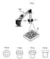
- an image of a pile of workpieces which are objects for detection having identical shapes and randomly arranged as shown in FIG. 1 is captured by the two dimensional visual sensor 21, and orientation, or orientation and position, of an operation to be performed by the robot RB is determined based on the captured image.
- rough position and posture of the individual workpieces are detected to determine the orientation of the robot based on the captured image and then precise position and posture of the workpiece are detected by the two-dimensional visual sensor 21 or a three-dimensional visual sensor 22.
- images of a reference object which is one of workpieces W subjected to a picking-up operation or an object having a shape identical to that of the workpiece W are captured in different directions by the image capturing device and reference models are created from the image data obtained by the image capturing and stored in advance.
- Matching processing between the image data obtained by capturing the image of the pile of workpieces and the reference models is executed to select an image of one workpiece matched with one of reference models, and the position/posture of the selected workpiece is determined based on the selected image of the workpiece in the image field of view, the selected one of reference modes and the position/posture information associated with the selected one of the reference models.
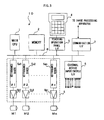
- FIG. 3 is a block diagram showing a principal part of a robot controller 10 for use in an embodiment of the present invention.
- a main processor 1 a memory 2 including a RAM, a ROM and a nonvolatile memory (such as an EEPROM), an interface 3 for a teaching operating panel, an interface 6 for external devices, an interface 7 for an image processing apparatus and a servo control section 5 are connected to a bus 8.
- a teaching operating panel 4 is connected to the interface 3.
- a system program for supporting basic functions of the robot RB and robot controller 10 are stored in the ROM of the memory 2.
- Robot operation programs and their related determined data which are taught in accordance with various operations are stored in the nonvolatile memory of the memory 2.
- the RAM of the memory 2 is used for temporary storage of data for various arithmetical operations performed by the processor 1.
- the servo control section 5 comprises servo controllers 5al to San (n: sum of the number of all the axes of the robot including additional movable axes of a tool attached to the wrist of the robot), each composed of a processor, a ROM, a RAM, etc.
- Each servo controller performs position/velocity loop control and also current loop control for its associated servomotor for driving the axis, to function as a so-called digital servo controller for performing loop control of position, velocity and current by software.
- Each servomotor M1-Mn for driving each axis is drivingly controlled according to outputs of the associated servo controller 5al-5an through the associated servo amplifier 5bl-5bn. Though not shown in FIG.
- a position/velocity detector is attached to each servomotor Ml-Mn, and the position and velocity of each servomotor detected by the associated position/velocity detector is fed back to the associated servo controller 5al-5an.
- To the input/output interface 6 are connected sensors of the robot, and actuators and sensors of peripheral devices.
- FIG 4 is a block diagram of the image processing apparatus 30 connected to an interface 7 of the robot controller 10.
- the image processing apparatus 30 comprises a processor 31 to which are connected through a bus 42 a ROM 32 for storing a system program to be executed by the processor 31, an image processor 33, a camera interface 34 connected to a CCD camera 21 which is a first visual sensor serving as a first image data capturing device, a three-dimensional sensor interface 35 connected to a three-dimensional sensor 22 as a second visual sensor as a second image data capturing device, a MDI 36 with a display such as a CRT or a liquid crystal display for inputting and outputting various commands and data, a frame memory 37, a nonvolatile memory 38, a RAM 39 for temporary storage of data, a communication interface 40 for the robot controller and a console interface 41 for a console 43.
- a processor 31 to which are connected through a bus 42 a ROM 32 for storing a system program to be executed by the processor 31, an image processor 33, a camera interface 34
- An image captured by the CCD camera 21 is converted into a light and shade grey scale image and stored in the frame memory 37.
- the image processor 33 performs image processing of images stored in the frame memory 37 on demand by the processor 31 so as to recognise an object.
- the architecture and function of the image processing apparatus 30 itself is in no way different from the conventional image processing apparatus.
- the image processing apparatus 30 of the present invention is different from the conventional one in that reference models as described later are stored in the nonvolatile memory 38 and pattern matching processing is performed on an image of a pile of workpieces W captured by the first visual sensor 21 using the reference models to obtain position and posture of a workpiece W and thus orientation, or orientation and position, of an operation to be performed by the robot RB.
- the image processing apparatus of the present invention differs from the conventional one in that approach orientation/position for more precise detection of the position/posture of the workpiece W by the second visual sensor of the three-dimensional visual sensor 22 is determined based on the detected position/posture of the workpiece W using the first visual sensor 21.
- the CCD camera for obtaining two-dimensional images data is well known in the art and thus detailed explanation thereof is omitted here.
- the three-dimensional visual sensor 22 for detecting a three-dimensional position of an object by irradiating structured light (slit beam) on the object is known and used in various fields. This type of sensor may be used as the three dimensional visual sensor 22. Further, a three-dimensional visual sensor of a spot-light scanning type as disclosed in Japanese Patent Publication No. 7-270137 may be used as the three-dimensional visual sensor 22, and the summary of such three-dimensional visual sensor is described below.
- This visual sensor detects a three-dimensional position of an object by irradiating a light beam to form a light spot on the object for scanning the object in two different directions (X direction and Y direction) and by detecting the light reflected on the object by a position sensitive detector (PSD).
- PSD position sensitive detector
- the scanning range (measuring range) on an object is set in advance, and an inclination angle ⁇ x, ⁇ y of the mirrors is controlled discretely. As shown in FIG. 7, the scanning is performed from a point (1,1) to a point (1, n), from a point (2,1) to a point (2, n), ..., from a point (m, 1) to a point (m, n) on the X-Y plane within the scanning range, to measure the three-dimensional positions of each reflected point on the object. Also, a distance Z (i, j) between the sensor and the reflection point (i, j) on the object is obtained and stored in the RAM38 of the image processing apparatus 30. Thus, the image data is obtained as two-dimensional arrangement data including the distance data Z (i, j) between the sensor and the reflection point on the object, as shown in FIG. 9.
- FIG. 10 is a flowchart of processing to be executed by the processor 31 of the image processing apparatus 30 for obtaining the image data.
- indexes i and j are respectively set to "1" (Step 300) and the inclination angle ( ⁇ x, ⁇ y) of the mirrors is set to (x1, yl) to direct to the start point (1, 1) and an irradiation command with the inclination angle is sent to the sensor 20 (Steps 301-303).
- the sensor irradiates a light beam with the mirrors set at the inclination angle.
- the signal representing the image captured by the PSD is sent to the image processing apparatus 30.
- the processor 31 of the image processing apparatus 30 calculates the position of the reflection point on the object from the signal from the PSD and the inclination angle ( ⁇ x, ⁇ y) of the mirrors to obtain the distance Z (i, j) between the sensor and the position of the reflection point on the object.
- This value Z (i, j) is stored in the RAM 38 as the two-dimensional arrangement data [i, j] (Step 304, 305).
- the calculation for obtaining the position of the reflection point and the distance Z (i, j) may be performed by the sensor 20.
- Step 306 the index i is incrementally increased by "1" and the inclination angle Dx of the mirror for X-axis direction scanning is increased by the predetermined amount Ax (Step 306, 307). It is determined whether or not the index i exceeds the set value n (Step 308). If the index i does not exceed the set value n, the procedure returns to Step 303 and the processing from Step 303 to Step 308 is executed to obtain the distance Z (i, j) of the next point. Subsequently, the processing of Steps 303-308 is repeatedly executed until the index i exceeds the set value n to obtain and store the distance Z (i, j) of the respective points (1, 1) to (1, n) shown in FIG. 8.
- Step 308 If it is determined that the index i exceeds the set value n in Step 308, the index i is set to "1" and the index j is incrementally increased by "l” to increase the inclination angle ⁇ y of the mirror for Y-axis direction scanning (Steps 309-311). Then, it is determined whether or not the index j exceeds the set value m (Step 312) and if the index j does not exceed the set value m, the procedure returns to Step 302 to repeatedly execute the processing of Step 302 and the subsequent Steps.
- Step 302 to Step 312 is repeatedly executed until the index j exceeds the set value m. If the index j exceeds the set value m, the points in the measurement range (scanning range) shown in FIG. 8 have been measured entirely, the distance data Z (1, 1) - Z (m, n) as two-dimensional arrangement data are stored in the RAM 39 and the image data obtaining processing is terminated. A part of the image data of two-dimensional arrangements or a plurality of distance data can be obtained by appropriately omitting the measurement of the distance for the index i.
- the foregoing is a description on the processing for obtaining two-dimensional arrangement data as image data using the visual sensor capable of measuring the distance.
- the two-dimensional arrangement data obtained in this way as image data, creation of reference models and detection of position and posture (orientation) of an object can be performed.
- FIG. 5 is a flowchart showing processing for teaching reference models to the image processing apparatus 30 according to the present invention.
- One reference workpiece (one of the workpieces W as objects of robot operation or a workpiece having a three-dimensional shape identical to that of the workpiece W) is arranged at a predetermined position with predetermined posture for creating reference models.
- a first (0-th) position and orientation (posture) of the CCD camera 21 for capturing the image of the object is set, and an axis of rotation and rotation angles with respect to the first (0-th) position and orientation (posture) are set in order to determine the subsequent positions and orientations (postures) of the camera 21 from the teaching operation panel 4 of the robot controller 10.
- the number of the positions and orientations (postures) of the workpiece at which the camera 21 captures the image of the object are set.
- images of the reference workpiece are captured from four different directions and reference models are created based on the four image data.
- an image of the reference workpiece is captured from the direction of a Z-axis of a world coordinate system at 0-th position/orientation (posture) to create 0-th reference model.
- 0-th position/orientation posture
- an axis perpendicular to an optical axis of the camera and passing a central point of the workpiece (an origin of a world coordinate system set to the workpiece) and rotation angles along the rotation axis are set.
- an axis parallel to either the X-axis or the Y-axis of the world coordinate system, which is perpendicular to the Z axis, can be selected and the workpiece is rotated around the rotation axis at the workpiece position.
- an axis parallel to the X-axis of the world coordinate system is set as the rotation axis, and for the position/posture shown in FIG. 2b, the rotation angle of 30° is set to rotate the camera by 30° with respect to the workpiece along the rotation axis.
- a first reference model is created based on the image data of the workpiece at the position/orientation (posture)shown in FIG. 2b.
- the camera 21 is rotated by 60° and 90°, respectively, along the rotation axis for capturing images of the workpiece to create second and third reference models. Only posture (orientation) information may be stored to be associated with each reference model in the case where the relative position between the camera and the reference workpiece is not changed, as in this example.
- rotation angles of zero degree, 30 degrees, 60 degrees and 90 degrees are set for creating four reference models.
- the dividing range of the rotation angles may be set more finely and/or range of the rotation angle may be set greater to create more reference models for more precise detection of the position/posture of the workpiece.
- the 0-th position/posture of the robot at which the camera 20 captures the image of the object, and the rotation axis and the rotation angles with respect to the 0-th position/posture are set in advance in order to determine the subsequent positions/postures of the reference workpiece, and also the number of the subsequent positions/postures of the workpiece are set.
- the optical axis of the camera is parallel to the Y-axis of the world coordinate system and that a position where the X-axis and Y-axis coordinate values are identical to those of the reference workpiece arranged at a predetermined position with a predetermined posture and only the Z-axis coordinate value is different form that of the position of the reference workpiece taught to the robot as the 0-th image capturing position for obtaining the 0-th reference model.
- the positions of the robot where the camera is rotated with respect to the reference workpiece by 30 degrees, 60 degrees and 90 degrees along the axis passing the central point of the reference workpiece and parallel to the X-axis of the world coordinate system are set as the 1st, 2nd and 3rd image capturing positions, and the number N of the image capturing positions is set "4."
- the processor 1 of the robot controller 10 sets a counter M for counting the number of the image capturing to "0" (Step 100).
- the robot is operated to have the M-th positionlposture and a command for image capturing is outputted to the image processing apparatus 30 (Step 101).
- the image processing apparatus 30 performs capturing of an image of the reference workpiece with the camera 20 and the captured image data is stored in the frame memory 37. Further, relative position/orientation (posture) of the workpiece with respect to the camera is obtained and stored in the nonvolatile memory 37 as relative position/orientation (posture) of M-th reference model (Step 103).
- first-sensor relative position/posture This relative position/posture is hereinafter referred to as "first-sensor relative position/posture”.
- position/posture of the workpiece in a camera coordinate system set to the camera is obtained from the position/posture of the camera and the position/posture of the reference workpiece in the world coordinate system when capturing the image by the camera, and is stored as the relative position/posture of the workpiece with respect to the camera (the first-sensor relative position/posture).
- the position/posture of the workpiece in the camera coordinate system is stored as [x0, y0, z0, ⁇ 0, ⁇ 0, ⁇ 0]c, where ⁇ , ⁇ and ⁇ mean rotation angle around X-, Y-, Z- axes, and "c" means the camera coordinate system.
- ⁇ , ⁇ and ⁇ mean rotation angle around X-, Y-, Z- axes
- c means the camera coordinate system.
- only the orientation(posture) of the camera [x0, y0, z0, ⁇ 0, ⁇ 0, ⁇ 0]c is stored to be associated with each reference model as the relative position/posture of the first sensor.
- the relative position/posture of (the tool center point of) the robot to be situated with respect to the workpiece, or the relative position/posture of the second visual sensor 22 to be situated with respect to the workpiece is stored to be associated with M-th reference model, for a subsequent operation performed by the robot, i.e., a precise detection of position/posture of the workpiece by the second visual sensor 22.
- This relative position/posture is hereinafter referred to as "workpiece-robot (second sensor) relative position/posture”.
- a data-captured signal is sent to the robot controller 10 (Step 104).
- the workpiece-robot (second sensor) relative position/posture is for determining orientation and/or position of a subsequent operation of the robot RB, i.e., the orientation/position of the robot at which the three-dimensional sensor 22 can detect the object or a characteristic portion of the object, more precisely.
- the workpiece-robot relative position/posture may be set to the relative position/posture between the tool center point and the workpiece which is most suitable for picking up the workpiece by a robot hand.
- the workpiece-robot (second sensor) relative position/posture is stored as position/posture of the tool center point or the three-dimensional visual sensor 22 in a workpiece coordinate system set to the workpiece.
- the following explanation is given assuming that the relative position/posture of the three-dimensional visual sensor 22 is stored.
- the workpiece-robot (second sensor) relative position/posture is represented by an approach vector for determining approach position/posture of the three-dimensional visual sensor 22 with respect to the workpiece in precise measuring position/posture of the workpiece W by the three-dimensional visual sensor 22.
- One approach vector may be commonly set to reference models created for one kind of reference workpiece, since the optimal position/posture of the tool center point with respect to the workpiece can be determined unequivocally in accordance with a kind of the workpiece for precisely measuring the position/posture of the workpiece by the three-dimensional visual sensor 22 or picking up the workpiece by the robot hand.
- the approach vector may be selected from a plurality of patterns prepared in advance and may include orientation (posture) information only.
- the workpiece-robot (second sensor) relative position/posture can be expressed by three components (X, Y, Z)wp for parallel motion and three components ( ⁇ , ⁇ , ⁇ )wp for rotation, where wp means the workpiece coordinate system.
- the workpiece-robot (second sensor) relative position/posture is commonly set for all the reference models.
- the information to be stored in Steps 103 and 104 may be gathered as the relative position/posture of the second visual sensor to be situated with respect to the CCD camera 21.
- the reference models are stored in the nonvolatile memory 38 and also the first-sensor relative position/posture, which is the relative position/posture of the first visual sensor 21 and the workpiece W and the workpiece-robot (second sensor) relative position/posture, which is the position/posture of the second visual sensor 22 (or the robot) to be situated with respect to the workpiece W are stored in the nonvolatile memory 38.
- the reference models may be created from a part of the image data of the reference object, and may be created by processing the image data of the reference object.
- FIG. 7 shows an example of the first-sensor relative position/posture and the workpiece-robot (second sensor) relative position/posture in the case of four reference models.
- the first-sensor relative position/posture is expressed as position/posture of the workpiece W in the camera coordinate system (X, Y, Z, ⁇ , ⁇ , ⁇ )c set for the CCD camera 21.
- the CCD camera is rotated around the axis parallel to the X-axis of the world coordinate system with a center of rotation set to the origin of the workpiece coordinate system, and since the X-axis of the camera coordinate system is set parallel to the X-axis of the world coordinate system, only the rotation angles a in the camera coordinate system are changed.
- the workpiece-robot (second sensor) relative position/posture is expressed as the position/posture of the second visual sensor 22 in the workpiece coordinate system (X, Y, Z, ⁇ , ⁇ , ⁇ )wp set to the workpiece, and the approach vector (30.5, 20.5, 60.9, 0.0, 0.0, 0.0)wp is set to represent constant orientation with respect to the workpiece W.
- the reference models and the relative position/posture of the workpiece W and the camera 20 are stored in the nonvolatile memory 38 of the image processing apparatus 30.
- the reference models are created using a robot, although the reference models may be created by a manual operation without using a robot.
- the reference workpiece is arranged within a field of view of the camera connected to the image processing apparatus 30, and the images of the workpiece with different postures are captured by the camera.
- the reference models are created based on the image data and the relative positions/postures of the camera and the workpiece at the image capturing are manually inputted, and are stored with the respective relative positions/postures.
- FIG. 6 is a flowchart of processing for the picking-up operation using the reference models.
- the processor 1 When a picking-up command is inputted into the robot controller 10 from the teaching operation panel 4, the processor 1 operates the robot RB to move the camera attached to the robot wrist to an image capturing position where a pile of workpieces are within a field of view of the CCD camera 21 (Step 200). Three-dimensional position/posture of the camera 21 on the world coordinate system at this image capturing position is outputted to the image processing apparatus 30, and an image capturing command is outputted (Step 201). Upon receipt of the image capturing,command, the processor 31 of the image processing apparatus 30 captures an image of the pile of the workpieces W to obtain image data of some workpieces W and store the data in the frame memory 37 (Step 202).
- pattern matching processing is performed for the image data stored in the frame memory 37 using one of the reference models (first reference model) stored in the nonvolatile memory 37 so as to detect a workpiece W (Step 203).
- this pattern matching processing matching of the image data of the reference model with the image data of workpieces is performed on the basis of position, turn and scale.
- Step 204 If it is determined in Step 204 that an object having a matching value equal or greater than the set value with respect to any of the reference models is detected, the procedure proceeds to Step 207 to perform matching processing on the two-dimensional data of the detected workpieces W. using every taught mode.
- Step 208 the reference model having the largest matching value in the pattern matching processing is selected, and the relative position/posture of the workpiece W with respect to the camera 21 is determined based on the first-sensor relative position/posture, i.e., the relative position/posture of the camera and the reference workpiece stored for the selected reference model, and position, rotation angle and scale of the image of the workpiece in the matching processing as well as data of the workpiece-robot (second sensor) relative position/posture associated with the selected reference model, which represent the position/posture of the second sensor 22 to be situated with respect to the workpiece are read from the nonvolatile memory 37 (Step 208).
- the first-sensor relative position/posture i.e., the relative position/posture of the camera and the reference workpiece stored for the selected reference model
- position, rotation angle and scale of the image of the workpiece in the matching processing as well as data of the workpiece-robot (second sensor) relative position/posture associated with the selected reference model, which represent the position/posture of the second
- the reference model having the highest matching value is selected in this embodiment, although a reference model of the rotation angle of zero degree (the O-th reference model) may be selected with precedence, or an object having the highest expansion rate of scale (the object which is nearest to the camera, i.e. located at the top of the pile in this example) may be selected with precedence.
- the position and posture (orientation) of the detected workpiece on the world coordinate system is determined from the position and posture of the camera 21 in the world coordinate system, which has been sent in Step 201, and the relative position/posture of the workpiece W with respect to the camera 21, and is outputted (Step 209).
- the position and posture (orientation) of the detected workpiece W in the world coordinate system is obtained by an arithmetical operation of coordinate transformation using the data of the position/posture of the workpiece W in the camera coordinate system and the position/posture of the camera 20 in the world coordinate system (Step 209).
- the position/posture of the second visual sensor 22 to be situated for a subsequent operation in the world coordinate system is determined based on the determined position/posture of the detected workpiece W in the world coordinate system and the workpiece-robot (second sensor) relative position/posture data (approach vector) (Step 210).
- the processor 1 operates the robot to situate the second visual sensor 22 to have the determined position/posture, and outputs a measuring command to the second visual sensor 22 (Step 211).
- the three-dimensional sensor 22 Upon receipt of the measuring command, the three-dimensional sensor 22 measures a three-dimensional position/posture of the workpiece W. Since the second visual sensor 22 is situated at a suitable position/posture with respect to the workpiece W designated by the approach vector, the three-dimensional position/posture of the workpiece W can be precisely measured.
- the processor 31 of the image processing apparatus 30 outputs the result of measurement to the robot controller 10 (Step 212).
- the robot controller 10 operates the robot to perform a picking-up operation to grip and hold the detected workpiece W and move the held workpiece W to a predetermined position, based on the result of measurement by the three-dimensional visual sensor 22 (Step 213). Then, the procedure returns to Step 202 to repeatedly execute the processing of Step 202 and subsequent Steps.
- the procedure may return to Step 200 when it is determined "Yes" in Step 205, to move the camera to another position/posture at which an image of the objective workpiece can be captured.
- the three-dimensional sensor 22 is adopted as the second visual sensor for precisely detecting the position/posture of the workpiece, although the two-dimensional sensor may be adopted instead of the three-dimensional sensor.
- the second sensor may be provided in addition to the first visual sensor, or the first visual sensor may function as the second visual sensor.
- the position/posture of the individual workpiece in the pile of workpieces is roughly detected by the first visual sensor and the precise position/posture of the detected workpiece is detected by the second visual sensor situated at the suitable position/posture which is nearer to the workpiece W, to improve the precision of detection. Therefore, when the first visual sensor takes place of the second visual sensor, precise position/posture of the workpiece can be detected by capturing the image of the detected workpiece W from the shorter distance and performing the matching processing by the CCD camera as the second sensor.
- the camera may be moved in parallel in accordance with the position of the workpiece in the field of view of the camera to a position right above the workpiece to lose the influence of parallax, and at this position the image capturing processing of Step 201 and the subsequent Steps in FIG. 6 is performed so that false judgment is prevented.
- the first visual sensor is mounted on the distal end of the robot wrist, although the first visual sensor may be a stationary camera fixed at a place above the pile of the workpieces.
- the distance between the camera and the workpieces is lengthened to prevent the influence of parallax. Also, it is not necessary to operate the robot to capture the image of the workpieces by the first visual sensor to shorten the cycle time.
- one kind of object (workpieces) are detected and picked up, although, the robot system can be modified to detect and pick up plural kinds of objects (workpieces).
- Ma is the number of reference models created from a reference workpiece of a kind A
- Mb is the number of reference models created from a reference workpiece of a kind B and information of the workpiece kinds A or B are additionally stored to be associated with each reference model. Then, matching processing is carried out between the captured image and the (Ma+Mb) number of reference models to select the matched reference model, and the workpiece kind information, in addition to the orientation and/or position for the subsequent operation, are determined. In this way, it is not necessary to separate the workpieces according to the kind of workpieces in advance, so that the mixed kinds of workpiece can be picked up one by one to reduce the operational cost.
- the position/posture of the object is roughly determined based on image data captured by the first visual sensor and the precise position/posture of the detected workpiece is measured by the second visual sensor, although, the second image capturing device may be omitted and the orientation and/or position of the robot operation can be determined using the first image data capturing device only.
- the relative position/posture of the robot (tool center point) to be situated with respect to the workpiece is stored as the workpiece-robot relative position/posture.
- a position/posture of an objective workpiece in a randomly arranged pile of workpieces of one kind or a plurality of kinds, or an aggregation of workpieces of one kind or a plurality of kinds gathered in a predetermined region, which have different three-dimensional positions/postures, is-detected, and an orientation/position for an operation on the detected workpiece by a robot is determined.
- the second image data capturing device measures the position/posture of the workpiece more precisely at the determined position/posture (approach vector) for the robot operation. Therefore, the robot can securely perform a picking-up operation of picking up an individual workpiece from such a pile or an aggregation.
Landscapes
- Engineering & Computer Science (AREA)
- Robotics (AREA)
- Mechanical Engineering (AREA)
- Manipulator (AREA)
- Image Processing (AREA)
- Image Analysis (AREA)
- Numerical Control (AREA)
Abstract
Description
Claims (12)
- A robot system having an image processing function for determining posture, or posture and position of a robot operation on an object comprising:a robot;a first image capturing device;a memory storing reference model created according to image data of a reference object captured by said image capturing device in a plurality of different directions, and storing information of the capturing directions to be respectively associated with said reference models, and information of orientation of the robot operation with respect to the object, said reference object being the object for detection or an object having a shape identical to that of the object for detection; anda processor to perform matching processing on image data containing an image of the object for detection captured by said image capturing device with said reference models to select an image of an object matched with one of said reference models, and to determine orientation, or orientation and position, of an operation to be performed by the robot based on the selected image of the object, said one reference model and the information about the capturing direction and information about the orientation of the robot operation with respect to the object associated with said one reference model.
- A robot system having an image processing function for determining posture, or posture and position of a robot operation on an object comprising:a robot;a first image capturing device;a memory storing reference model created according to image data of different kinds of reference objects captured by said first image capturing device, and storing information of the kinds respectively associated with said reference models, and information about orientation of the robot operation with respect to the object of each kind, each of said reference objects being an object of operation of one such kind or an object having a shape identical to that of the object of operation of one such kind; anda processor to perform matching processing on image data containing an image of the object for operation captured by said first image capturing device with said reference models to select an image of an object matched with one of said reference models, and to determine orientation, or orientation and position of the robot operation based on the selected image of the object, said one reference model, the information about the kind of information associated with said one reference model and the information of the orientation about the robot operation respect to the object associated with said one reference model.
- A robot system having an image processing function according to claim 1 or 2, wherein said reference models are obtained from a part of the image data of the reference object.
- A robot system having an image processing function according to claim 1 or 2, wherein said reference models are obtained by processing the image data of the reference object.
- A robot system having an image processing function according to any preceding claim, wherein said first image capturing device comprises a camera for capturing two-dimensional image data.
- A robot system having an image processing function according to claim 5, wherein said image data of the reference object are captured by said camera from a predetermined distance.
- A robot system having an image processing function according to any preceding claim, wherein said robot system further comprises a second image capturing device andsaid robot situates said second image data capturing device to have said determined orientation or to have said determined orientation and said determined position with respect to the object, andsaid processor processes second image data captured by said second image capturing device to detect position and/or posture of the object with respect to said second image data capturing device
- A robot system having an image processing function according to any one of claims 1 to 6, wherein said robot system further comprises a second image capturing device for obtaining three-dimensional position;said robot situates said second image data capturing device to have said determined orientation or to have said determined orientation and said determined position with respect to the object, so that said second image data capturing device is directed to a characterising portion of the object; andsaid processor detects three-dimensional position and/or posture of the object based on three-dimensional position of said characterising portion obtained by said second image capturing device.
- A robot system having an image processing function according to claim 7 or 8, wherein said first image data capturing device is used as said second image data capturing device.
- A robot system having an image processing function according to claim 7, 8 or 9, wherein said second image capturing device comprises a three-dimensional visual sensor of spot-light scanning type capable of measuring distance between the sensor and an object.
- A robot system having an image processing function according to claim 7, 8 or 9, wherein said second image data capturing device comprises a structured-light unit for irradiating a structured light on an object and capturing an image of the object including the irradiated light on the object.
- A robot system having an image processing function according to any preceding claim, wherein said, robot operation is an operation for picking up at least one object from a plurality of objects overlapped with each other.
Applications Claiming Priority (2)
| Application Number | Priority Date | Filing Date | Title |
|---|---|---|---|
| JP10189199 | 1999-04-08 | ||
| JP10189199A JP3300682B2 (en) | 1999-04-08 | 1999-04-08 | Robot device with image processing function |
Publications (3)
| Publication Number | Publication Date |
|---|---|
| EP1043642A2 true EP1043642A2 (en) | 2000-10-11 |
| EP1043642A3 EP1043642A3 (en) | 2005-08-31 |
| EP1043642B1 EP1043642B1 (en) | 2008-09-03 |
Family
ID=14312561
Family Applications (1)
| Application Number | Title | Priority Date | Filing Date |
|---|---|---|---|
| EP00303008A Expired - Lifetime EP1043642B1 (en) | 1999-04-08 | 2000-04-10 | Robot system having image processing function |
Country Status (4)
| Country | Link |
|---|---|
| US (1) | US7177459B1 (en) |
| EP (1) | EP1043642B1 (en) |
| JP (1) | JP3300682B2 (en) |
| DE (1) | DE60040110D1 (en) |
Cited By (44)
| Publication number | Priority date | Publication date | Assignee | Title |
|---|---|---|---|---|
| WO2004000508A1 (en) * | 2002-06-24 | 2003-12-31 | Matsushita Electric Industrial Co., Ltd. | Articulated driving mechanism, method of manufacturing the mechanism, and holding hand and robot using the mechanism |
| EP1428634A2 (en) | 2002-12-13 | 2004-06-16 | Fanuc Ltd | Workpiece taking-out robot with a three-dimensional visual sensor |
| EP1391275A3 (en) * | 2002-08-23 | 2004-06-16 | Fanuc Ltd | Object handling apparatus |
| WO2004052596A1 (en) * | 2002-12-10 | 2004-06-24 | Svensk Industriautomation Ab | Method and arrangement to avoid collision between a robot and its surroundings while picking details including a sensorsystem |
| EP1480169A1 (en) * | 2003-05-20 | 2004-11-24 | Fanuc Ltd | Image processing apparatus |
| FR2896441A1 (en) * | 2006-01-23 | 2007-07-27 | Jerome Grosbois | METHOD AND SYSTEM FOR AUTOMATED REALIZATION OF WORKPIECE (S) |
| EP1816604A2 (en) | 2006-02-01 | 2007-08-08 | Fanuc Ltd | Workpiece picking device |
| WO2008101568A1 (en) * | 2007-02-23 | 2008-08-28 | Abb Technology Ag | Device for controlling a robot |
| WO2008107769A3 (en) * | 2007-03-08 | 2008-11-06 | Smv S R L | A method and a device for recognising, collecting and repositioning objects |
| DE102007060653A1 (en) * | 2007-12-15 | 2009-06-18 | Abb Ag | Position determination of an object |
| GB2461959A (en) * | 2008-07-22 | 2010-01-27 | Recognition Robotics Inc | A visual guidance and work piece recognition system for a manipulator |
| US7957583B2 (en) | 2007-08-02 | 2011-06-07 | Roboticvisiontech Llc | System and method of three-dimensional pose estimation |
| WO2011031523A3 (en) * | 2009-08-27 | 2011-07-07 | Abb Research Ltd. | Robotic picking of parts from a parts holding bin |
| US8095237B2 (en) | 2002-01-31 | 2012-01-10 | Roboticvisiontech Llc | Method and apparatus for single image 3D vision guided robotics |
| US8144193B2 (en) | 2009-02-09 | 2012-03-27 | Recognition Robotics, Inc. | Work piece tracking system and method |
| US8150165B2 (en) | 2008-04-11 | 2012-04-03 | Recognition Robotics, Inc. | System and method for visual recognition |
| EP2263837A4 (en) * | 2008-03-10 | 2012-08-29 | Toyota Motor Co Ltd | OPERATING GUIDANCE SYSTEM AND OPERATING METHOD |
| CN102656419A (en) * | 2009-11-20 | 2012-09-05 | 微-埃普西龙测量技术有限两合公司 | Robot for automatic 3-D measurement and method |
| ITTO20110214A1 (en) * | 2011-03-10 | 2012-09-11 | Febo S R L | METHOD AND TRANSFER SYSTEM FOR PLACING A PIECE IN A REQUESTED ORIENTATION, AND ROBOT CLAMP FOR SUCH TRANSFER SYSTEM |
| NL2006950C2 (en) * | 2011-06-16 | 2012-12-18 | Kampri Support B V | Cleaning of crockery. |
| US8437535B2 (en) | 2006-09-19 | 2013-05-07 | Roboticvisiontech Llc | System and method of determining object pose |
| EP2468451A3 (en) * | 2007-04-26 | 2013-09-04 | Adept Technology Inc. | Vacuum gripping apparatus |
| US8559699B2 (en) | 2008-10-10 | 2013-10-15 | Roboticvisiontech Llc | Methods and apparatus to facilitate operations in image based systems |
| CN103402715A (en) * | 2010-12-30 | 2013-11-20 | 泽恩机器人技术有限公司 | Method, computer program and apparatus for determining a gripping location |
| CN103489200A (en) * | 2012-06-11 | 2014-01-01 | 佳能株式会社 | Image processing apparatus and image processing method |
| CN104227723A (en) * | 2013-06-07 | 2014-12-24 | 株式会社安川电机 | Workpiece detector, robot system, method for producing to-be-processed material, method for detecting workpiece |
| US8954182B2 (en) | 2010-08-31 | 2015-02-10 | Kabushiki Kaisha Yaskawa Denki | Robot system |
| EP2789431A3 (en) * | 2013-04-08 | 2015-04-15 | Omron Corporation | Control system and control method |
| EP2957397A3 (en) * | 2014-06-20 | 2016-01-20 | Ricoh Company, Ltd. | Measurement system, object pickup system, measurement method, and carrier means |
| CN106041930A (en) * | 2016-06-27 | 2016-10-26 | 长沙长泰机器人有限公司 | Machining system with workpiece position compensation function and control method |
| US9576217B2 (en) | 2008-04-11 | 2017-02-21 | Recognition Robotics | System and method for visual recognition |
| CN108748136A (en) * | 2018-04-10 | 2018-11-06 | 上海新时达机器人有限公司 | Robot stacking program creating method, storage medium and teaching machine |
| CN109375573A (en) * | 2018-11-22 | 2019-02-22 | 南通科技职业学院 | A kind of image processing method of industrial machine vision system |
| US10310472B2 (en) | 2014-10-23 | 2019-06-04 | Comau S.P.A. | System for monitoring and controlling an industrial plant |
| US10434649B2 (en) | 2017-02-21 | 2019-10-08 | Fanuc Corporation | Workpiece pick up system |
| CN110480683A (en) * | 2019-08-28 | 2019-11-22 | 哈尔滨工业大学 | A large-scale tool software system designed for the integrated design of robot application system solutions |
| WO2019212860A3 (en) * | 2018-05-02 | 2020-02-20 | X Development Llc | Positioning a robot sensor for object classification |
| CN110977921A (en) * | 2019-10-17 | 2020-04-10 | 上海飒智智能科技有限公司 | An intelligent mobile collaborative robot |
| CN111515943A (en) * | 2019-02-01 | 2020-08-11 | 发那科株式会社 | Three-dimensional shape measurement system and three-dimensional shape measurement method |
| CN111745640A (en) * | 2019-03-28 | 2020-10-09 | 精工爱普生株式会社 | Object detection method, object detection device, and robot system |
| US10877452B2 (en) | 2018-05-04 | 2020-12-29 | Comau S.P.A. | Method of monitoring the operating state of a processing station, corresponding monitoring system and computer program product |
| EP3711909A3 (en) * | 2019-03-22 | 2021-01-06 | Günther Battenberg | Method for performing at least one activity process using a robot |
| CN116137062A (en) * | 2021-11-18 | 2023-05-19 | 精工爱普生株式会社 | Method, system and storage medium for generating training data |
| DE102023122703A1 (en) * | 2023-08-24 | 2025-02-27 | MTU Aero Engines AG | measurement on a component |
Families Citing this family (89)
| Publication number | Priority date | Publication date | Assignee | Title |
|---|---|---|---|---|
| JP3421608B2 (en) | 1999-04-08 | 2003-06-30 | ファナック株式会社 | Teaching model generator |
| JP2002133413A (en) * | 2000-10-26 | 2002-05-10 | Kawasaki Heavy Ind Ltd | Method and apparatus for identifying a three-dimensional object using image processing |
| JP4255050B2 (en) * | 2002-08-28 | 2009-04-15 | 株式会社キーエンス | Image processing device |
| JP4004899B2 (en) | 2002-09-02 | 2007-11-07 | ファナック株式会社 | Article position / orientation detection apparatus and article removal apparatus |
| JP3834297B2 (en) * | 2003-05-12 | 2006-10-18 | ファナック株式会社 | Image processing device |
| JP2005078375A (en) * | 2003-08-29 | 2005-03-24 | Sony Corp | Direction recognition apparatus, direction recognition method, direction recognition system, and robot apparatus |
| JP2005111619A (en) * | 2003-10-08 | 2005-04-28 | Tsubakimoto Chain Co | Method and apparatus for arranging article |
| DE10361018C9 (en) * | 2003-12-23 | 2021-03-04 | QUISS Qualitäts-Inspektionssysteme und Service GmbH | Method for recognizing a structure to be applied to a substrate with a plurality of cameras and a device therefor |
| EP1571584A1 (en) * | 2004-03-03 | 2005-09-07 | Honda Research Institute Europe GmbH | Integrating visual and object information in a pervasive computing environment |
| FR2872728B1 (en) * | 2004-07-06 | 2006-09-15 | Commissariat Energie Atomique | METHOD FOR SEIZING AN OBJECT BY A ROBOT ARM PROVIDED WITH A CAMERA |
| CN101890720B (en) * | 2004-07-13 | 2012-01-11 | 松下电器产业株式会社 | Article holding system, robot, and method of controlling robot |
| SE529377C2 (en) * | 2005-10-18 | 2007-07-24 | Morphic Technologies Ab Publ | Method and arrangement for locating and picking up items from a carrier |
| JP4715539B2 (en) * | 2006-02-15 | 2011-07-06 | トヨタ自動車株式会社 | Image processing apparatus, method thereof, and image processing program |
| US7970177B2 (en) * | 2006-03-23 | 2011-06-28 | Tyzx, Inc. | Enhancing stereo depth measurements with projected texture |
| US20070276539A1 (en) * | 2006-05-25 | 2007-11-29 | Babak Habibi | System and method of robotically engaging an object |
| JP5403861B2 (en) * | 2006-11-06 | 2014-01-29 | キヤノン株式会社 | Information processing apparatus and information processing method |
| WO2008076942A1 (en) * | 2006-12-15 | 2008-06-26 | Braintech Canada, Inc. | System and method of identifying objects |
| EP2417499A1 (en) | 2009-04-11 | 2012-02-15 | Abb Ag | Robot system |
| US20120053728A1 (en) * | 2009-04-23 | 2012-03-01 | Koninklijke Philips Electronics N.V. | Object-learning robot and method |
| JP5427523B2 (en) * | 2009-09-08 | 2014-02-26 | 本田技研工業株式会社 | Visual equipment |
| US8941726B2 (en) * | 2009-12-10 | 2015-01-27 | Mitsubishi Electric Research Laboratories, Inc. | Method and system for segmenting moving objects from images using foreground extraction |
| KR101079702B1 (en) * | 2010-02-18 | 2011-11-04 | 한국과학기술연구원 | Scan Data Matching System and Scan Data Matching Method using the same |
| JP5525953B2 (en) * | 2010-07-29 | 2014-06-18 | 株式会社キーエンス | Dimension measuring apparatus, dimension measuring method and program for dimension measuring apparatus |
| JP5685027B2 (en) * | 2010-09-07 | 2015-03-18 | キヤノン株式会社 | Information processing apparatus, object gripping system, robot system, information processing method, object gripping method, and program |
| JP5630208B2 (en) * | 2010-10-25 | 2014-11-26 | 株式会社安川電機 | Shape measuring device, robot system, and shape measuring method |
| JP5767464B2 (en) * | 2010-12-15 | 2015-08-19 | キヤノン株式会社 | Information processing apparatus, information processing apparatus control method, and program |
| JP5675393B2 (en) * | 2011-01-31 | 2015-02-25 | 武蔵エンジニアリング株式会社 | Operation program automatic generation program and apparatus |
| JP5533727B2 (en) * | 2011-02-18 | 2014-06-25 | 株式会社安川電機 | Work picking system |
| JP5824939B2 (en) * | 2011-07-27 | 2015-12-02 | 株式会社Ihi | Method and apparatus for aligning plate workpieces |
| JP5852364B2 (en) * | 2011-08-26 | 2016-02-03 | キヤノン株式会社 | Information processing apparatus, information processing apparatus control method, and program |
| JP5854815B2 (en) * | 2011-12-20 | 2016-02-09 | キヤノン株式会社 | Information processing apparatus, information processing apparatus control method, and program |
| JP5383836B2 (en) * | 2012-02-03 | 2014-01-08 | ファナック株式会社 | An image processing apparatus having a function of automatically adjusting a search window |
| EP2631201B1 (en) * | 2012-02-22 | 2014-06-18 | CareFusion Germany 326 GmbH | Method for determining when medicine packages are positioned incorrectly |
| JP5975685B2 (en) * | 2012-03-09 | 2016-08-23 | キヤノン株式会社 | Information processing apparatus and information processing method |
| JP5977544B2 (en) | 2012-03-09 | 2016-08-24 | キヤノン株式会社 | Information processing apparatus and information processing method |
| JP6000579B2 (en) * | 2012-03-09 | 2016-09-28 | キヤノン株式会社 | Information processing apparatus and information processing method |
| US8996167B2 (en) * | 2012-06-21 | 2015-03-31 | Rethink Robotics, Inc. | User interfaces for robot training |
| JP5642738B2 (en) * | 2012-07-26 | 2014-12-17 | ファナック株式会社 | Apparatus and method for picking up loosely stacked articles by robot |
| JP5469216B2 (en) * | 2012-07-31 | 2014-04-16 | ファナック株式会社 | A device for picking up bulk items by robot |
| JP6021533B2 (en) | 2012-09-03 | 2016-11-09 | キヤノン株式会社 | Information processing system, apparatus, method, and program |
| JP5620445B2 (en) * | 2012-09-13 | 2014-11-05 | ファナック株式会社 | Article takeout device for determining holding position and posture of robot based on selection condition |
| KR102056664B1 (en) * | 2012-10-04 | 2019-12-17 | 한국전자통신연구원 | Method for work using the sensor and system for performing thereof |
| US9361695B2 (en) | 2012-12-11 | 2016-06-07 | Honda Motor Co., Ltd. | Method of recognizing a position of a workpiece from a photographed image |
| JP5616478B1 (en) | 2013-04-18 | 2014-10-29 | ファナック株式会社 | Robot system equipped with a robot for transporting workpieces |
| JP6188440B2 (en) | 2013-06-17 | 2017-08-30 | キヤノン株式会社 | Robot apparatus and robot control method |
| US10203683B2 (en) | 2013-07-16 | 2019-02-12 | Seagate Technology Llc | Coordinating end effector and vision controls |
| JP6245880B2 (en) * | 2013-07-31 | 2017-12-13 | キヤノン株式会社 | Information processing apparatus, information processing method, and program |
| JP6429450B2 (en) * | 2013-10-31 | 2018-11-28 | キヤノン株式会社 | Information processing apparatus and information processing method |
| JP5897532B2 (en) * | 2013-11-05 | 2016-03-30 | ファナック株式会社 | Apparatus and method for picking up articles placed in three-dimensional space by robot |
| US9259844B2 (en) | 2014-02-12 | 2016-02-16 | General Electric Company | Vision-guided electromagnetic robotic system |
| JP6380828B2 (en) * | 2014-03-07 | 2018-08-29 | セイコーエプソン株式会社 | Robot, robot system, control device, and control method |
| JP2015202544A (en) | 2014-04-15 | 2015-11-16 | 株式会社安川電機 | Robot control system, information communication module, robot controller, computer program, and robot control method |
| JP5778311B1 (en) * | 2014-05-08 | 2015-09-16 | 東芝機械株式会社 | Picking apparatus and picking method |
| JP6042860B2 (en) * | 2014-12-02 | 2016-12-14 | ファナック株式会社 | Article transferring apparatus and article transferring method for transferring article using robot |
| CH710648A1 (en) * | 2015-01-23 | 2016-07-29 | Erowa Ag | Measuring machine for measuring workpieces. |
| US10335951B2 (en) | 2015-07-29 | 2019-07-02 | Canon Kabushiki Kaisha | Information processing apparatus, information processing method, robot control apparatus, and robot system |
| US9418421B1 (en) * | 2015-09-26 | 2016-08-16 | Nastaran Neishaboori | Automation of biopsy specimen handling |
| JP6744709B2 (en) * | 2015-11-30 | 2020-08-19 | キヤノン株式会社 | Information processing device and information processing method |
| US9487357B1 (en) * | 2015-12-04 | 2016-11-08 | Genco | Method and apparatus for picking products |
| JP6088679B1 (en) * | 2016-02-19 | 2017-03-01 | ファナック株式会社 | Failure diagnosis device for robot system that determines failure from camera image |
| US9990685B2 (en) * | 2016-03-21 | 2018-06-05 | Recognition Robotics, Inc. | Automated guidance system and method for a coordinated movement machine |
| JP2017196705A (en) * | 2016-04-28 | 2017-11-02 | セイコーエプソン株式会社 | Robot and robot system |
| CN109791614B (en) * | 2016-07-15 | 2023-08-18 | 麦格纳国际公司 | System and method for adaptive case picking for manufacturing |
| JP2018034242A (en) * | 2016-08-31 | 2018-03-08 | セイコーエプソン株式会社 | Robot control device, robot, and robot system |
| JP6450727B2 (en) * | 2016-10-28 | 2019-01-09 | ファナック株式会社 | Apparatus, method, program, and recording medium for simulating article alignment work performed by robot |
| JP6915288B2 (en) * | 2017-02-08 | 2021-08-04 | オムロン株式会社 | Image processing system, image processing device, circuit reconstruction method in FPGA (Field Programmable Gate Array), and circuit reconstruction program in FPGA |
| JP6889574B2 (en) * | 2017-03-03 | 2021-06-18 | 株式会社キーエンス | Robot setting device, robot setting method, robot setting program, computer-readable recording medium, and recording equipment |
| JP6857052B2 (en) * | 2017-03-03 | 2021-04-14 | 株式会社キーエンス | Robot setting device, robot setting method, robot setting program, computer-readable recording medium, and recording equipment |
| JP2018167334A (en) * | 2017-03-29 | 2018-11-01 | セイコーエプソン株式会社 | Teaching device and teaching method |
| JP2019063984A (en) | 2017-10-02 | 2019-04-25 | キヤノン株式会社 | INFORMATION PROCESSING APPARATUS, METHOD, AND ROBOT SYSTEM |
| US11358290B2 (en) * | 2017-10-19 | 2022-06-14 | Canon Kabushiki Kaisha | Control apparatus, robot system, method for operating control apparatus, and storage medium |
| CN109202802B (en) * | 2018-11-14 | 2020-10-16 | 山东大学 | Visual guide system and method for clamping assembly |
| JP7204504B2 (en) * | 2019-01-29 | 2023-01-16 | 株式会社Subaru | Object confirmation device |
| JP2020196059A (en) * | 2019-05-31 | 2020-12-10 | セイコーエプソン株式会社 | robot |
| JP7328017B2 (en) * | 2019-06-11 | 2023-08-16 | ファナック株式会社 | Robot system and controller |
| JP7163506B2 (en) * | 2019-09-18 | 2022-10-31 | 株式会社Fuji | Work robots and work systems |
| EP4039618A4 (en) | 2019-09-30 | 2022-11-23 | Hai Robotics Co., Ltd. | CARGO PICKUP AND PLACEMENT CONTROL METHOD, DEVICE, HANDLING DEVICE AND HANDLING ROBOT |
| CN111496795B (en) * | 2020-04-29 | 2022-05-24 | 福建通力达实业有限公司 | Method and device for grabbing multilayer materials |
| KR20240130076A (en) * | 2021-12-27 | 2024-08-28 | 가부시키가이샤 니콘 | Control device, control system, robot system, control method and computer program |
| CN114578730A (en) * | 2022-02-22 | 2022-06-03 | 武汉珞珈天铭电气科技有限公司 | Control circuit of wire repairing robot |
| CN114952809B (en) * | 2022-06-24 | 2023-08-01 | 中国科学院宁波材料技术与工程研究所 | Workpiece recognition and pose detection method, system, and grasping control method of a robotic arm |
| CN115159149B (en) * | 2022-07-28 | 2024-05-24 | 深圳市罗宾汉智能装备有限公司 | Visual positioning-based material taking and unloading method and device |
| CN115533618B (en) * | 2022-09-26 | 2024-10-29 | 浙江力扬威亚智能装备有限公司 | Workpiece visual self-checking correction processing line |
| CN115497087B (en) * | 2022-11-18 | 2024-04-19 | 广州煌牌自动设备有限公司 | Tableware gesture recognition system and method |
| CN219009183U (en) * | 2022-11-30 | 2023-05-12 | 宁德时代新能源科技股份有限公司 | Pick-up tool |
| WO2024189792A1 (en) * | 2023-03-14 | 2024-09-19 | ファナック株式会社 | Device and method for generating search model, device and method for teaching operation position, and control apparatus |
| CN118163119B (en) * | 2024-05-16 | 2024-11-22 | 北京上成智饮机器人有限责任公司 | Intelligent control system and method of industrial robots based on cloud platform |
| CN119304878B (en) * | 2024-11-12 | 2025-04-11 | 南京航空航天大学 | Industrial robot vision positioning grabbing method for airplane rib plates |
| CN120620242B (en) * | 2025-08-15 | 2025-12-02 | 普达迪泰(成都)智造研究院有限公司 | A vision-guided robotic arm assembly method and system, and a computer-readable medium |
Family Cites Families (33)
| Publication number | Priority date | Publication date | Assignee | Title |
|---|---|---|---|---|
| US4146924A (en) * | 1975-09-22 | 1979-03-27 | Board Of Regents For Education Of The State Of Rhode Island | System for visually determining position in space and/or orientation in space and apparatus employing same |
| US4305130A (en) * | 1979-05-29 | 1981-12-08 | University Of Rhode Island | Apparatus and method to enable a robot with vision to acquire, orient and transport workpieces |
| US4410804A (en) * | 1981-07-13 | 1983-10-18 | Honeywell Inc. | Two dimensional image panel with range measurement capability |
| US4437114A (en) * | 1982-06-07 | 1984-03-13 | Farrand Optical Co., Inc. | Robotic vision system |
| US4462046A (en) * | 1982-07-02 | 1984-07-24 | Amaf Industries Incorporated | Machine vision system utilizing programmable optical parallel processing |
| US4611292A (en) * | 1982-10-06 | 1986-09-09 | Hitachi, Ltd. | Robot vision system |
| JPS60200385A (en) * | 1984-03-26 | 1985-10-09 | Hitachi Ltd | Posture decision system |
| US4879664A (en) * | 1985-05-23 | 1989-11-07 | Kabushiki Kaisha Toshiba | Three-dimensional position sensor and three-dimensional position setting system |
| US4876728A (en) * | 1985-06-04 | 1989-10-24 | Adept Technology, Inc. | Vision system for distinguishing touching parts |
| US4704694A (en) * | 1985-12-16 | 1987-11-03 | Automation Intelligence, Inc. | Learned part system |
| US4707647A (en) * | 1986-05-19 | 1987-11-17 | Gmf Robotics Corporation | Gray scale vision method and system utilizing same |
| US4785528A (en) * | 1986-12-22 | 1988-11-22 | The Boeing Company | Robotic work positioning system |
| JPS63288683A (en) * | 1987-05-21 | 1988-11-25 | 株式会社東芝 | Assembling robot |
| US5579444A (en) * | 1987-08-28 | 1996-11-26 | Axiom Bildverarbeitungssysteme Gmbh | Adaptive vision-based controller |
| US4909376A (en) * | 1987-10-06 | 1990-03-20 | Western Technologies Automation, Inc. | Robotically controlled component feed mechanism visually monitoring part orientation |
| JPH01283993A (en) * | 1988-05-11 | 1989-11-15 | Hitachi Ltd | Circuit printed board, its surface mounting component position recognition device and surface mounting component inspecting device |
| US4942539A (en) * | 1988-12-21 | 1990-07-17 | Gmf Robotics Corporation | Method and system for automatically determining the position and orientation of an object in 3-D space |
| US4985846A (en) * | 1989-05-11 | 1991-01-15 | Fallon Patrick J | Acoustical/optical bin picking system |
| US5220619A (en) * | 1989-10-23 | 1993-06-15 | U.S. Philips Corp. | Method of matching a variable two-dimensional image of a known three-dimensional object with a desired two-dimensional image of the object, and device for carrying out the method |
| JP2690603B2 (en) * | 1990-05-30 | 1997-12-10 | ファナック株式会社 | Vision sensor calibration method |
| GB2261069B (en) * | 1991-10-30 | 1995-11-01 | Nippon Denso Co | High speed picking system for stacked parts |
| JP2555822B2 (en) | 1991-10-30 | 1996-11-20 | 日本電装株式会社 | High-speed picking device for piled parts |
| US5621807A (en) * | 1993-06-21 | 1997-04-15 | Dornier Gmbh | Intelligent range image camera for object measurement |
| JPH07270137A (en) | 1994-02-10 | 1995-10-20 | Fanuc Ltd | Spot light scan type three-dimensional vision sensor |
| JP3002097B2 (en) * | 1994-08-25 | 2000-01-24 | ファナック株式会社 | Visual tracking method |
| IT1271241B (en) * | 1994-10-04 | 1997-05-27 | Consorzio Telerobot | NAVIGATION SYSTEM FOR AUTONOMOUS MOBILE ROBOT |
| FR2729236A1 (en) * | 1995-01-06 | 1996-07-12 | Thomson Broadband Systems | Robot positioning in three-dimensional space by active lighting |
| JP3560670B2 (en) * | 1995-02-06 | 2004-09-02 | 富士通株式会社 | Adaptive recognition system |
| US5745387A (en) * | 1995-09-28 | 1998-04-28 | General Electric Company | Augmented reality maintenance system employing manipulator arm with archive and comparison device |
| US5790687A (en) * | 1996-06-18 | 1998-08-04 | Levi Strauss & Co. | Method and apparatus for the optical determination of the orientation of a garment workpiece |
| JPH11207611A (en) * | 1998-01-21 | 1999-08-03 | Shin Etsu Handotai Co Ltd | Automatic work carrier device for double-side grinding device |
| GB9803364D0 (en) * | 1998-02-18 | 1998-04-15 | Armstrong Healthcare Ltd | Improvements in or relating to a method of an apparatus for registering a robot |
| US6490369B1 (en) * | 1999-07-06 | 2002-12-03 | Fanuc Robotics North America | Method of viewing and identifying a part for a robot manipulator |
-
1999
- 1999-04-08 JP JP10189199A patent/JP3300682B2/en not_active Expired - Fee Related
-
2000
- 2000-04-10 US US09/546,392 patent/US7177459B1/en not_active Expired - Fee Related
- 2000-04-10 DE DE60040110T patent/DE60040110D1/en not_active Expired - Lifetime
- 2000-04-10 EP EP00303008A patent/EP1043642B1/en not_active Expired - Lifetime
Cited By (77)
| Publication number | Priority date | Publication date | Assignee | Title |
|---|---|---|---|---|
| US8095237B2 (en) | 2002-01-31 | 2012-01-10 | Roboticvisiontech Llc | Method and apparatus for single image 3D vision guided robotics |
| WO2004000508A1 (en) * | 2002-06-24 | 2003-12-31 | Matsushita Electric Industrial Co., Ltd. | Articulated driving mechanism, method of manufacturing the mechanism, and holding hand and robot using the mechanism |
| US7654595B2 (en) | 2002-06-24 | 2010-02-02 | Panasonic Corporation | Articulated driving mechanism, method of manufacturing the mechanism, and holding hand and robot using the mechanism |
| CN100372660C (en) * | 2002-06-24 | 2008-03-05 | 松下电器产业株式会社 | Multi-joint drive mechanism, manufacturing method thereof, handle and robot using same |
| US7244093B2 (en) | 2002-08-23 | 2007-07-17 | Fanuc Ltd. | Object handling apparatus |
| EP1391275A3 (en) * | 2002-08-23 | 2004-06-16 | Fanuc Ltd | Object handling apparatus |
| WO2004052596A1 (en) * | 2002-12-10 | 2004-06-24 | Svensk Industriautomation Ab | Method and arrangement to avoid collision between a robot and its surroundings while picking details including a sensorsystem |
| EP1428634A3 (en) * | 2002-12-13 | 2006-12-20 | Fanuc Ltd | Workpiece taking-out robot with a three-dimensional visual sensor |
| US7203573B2 (en) | 2002-12-13 | 2007-04-10 | Fanuc Ltd | Workpiece taking-out apparatus |
| EP1428634A2 (en) | 2002-12-13 | 2004-06-16 | Fanuc Ltd | Workpiece taking-out robot with a three-dimensional visual sensor |
| CN1296862C (en) * | 2003-05-20 | 2007-01-24 | 发那科株式会社 | Image processing apparatus |
| EP1480169A1 (en) * | 2003-05-20 | 2004-11-24 | Fanuc Ltd | Image processing apparatus |
| US7400760B2 (en) | 2003-05-20 | 2008-07-15 | Fanuc Ltd | Image processing apparatus |
| FR2896441A1 (en) * | 2006-01-23 | 2007-07-27 | Jerome Grosbois | METHOD AND SYSTEM FOR AUTOMATED REALIZATION OF WORKPIECE (S) |
| WO2007083039A3 (en) * | 2006-01-23 | 2007-09-13 | Jerome Grosbois | Method and system allowing the automatic picking of parts |
| CN101370624B (en) * | 2006-01-23 | 2011-04-13 | 偌鸿慕·葛赫布瓦 | Method and system for automated part gripping |
| EP1816604A2 (en) | 2006-02-01 | 2007-08-08 | Fanuc Ltd | Workpiece picking device |
| EP1816604A3 (en) * | 2006-02-01 | 2009-01-28 | Fanuc Ltd | Workpiece picking device |
| US7957580B2 (en) | 2006-02-01 | 2011-06-07 | Fanuc Ltd | Workpiece picking device |
| US8437535B2 (en) | 2006-09-19 | 2013-05-07 | Roboticvisiontech Llc | System and method of determining object pose |
| WO2008101568A1 (en) * | 2007-02-23 | 2008-08-28 | Abb Technology Ag | Device for controlling a robot |
| US8467898B2 (en) | 2007-03-08 | 2013-06-18 | Smv S.R.L. | Method and a device for recognizing, collecting and repositioning objects |
| WO2008107769A3 (en) * | 2007-03-08 | 2008-11-06 | Smv S R L | A method and a device for recognising, collecting and repositioning objects |
| EP2468451A3 (en) * | 2007-04-26 | 2013-09-04 | Adept Technology Inc. | Vacuum gripping apparatus |
| US7957583B2 (en) | 2007-08-02 | 2011-06-07 | Roboticvisiontech Llc | System and method of three-dimensional pose estimation |
| DE102007060653A1 (en) * | 2007-12-15 | 2009-06-18 | Abb Ag | Position determination of an object |
| EP2263837A4 (en) * | 2008-03-10 | 2012-08-29 | Toyota Motor Co Ltd | OPERATING GUIDANCE SYSTEM AND OPERATING METHOD |
| US8355816B2 (en) | 2008-03-10 | 2013-01-15 | Toyota Jidosha Kabushiki Kaisha | Action teaching system and action teaching method |
| US9576217B2 (en) | 2008-04-11 | 2017-02-21 | Recognition Robotics | System and method for visual recognition |
| US8150165B2 (en) | 2008-04-11 | 2012-04-03 | Recognition Robotics, Inc. | System and method for visual recognition |
| GB2461959A (en) * | 2008-07-22 | 2010-01-27 | Recognition Robotics Inc | A visual guidance and work piece recognition system for a manipulator |
| GB2461959B (en) * | 2008-07-22 | 2012-10-10 | Recognition Robotics Inc | Automated guidance and recognition system and method of the same |
| US8923602B2 (en) | 2008-07-22 | 2014-12-30 | Comau, Inc. | Automated guidance and recognition system and method of the same |
| US8559699B2 (en) | 2008-10-10 | 2013-10-15 | Roboticvisiontech Llc | Methods and apparatus to facilitate operations in image based systems |
| US8144193B2 (en) | 2009-02-09 | 2012-03-27 | Recognition Robotics, Inc. | Work piece tracking system and method |
| WO2011031523A3 (en) * | 2009-08-27 | 2011-07-07 | Abb Research Ltd. | Robotic picking of parts from a parts holding bin |
| US9008841B2 (en) | 2009-08-27 | 2015-04-14 | Abb Research Ltd. | Robotic picking of parts from a parts holding bin |
| CN102656419A (en) * | 2009-11-20 | 2012-09-05 | 微-埃普西龙测量技术有限两合公司 | Robot for automatic 3-D measurement and method |
| CN102656419B (en) * | 2009-11-20 | 2015-04-01 | 微-埃普西龙测量技术有限两合公司 | Robot and method for automatic 3D measurement |
| EP2356400B1 (en) * | 2009-11-20 | 2014-07-16 | Micro-Epsilon Messtechnik GmbH & Co. KG | Robot for automatic 3-d measurement and method |
| US8954182B2 (en) | 2010-08-31 | 2015-02-10 | Kabushiki Kaisha Yaskawa Denki | Robot system |
| CN103402715A (en) * | 2010-12-30 | 2013-11-20 | 泽恩机器人技术有限公司 | Method, computer program and apparatus for determining a gripping location |
| MD4447C1 (en) * | 2011-03-10 | 2017-06-30 | Magic Production Group S.A. | Transfer system for setting a piece in a required orientation and robot gripper for said transfer system |
| CN103460152B (en) * | 2011-03-10 | 2016-09-28 | 魔法生产集团股份有限公司 | Transmission system and the robot gripper for described transmission system |
| CN103460152A (en) * | 2011-03-10 | 2013-12-18 | 魔法生产集团股份有限公司 | Transfer system for setting a piece in a required orientation, and robot gripper for said transfer system |
| EP3786743A1 (en) | 2011-03-10 | 2021-03-03 | Ferrero Trading Lux S.A. | Robot gripper for a transfer system for setting a piece in a required orientation |
| WO2012120486A3 (en) * | 2011-03-10 | 2012-12-27 | Magic Production Group S.A. | Transfer system for setting a piece in a required orientation, and robot gripper for said transfer system |
| WO2012120486A2 (en) | 2011-03-10 | 2012-09-13 | Magic Production Group S.A. | Transfer system for setting a piece in a required orientation, and robot gripper for said transfer system |
| ITTO20110214A1 (en) * | 2011-03-10 | 2012-09-11 | Febo S R L | METHOD AND TRANSFER SYSTEM FOR PLACING A PIECE IN A REQUESTED ORIENTATION, AND ROBOT CLAMP FOR SUCH TRANSFER SYSTEM |
| NL2006950C2 (en) * | 2011-06-16 | 2012-12-18 | Kampri Support B V | Cleaning of crockery. |
| WO2012173479A1 (en) * | 2011-06-16 | 2012-12-20 | Kampri Support B.V. | Method and system for cleaning of crockery, using electronic vision system and manipulator |
| GB2504599A (en) * | 2012-06-11 | 2014-02-05 | Canon Kk | Estimating object position or orientation |
| CN103489200A (en) * | 2012-06-11 | 2014-01-01 | 佳能株式会社 | Image processing apparatus and image processing method |
| US9621856B2 (en) | 2012-06-11 | 2017-04-11 | Canon Kabushiki Kaisha | Image processing apparatus and image processing method |
| GB2504599B (en) * | 2012-06-11 | 2016-06-01 | Canon Kk | Image processing apparatus and image processing method |
| CN103489200B (en) * | 2012-06-11 | 2016-09-28 | 佳能株式会社 | Image processing apparatus and image processing method |
| EP2789431A3 (en) * | 2013-04-08 | 2015-04-15 | Omron Corporation | Control system and control method |
| CN104227723A (en) * | 2013-06-07 | 2014-12-24 | 株式会社安川电机 | Workpiece detector, robot system, method for producing to-be-processed material, method for detecting workpiece |
| CN104227723B (en) * | 2013-06-07 | 2016-04-06 | 株式会社安川电机 | The manufacture method of Workpiece detecting device, robot system, machined object and workpiece inspection method |
| EP2957397A3 (en) * | 2014-06-20 | 2016-01-20 | Ricoh Company, Ltd. | Measurement system, object pickup system, measurement method, and carrier means |
| US10310472B2 (en) | 2014-10-23 | 2019-06-04 | Comau S.P.A. | System for monitoring and controlling an industrial plant |
| CN106041930A (en) * | 2016-06-27 | 2016-10-26 | 长沙长泰机器人有限公司 | Machining system with workpiece position compensation function and control method |
| US10434649B2 (en) | 2017-02-21 | 2019-10-08 | Fanuc Corporation | Workpiece pick up system |
| CN108748136A (en) * | 2018-04-10 | 2018-11-06 | 上海新时达机器人有限公司 | Robot stacking program creating method, storage medium and teaching machine |
| US10967507B2 (en) | 2018-05-02 | 2021-04-06 | X Development Llc | Positioning a robot sensor for object classification |
| WO2019212860A3 (en) * | 2018-05-02 | 2020-02-20 | X Development Llc | Positioning a robot sensor for object classification |
| US12358147B2 (en) | 2018-05-02 | 2025-07-15 | Google Llc | Positioning a robot sensor for object classification |
| US10877452B2 (en) | 2018-05-04 | 2020-12-29 | Comau S.P.A. | Method of monitoring the operating state of a processing station, corresponding monitoring system and computer program product |
| CN109375573A (en) * | 2018-11-22 | 2019-02-22 | 南通科技职业学院 | A kind of image processing method of industrial machine vision system |
| CN111515943A (en) * | 2019-02-01 | 2020-08-11 | 发那科株式会社 | Three-dimensional shape measurement system and three-dimensional shape measurement method |
| EP3711909A3 (en) * | 2019-03-22 | 2021-01-06 | Günther Battenberg | Method for performing at least one activity process using a robot |
| CN111745640A (en) * | 2019-03-28 | 2020-10-09 | 精工爱普生株式会社 | Object detection method, object detection device, and robot system |
| CN111745640B (en) * | 2019-03-28 | 2023-01-10 | 精工爱普生株式会社 | Object detection method, object detection device, and robot system |
| CN110480683A (en) * | 2019-08-28 | 2019-11-22 | 哈尔滨工业大学 | A large-scale tool software system designed for the integrated design of robot application system solutions |
| CN110977921A (en) * | 2019-10-17 | 2020-04-10 | 上海飒智智能科技有限公司 | An intelligent mobile collaborative robot |
| CN116137062A (en) * | 2021-11-18 | 2023-05-19 | 精工爱普生株式会社 | Method, system and storage medium for generating training data |
| DE102023122703A1 (en) * | 2023-08-24 | 2025-02-27 | MTU Aero Engines AG | measurement on a component |
Also Published As
| Publication number | Publication date |
|---|---|
| EP1043642B1 (en) | 2008-09-03 |
| US7177459B1 (en) | 2007-02-13 |
| EP1043642A3 (en) | 2005-08-31 |
| DE60040110D1 (en) | 2008-10-16 |
| JP3300682B2 (en) | 2002-07-08 |
| JP2000288974A (en) | 2000-10-17 |
Similar Documents
| Publication | Publication Date | Title |
|---|---|---|
| EP1043642B1 (en) | Robot system having image processing function | |
| US7084900B1 (en) | Image processing apparatus | |
| EP1043126B1 (en) | Teaching model generating method | |
| EP1555508B1 (en) | Measuring system | |
| US7161321B2 (en) | Measuring system | |
| EP0812662B1 (en) | Composite sensor robot system | |
| US9604363B2 (en) | Object pickup device and method for picking up object | |
| CN103568024B (en) | Apparatus for taking out bulk stored articles by robot | |
| KR100693262B1 (en) | Image processing unit | |
| US20050273199A1 (en) | Robot system | |
| EP1190818A2 (en) | Position-orientation recognition device | |
| JP2921660B2 (en) | Article shape measuring method and device | |
| CN112276936A (en) | Three-dimensional data generation device and robot control system | |
| US7502504B2 (en) | Three-dimensional visual sensor | |
| JP2012101320A (en) | Image generation apparatus, image generation method and program | |
| JPWO1997024206A1 (en) | Multi-sensor robot system | |
| US20200098118A1 (en) | Image processing apparatus and image processing method | |
| JPS63288683A (en) | Assembling robot | |
| JP2015171745A (en) | Robot simulation device for simulating workpiece unloading process | |
| JPS6332306A (en) | Non-contact three-dimensional automatic dimension measuring method | |
| JPH05318280A (en) | Grinding attitude producing device of grinding robot | |
| CN116472144A (en) | Image processing system and image processing method | |
| JPH0626825A (en) | System for measuring mathematically represented three-dimensional surface | |
| JPH02110788A (en) | Shape recognition method for 3D objects | |
| JPH0617795B2 (en) | Three-dimensional position measuring device |
Legal Events
| Date | Code | Title | Description |
|---|---|---|---|
| PUAI | Public reference made under article 153(3) epc to a published international application that has entered the european phase |
Free format text: ORIGINAL CODE: 0009012 |
|
| AK | Designated contracting states |
Kind code of ref document: A2 Designated state(s): AT BE CH CY DE DK ES FI FR GB GR IE IT LI LU MC NL PT SE |
|
| AX | Request for extension of the european patent |
Free format text: AL;LT;LV;MK;RO;SI |
|
| PUAL | Search report despatched |
Free format text: ORIGINAL CODE: 0009013 |
|
| AK | Designated contracting states |
Kind code of ref document: A3 Designated state(s): AT BE CH CY DE DK ES FI FR GB GR IE IT LI LU MC NL PT SE |
|
| AX | Request for extension of the european patent |
Extension state: AL LT LV MK RO SI |
|
| RIC1 | Information provided on ipc code assigned before grant |
Ipc: 7B 25J 9/16 B Ipc: 7G 05B 19/4099 A |
|
| 17P | Request for examination filed |
Effective date: 20060222 |
|
| AKX | Designation fees paid |
Designated state(s): DE |
|
| 17Q | First examination report despatched |
Effective date: 20060502 |
|
| GRAP | Despatch of communication of intention to grant a patent |
Free format text: ORIGINAL CODE: EPIDOSNIGR1 |
|
| GRAS | Grant fee paid |
Free format text: ORIGINAL CODE: EPIDOSNIGR3 |
|
| GRAA | (expected) grant |
Free format text: ORIGINAL CODE: 0009210 |
|
| AK | Designated contracting states |
Kind code of ref document: B1 Designated state(s): DE |
|
| REF | Corresponds to: |
Ref document number: 60040110 Country of ref document: DE Date of ref document: 20081016 Kind code of ref document: P |
|
| PLBE | No opposition filed within time limit |
Free format text: ORIGINAL CODE: 0009261 |
|
| STAA | Information on the status of an ep patent application or granted ep patent |
Free format text: STATUS: NO OPPOSITION FILED WITHIN TIME LIMIT |
|
| 26N | No opposition filed |
Effective date: 20090604 |
|
| PGFP | Annual fee paid to national office [announced via postgrant information from national office to epo] |
Ref country code: DE Payment date: 20140430 Year of fee payment: 15 |
|
| REG | Reference to a national code |
Ref country code: DE Ref legal event code: R119 Ref document number: 60040110 Country of ref document: DE |
|
| PG25 | Lapsed in a contracting state [announced via postgrant information from national office to epo] |
Ref country code: DE Free format text: LAPSE BECAUSE OF NON-PAYMENT OF DUE FEES Effective date: 20151103 |