EP1043601A2 - Procédé radar pour mesurer des distances et des vitesses relatives entre un véhicule et des obstacles - Google Patents
Procédé radar pour mesurer des distances et des vitesses relatives entre un véhicule et des obstacles Download PDFInfo
- Publication number
- EP1043601A2 EP1043601A2 EP00104510A EP00104510A EP1043601A2 EP 1043601 A2 EP1043601 A2 EP 1043601A2 EP 00104510 A EP00104510 A EP 00104510A EP 00104510 A EP00104510 A EP 00104510A EP 1043601 A2 EP1043601 A2 EP 1043601A2
- Authority
- EP
- European Patent Office
- Prior art keywords
- signal
- obstacles
- rel
- chirps
- chirp
- Prior art date
- Legal status (The legal status is an assumption and is not a legal conclusion. Google has not performed a legal analysis and makes no representation as to the accuracy of the status listed.)
- Granted
Links
Images


Classifications
-
- G—PHYSICS
- G01—MEASURING; TESTING
- G01S—RADIO DIRECTION-FINDING; RADIO NAVIGATION; DETERMINING DISTANCE OR VELOCITY BY USE OF RADIO WAVES; LOCATING OR PRESENCE-DETECTING BY USE OF THE REFLECTION OR RERADIATION OF RADIO WAVES; ANALOGOUS ARRANGEMENTS USING OTHER WAVES
- G01S13/00—Systems using the reflection or reradiation of radio waves, e.g. radar systems; Analogous systems using reflection or reradiation of waves whose nature or wavelength is irrelevant or unspecified
- G01S13/88—Radar or analogous systems specially adapted for specific applications
- G01S13/93—Radar or analogous systems specially adapted for specific applications for anti-collision purposes
- G01S13/931—Radar or analogous systems specially adapted for specific applications for anti-collision purposes of land vehicles
-
- G—PHYSICS
- G01—MEASURING; TESTING
- G01S—RADIO DIRECTION-FINDING; RADIO NAVIGATION; DETERMINING DISTANCE OR VELOCITY BY USE OF RADIO WAVES; LOCATING OR PRESENCE-DETECTING BY USE OF THE REFLECTION OR RERADIATION OF RADIO WAVES; ANALOGOUS ARRANGEMENTS USING OTHER WAVES
- G01S13/00—Systems using the reflection or reradiation of radio waves, e.g. radar systems; Analogous systems using reflection or reradiation of waves whose nature or wavelength is irrelevant or unspecified
- G01S13/02—Systems using reflection of radio waves, e.g. primary radar systems; Analogous systems
- G01S13/06—Systems determining position data of a target
- G01S13/08—Systems for measuring distance only
- G01S13/32—Systems for measuring distance only using transmission of continuous waves, whether amplitude-, frequency-, or phase-modulated, or unmodulated
- G01S13/34—Systems for measuring distance only using transmission of continuous waves, whether amplitude-, frequency-, or phase-modulated, or unmodulated using transmission of continuous, frequency-modulated waves while heterodyning the received signal, or a signal derived therefrom, with a locally-generated signal related to the contemporaneously transmitted signal
Definitions
- the invention relates to a radar method for measuring distances and Relative speeds between a vehicle and one or more Obstacles with the features of the preamble of claim 1.
- CW continous ware CW continous ware
- the received signal reflected at the obstacles is in one two-channel IQ mixer down mixed with the transmission signal in the baseband.
- the IQ mixer provides a complex, relatively low frequency mixer output signal, which is used to obtain signals for the distances and relative speeds several obstacles is used.
- the Oscillator temporally successive bursts with a sequence from a minimal to a maximum value of linearly incrementally increasing frequency and then a sequence of Bursts with a linearly incremental decrease from the maximum value to the minimum value Frequency, in both measurements a complex one at the end of each reflected burst Sampled value and by mixing with the transmission signal bursts first and second In-phase and quadrature phase signals for the distances and relative speeds be won.
- the transmit signal is out bursts of the same frequency.
- each reflected burst it becomes a complex one Sample for obtaining third in-phase and quadrature phase signals for the Relative speeds between the vehicle and the obstacles by mixing detected with the bursts of the transmission signal.
- a sequence of bursts becomes monotonous Rising or falling slope referred to as chirp.
- All mixer output signals of the three measurements are transformed with Fourier transforms in relative speed and distance dependent frequency values converted into a distance-relative speed diagram three shares intersecting Display straight lines whose intersections represent potential obstacles. It can there are real obstacles or ghost obstacles that were caused by the mathematical link. For this reason transmitted a transmission signal during a fourth measurement, but its bursts are not follow each other monotonously, but according to the coefficients of a residual class code are arranged.
- the received signal reflected during the fourth measurement consists of the superimposition of all object reflections with different Amplitude and phase together.
- the correlation begins with the object with the highest amplitude. Will be a real obstacle is determined, the corresponding mixer output target signal from Actual mixer output signal subtracted and the correlation in descending order of Amplitude continued, during the correlation with a normalized amplitude of the Mixer output target signal is worked and only the phase portion of the complex Signals is considered.
- quadrature phase signals cause a number of errors, for example Offset error, crosstalk of the modulation signal on the I and Q outputs, Asymmetries of the sensitivity of I and Q output and orthogonal errors between the I and Q output, so that a complicated pretreatment of the radar data in Time range and an error calibration is necessary.
- errors for example Offset error, crosstalk of the modulation signal on the I and Q outputs, Asymmetries of the sensitivity of I and Q output and orthogonal errors between the I and Q output, so that a complicated pretreatment of the radar data in Time range and an error calibration is necessary.
- DE 195 38 309 A1 discloses a Generic radar method in which the transmission signal form and type of evaluation of the measurement signals are carried out essentially as before using DE 42 44 608 A1 has been described.
- received signals are transmitted using only the transmitted signals a single-channel mixer, the output signal of which is not the signal of a phase Is amplitude curve.
- This forms the basis for one Signal evaluation, in which from the transmitted signal by using a coordinated Transmit signal form with the help of radar raw data sampled in a complex manner of target parameters can be performed and these target parameters as correct or can be classified incorrectly.
- a disadvantage of the previously mentioned evaluation method is that the elimination of the ghost obstacles also only occur with the help of a special correlation coding. This leads to a high error rate, especially with a large number of obstacles due to the high number of ghost obstacles, these are not reliably suppressed can be.
- the present invention is based on the technical problem known CW radar procedures to further simplify a fast and at the same time to achieve reliable evaluation of the mixer output signal.
- Distance-relative speed diagram instead of the three sets of straight lines previously used, Distance-relative speed diagram now at least four groups of Straight lines created.
- a valid intersection i.e. a real obstacle, is then recognized if four straight lines belonging to one of the chirps have a common one Form intersection, whereby an intersection due to existing measurement inaccuracies is said to be valid if all four lines have a given one Cut area section within the distance-relative speed diagram.
- This surface section is defined by the intersection of two straight lines is calculated, around which a surrounding area is formed, through which the two other straight lines.
- This surrounding area is mathematically too referred to as ⁇ area, where ⁇ is a parameter for the size of the surrounding area is.
- intersections are thus checked twice, so that only a very small one There is a ghost target share at the determined and checked intersection points.
- the evaluation method is not only reliable, but because of the simple one perform math relationships quickly.
- the state of the art Correlation coding known in the art is no longer required.
- the radar device is subdivided into a high-frequency or microwave part H and a signal processing part S.
- the voltage-controlled oscillator 1 which generates a continuous microwave signal, the frequency of which, for example, by means of a varactor diode over several 150s MHz can be changed in proportion to a control modulation voltage f (t)
- the method according to the invention is used to generate a transmission signal s (t) with frequency-constant bursts in each case, which is transmitted via the coupler 2 and the circulator 3, the working direction of which is indicated by the arrow, get to the transmitting and receiving antenna 4.
- 5 denotes an obstacle located on the road in front of the vehicle equipped with the radar device.
- the paths of the transmit signals s (t) and the receive signals e (t) are indicated by arrows.
- the circulator 3 separates the signals s (t) from the reflected reception signals e (t), so that only the reception signals reach the right input of the single-channel mixer 6, while the transmission signals s decoupled by the coupler 2 go to the input on the left in the figure (t) are performed.
- the single-channel mixer 6 forms the difference frequency between the transmit and receive signal as a real mixer output signal m (t), which is initially available in analog form.
- the downstream analog-to-digital converter 7 there is a conversion into digital signals which are fed to the signal processing device 9, at whose outputs 10 to 12 signal values for the respective distance, the relative speed and the amplitude, ie the obstacle size, are present.
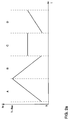
- the transmission signal s (t), the transmission frequency f of which is shown over time t in FIG. 2, is transmitted in four different blocks A, B, C and D. All four measurements are carried out sequentially, ie measurement A is carried out first, then measurement B accordingly and immediately.
- the frequency profiles of the blocks AD, which are also referred to as chirps, shown in FIGS. 2a and 2b are characterized in that the frequency profiles in the different chirps AD have different gradients m 1 , m 2 , m 3 and m 4 over time .
- An important criterion is that all four slopes m 1 to m 4 are chosen differently.
- FIG. 2a A typical course is shown in FIG. 2a, in which, in the two chirps A and B, the oscillator 1 of the radar device is controlled by a corresponding control voltage in such a way that, starting from a minimum frequency, it first generates a frequency sequence that increases linearly to a maximum value.
- the oscillator 1 generates a linear frequency sequence with an opposite slope starting from the maximum frequency, so that the minimum frequency is finally reached again.
- a linear frequency rise takes place during the chirp D starting from the minimum frequency with a slope m 4 which is half as large as the slope m 1 of the frequency curve of the chirp A is.
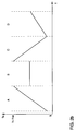
- the frequency response in Fig. 2b differs from that in Fig. 2a in that the Frequency curves of the two chirps B and C are interchanged. Furthermore further variations of the different frequency profiles are possible because the individual Chirps A-D are independent of each other and each have a separate evaluation be fed.
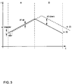
- FIG. 3 shows the curves of the transmission signal s (t) and the reflected reception signal e (t) of the measurements A and B according to FIG. 2a in a frequency-time diagram.
- L is the echo delay time
- a CW radar is characterized by the range resolution ⁇ R, by the maximum range R max , by the resolution of the speed ⁇ and by the range of the processed relative speed ⁇ Rel, min to ⁇ Rel, max .
- the transmission signal of the CW radar consists of a sequence of linear chirps of different gradients.
- Each Fourier transformation carried out after measurements A to D results in spectral lines in the respective Fourier spectra based on reflections from obstacles. If the slope m i is not equal to 0, the above-mentioned designations apply to k and l, which characterize the peak position ⁇ in the Fourier spectrum. If the slope m i is equal to 0, as is the case in the chirps C in FIG. 2a and B in FIG. 2b, the frequencies indicated by the maxima are equal to the Doppler frequencies of the obstacles. Starting from the peaks found in the Fourier spectrum, the search for potential obstacles is carried out in a distance-relative speed diagram (FIG. 4), the frequencies determined in the chirps AD each being characterized by a group of intersecting straight lines.
- FIG. 4 distance-relative speed diagram
- the straight lines A1, A2 and A3 shown in FIG. 4 relate to the chirp A, the straight lines B1, B2 and B3 to the chirp B, the straight lines C1, C2 and C3 to the chirp C and the straight lines D1, D2 and D3 to the Chirp D.
- the crossing points r i , ⁇ Rel, i found in the first step are validated by the peak positions found within the chirp C.
- the validation criterion is that there is a peak in the spectrum of the third chirp C at the frequency position ⁇ 3, q , for which the following applies: ⁇ 3, q - ⁇ 1 ⁇ ⁇ re l , i ⁇ - m 3rd ⁇ R i ⁇ R ⁇ 3, q + ⁇ 1
- an additional validation with the fourth chirp D is reduced to a very safe subset according to a similar criterion.
- the validation criterion is that there is a peak in the spectrum of the fourth chirp D at the frequency position ⁇ 4, r , for which: ⁇ 4, r - ⁇ 2nd ⁇ ⁇ re l , i ⁇ - m 4th ⁇ R i ⁇ R ⁇ 4, r + ⁇ 2nd
- intersection points validated twice in this way can then be included as a set a very low percentage of ghost targets and the corresponding ones Information can be evaluated in the subsequent data processing.
- the values of the parameters ⁇ 1 and ⁇ 2 are preferably in the range from 0.3 to 0.7, preferably in the range from 0.4 to 0.6 and in particular 0.5. This ensures that a reliable validation according to the first and second validation criteria takes place and the ghost target share in the set of calculated intersection points can be kept to a minimum.
- the values of ⁇ 1 and ⁇ 2 can preferably be the same size.
Landscapes
- Engineering & Computer Science (AREA)
- Radar, Positioning & Navigation (AREA)
- Remote Sensing (AREA)
- Physics & Mathematics (AREA)
- Computer Networks & Wireless Communication (AREA)
- General Physics & Mathematics (AREA)
- Electromagnetism (AREA)
- Radar Systems Or Details Thereof (AREA)
Applications Claiming Priority (2)
| Application Number | Priority Date | Filing Date | Title |
|---|---|---|---|
| DE19915484 | 1999-04-07 | ||
| DE19915484 | 1999-04-07 |
Publications (3)
| Publication Number | Publication Date |
|---|---|
| EP1043601A2 true EP1043601A2 (fr) | 2000-10-11 |
| EP1043601A3 EP1043601A3 (fr) | 2002-08-21 |
| EP1043601B1 EP1043601B1 (fr) | 2005-09-28 |
Family
ID=7903658
Family Applications (1)
| Application Number | Title | Priority Date | Filing Date |
|---|---|---|---|
| EP00104510A Expired - Lifetime EP1043601B1 (fr) | 1999-04-07 | 2000-03-10 | Procédé radar pour mesurer des distances et des vitesses relatives entre un véhicule et des obstacles |
Country Status (4)
| Country | Link |
|---|---|
| US (1) | US6396436B1 (fr) |
| EP (1) | EP1043601B1 (fr) |
| AT (1) | ATE305616T1 (fr) |
| DE (2) | DE19922411A1 (fr) |
Cited By (3)
| Publication number | Priority date | Publication date | Assignee | Title |
|---|---|---|---|---|
| EP2009463A2 (fr) | 2007-06-21 | 2008-12-31 | Diehl BGT Defence GmbH & Co.KG | Dispositif de sécurité pour un système d'autoprotection automatique |
| RU2508557C1 (ru) * | 2012-09-25 | 2014-02-27 | Федеральное государственное бюджетное образовательное учреждение высшего профессионального образования "Московский государственный технический университет имени Н.Э. Баумана" (МГТУ им. Н.Э. Баумана) | Радиолокационный фиксатор дальности с комбинированной частотной модуляцией и предельной регрессионной обработкой |
| CN110579770A (zh) * | 2018-06-11 | 2019-12-17 | 赫克斯冈技术中心 | 补偿速度相关的距离测量误差的双射束fmcw距离测量方法 |
Families Citing this family (37)
| Publication number | Priority date | Publication date | Assignee | Title |
|---|---|---|---|---|
| DE10026032A1 (de) * | 2000-05-25 | 2001-11-29 | Bayerische Motoren Werke Ag | Vorrichtung und Verfahren zur Abstands- und Geschwindigkeitsbestimmung |
| DE10136981A1 (de) * | 2001-07-30 | 2003-02-27 | Daimler Chrysler Ag | Verfahren und Vorrichtung zur Ermittlung eines stationären und/oder bewegten Objektes |
| US6492938B1 (en) * | 2002-02-11 | 2002-12-10 | Delphi Technologies, Inc. | Method of associating target data in a multi-slope FMCW radar system |
| US6606052B1 (en) * | 2002-03-07 | 2003-08-12 | Visteon Global Technologies, Inc. | Method and apparatus for detecting multiple objects with frequency modulated continuous wave radar |
| GB0228731D0 (en) * | 2002-12-10 | 2003-01-15 | Trw Ltd | Frequency shift keying radar with ambiguity detection |
| FR2848302B1 (fr) * | 2002-12-10 | 2005-05-27 | Thales Sa | Procede de calibration d'une source hyperfrequence |
| DE10315819A1 (de) * | 2003-04-07 | 2004-11-11 | Robert Bosch Gmbh | Verfahren und Anordnung zur Steuerung einer Fahrerassistenz-Einrichtung |
| EP1519204B1 (fr) * | 2003-09-29 | 2010-03-24 | Volkswagen Aktiengesellschaft | Radar multistatique pour véhicule |
| DE10347976A1 (de) * | 2003-10-15 | 2005-05-19 | Volkswagen Ag | Messgerät und Messverfahren für ein Kraftfahrzeug |
| DE10349919A1 (de) | 2003-10-25 | 2005-05-25 | Volkswagen Ag | Messgerät für ein Kraftfahrzeug |
| US20050096831A1 (en) * | 2003-10-31 | 2005-05-05 | Graham Turnbull | Apparatus and method for the detection of objects |
| DE10355249B4 (de) | 2003-11-26 | 2021-09-23 | Volkswagen Ag | Fahrassistenzsystem für ein Kraftfahrzeug |
| DE102004047176A1 (de) * | 2004-09-29 | 2006-04-13 | Robert Bosch Gmbh | Radarsystem für Kraftfahrzeuge |
| DE102005012945A1 (de) * | 2005-03-21 | 2006-09-28 | Robert Bosch Gmbh | Verfahren und Vorrichtung zu Abstands- und Relativgeschwindigkeitsmessung mehrerer Objekte |
| US20060238742A1 (en) * | 2005-04-25 | 2006-10-26 | Hunt Jeffrey H | Short duty cycle lidar |
| DE102006028465A1 (de) | 2006-06-21 | 2007-12-27 | Valeo Schalter Und Sensoren Gmbh | Kraftfahrzeug-Radarsystem und Verfahren zur Bestimmung von Geschwindigkeiten und Entfernungen von Objekten relativ zu dem einen Radarsystem |
| JP4697072B2 (ja) * | 2006-07-04 | 2011-06-08 | 株式会社デンソー | レーダ装置 |
| JP4977443B2 (ja) * | 2006-10-31 | 2012-07-18 | 日立オートモティブシステムズ株式会社 | レーダ装置及びレーダ検出方法 |
| DE102008034997A1 (de) | 2007-07-28 | 2009-02-26 | Volkswagen Ag | Verfahren zum Bestimmen der Azimutwinkel von Objekten in Bezug auf ein Messgerät |
| DE102007043535A1 (de) * | 2007-09-12 | 2009-03-19 | Robert Bosch Gmbh | FMCW-Radarortungsvorrichtung und entsprechendes FMCW-Radarortungsverfahren |
| GB2462148A (en) * | 2008-07-31 | 2010-02-03 | Mitsubishi Electric Inf Tech | Automotive FMCW radar with multiple frequency chirps |
| JP2010038705A (ja) * | 2008-08-05 | 2010-02-18 | Fujitsu Ten Ltd | 信号処理装置、レーダ装置、車両制御装置、及び信号処理方法 |
| US7791528B2 (en) * | 2008-11-24 | 2010-09-07 | Autoliv Asp, Inc. | Method and apparatus for radar signal processing |
| EP2189809A1 (fr) * | 2008-11-24 | 2010-05-26 | Mitsubishi Electric R&D Centre Europe B.V. | Télémétrie d'objets |
| DE102010030289A1 (de) * | 2010-06-21 | 2011-12-22 | Robert Bosch Gmbh | Radarsensor und Verfahren zum Betreiben eines Radarsensors |
| JP6275370B2 (ja) * | 2012-04-11 | 2018-02-07 | 三菱電機株式会社 | レーダ装置 |
| JP6303964B2 (ja) * | 2014-10-03 | 2018-04-04 | 株式会社デンソー | レーダ装置 |
| KR102488038B1 (ko) | 2015-11-19 | 2023-01-13 | 주식회사 에이치엘클레무브 | 차량용 레이더 장치 및 그의 타겟 결정 방법 |
| US9846228B2 (en) | 2016-04-07 | 2017-12-19 | Uhnder, Inc. | Software defined automotive radar systems |
| US10261179B2 (en) | 2016-04-07 | 2019-04-16 | Uhnder, Inc. | Software defined automotive radar |
| WO2017187304A2 (fr) * | 2016-04-25 | 2017-11-02 | Uhnder, Inc. | Radar numérique à ondes continues modulées en fréquence mettant en œuvre une modulation constante de l'enveloppe personnalisée |
| US10908272B2 (en) | 2017-02-10 | 2021-02-02 | Uhnder, Inc. | Reduced complexity FFT-based correlation for automotive radar |
| WO2018146634A1 (fr) | 2017-02-10 | 2018-08-16 | Uhnder, Inc. | Augmentation de la performance d'un pipeline de réception d'un radar avec optimisation de mémoire |
| US11105890B2 (en) | 2017-12-14 | 2021-08-31 | Uhnder, Inc. | Frequency modulated signal cancellation in variable power mode for radar applications |
| JPWO2020003349A1 (ja) * | 2018-06-25 | 2021-06-24 | 株式会社ソシオネクスト | 周波数掃引回路およびレーダー装置 |
| US11047972B2 (en) * | 2019-01-28 | 2021-06-29 | Steradian Semiconductors Private Limited | Method, apparatus and device for determining a velocity of an object in a time switched MIMO radar system |
| US11933876B2 (en) * | 2020-06-11 | 2024-03-19 | Qualcomm Incorporated | Combined frequency modulated continuous wave radar detection |
Citations (6)
| Publication number | Priority date | Publication date | Assignee | Title |
|---|---|---|---|---|
| US5212489A (en) * | 1991-03-18 | 1993-05-18 | Hydroacoustics Inc. | Echo ranging system for detecting velocity of targets using composite doppler invariant transmissions |
| EP0557945A2 (fr) * | 1992-02-25 | 1993-09-01 | Hughes Aircraft Company | Télémètre, détection et résolution dans un système radar à forme d'onde modulée en fréquence en pente multiple |
| US5268692A (en) * | 1991-03-14 | 1993-12-07 | Grosch Theodore O | Safe stopping distance detector, antenna and method |
| DE4244608A1 (de) * | 1992-12-31 | 1994-07-07 | Volkswagen Ag | Computerisiertes Radarverfahren zur Messung von Abständen und Relativgeschwindigkeiten zwischen einem Fahrzeug und vor ihm befindlichen Hindernissen |
| DE19602437A1 (de) * | 1995-01-24 | 1996-07-25 | Nippon Denso Co | Frequenzmoduliertes Dauerstrichradarsystem |
| DE19538309A1 (de) * | 1995-10-14 | 1997-04-17 | Volkswagen Ag | Radarverfahren zur Messung von Abständen und Relativgeschwindigkeiten zwischen einem Fahrzeug und einem oder mehreren Hindernissen |
Family Cites Families (6)
| Publication number | Priority date | Publication date | Assignee | Title |
|---|---|---|---|---|
| US5767793A (en) * | 1995-04-21 | 1998-06-16 | Trw Inc. | Compact vehicle based rear and side obstacle detection system including multiple antennae |
| JP3627389B2 (ja) * | 1995-09-28 | 2005-03-09 | 株式会社デンソー | レーダ装置 |
| US5969667A (en) * | 1997-10-16 | 1999-10-19 | Automotive Systems Laboratory, Inc. | Radar system |
| US5959570A (en) * | 1997-11-21 | 1999-09-28 | Raytheon Company | Automotive forward looking sensor blockage detection system and related techniques |
| US5929802A (en) * | 1997-11-21 | 1999-07-27 | Raytheon Company | Automotive forward looking sensor application |
| US6121915A (en) * | 1997-12-03 | 2000-09-19 | Raytheon Company | Random noise automotive radar system |
-
1999
- 1999-05-14 DE DE19922411A patent/DE19922411A1/de not_active Withdrawn
-
2000
- 2000-03-10 DE DE50011232T patent/DE50011232D1/de not_active Expired - Lifetime
- 2000-03-10 AT AT00104510T patent/ATE305616T1/de not_active IP Right Cessation
- 2000-03-10 EP EP00104510A patent/EP1043601B1/fr not_active Expired - Lifetime
- 2000-04-07 US US09/545,528 patent/US6396436B1/en not_active Expired - Lifetime
Patent Citations (6)
| Publication number | Priority date | Publication date | Assignee | Title |
|---|---|---|---|---|
| US5268692A (en) * | 1991-03-14 | 1993-12-07 | Grosch Theodore O | Safe stopping distance detector, antenna and method |
| US5212489A (en) * | 1991-03-18 | 1993-05-18 | Hydroacoustics Inc. | Echo ranging system for detecting velocity of targets using composite doppler invariant transmissions |
| EP0557945A2 (fr) * | 1992-02-25 | 1993-09-01 | Hughes Aircraft Company | Télémètre, détection et résolution dans un système radar à forme d'onde modulée en fréquence en pente multiple |
| DE4244608A1 (de) * | 1992-12-31 | 1994-07-07 | Volkswagen Ag | Computerisiertes Radarverfahren zur Messung von Abständen und Relativgeschwindigkeiten zwischen einem Fahrzeug und vor ihm befindlichen Hindernissen |
| DE19602437A1 (de) * | 1995-01-24 | 1996-07-25 | Nippon Denso Co | Frequenzmoduliertes Dauerstrichradarsystem |
| DE19538309A1 (de) * | 1995-10-14 | 1997-04-17 | Volkswagen Ag | Radarverfahren zur Messung von Abständen und Relativgeschwindigkeiten zwischen einem Fahrzeug und einem oder mehreren Hindernissen |
Cited By (4)
| Publication number | Priority date | Publication date | Assignee | Title |
|---|---|---|---|---|
| EP2009463A2 (fr) | 2007-06-21 | 2008-12-31 | Diehl BGT Defence GmbH & Co.KG | Dispositif de sécurité pour un système d'autoprotection automatique |
| EP2009463A3 (fr) * | 2007-06-21 | 2009-07-22 | Diehl BGT Defence GmbH & Co.KG | Dispositif de sécurité pour un système d'autoprotection automatique |
| RU2508557C1 (ru) * | 2012-09-25 | 2014-02-27 | Федеральное государственное бюджетное образовательное учреждение высшего профессионального образования "Московский государственный технический университет имени Н.Э. Баумана" (МГТУ им. Н.Э. Баумана) | Радиолокационный фиксатор дальности с комбинированной частотной модуляцией и предельной регрессионной обработкой |
| CN110579770A (zh) * | 2018-06-11 | 2019-12-17 | 赫克斯冈技术中心 | 补偿速度相关的距离测量误差的双射束fmcw距离测量方法 |
Also Published As
| Publication number | Publication date |
|---|---|
| ATE305616T1 (de) | 2005-10-15 |
| EP1043601B1 (fr) | 2005-09-28 |
| EP1043601A3 (fr) | 2002-08-21 |
| US6396436B1 (en) | 2002-05-28 |
| DE50011232D1 (de) | 2006-02-09 |
| DE19922411A1 (de) | 2000-10-12 |
Similar Documents
| Publication | Publication Date | Title |
|---|---|---|
| EP1043601B1 (fr) | Procédé radar pour mesurer des distances et des vitesses relatives entre un véhicule et des obstacles | |
| EP1325350B1 (fr) | Procede et dispositif pour determiner l'eloignement d'un objet eloigne et la vitesse relative de celui-ci | |
| DE4244608C2 (de) | Mittels eines Computers durchgeführtes Radarverfahren zur Messung von Abständen und Relativgeschwindigkeiten zwischen einem Fahrzeug und vor ihm befindlichen Hindernissen | |
| EP0727051B1 (fr) | Radar et procede permettant de le faire fonctionner | |
| EP3161510B1 (fr) | Procédé de mesure par radar | |
| EP1797448B1 (fr) | Procede de verification d'objets dans des systèmes de radar pour des vehicules à moteur | |
| EP1864155B1 (fr) | Procede et dispositif de mesure de distance et de vitesse relative de plusieurs objets | |
| DE19538309C2 (de) | Radarverfahren zur Messung von Abständen und Relativgeschwindigkeiten zwischen einem Fahrzeug und einem oder mehreren Hindernissen | |
| EP1761800B1 (fr) | Capteur radar et procede pour evaluer des objets | |
| EP2126603B1 (fr) | Procédé pour radar FMCW avec évaluation de la phase des signaux différentiels | |
| EP0533220B1 (fr) | Méthode pour distinguer au moins deux objectifs spécialement pour radars Doppler HPRF | |
| DE102017105783B4 (de) | Verfahren zum Bestimmen eines Abstandes und einer Geschwindigkeit eines Objektes | |
| WO2008040341A1 (fr) | Système radar destiné au balayage de l'environnement avec compensation de signaux parasites | |
| EP2755045A1 (fr) | Procédé de mesure cyclique de distances et de vitesses d'objets à l'aide d'un détecteur radar à onde continue à fréquence modulée (FMCW) | |
| DE69310004T2 (de) | Verfahren und Vorrichtung zur Feststellung des Erreichens eines vorausbestimmten Abstandes eines Punktreflektors mittels der Laufzeit einer kontinuierlichen Welle | |
| WO2019170347A1 (fr) | Procédé de détermination univoque de la vitesse d'un objet dans un système de mesure radar | |
| EP1877825B1 (fr) | Procede et dispositif pour determiner une distance par rapport a un objet cible | |
| EP0919834B1 (fr) | Procédé pour détecter une cible utilisant un radar HPRF | |
| DE102009045677A1 (de) | FMCW-Radarsensor für Kraftfahrzeuge | |
| EP0616232B1 (fr) | Radar pour trafic | |
| EP2196823A1 (fr) | Procédé de détermination de la distance entre deux objets | |
| EP0730166A1 (fr) | Procédé et dispositif pour la mesure du trafic routier utilisant un appareil radar | |
| EP0791838A1 (fr) | Procédé de mesure de la vitesse d'un cible-radar | |
| EP2182380A1 (fr) | Procédé de détection de la superposition de pointe dans un spectre discret d'un signal de repérage | |
| EP2096461A1 (fr) | Dispositif de mesure et procédé de mesure destinés à la détermination d'un intervalle, d'une vitesse, d'une accélération, d'un mouvement brusque, d'un angle d'entrée, d'une vitesse d'angle d'entrée, d'une accélération d'angle d'entrée et/ou d'un mouvement brusque d'angle d'entrée entre un dispositif d'émission et de réception et un objet |
Legal Events
| Date | Code | Title | Description |
|---|---|---|---|
| PUAI | Public reference made under article 153(3) epc to a published international application that has entered the european phase |
Free format text: ORIGINAL CODE: 0009012 |
|
| AK | Designated contracting states |
Kind code of ref document: A2 Designated state(s): AT BE CH CY DE DK ES FI FR GB GR IE IT LI LU MC NL PT SE |
|
| AX | Request for extension of the european patent |
Free format text: AL;LT;LV;MK;RO;SI |
|
| PUAL | Search report despatched |
Free format text: ORIGINAL CODE: 0009013 |
|
| AK | Designated contracting states |
Kind code of ref document: A3 Designated state(s): AT BE CH CY DE DK ES FI FR GB GR IE IT LI LU MC NL PT SE |
|
| AX | Request for extension of the european patent |
Free format text: AL;LT;LV;MK;RO;SI |
|
| RIC1 | Information provided on ipc code assigned before grant |
Free format text: 7G 01S 13/93 A, 7G 01S 13/58 B, 7G 01S 13/34 B |
|
| 17P | Request for examination filed |
Effective date: 20030221 |
|
| 17Q | First examination report despatched |
Effective date: 20030320 |
|
| AKX | Designation fees paid |
Designated state(s): AT BE CH CY DE DK ES FI FR GB GR IE IT LI LU MC NL PT SE |
|
| GRAP | Despatch of communication of intention to grant a patent |
Free format text: ORIGINAL CODE: EPIDOSNIGR1 |
|
| RIC1 | Information provided on ipc code assigned before grant |
Ipc: 7G 01S 13/34 B Ipc: 7G 01S 13/93 A |
|
| GRAS | Grant fee paid |
Free format text: ORIGINAL CODE: EPIDOSNIGR3 |
|
| GRAA | (expected) grant |
Free format text: ORIGINAL CODE: 0009210 |
|
| AK | Designated contracting states |
Kind code of ref document: B1 Designated state(s): AT BE CH CY DE DK ES FI FR GB GR IE IT LI LU MC NL PT SE |
|
| PG25 | Lapsed in a contracting state [announced via postgrant information from national office to epo] |
Ref country code: IT Free format text: LAPSE BECAUSE OF FAILURE TO SUBMIT A TRANSLATION OF THE DESCRIPTION OR TO PAY THE FEE WITHIN THE PRESCRIBED TIME-LIMIT;WARNING: LAPSES OF ITALIAN PATENTS WITH EFFECTIVE DATE BEFORE 2007 MAY HAVE OCCURRED AT ANY TIME BEFORE 2007. THE CORRECT EFFECTIVE DATE MAY BE DIFFERENT FROM THE ONE RECORDED. Effective date: 20050928 Ref country code: NL Free format text: LAPSE BECAUSE OF FAILURE TO SUBMIT A TRANSLATION OF THE DESCRIPTION OR TO PAY THE FEE WITHIN THE PRESCRIBED TIME-LIMIT Effective date: 20050928 Ref country code: IE Free format text: LAPSE BECAUSE OF FAILURE TO SUBMIT A TRANSLATION OF THE DESCRIPTION OR TO PAY THE FEE WITHIN THE PRESCRIBED TIME-LIMIT Effective date: 20050928 Ref country code: FI Free format text: LAPSE BECAUSE OF FAILURE TO SUBMIT A TRANSLATION OF THE DESCRIPTION OR TO PAY THE FEE WITHIN THE PRESCRIBED TIME-LIMIT Effective date: 20050928 |
|
| REG | Reference to a national code |
Ref country code: GB Ref legal event code: FG4D Free format text: NOT ENGLISH |
|
| REG | Reference to a national code |
Ref country code: CH Ref legal event code: EP |
|
| REG | Reference to a national code |
Ref country code: IE Ref legal event code: FG4D Free format text: LANGUAGE OF EP DOCUMENT: GERMAN |
|
| GBT | Gb: translation of ep patent filed (gb section 77(6)(a)/1977) |
Effective date: 20051128 |
|
| PG25 | Lapsed in a contracting state [announced via postgrant information from national office to epo] |
Ref country code: SE Free format text: LAPSE BECAUSE OF FAILURE TO SUBMIT A TRANSLATION OF THE DESCRIPTION OR TO PAY THE FEE WITHIN THE PRESCRIBED TIME-LIMIT Effective date: 20051228 Ref country code: DK Free format text: LAPSE BECAUSE OF FAILURE TO SUBMIT A TRANSLATION OF THE DESCRIPTION OR TO PAY THE FEE WITHIN THE PRESCRIBED TIME-LIMIT Effective date: 20051228 Ref country code: GR Free format text: LAPSE BECAUSE OF FAILURE TO SUBMIT A TRANSLATION OF THE DESCRIPTION OR TO PAY THE FEE WITHIN THE PRESCRIBED TIME-LIMIT Effective date: 20051228 |
|
| PG25 | Lapsed in a contracting state [announced via postgrant information from national office to epo] |
Ref country code: ES Free format text: LAPSE BECAUSE OF FAILURE TO SUBMIT A TRANSLATION OF THE DESCRIPTION OR TO PAY THE FEE WITHIN THE PRESCRIBED TIME-LIMIT Effective date: 20060108 |
|
| REF | Corresponds to: |
Ref document number: 50011232 Country of ref document: DE Date of ref document: 20060209 Kind code of ref document: P |
|
| PG25 | Lapsed in a contracting state [announced via postgrant information from national office to epo] |
Ref country code: PT Free format text: LAPSE BECAUSE OF FAILURE TO SUBMIT A TRANSLATION OF THE DESCRIPTION OR TO PAY THE FEE WITHIN THE PRESCRIBED TIME-LIMIT Effective date: 20060228 |
|
| NLV1 | Nl: lapsed or annulled due to failure to fulfill the requirements of art. 29p and 29m of the patents act | ||
| PG25 | Lapsed in a contracting state [announced via postgrant information from national office to epo] |
Ref country code: AT Free format text: LAPSE BECAUSE OF NON-PAYMENT OF DUE FEES Effective date: 20060310 |
|
| PG25 | Lapsed in a contracting state [announced via postgrant information from national office to epo] |
Ref country code: CH Free format text: LAPSE BECAUSE OF NON-PAYMENT OF DUE FEES Effective date: 20060331 Ref country code: LU Free format text: LAPSE BECAUSE OF NON-PAYMENT OF DUE FEES Effective date: 20060331 Ref country code: BE Free format text: LAPSE BECAUSE OF NON-PAYMENT OF DUE FEES Effective date: 20060331 Ref country code: MC Free format text: LAPSE BECAUSE OF NON-PAYMENT OF DUE FEES Effective date: 20060331 Ref country code: LI Free format text: LAPSE BECAUSE OF NON-PAYMENT OF DUE FEES Effective date: 20060331 |
|
| REG | Reference to a national code |
Ref country code: IE Ref legal event code: FD4D |
|
| ET | Fr: translation filed | ||
| PLBE | No opposition filed within time limit |
Free format text: ORIGINAL CODE: 0009261 |
|
| STAA | Information on the status of an ep patent application or granted ep patent |
Free format text: STATUS: NO OPPOSITION FILED WITHIN TIME LIMIT |
|
| 26N | No opposition filed |
Effective date: 20060629 |
|
| REG | Reference to a national code |
Ref country code: CH Ref legal event code: PL |
|
| BERE | Be: lapsed |
Owner name: VOLKSWAGEN A.G. Effective date: 20060331 |
|
| PG25 | Lapsed in a contracting state [announced via postgrant information from national office to epo] |
Ref country code: CY Free format text: LAPSE BECAUSE OF FAILURE TO SUBMIT A TRANSLATION OF THE DESCRIPTION OR TO PAY THE FEE WITHIN THE PRESCRIBED TIME-LIMIT Effective date: 20050928 |
|
| PGFP | Annual fee paid to national office [announced via postgrant information from national office to epo] |
Ref country code: GB Payment date: 20140331 Year of fee payment: 15 |
|
| GBPC | Gb: european patent ceased through non-payment of renewal fee |
Effective date: 20150310 |
|
| PG25 | Lapsed in a contracting state [announced via postgrant information from national office to epo] |
Ref country code: GB Free format text: LAPSE BECAUSE OF NON-PAYMENT OF DUE FEES Effective date: 20150310 |
|
| REG | Reference to a national code |
Ref country code: FR Ref legal event code: PLFP Year of fee payment: 17 |
|
| REG | Reference to a national code |
Ref country code: FR Ref legal event code: PLFP Year of fee payment: 18 |
|
| REG | Reference to a national code |
Ref country code: FR Ref legal event code: PLFP Year of fee payment: 19 |
|
| PGFP | Annual fee paid to national office [announced via postgrant information from national office to epo] |
Ref country code: FR Payment date: 20190328 Year of fee payment: 20 Ref country code: DE Payment date: 20190331 Year of fee payment: 20 |
|
| REG | Reference to a national code |
Ref country code: DE Ref legal event code: R071 Ref document number: 50011232 Country of ref document: DE |
|
| P01 | Opt-out of the competence of the unified patent court (upc) registered |
Effective date: 20230523 |