EP1043437A1 - Nonwoven fabric making apparatus - Google Patents
Nonwoven fabric making apparatus Download PDFInfo
- Publication number
- EP1043437A1 EP1043437A1 EP00302864A EP00302864A EP1043437A1 EP 1043437 A1 EP1043437 A1 EP 1043437A1 EP 00302864 A EP00302864 A EP 00302864A EP 00302864 A EP00302864 A EP 00302864A EP 1043437 A1 EP1043437 A1 EP 1043437A1
- Authority
- EP
- European Patent Office
- Prior art keywords
- axis
- nozzles
- nozzle
- nonwoven fabric
- nozzle arrays
- Prior art date
- Legal status (The legal status is an assumption and is not a legal conclusion. Google has not performed a legal analysis and makes no representation as to the accuracy of the status listed.)
- Granted
Links
- 239000004745 nonwoven fabric Substances 0.000 title claims abstract description 28
- 239000012530 fluid Substances 0.000 claims abstract description 17
- 239000000835 fiber Substances 0.000 claims abstract description 16
- 238000003491 array Methods 0.000 claims description 38
- 230000015572 biosynthetic process Effects 0.000 description 2
- 230000007423 decrease Effects 0.000 description 2
- 230000010355 oscillation Effects 0.000 description 2
- 239000004743 Polypropylene Substances 0.000 description 1
- 238000010276 construction Methods 0.000 description 1
- 230000003111 delayed effect Effects 0.000 description 1
- 230000001788 irregular Effects 0.000 description 1
- 238000000034 method Methods 0.000 description 1
- -1 polypropylene Polymers 0.000 description 1
- 229920001155 polypropylene Polymers 0.000 description 1
- 230000002618 waking effect Effects 0.000 description 1
Images




Classifications
-
- D—TEXTILES; PAPER
- D04—BRAIDING; LACE-MAKING; KNITTING; TRIMMINGS; NON-WOVEN FABRICS
- D04H—MAKING TEXTILE FABRICS, e.g. FROM FIBRES OR FILAMENTARY MATERIAL; FABRICS MADE BY SUCH PROCESSES OR APPARATUS, e.g. FELTS, NON-WOVEN FABRICS; COTTON-WOOL; WADDING ; NON-WOVEN FABRICS FROM STAPLE FIBRES, FILAMENTS OR YARNS, BONDED WITH AT LEAST ONE WEB-LIKE MATERIAL DURING THEIR CONSOLIDATION
- D04H17/00—Felting apparatus
-
- D—TEXTILES; PAPER
- D04—BRAIDING; LACE-MAKING; KNITTING; TRIMMINGS; NON-WOVEN FABRICS
- D04H—MAKING TEXTILE FABRICS, e.g. FROM FIBRES OR FILAMENTARY MATERIAL; FABRICS MADE BY SUCH PROCESSES OR APPARATUS, e.g. FELTS, NON-WOVEN FABRICS; COTTON-WOOL; WADDING ; NON-WOVEN FABRICS FROM STAPLE FIBRES, FILAMENTS OR YARNS, BONDED WITH AT LEAST ONE WEB-LIKE MATERIAL DURING THEIR CONSOLIDATION
- D04H1/00—Non-woven fabrics formed wholly or mainly of staple fibres or like relatively short fibres
- D04H1/40—Non-woven fabrics formed wholly or mainly of staple fibres or like relatively short fibres from fleeces or layers composed of fibres without existing or potential cohesive properties
- D04H1/44—Non-woven fabrics formed wholly or mainly of staple fibres or like relatively short fibres from fleeces or layers composed of fibres without existing or potential cohesive properties the fleeces or layers being consolidated by mechanical means, e.g. by rolling
- D04H1/46—Non-woven fabrics formed wholly or mainly of staple fibres or like relatively short fibres from fleeces or layers composed of fibres without existing or potential cohesive properties the fleeces or layers being consolidated by mechanical means, e.g. by rolling by needling or like operations to cause entanglement of fibres
- D04H1/492—Non-woven fabrics formed wholly or mainly of staple fibres or like relatively short fibres from fleeces or layers composed of fibres without existing or potential cohesive properties the fleeces or layers being consolidated by mechanical means, e.g. by rolling by needling or like operations to cause entanglement of fibres by fluid jet
Definitions
- This invention relates to a nonwoven fabric making apparatus particularly to make nonwoven fabrics.
- nonwoven fabric making apparatus particularly to make nonwoven fabrics by continuously feeding a fibrous web on a conveyor belt moving at a predetermined velocity, ejecting streams of high pressure fluid from a plurality of nozzles against the upper surface of the web, and thereby entangling component fibers of the web together to form nonwoven fabrics.
- Japanese Patent Application Disclosure No. 1994-207360 describes a nonwoven fabric making apparatus comprising a nozzle head adapted to eject streams of high pressure fluid against a fibrous web travelling in a given direction.
- the nozzle head is supported by a pair of oscillating bearings so that the nozzle head may be movable back and forth in its axial direction.
- the nozzle head may be reciprocated at uneven amplitudes transversely of the direction in which the web travels in the course of ejecting the streams of high pressure fluid.
- the Japanese Patent Application Disclosure No. 1994-207360 intends to alleviate the formation of impact traces on the fiber entangled sheet.
- a nonwoven fabric making apparatus having a Y-axis and an X-axis intersecting the Y-axis, the apparatus comprising a plurality of nozzles adapted to eject streams of high pressure fluid against at least one surface of a fibrous web continuously traveling in a direction of the Y-axis, to entangle component fibers of the web, the nozzles being arranged at predetermined intervals in a direction of the X-axis to form a straightly extending first nozzle array declined at a predetermined angle with respect to the Y-axis.
- a predetermined number (n) of nozzles are arranged at predetermined intervals in said directions of the Y-and X-axes so that the predetermined number (n) of nozzles define second - nth nozzle arrays extending parallel to the first nozzle array in the direction of the X-axis.
- the second - nth nozzle arrays are successively spaced from the first nozzle array and one from another and the predetermined number (n) of nozzles defining the second - nth nozzle arrays lie at positions bisecting a length between each pair of adjacent nozzles in the first nozzle array, wherein a declination angle ⁇ 2 of the first - nth nozzle arrays with respect to the Y-axis is given by in which
- Fig. 1 is a plan view showing a nozzle support member 1 making an important part of a nonwoven fabric making apparatus with a portion of a web 30 lying on the support member 1 being cutaway. While an entire construction is not illustrated, the apparatus has the support member 1 formed with a plurality of nozzles 20. High pressure fluid is ejected through fine orifices (not shown) of the respective nozzles 20 against at least one surface of the web 30 so that component fibers of the web 30 may be entangled to form a predetermined nonwoven fabric. Details of a technique to entangle the component fibers by ejection of high pressure fluid will be apparent from various documents such as the Japanese Patent Application Disclosure No. 1994-207360.
- a Y-axis extending in a direction as indicated by an arrow along which the web 30 travels and an X-axis intersecting the Y-axis at right angles, i.e., extending transversely of the web 30.
- These Y-axis and X-axis form coordinates.
- the web 30 is continuously fed in the direction of the arrow parallel to the Y-axis.
- the support member 1 is formed with a first nozzle array R1 comprising a plurality of nozzles 20 arranged at regular intervals transversely (in the direction of the X-axis) of the support member 1. Centers of the respective nozzles 20 constituting the first nozzle array R1 lie on a single dotted chain line L1 straightly extending transversely of the support member 1. The center O1 of the nozzle 20a lying in the middle of the first nozzle array R1 corresponds to the origin of the coordinates.
- the support member 1 is fixedly mounted on the apparatus with the first nozzle array R1 declined with respect to both the Y-axis and the X-axis.
- the first nozzle array R1 can be divided in two groups, i.e., the group of the nozzles 20 lying on the left hand with respect to the middle nozzle 20a and the group of the nozzles 20 lying on the right hand with respect to the middle nozzle 20a.
- the left hand group of the nozzles 20 lies in the second quadrant and the right hand group of the nozzles 20 lies the fourth quadrant.
- straight lines Y1, Y2 indicated by two dotted chain lines, respectively, extend parallel to the Y-axis and the respective nozzles 20b adjacent the middle nozzle 20a lie on these straight lines Y1, Y2.
- a right-angled triangle 2 is represented.
- This right-angled triangle 2 is defined by: an oblique line 2a connecting the centers O1, O2 of the nozzle 20a lying on the origin and the nozzle 20b adjacent this nozzle 20a; a horizontal line 2b connecting the center O2 of said nozzle 20b to the Y-axis and extending in parallel to the X-axis; and a perpendicular line 2c extending on the Y-axis from the center O1 of the nozzle 20a to said horizontal line 2b.
- Fig. 2 is a scale-enlarged plan view of a right-angled triangle 2 represented on the coordinates of Fig. 1.
- the first nozzle array R1 is declined with respect to the Y-axis at an angle ⁇ 1 included between the oblique line 2a and perpendicular line 2c.
- a distance P between the Y-axis and the straight line Y1 projected on the X-axis i.e., a length of the horizontal line 2b as one side of the triangle 2
- P A 1 sin ⁇ 1
- a 1 represents a length of the oblique line 2a
- ⁇ 1 represents an angle at which the first nozzle array R1 is declined with respect to the Y-axis.
- Value P is preferably in a range of 0.1 - 0.25 mm. P's value less than 0.1 mm would cause all the nozzles 20 to overlap one upon another. The value P larger than 0.25 mm would result in a nonwoven fabric having impact traces left thereon.
- an appropriate angle ⁇ 1 to define the value P in the range may be obtained on the basis of the equation 1 since the length A 1 is predetermined.
- an appropriate length A 1 to define the value P in the range may be obtained on the basis of the equation 1.
- component fibers of the web 30 are moved in opposite sides of the respective spots in the direction of the X-axis.
- the component fibers thus forcibly moved are closely gathers between each pair of adjacent spots corresponding to each pair of adjacent nozzles 20a and 20b to form high density regions. These high density regions appear as stripe-like impact traces on the finished nonwoven fabric.
- the angle ⁇ 1 of the first nozzle array R1 with respect to the Y-axis may be selectively reduced to correspondingly reduce the value P and thereby to adjustably close respective streams of fluid ejected against the web 30.
- fluid ejection from the nozzle 2a may be slightly delayed with respect to the adjacent nozzles 2b to hit the spots at which the component fibers have been closely gathered. In this manner, the component fibers once closely gathered can be moved back and undesirable impact traces can be erased.
- Parallel to the Y-axis the respective streams of high pressure fluid continuously hit the corresponding regions of the web 30 and thereby ensure the component fibers to be sufficiently entangled together.
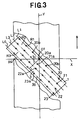
- Fig. 3 is a plan view the support member 1 realized in a manner different from that shown by Fig. 1.
- This support member 1 is formed with, in addition to the first nozzle array R1, second - fourth nozzle arrays R2, R3, R4 arranged transversely of the support meter 1 successively parallel to said first nozzle array R1.
- the support member 1 is fixedly mounted on the apparatus with these first - fourth nozzle arrays R1, R2, R3, R4 declined at a predetermined angle with respect to the Y-axis.
- centers of the respective nozzles 20, 21, 22, 23 constituting the first - fourth nozzle arrays R1, R2, R3, R4 lie on single dotted chain lines L1, L2, L3, L4 straightly extending transversely of the support member 1.
- the center O1 of the nozzle 20a lying in the middle of the first nozzle array R1 corresponds to the origin at the coordinates.
- a right-angled triangle 3 is represented in the third quadrant of the coordinates.
- This right-angled triangle 3 is defined by: an oblique line 3a extending along the Y-axis from the centers O1 of the nozzle 20a lying on the origin; a horizontal line 3b extending along the single dotted chain line L4 of the fourth nozzle array R4; and a perpendicular line 3c extending from the center O1 of the nozzle 20a to the horizontal line 3b.
- Fig. 4 is a scale-enlarged plan view showing the right-angled triangle 3 represented on the coordinates of Fig. 3.
- the first - fourth nozzle arrays R1, R2, R3, R4 are arranged at regular distances of B in the direction of the Y-axis and the nozzles 20a, 20b of the first nozzle array R1 are spaced one from another by a length A 2 transversely of the support member 1 (i.e., in the direction of the X-axis).
- Three nozzles 21a, 22a, 23a of the second - fourth nozzle arrays R2, R3, R4 arranged in the direction of the Y-axis are successively spaced one from another by a length C transversely of the support member 1 so as to bisect the length A 2 between each pair of adjacent nozzles 20a, 20b of the first nozzle array R1. Accordingly, the nozzle 21a and the nozzle 21 of the second nozzle array R2, the nozzle 22a and the nozzle 22 of the third nozzle array R3, and the nozzle 23a and the nozzle 23 of the fourth nozzle array R4 are respectively spaced one from another by the length A 2 transversely of the support member 1.
- the centers O1, O3, O4, O5 of the nozzles 20a, 21a, 22a, 23a are successively spaced one from another by a distance P between the Y-axis and the straight line Y1 projected on the X-axis or a distance P projected on the X-axis by which the respective straight lines Y2, Y3, Y4 are successively spaced one from another.
- the distance P is smaller than the length C.
- An angle ⁇ 2 of the triangle 3 at which the nozzle array decline with respect to the Y-axis is given by the following equation: wherein A 2 represents a length of a segment extending between the centers O1, O2 of each pair of adjacent nozzles 20a, 20b in the first nozzle array R1, B represents a length by which the respective nozzle arrays R1, R2, R3, R4 are successively spaced one from another in the direction of the Y-axis, and n represents the number of the nozzles 20, 21, 22, 23 arranged in the direction of the Y-axis.
- Fig. 5 is a scale-enlarged plan view showing a right-angled triangle similar to the triangle 3 represented in Fig. 4.
- This triangle 4 is defined by an oblique line 4a extending along the single dotted chain line L4 of the fourth nozzle array R4, a perpendicular line 4c along the Y-axis and a horizontal line 4b extending parallel to the X-axis from the center O5 of the nozzle 23 to the Y-axis.
- the triangle 4 is similar to the triangle 3 and therefore the angle ⁇ 2 of the triangle 4 is identical to the angle ⁇ 2 of the triangle 3.
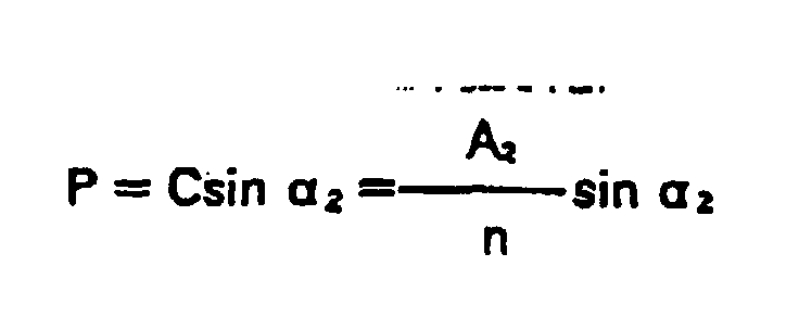
- a distance P between the Y-axis and the straight line Y1 measured as projected on the X-axis is given by the following equation: wherein C represents a length by which the respective nozzle arrays R1, R2, R3, R4 are successively spaced one from another transversely of the support member 1.
- a declination of the respective nozzle arrays with respect to the Y-axis can be determined according to the equation (2) so far as the remaining factors are given.
- the remaining factors are the length A 2 of the segment extending between the centers O1, O2 of each pair of adjacent nozzles 20a, 20b in the first nozzle array R1, the length B by which the respective nozzle arrays are successively spaced one from another, and the number of the nozzles arranged in the direction of the Y-axis.
- a distance P between each pair of adjacent two dotted chain lines measured as projected on the X-axis can be determined according to the equation (3).
- the nozzles are not essential to arrange the nozzles on the support member 1 at regular intervals and it is also possible to arrange them at irregular intervals so far as the value P is in the range of 0.1 - 0.25 mm.
- the number of the nozzle arrays also is not limited to the number as described and illustrated. For example, two, three, four more nozzle arrays may formed on the support member 1.
- Fig. 6 is a fragmentary plan view of a nonwoven fabric made by using the apparatus provided with the support member 1 shown by Fig. 3.
- Continuous fiber of polypropylene having a basis weight of 20 g/m 2 was used as the web 30 constituting the nonwoven fabric.
- the apparatus was operated under a condition that the web 30 should travel at a velocity of 40 m/sec and fluid should be ejected only once against the upper surface of the web 30 under a pressure of 100 kg/cm 2 .
- the nonwoven fabric waking apparatus enables the component fibers of the web to be sufficiently entangled together without leaving the impact traces by the high pressure fluid on the nonwoven fabric. It is necessary for the apparatus according to this invention merely to decline the support member formed with the nozzle arrays with respect to the direction in which the web travels. It is unnecessary for the apparatus according to this invention to rearrange the nozzles and/or to increase the number of the nozzle arrays. Accordingly, the existing apparatus may be modified to obtain the apparatus equivalent to the apparatus of this invention.
Landscapes
- Engineering & Computer Science (AREA)
- Textile Engineering (AREA)
- Mechanical Engineering (AREA)
- Nonwoven Fabrics (AREA)
Abstract
Description
- This invention relates to a nonwoven fabric making apparatus particularly to make nonwoven fabrics.
- There has already been developed a nonwoven fabric making apparatus particularly to make nonwoven fabrics by continuously feeding a fibrous web on a conveyor belt moving at a predetermined velocity, ejecting streams of high pressure fluid from a plurality of nozzles against the upper surface of the web, and thereby entangling component fibers of the web together to form nonwoven fabrics.
- Japanese Patent Application Disclosure No. 1994-207360 describes a nonwoven fabric making apparatus comprising a nozzle head adapted to eject streams of high pressure fluid against a fibrous web travelling in a given direction. The nozzle head is supported by a pair of oscillating bearings so that the nozzle head may be movable back and forth in its axial direction. The nozzle head may be reciprocated at uneven amplitudes transversely of the direction in which the web travels in the course of ejecting the streams of high pressure fluid.
- The Japanese Patent Application Disclosure No. 1994-207360 intends to alleviate the formation of impact traces on the fiber entangled sheet.
- While the Japanese Patent Application Disclosure No. 1994-207360 intends to solve this problem of impact traces by unevenly oscillating the nozzle head, a pattern is still formed by the oscillation at the uneven amplitude occurring transversely of the sheet. Consequently, the formation of bellows-like impact traces is inevitable.
- Oscillation of the nozzle head at a relatively high velocity would make it impossible to focus the stream of high pressure fluid to desired spots on the web and thereby to entangle component fibers closely together.
- It is an object of this invention to provide a nonwoven fabric making apparatus enabling component fibers of a web to be reliably entangled without any impact traces by streams of high pressure fluid thereon.
- According to this invention, there is provided a nonwoven fabric making apparatus having a Y-axis and an X-axis intersecting the Y-axis, the apparatus comprising a plurality of nozzles adapted to eject streams of high pressure fluid against at least one surface of a fibrous web continuously traveling in a direction of the Y-axis, to entangle component fibers of the web, the nozzles being arranged at predetermined intervals in a direction of the X-axis to form a straightly extending first nozzle array declined at a predetermined angle with respect to the Y-axis.
- According to one preferred embodiment of this invention, the respective nozzles of the first nozzle array are arranged at regular intervals in the direction of the X-axis and a plurality of straight lines extending parallel to the Y-axis to connect centers of corresponding nozzles in the respective nozzle arrays in alignment are successively spaced one from another by a distance P given by
- A1: a length of the segment extending between centers of a pair of adjacent nozzles, and
- α1: a declination angle of the first nozzle array with respect to the Y-axis, and wherein the distance P is in a range of 0.1 - 0.25 mm.
-
- According to another preferred embodiment of this invention, between the each pair of adjacent nozzles in the first nozzle array, a predetermined number (n) of nozzles are arranged at predetermined intervals in said directions of the Y-and X-axes so that the predetermined number (n) of nozzles define second - nth nozzle arrays extending parallel to the first nozzle array in the direction of the X-axis.
- According to still another embodiment of this invention, the second - nth nozzle arrays are successively spaced from the first nozzle array and one from another and the predetermined number (n) of nozzles defining the second - nth nozzle arrays lie at positions bisecting a length between each pair of adjacent nozzles in the first nozzle array, wherein a declination angle α2 of the first - nth nozzle arrays with respect to the Y-axis is given byin which

- α2: declination angle of the nozzle arrays with respect to the Y-axis,
- A2: length of a segment connecting centers of each pair of adjacent nozzles in the first nozzle array,
- B: distance between each pair of adjacent nozzle arrays in the direction of the Y-axis, and
- n: the number of nozzle arrays arranged in the
direction of the Y-axis, and wherein a distance P between
each pair of adjacent the straight lines extending in
parallel to the Y-axis to connect the centers of the
corresponding nozzles in the respective nozzle arrays in
alignment is given by
in which

- C: distance between each pair of adjacent nozzle arrays in the direction of the X-axis, and wherein the distance P is in the range of 0.1 - 0.25 mm. by that the nozzles are arranged at desired intervals in the direction of the X-axis to form a straightly extending first nozzle array declined at a predetermined angle with respect to the Y-axis.
- Fig. 1 is a plan view shoving one embodiment of the support member as an important part of a nonwoven fabric making apparatus according to this invention;
- Fig. 2 is a scale-enlarged plan view of a right-angled triangle represented on coordinates of Fig. 1;
- Fig. 3 is a plan view showing another embodiment of a support member;
- Fig. 4 is a scale-enlarged plan view of a right-angled triangle represented on coordinates of Fig. 3;
- Fig. 5 is a seals-enlarged plan view showing a right-angled triangle similar to the triangle represented in Fig. 4; and
- Fig. 6 is a fragmentary plan view of a nonwoven fabric using the support shown by Fig. 3.
-
- Details of a nonwoven fabric making apparatus according to this invention will be more fully understood from the description given hereunder with reference to the accompanying drawings.
- Fig. 1 is a plan view showing a nozzle support member 1 making an important part of a nonwoven fabric making apparatus with a portion of a web 30 lying on the support member 1 being cutaway. While an entire construction is not illustrated, the apparatus has the support member 1 formed with a plurality of nozzles 20. High pressure fluid is ejected through fine orifices (not shown) of the respective nozzles 20 against at least one surface of the web 30 so that component fibers of the web 30 may be entangled to form a predetermined nonwoven fabric. Details of a technique to entangle the component fibers by ejection of high pressure fluid will be apparent from various documents such as the Japanese Patent Application Disclosure No. 1994-207360.
- Referring to Fig. 1, a Y-axis extending in a direction as indicated by an arrow along which the web 30 travels and an X-axis intersecting the Y-axis at right angles, i.e., extending transversely of the web 30. These Y-axis and X-axis form coordinates. The web 30 is continuously fed in the direction of the arrow parallel to the Y-axis.
- The support member 1 is formed with a first nozzle array R1 comprising a plurality of nozzles 20 arranged at regular intervals transversely (in the direction of the X-axis) of the support member 1. Centers of the respective nozzles 20 constituting the first nozzle array R1 lie on a single dotted chain line L1 straightly extending transversely of the support member 1. The center O1 of the nozzle 20a lying in the middle of the first nozzle array R1 corresponds to the origin of the coordinates. The support member 1 is fixedly mounted on the apparatus with the first nozzle array R1 declined with respect to both the Y-axis and the X-axis.
- As viewed in Fig. 1, the first nozzle array R1 can be divided in two groups, i.e., the group of the nozzles 20 lying on the left hand with respect to the middle nozzle 20a and the group of the nozzles 20 lying on the right hand with respect to the middle nozzle 20a. The left hand group of the nozzles 20 lies in the second quadrant and the right hand group of the nozzles 20 lies the fourth quadrant. In the coordinates, straight lines Y1, Y2 indicated by two dotted chain lines, respectively, extend parallel to the Y-axis and the respective nozzles 20b adjacent the middle nozzle 20a lie on these straight lines Y1, Y2.
- In the fourth quadrant of the coordinates, a right-angled triangle 2 is represented. This right-angled triangle 2 is defined by: an oblique line 2a connecting the centers O1, O2 of the nozzle 20a lying on the origin and the nozzle 20b adjacent this nozzle 20a; a horizontal line 2b connecting the center O2 of said nozzle 20b to the Y-axis and extending in parallel to the X-axis; and a perpendicular line 2c extending on the Y-axis from the center O1 of the nozzle 20a to said horizontal line 2b.
- Fig. 2 is a scale-enlarged plan view of a right-angled triangle 2 represented on the coordinates of Fig. 1. The first nozzle array R1 is declined with respect to the Y-axis at an angle α1 included between the oblique line 2a and perpendicular line 2c. A distance P between the Y-axis and the straight line Y1 projected on the X-axis (i.e., a length of the horizontal line 2b as one side of the triangle 2) is given by the following equation:
- For example, on the assumption of α1 = 10° and A = 1 mm,
- When it is desired to use any existing support member, an appropriate angle α1 to define the value P in the range may be obtained on the basis of the equation 1 since the length A1 is predetermined. When the angle α1 is predetermined, on the other hand, an appropriate length A1 to define the value P in the range may be obtained on the basis of the equation 1.
- At the respective high pressure fluid impact spots, component fibers of the web 30 are moved in opposite sides of the respective spots in the direction of the X-axis. The component fibers thus forcibly moved are closely gathers between each pair of adjacent spots corresponding to each pair of adjacent nozzles 20a and 20b to form high density regions. These high density regions appear as stripe-like impact traces on the finished nonwoven fabric. The angle α1 of the first nozzle array R1 with respect to the Y-axis may be selectively reduced to correspondingly reduce the value P and thereby to adjustably close respective streams of fluid ejected against the web 30.
- So far as the value P is in the foresaid range, fluid ejection from the nozzle 2a may be slightly delayed with respect to the adjacent nozzles 2b to hit the spots at which the component fibers have been closely gathered. In this manner, the component fibers once closely gathered can be moved back and undesirable impact traces can be erased. Parallel to the Y-axis, the respective streams of high pressure fluid continuously hit the corresponding regions of the web 30 and thereby ensure the component fibers to be sufficiently entangled together.
- Fig. 3 is a plan view the support member 1 realized in a manner different from that shown by Fig. 1. This support member 1 is formed with, in addition to the first nozzle array R1, second - fourth nozzle arrays R2, R3, R4 arranged transversely of the support meter 1 successively parallel to said first nozzle array R1. The support member 1 is fixedly mounted on the apparatus with these first - fourth nozzle arrays R1, R2, R3, R4 declined at a predetermined angle with respect to the Y-axis.
- Referring to Fig. 3, centers of the respective nozzles 20, 21, 22, 23 constituting the first - fourth nozzle arrays R1, R2, R3, R4 lie on single dotted chain lines L1, L2, L3, L4 straightly extending transversely of the support member 1. The center O1 of the nozzle 20a lying in the middle of the first nozzle array R1 corresponds to the origin at the coordinates.
- Portions of the first - fourth nozzle arrays R1, R2, R3, R4, i.e., 20, 21, 22, 23 arranged on the left hand with respect to the Y-axis lie in the second and third quadrants and portions thereof arranged on the right hand with respect to the Y-axis lie in the third quadrant. In the third quadrant of the coordinates, a right-angled triangle 3 is represented. This right-angled triangle 3 is defined by: an oblique line 3a extending along the Y-axis from the centers O1 of the nozzle 20a lying on the origin; a horizontal line 3b extending along the single dotted chain line L4 of the fourth nozzle array R4; and a perpendicular line 3c extending from the center O1 of the nozzle 20a to the horizontal line 3b.
- Fig. 4 is a scale-enlarged plan view showing the right-angled triangle 3 represented on the coordinates of Fig. 3. The first - fourth nozzle arrays R1, R2, R3, R4 are arranged at regular distances of B in the direction of the Y-axis and the nozzles 20a, 20b of the first nozzle array R1 are spaced one from another by a length A2 transversely of the support member 1 (i.e., in the direction of the X-axis).
- Three nozzles 21a, 22a, 23a of the second - fourth nozzle arrays R2, R3, R4 arranged in the direction of the Y-axis are successively spaced one from another by a length C transversely of the support member 1 so as to bisect the length A2 between each pair of adjacent nozzles 20a, 20b of the first nozzle array R1. Accordingly, the nozzle 21a and the nozzle 21 of the second nozzle array R2, the nozzle 22a and the nozzle 22 of the third nozzle array R3, and the nozzle 23a and the nozzle 23 of the fourth nozzle array R4 are respectively spaced one from another by the length A2 transversely of the support member 1.
- In the coordinates of Fig. 4, two dotted chain lines Y1, Y2, Y3, Y4 straightly extend parallel to the Y-axis and centers O1, O3, O4, O5 of the nozzles 20a, 21a, 22a, 23a in the respective nozzle arrays R1, R2, R3, R4 lie on these lines Y1, Y2, Y3, Y4. A right-angled triangle 4 similar to the triangle 3 is represented in the fourth quadrant of the coordinates.
- The centers O1, O3, O4, O5 of the nozzles 20a, 21a, 22a, 23a are successively spaced one from another by a distance P between the Y-axis and the straight line Y1 projected on the X-axis or a distance P projected on the X-axis by which the respective straight lines Y2, Y3, Y4 are successively spaced one from another. The distance P is smaller than the length C.
- An angle α2 of the triangle 3 at which the nozzle array decline with respect to the Y-axis is given by the following equation:wherein A2 represents a length of a segment extending between the centers O1, O2 of each pair of adjacent nozzles 20a, 20b in the first nozzle array R1, B represents a length by which the respective nozzle arrays R1, R2, R3, R4 are successively spaced one from another in the direction of the Y-axis, and n represents the number of the nozzles 20, 21, 22, 23 arranged in the direction of the Y-axis.

- For example, A2 = 1 mm, B = 0.7 mm and n = 4 may be substituted for this equation to obtain
- Fig. 5 is a scale-enlarged plan view showing a right-angled triangle similar to the triangle 3 represented in Fig. 4. This triangle 4 is defined by an oblique line 4a extending along the single dotted chain line L4 of the fourth nozzle array R4, a perpendicular line 4c along the Y-axis and a horizontal line 4b extending parallel to the X-axis from the center O5 of the nozzle 23 to the Y-axis. As will be apparent from Fig. 4, the triangle 4 is similar to the triangle 3 and therefore the angle α2 of the triangle 4 is identical to the angle α2 of the triangle 3.
- A distance P between the Y-axis and the straight line Y1 measured as projected on the X-axis (i.e., the length of the horizontal line 4b in the triangle 4) is given by the following equation:wherein C represents a length by which the respective nozzle arrays R1, R2, R3, R4 are successively spaced one from another transversely of the support member 1.

- For example, α2 = 54.5° and C = 0.25 may be substituted for this equation to obtain
- For the support member 1 formed with a plurality of nozzle arrays, a declination of the respective nozzle arrays with respect to the Y-axis can be determined according to the equation (2) so far as the remaining factors are given. The remaining factors are the length A2 of the segment extending between the centers O1, O2 of each pair of adjacent nozzles 20a, 20b in the first nozzle array R1, the length B by which the respective nozzle arrays are successively spaced one from another, and the number of the nozzles arranged in the direction of the Y-axis. A distance P between each pair of adjacent two dotted chain lines measured as projected on the X-axis can be determined according to the equation (3). To set up the condition of nozzle arrangement on the support member 1 so that the length P may be given in the foresaid range, three of those values α2, A2, B, n may be appropriately chosen to determine the remaining one value according to the equations 2 and 3.
- It is not essential to arrange the nozzles on the support member 1 at regular intervals and it is also possible to arrange them at irregular intervals so far as the value P is in the range of 0.1 - 0.25 mm. The number of the nozzle arrays also is not limited to the number as described and illustrated. For example, two, three, four more nozzle arrays may formed on the support member 1.
- Fig. 6 is a fragmentary plan view of a nonwoven fabric made by using the apparatus provided with the support member 1 shown by Fig. 3. Continuous fiber of polypropylene having a basis weight of 20 g/m2 was used as the web 30 constituting the nonwoven fabric. The apparatus was operated under a condition that the web 30 should travel at a velocity of 40 m/sec and fluid should be ejected only once against the upper surface of the web 30 under a pressure of 100 kg/cm2. The support member 1 was formed with first - fourth nozzle arrays of which the respective nozzles were arranged with A2 = 1 mm and B = 0.7 mm. The declination of the nozzle arrays with respect to the Y-axis was 54.5° according to the equation (2) and the value P was 0.2 mm according to the equation (3). Impact traces by the high pressure fluid were practically unnoticeable on the resultant nonwoven fabric.
- The nonwoven fabric waking apparatus according to this invention enables the component fibers of the web to be sufficiently entangled together without leaving the impact traces by the high pressure fluid on the nonwoven fabric. It is necessary for the apparatus according to this invention merely to decline the support member formed with the nozzle arrays with respect to the direction in which the web travels. It is unnecessary for the apparatus according to this invention to rearrange the nozzles and/or to increase the number of the nozzle arrays. Accordingly, the existing apparatus may be modified to obtain the apparatus equivalent to the apparatus of this invention.
Claims (4)
- A nonwoven fabric making apparatus having a Y-axis and an X-axis intersecting the Y-axis, said apparatus comprising a plurality of nozzles adapted to eject streams of high pressure fluid against at least one surface of a fibrous web continuously traveling in a direction of said Y-axis, to entangle component fibers of said web, said nozzles being arranged at predetermined intervals in a direction of said X-axis to form a straightly extending first nozzle array declined at a predetermined angle with respect to said Y-axis.
- The nonwoven fabric making apparatus according to Claim 1, wherein the respective nozzles of said first nozzle array are arranged at regular intervals in a direction of said X-axis and a plurality of straight lines extending parallel to said Y-axis to connect centers of corresponding nozzles in the respective nozzle arrays in alignment are successively spaced one from another by a distance p given byA1; a length of a segment extending between centers of a pair of adjacent nozzles, andα1; a declination angle of the first nozzle array with respect to said Y-axis, and wherein said distance P is in a range of 0.1 - 0.25 mm.
- The nonwoven fabric making apparatus according to Claim 1, wherein, between said each pair of adjacent nozzles in said first nozzle array, a predetermined number (n) of nozzles are arranged at predetermined intervals in said directions of the Y-and x-axes so that said predetermined number (n) of nozzles define second - nth nozzle arrays extending parallel to said first nozzle array in said direction of said X-axis.
- The nonwoven fabric making apparatus according to Claim 3, wherein said second - nth nozzle arrays are successively spaced from said first nozzle array and one from another and said predetermined number (n) of nozzles defining said second - nth nozzle arrays lie at positions bisecting a length between said each pair of adjacent nozzles in said first nozzle array, wherein a declination angle α2 of said first - nth nozzle arrays with respect to said Y-axis is given byin which
 α2: declination angle of said nozzle arrays with respect to said Y-axis,A2: length of a segment connecting centers of each pair of adjacent nozzles in said first nozzle array,B: distance between each pair of adjacent nozzle arrays in the direction of said Y-axis, andn: the number of nozzle arrays arranged in the direction of said Y-axis, and wherein a distance P between each pair of adjacent said straight lines extending parallel to said Y-axis to connect the centers of the corresponding nozzles in said respective nozzle arrays alignment is given byin which
 C: distance between each pair of adjacent nozzle arrays in the direction of the X-axis, and wherein said distance P is in the range of 0.1 - 0.25 mm.
Applications Claiming Priority (2)
| Application Number | Priority Date | Filing Date | Title |
|---|---|---|---|
| JP9800699 | 1999-04-05 | ||
| JP11098006A JP2000290863A (en) | 1999-04-05 | 1999-04-05 | Non-woven fabric manufacturing equipment |
Publications (2)
| Publication Number | Publication Date |
|---|---|
| EP1043437A1 true EP1043437A1 (en) | 2000-10-11 |
| EP1043437B1 EP1043437B1 (en) | 2006-06-14 |
Family
ID=14207645
Family Applications (1)
| Application Number | Title | Priority Date | Filing Date |
|---|---|---|---|
| EP00302864A Expired - Lifetime EP1043437B1 (en) | 1999-04-05 | 2000-04-05 | Nonwoven fabric making apparatus |
Country Status (8)
| Country | Link |
|---|---|
| US (1) | US6571441B1 (en) |
| EP (1) | EP1043437B1 (en) |
| JP (1) | JP2000290863A (en) |
| KR (1) | KR100673365B1 (en) |
| CN (1) | CN1160493C (en) |
| CA (1) | CA2303679C (en) |
| DE (1) | DE60028644T2 (en) |
| TW (1) | TW521106B (en) |
Families Citing this family (10)
| Publication number | Priority date | Publication date | Assignee | Title |
|---|---|---|---|---|
| US6877196B2 (en) * | 2000-08-04 | 2005-04-12 | E. I. Du Pont De Nemours And Company | Process and apparatus for increasing the isotropy in nonwoven fabrics |
| AU2002239380A1 (en) * | 2000-11-29 | 2002-06-11 | Polymer Group, Inc. | Method for forming laminate nonwoven fabric |
| DE10061985A1 (en) * | 2000-12-13 | 2002-06-20 | Fleissner Gerold | Process for the hydrodynamic loading of a material web with water jets and nozzle bars for the production of liquid jets |
| US6694581B2 (en) * | 2001-07-10 | 2004-02-24 | Textile Enhancements International, Inc. | Method for hydroenhancing fabrics using a shaped orifice |
| FR2856414B1 (en) * | 2003-06-18 | 2005-09-23 | Georgia Pacific France | METHOD AND DEVICE FOR HYDROLING A FIBROUS CELLULOSIC PRODUCT TABLE |
| DE102004036906A1 (en) * | 2004-07-29 | 2006-03-23 | Fleissner Gmbh | Device for treating in particular a tissue by means of hydrodynamic needling |
| KR20080110645A (en) * | 2006-03-28 | 2008-12-18 | 노쓰 캐롤라이나 스테이트 유니버시티 | Systems and Methods for Reducing Jet Stroke in High Pressure Woven Fibers |
| JP5328088B2 (en) | 2006-06-23 | 2013-10-30 | ユニ・チャーム株式会社 | Non-woven |
| CN106637667B (en) * | 2016-12-07 | 2020-09-08 | 厦门延江新材料股份有限公司 | Non-woven fabric containing cotton locally and production method thereof |
| DE102021105196A1 (en) * | 2021-03-04 | 2022-09-08 | Trützschler GmbH & Co Kommanditgesellschaft | Jet strips for generating fluid jets for hydrodynamic bonding of a web of material and system for bonding such |
Citations (5)
| Publication number | Priority date | Publication date | Assignee | Title |
|---|---|---|---|---|
| CH534241A (en) * | 1963-08-05 | 1968-09-13 | Du Pont | Net-like non-woven fibrous web |
| US3635625A (en) * | 1970-01-12 | 1972-01-18 | Phillips Petroleum Co | Apparatus for carving a material sheet |
| JPH06184895A (en) * | 1992-12-15 | 1994-07-05 | Japan Vilene Co Ltd | Nozzle plate |
| JPH09256254A (en) * | 1996-01-19 | 1997-09-30 | Katsutoshi Aoki | Non-woven fabric manufacturing method, non-woven fabric manufacturing apparatus and non-woven fabric by hydroentanglement |
| WO1999029951A2 (en) * | 1997-12-05 | 1999-06-17 | Bba Nonwovens Simpsonville, Inc. | Fabric hydroenhancement method and equipment for improved efficiency |
Family Cites Families (6)
| Publication number | Priority date | Publication date | Assignee | Title |
|---|---|---|---|---|
| US4069563A (en) * | 1976-04-02 | 1978-01-24 | E. I. Du Pont De Nemours And Company | Process for making nonwoven fabric |
| US5235733A (en) * | 1984-09-28 | 1993-08-17 | Milliken Research Corporation | Method and apparatus for patterning fabrics and products |
| JP3125495B2 (en) | 1993-01-08 | 2001-01-15 | 東レ株式会社 | Method for producing fiber entangled sheet |
| US5657520A (en) * | 1995-01-26 | 1997-08-19 | International Paper Company | Method for tentering hydroenhanced fabric |
| US5806155A (en) * | 1995-06-07 | 1998-09-15 | International Paper Company | Apparatus and method for hydraulic finishing of continuous filament fabrics |
| US6253429B1 (en) * | 1999-10-12 | 2001-07-03 | Textile Enhancements International, Inc. | Multi-vane method for hydroenhancing fabrics |
-
1999
- 1999-04-05 JP JP11098006A patent/JP2000290863A/en active Pending
-
2000
- 2000-03-31 CA CA002303679A patent/CA2303679C/en not_active Expired - Fee Related
- 2000-04-04 US US09/543,100 patent/US6571441B1/en not_active Expired - Lifetime
- 2000-04-04 KR KR1020000017531A patent/KR100673365B1/en not_active Expired - Fee Related
- 2000-04-05 EP EP00302864A patent/EP1043437B1/en not_active Expired - Lifetime
- 2000-04-05 TW TW089106359A patent/TW521106B/en not_active IP Right Cessation
- 2000-04-05 DE DE60028644T patent/DE60028644T2/en not_active Expired - Lifetime
- 2000-04-05 CN CNB001049526A patent/CN1160493C/en not_active Expired - Fee Related
Patent Citations (5)
| Publication number | Priority date | Publication date | Assignee | Title |
|---|---|---|---|---|
| CH534241A (en) * | 1963-08-05 | 1968-09-13 | Du Pont | Net-like non-woven fibrous web |
| US3635625A (en) * | 1970-01-12 | 1972-01-18 | Phillips Petroleum Co | Apparatus for carving a material sheet |
| JPH06184895A (en) * | 1992-12-15 | 1994-07-05 | Japan Vilene Co Ltd | Nozzle plate |
| JPH09256254A (en) * | 1996-01-19 | 1997-09-30 | Katsutoshi Aoki | Non-woven fabric manufacturing method, non-woven fabric manufacturing apparatus and non-woven fabric by hydroentanglement |
| WO1999029951A2 (en) * | 1997-12-05 | 1999-06-17 | Bba Nonwovens Simpsonville, Inc. | Fabric hydroenhancement method and equipment for improved efficiency |
Non-Patent Citations (2)
| Title |
|---|
| PATENT ABSTRACTS OF JAPAN vol. 018, no. 533 (C - 1259) 11 October 1994 (1994-10-11) * |
| PATENT ABSTRACTS OF JAPAN vol. 1998, no. 01 30 January 1998 (1998-01-30) * |
Also Published As
| Publication number | Publication date |
|---|---|
| DE60028644T2 (en) | 2007-06-06 |
| TW521106B (en) | 2003-02-21 |
| EP1043437B1 (en) | 2006-06-14 |
| KR20010020711A (en) | 2001-03-15 |
| US6571441B1 (en) | 2003-06-03 |
| CA2303679A1 (en) | 2000-10-05 |
| CA2303679C (en) | 2004-08-10 |
| CN1160493C (en) | 2004-08-04 |
| CN1269436A (en) | 2000-10-11 |
| JP2000290863A (en) | 2000-10-17 |
| KR100673365B1 (en) | 2007-01-24 |
| DE60028644D1 (en) | 2006-07-27 |
Similar Documents
| Publication | Publication Date | Title |
|---|---|---|
| EP1043437B1 (en) | Nonwoven fabric making apparatus | |
| US4523202A (en) | Random droplet liquid jet apparatus and process | |
| CA1049731A (en) | Web forming apparatus and method | |
| US5933931A (en) | Turbulence-induced hyrdroenhancing for improved enhancing efficiency | |
| KR880001453B1 (en) | Random droplet liquid jet apparatus and process | |
| JPH10174905A (en) | Injection nozzle | |
| JP3142094B2 (en) | Nozzle plate | |
| JP3922827B2 (en) | Vibrating parts feeder | |
| US4698642A (en) | Non-artifically perturbed (NAP) liquid jet printing | |
| JP4885307B2 (en) | Method and apparatus for inkjet printing a moving web | |
| JP3172306B2 (en) | nozzle plate | |
| US20040078945A1 (en) | Method for hydrodynamic impingement on a web continuous material with water jets and nozzle beams for producing liquid jets | |
| JPH0429775B2 (en) | ||
| CN101502821B (en) | Wide slit nozzle | |
| JP3142088B2 (en) | Nozzle device for entanglement processing | |
| JPH08257626A (en) | Nozzle device for scale removal | |
| JP2579347B2 (en) | Nonwoven fabric manufacturing method | |
| US7337512B2 (en) | Hydrodynamic needling apparatus | |
| JP2016121411A (en) | Nonwoven fabric manufacturing device | |
| JP3971684B2 (en) | Nozzle plate | |
| JP7237571B2 (en) | Composite type nonwoven fabric and its manufacturing method | |
| EP0094993B1 (en) | Apparatus for preparing a nonwoven web | |
| JP4072372B2 (en) | Vibrating parts feeder | |
| JP2024013906A (en) | melt blown equipment | |
| JPH06146131A (en) | Fluid-processing apparatus |
Legal Events
| Date | Code | Title | Description |
|---|---|---|---|
| PUAI | Public reference made under article 153(3) epc to a published international application that has entered the european phase |
Free format text: ORIGINAL CODE: 0009012 |
|
| AK | Designated contracting states |
Kind code of ref document: A1 Designated state(s): DE FR GB NL SE |
|
| AX | Request for extension of the european patent |
Free format text: AL;LT;LV;MK;RO;SI |
|
| 17P | Request for examination filed |
Effective date: 20010406 |
|
| AKX | Designation fees paid |
Free format text: DE FR GB NL SE |
|
| RAP1 | Party data changed (applicant data changed or rights of an application transferred) |
Owner name: UNI-CHARM CORPORATION |
|
| 17Q | First examination report despatched |
Effective date: 20050601 |
|
| GRAP | Despatch of communication of intention to grant a patent |
Free format text: ORIGINAL CODE: EPIDOSNIGR1 |
|
| GRAS | Grant fee paid |
Free format text: ORIGINAL CODE: EPIDOSNIGR3 |
|
| GRAA | (expected) grant |
Free format text: ORIGINAL CODE: 0009210 |
|
| AK | Designated contracting states |
Kind code of ref document: B1 Designated state(s): DE FR GB NL SE |
|
| REG | Reference to a national code |
Ref country code: GB Ref legal event code: FG4D |
|
| REF | Corresponds to: |
Ref document number: 60028644 Country of ref document: DE Date of ref document: 20060727 Kind code of ref document: P |
|
| REG | Reference to a national code |
Ref country code: SE Ref legal event code: TRGR |
|
| ET | Fr: translation filed | ||
| PLBE | No opposition filed within time limit |
Free format text: ORIGINAL CODE: 0009261 |
|
| STAA | Information on the status of an ep patent application or granted ep patent |
Free format text: STATUS: NO OPPOSITION FILED WITHIN TIME LIMIT |
|
| 26N | No opposition filed |
Effective date: 20070315 |
|
| PGFP | Annual fee paid to national office [announced via postgrant information from national office to epo] |
Ref country code: NL Payment date: 20080415 Year of fee payment: 9 Ref country code: SE Payment date: 20080408 Year of fee payment: 9 |
|
| EUG | Se: european patent has lapsed | ||
| NLV4 | Nl: lapsed or anulled due to non-payment of the annual fee |
Effective date: 20091101 |
|
| PG25 | Lapsed in a contracting state [announced via postgrant information from national office to epo] |
Ref country code: NL Free format text: LAPSE BECAUSE OF NON-PAYMENT OF DUE FEES Effective date: 20091101 |
|
| PG25 | Lapsed in a contracting state [announced via postgrant information from national office to epo] |
Ref country code: SE Free format text: LAPSE BECAUSE OF NON-PAYMENT OF DUE FEES Effective date: 20090406 |
|
| PGFP | Annual fee paid to national office [announced via postgrant information from national office to epo] |
Ref country code: DE Payment date: 20130403 Year of fee payment: 14 Ref country code: GB Payment date: 20130403 Year of fee payment: 14 |
|
| PGFP | Annual fee paid to national office [announced via postgrant information from national office to epo] |
Ref country code: FR Payment date: 20130625 Year of fee payment: 14 |
|
| REG | Reference to a national code |
Ref country code: DE Ref legal event code: R119 Ref document number: 60028644 Country of ref document: DE |
|
| GBPC | Gb: european patent ceased through non-payment of renewal fee |
Effective date: 20140405 |
|
| REG | Reference to a national code |
Ref country code: FR Ref legal event code: ST Effective date: 20141231 |
|
| REG | Reference to a national code |
Ref country code: DE Ref legal event code: R119 Ref document number: 60028644 Country of ref document: DE Effective date: 20141101 |
|
| PG25 | Lapsed in a contracting state [announced via postgrant information from national office to epo] |
Ref country code: GB Free format text: LAPSE BECAUSE OF NON-PAYMENT OF DUE FEES Effective date: 20140405 Ref country code: DE Free format text: LAPSE BECAUSE OF NON-PAYMENT OF DUE FEES Effective date: 20141101 |
|
| PG25 | Lapsed in a contracting state [announced via postgrant information from national office to epo] |
Ref country code: FR Free format text: LAPSE BECAUSE OF NON-PAYMENT OF DUE FEES Effective date: 20140430 |