EP1043146B1 - Method and apparatus for sealing straws of flexible bags - Google Patents
Method and apparatus for sealing straws of flexible bags Download PDFInfo
- Publication number
- EP1043146B1 EP1043146B1 EP99830205A EP99830205A EP1043146B1 EP 1043146 B1 EP1043146 B1 EP 1043146B1 EP 99830205 A EP99830205 A EP 99830205A EP 99830205 A EP99830205 A EP 99830205A EP 1043146 B1 EP1043146 B1 EP 1043146B1
- Authority
- EP
- European Patent Office
- Prior art keywords
- leaflet
- straw
- sealing
- bottom layer
- welding
- Prior art date
- Legal status (The legal status is an assumption and is not a legal conclusion. Google has not performed a legal analysis and makes no representation as to the accuracy of the status listed.)
- Expired - Lifetime
Links
Images


Classifications
-
- B—PERFORMING OPERATIONS; TRANSPORTING
- B29—WORKING OF PLASTICS; WORKING OF SUBSTANCES IN A PLASTIC STATE IN GENERAL
- B29C—SHAPING OR JOINING OF PLASTICS; SHAPING OF MATERIAL IN A PLASTIC STATE, NOT OTHERWISE PROVIDED FOR; AFTER-TREATMENT OF THE SHAPED PRODUCTS, e.g. REPAIRING
- B29C65/00—Joining or sealing of preformed parts, e.g. welding of plastics materials; Apparatus therefor
- B29C65/72—Joining or sealing of preformed parts, e.g. welding of plastics materials; Apparatus therefor by combined operations or combined techniques, e.g. welding and stitching
-
- B—PERFORMING OPERATIONS; TRANSPORTING
- B29—WORKING OF PLASTICS; WORKING OF SUBSTANCES IN A PLASTIC STATE IN GENERAL
- B29C—SHAPING OR JOINING OF PLASTICS; SHAPING OF MATERIAL IN A PLASTIC STATE, NOT OTHERWISE PROVIDED FOR; AFTER-TREATMENT OF THE SHAPED PRODUCTS, e.g. REPAIRING
- B29C65/00—Joining or sealing of preformed parts, e.g. welding of plastics materials; Apparatus therefor
- B29C65/02—Joining or sealing of preformed parts, e.g. welding of plastics materials; Apparatus therefor by heating, with or without pressure
- B29C65/08—Joining or sealing of preformed parts, e.g. welding of plastics materials; Apparatus therefor by heating, with or without pressure using ultrasonic vibrations
-
- B—PERFORMING OPERATIONS; TRANSPORTING
- B29—WORKING OF PLASTICS; WORKING OF SUBSTANCES IN A PLASTIC STATE IN GENERAL
- B29C—SHAPING OR JOINING OF PLASTICS; SHAPING OF MATERIAL IN A PLASTIC STATE, NOT OTHERWISE PROVIDED FOR; AFTER-TREATMENT OF THE SHAPED PRODUCTS, e.g. REPAIRING
- B29C65/00—Joining or sealing of preformed parts, e.g. welding of plastics materials; Apparatus therefor
- B29C65/02—Joining or sealing of preformed parts, e.g. welding of plastics materials; Apparatus therefor by heating, with or without pressure
- B29C65/34—Joining or sealing of preformed parts, e.g. welding of plastics materials; Apparatus therefor by heating, with or without pressure using heated elements which remain in the joint, e.g. "verlorenes Schweisselement"
- B29C65/36—Joining or sealing of preformed parts, e.g. welding of plastics materials; Apparatus therefor by heating, with or without pressure using heated elements which remain in the joint, e.g. "verlorenes Schweisselement" heated by induction
- B29C65/3604—Joining or sealing of preformed parts, e.g. welding of plastics materials; Apparatus therefor by heating, with or without pressure using heated elements which remain in the joint, e.g. "verlorenes Schweisselement" heated by induction characterised by the type of elements heated by induction which remain in the joint
- B29C65/3656—Joining or sealing of preformed parts, e.g. welding of plastics materials; Apparatus therefor by heating, with or without pressure using heated elements which remain in the joint, e.g. "verlorenes Schweisselement" heated by induction characterised by the type of elements heated by induction which remain in the joint being a layer of a multilayer part to be joined, e.g. for joining plastic-metal laminates
-
- B—PERFORMING OPERATIONS; TRANSPORTING
- B29—WORKING OF PLASTICS; WORKING OF SUBSTANCES IN A PLASTIC STATE IN GENERAL
- B29C—SHAPING OR JOINING OF PLASTICS; SHAPING OF MATERIAL IN A PLASTIC STATE, NOT OTHERWISE PROVIDED FOR; AFTER-TREATMENT OF THE SHAPED PRODUCTS, e.g. REPAIRING
- B29C65/00—Joining or sealing of preformed parts, e.g. welding of plastics materials; Apparatus therefor
- B29C65/02—Joining or sealing of preformed parts, e.g. welding of plastics materials; Apparatus therefor by heating, with or without pressure
- B29C65/34—Joining or sealing of preformed parts, e.g. welding of plastics materials; Apparatus therefor by heating, with or without pressure using heated elements which remain in the joint, e.g. "verlorenes Schweisselement"
- B29C65/36—Joining or sealing of preformed parts, e.g. welding of plastics materials; Apparatus therefor by heating, with or without pressure using heated elements which remain in the joint, e.g. "verlorenes Schweisselement" heated by induction
- B29C65/3672—Joining or sealing of preformed parts, e.g. welding of plastics materials; Apparatus therefor by heating, with or without pressure using heated elements which remain in the joint, e.g. "verlorenes Schweisselement" heated by induction characterised by the composition of the elements heated by induction which remain in the joint
- B29C65/3676—Joining or sealing of preformed parts, e.g. welding of plastics materials; Apparatus therefor by heating, with or without pressure using heated elements which remain in the joint, e.g. "verlorenes Schweisselement" heated by induction characterised by the composition of the elements heated by induction which remain in the joint being metallic
- B29C65/368—Joining or sealing of preformed parts, e.g. welding of plastics materials; Apparatus therefor by heating, with or without pressure using heated elements which remain in the joint, e.g. "verlorenes Schweisselement" heated by induction characterised by the composition of the elements heated by induction which remain in the joint being metallic with a polymer coating
-
- B—PERFORMING OPERATIONS; TRANSPORTING
- B29—WORKING OF PLASTICS; WORKING OF SUBSTANCES IN A PLASTIC STATE IN GENERAL
- B29C—SHAPING OR JOINING OF PLASTICS; SHAPING OF MATERIAL IN A PLASTIC STATE, NOT OTHERWISE PROVIDED FOR; AFTER-TREATMENT OF THE SHAPED PRODUCTS, e.g. REPAIRING
- B29C66/00—General aspects of processes or apparatus for joining preformed parts
- B29C66/50—General aspects of joining tubular articles; General aspects of joining long products, i.e. bars or profiled elements; General aspects of joining single elements to tubular articles, hollow articles or bars; General aspects of joining several hollow-preforms to form hollow or tubular articles
- B29C66/51—Joining tubular articles, profiled elements or bars; Joining single elements to tubular articles, hollow articles or bars; Joining several hollow-preforms to form hollow or tubular articles
- B29C66/53—Joining single elements to tubular articles, hollow articles or bars
- B29C66/534—Joining single elements to open ends of tubular or hollow articles or to the ends of bars
- B29C66/5344—Joining single elements to open ends of tubular or hollow articles or to the ends of bars said single elements being substantially annular, i.e. of finite length, e.g. joining flanges to tube ends
-
- B—PERFORMING OPERATIONS; TRANSPORTING
- B29—WORKING OF PLASTICS; WORKING OF SUBSTANCES IN A PLASTIC STATE IN GENERAL
- B29C—SHAPING OR JOINING OF PLASTICS; SHAPING OF MATERIAL IN A PLASTIC STATE, NOT OTHERWISE PROVIDED FOR; AFTER-TREATMENT OF THE SHAPED PRODUCTS, e.g. REPAIRING
- B29C66/00—General aspects of processes or apparatus for joining preformed parts
- B29C66/70—General aspects of processes or apparatus for joining preformed parts characterised by the composition, physical properties or the structure of the material of the parts to be joined; Joining with non-plastics material
- B29C66/71—General aspects of processes or apparatus for joining preformed parts characterised by the composition, physical properties or the structure of the material of the parts to be joined; Joining with non-plastics material characterised by the composition of the plastics material of the parts to be joined
-
- B—PERFORMING OPERATIONS; TRANSPORTING
- B29—WORKING OF PLASTICS; WORKING OF SUBSTANCES IN A PLASTIC STATE IN GENERAL
- B29C—SHAPING OR JOINING OF PLASTICS; SHAPING OF MATERIAL IN A PLASTIC STATE, NOT OTHERWISE PROVIDED FOR; AFTER-TREATMENT OF THE SHAPED PRODUCTS, e.g. REPAIRING
- B29C66/00—General aspects of processes or apparatus for joining preformed parts
- B29C66/70—General aspects of processes or apparatus for joining preformed parts characterised by the composition, physical properties or the structure of the material of the parts to be joined; Joining with non-plastics material
- B29C66/72—General aspects of processes or apparatus for joining preformed parts characterised by the composition, physical properties or the structure of the material of the parts to be joined; Joining with non-plastics material characterised by the structure of the material of the parts to be joined
- B29C66/723—General aspects of processes or apparatus for joining preformed parts characterised by the composition, physical properties or the structure of the material of the parts to be joined; Joining with non-plastics material characterised by the structure of the material of the parts to be joined being multi-layered
- B29C66/7232—General aspects of processes or apparatus for joining preformed parts characterised by the composition, physical properties or the structure of the material of the parts to be joined; Joining with non-plastics material characterised by the structure of the material of the parts to be joined being multi-layered comprising a non-plastics layer
- B29C66/72321—General aspects of processes or apparatus for joining preformed parts characterised by the composition, physical properties or the structure of the material of the parts to be joined; Joining with non-plastics material characterised by the structure of the material of the parts to be joined being multi-layered comprising a non-plastics layer consisting of metals or their alloys
-
- B—PERFORMING OPERATIONS; TRANSPORTING
- B29—WORKING OF PLASTICS; WORKING OF SUBSTANCES IN A PLASTIC STATE IN GENERAL
- B29C—SHAPING OR JOINING OF PLASTICS; SHAPING OF MATERIAL IN A PLASTIC STATE, NOT OTHERWISE PROVIDED FOR; AFTER-TREATMENT OF THE SHAPED PRODUCTS, e.g. REPAIRING
- B29C66/00—General aspects of processes or apparatus for joining preformed parts
- B29C66/70—General aspects of processes or apparatus for joining preformed parts characterised by the composition, physical properties or the structure of the material of the parts to be joined; Joining with non-plastics material
- B29C66/73—General aspects of processes or apparatus for joining preformed parts characterised by the composition, physical properties or the structure of the material of the parts to be joined; Joining with non-plastics material characterised by the intensive physical properties of the material of the parts to be joined, by the optical properties of the material of the parts to be joined, by the extensive physical properties of the parts to be joined, by the state of the material of the parts to be joined or by the material of the parts to be joined being a thermoplastic or a thermoset
- B29C66/739—General aspects of processes or apparatus for joining preformed parts characterised by the composition, physical properties or the structure of the material of the parts to be joined; Joining with non-plastics material characterised by the intensive physical properties of the material of the parts to be joined, by the optical properties of the material of the parts to be joined, by the extensive physical properties of the parts to be joined, by the state of the material of the parts to be joined or by the material of the parts to be joined being a thermoplastic or a thermoset characterised by the material of the parts to be joined being a thermoplastic or a thermoset
- B29C66/7392—General aspects of processes or apparatus for joining preformed parts characterised by the composition, physical properties or the structure of the material of the parts to be joined; Joining with non-plastics material characterised by the intensive physical properties of the material of the parts to be joined, by the optical properties of the material of the parts to be joined, by the extensive physical properties of the parts to be joined, by the state of the material of the parts to be joined or by the material of the parts to be joined being a thermoplastic or a thermoset characterised by the material of the parts to be joined being a thermoplastic or a thermoset characterised by the material of at least one of the parts being a thermoplastic
- B29C66/73921—General aspects of processes or apparatus for joining preformed parts characterised by the composition, physical properties or the structure of the material of the parts to be joined; Joining with non-plastics material characterised by the intensive physical properties of the material of the parts to be joined, by the optical properties of the material of the parts to be joined, by the extensive physical properties of the parts to be joined, by the state of the material of the parts to be joined or by the material of the parts to be joined being a thermoplastic or a thermoset characterised by the material of the parts to be joined being a thermoplastic or a thermoset characterised by the material of at least one of the parts being a thermoplastic characterised by the materials of both parts being thermoplastics
-
- B—PERFORMING OPERATIONS; TRANSPORTING
- B29—WORKING OF PLASTICS; WORKING OF SUBSTANCES IN A PLASTIC STATE IN GENERAL
- B29C—SHAPING OR JOINING OF PLASTICS; SHAPING OF MATERIAL IN A PLASTIC STATE, NOT OTHERWISE PROVIDED FOR; AFTER-TREATMENT OF THE SHAPED PRODUCTS, e.g. REPAIRING
- B29C66/00—General aspects of processes or apparatus for joining preformed parts
- B29C66/80—General aspects of machine operations or constructions and parts thereof
- B29C66/81—General aspects of the pressing elements, i.e. the elements applying pressure on the parts to be joined in the area to be joined, e.g. the welding jaws or clamps
- B29C66/814—General aspects of the pressing elements, i.e. the elements applying pressure on the parts to be joined in the area to be joined, e.g. the welding jaws or clamps characterised by the design of the pressing elements, e.g. of the welding jaws or clamps
- B29C66/8141—General aspects of the pressing elements, i.e. the elements applying pressure on the parts to be joined in the area to be joined, e.g. the welding jaws or clamps characterised by the design of the pressing elements, e.g. of the welding jaws or clamps characterised by the surface geometry of the part of the pressing elements, e.g. welding jaws or clamps, coming into contact with the parts to be joined
- B29C66/81431—General aspects of the pressing elements, i.e. the elements applying pressure on the parts to be joined in the area to be joined, e.g. the welding jaws or clamps characterised by the design of the pressing elements, e.g. of the welding jaws or clamps characterised by the surface geometry of the part of the pressing elements, e.g. welding jaws or clamps, coming into contact with the parts to be joined comprising a single cavity, e.g. a groove
-
- B—PERFORMING OPERATIONS; TRANSPORTING
- B29—WORKING OF PLASTICS; WORKING OF SUBSTANCES IN A PLASTIC STATE IN GENERAL
- B29C—SHAPING OR JOINING OF PLASTICS; SHAPING OF MATERIAL IN A PLASTIC STATE, NOT OTHERWISE PROVIDED FOR; AFTER-TREATMENT OF THE SHAPED PRODUCTS, e.g. REPAIRING
- B29C66/00—General aspects of processes or apparatus for joining preformed parts
- B29C66/80—General aspects of machine operations or constructions and parts thereof
- B29C66/81—General aspects of the pressing elements, i.e. the elements applying pressure on the parts to be joined in the area to be joined, e.g. the welding jaws or clamps
- B29C66/814—General aspects of the pressing elements, i.e. the elements applying pressure on the parts to be joined in the area to be joined, e.g. the welding jaws or clamps characterised by the design of the pressing elements, e.g. of the welding jaws or clamps
- B29C66/8145—General aspects of the pressing elements, i.e. the elements applying pressure on the parts to be joined in the area to be joined, e.g. the welding jaws or clamps characterised by the design of the pressing elements, e.g. of the welding jaws or clamps characterised by the constructional aspects of the pressing elements, e.g. of the welding jaws or clamps
- B29C66/81457—General aspects of the pressing elements, i.e. the elements applying pressure on the parts to be joined in the area to be joined, e.g. the welding jaws or clamps characterised by the design of the pressing elements, e.g. of the welding jaws or clamps characterised by the constructional aspects of the pressing elements, e.g. of the welding jaws or clamps comprising a block or layer of deformable material, e.g. sponge, foam, rubber
-
- B—PERFORMING OPERATIONS; TRANSPORTING
- B29—WORKING OF PLASTICS; WORKING OF SUBSTANCES IN A PLASTIC STATE IN GENERAL
- B29C—SHAPING OR JOINING OF PLASTICS; SHAPING OF MATERIAL IN A PLASTIC STATE, NOT OTHERWISE PROVIDED FOR; AFTER-TREATMENT OF THE SHAPED PRODUCTS, e.g. REPAIRING
- B29C69/00—Combinations of shaping techniques not provided for in a single one of main groups B29C39/00 - B29C67/00, e.g. associations of moulding and joining techniques; Apparatus therefore
- B29C69/005—Combinations of shaping techniques not provided for in a single one of main groups B29C39/00 - B29C67/00, e.g. associations of moulding and joining techniques; Apparatus therefore cutting-off or cutting-out a part of a strip-like or sheet-like material, transferring that part and fixing it to an article
-
- B—PERFORMING OPERATIONS; TRANSPORTING
- B29—WORKING OF PLASTICS; WORKING OF SUBSTANCES IN A PLASTIC STATE IN GENERAL
- B29C—SHAPING OR JOINING OF PLASTICS; SHAPING OF MATERIAL IN A PLASTIC STATE, NOT OTHERWISE PROVIDED FOR; AFTER-TREATMENT OF THE SHAPED PRODUCTS, e.g. REPAIRING
- B29C2793/00—Shaping techniques involving a cutting or machining operation
- B29C2793/0009—Cutting out
- B29C2793/0018—Cutting out for making a hole
-
- B—PERFORMING OPERATIONS; TRANSPORTING
- B29—WORKING OF PLASTICS; WORKING OF SUBSTANCES IN A PLASTIC STATE IN GENERAL
- B29C—SHAPING OR JOINING OF PLASTICS; SHAPING OF MATERIAL IN A PLASTIC STATE, NOT OTHERWISE PROVIDED FOR; AFTER-TREATMENT OF THE SHAPED PRODUCTS, e.g. REPAIRING
- B29C66/00—General aspects of processes or apparatus for joining preformed parts
- B29C66/01—General aspects dealing with the joint area or with the area to be joined
- B29C66/05—Particular design of joint configurations
- B29C66/10—Particular design of joint configurations particular design of the joint cross-sections
- B29C66/11—Joint cross-sections comprising a single joint-segment, i.e. one of the parts to be joined comprising a single joint-segment in the joint cross-section
- B29C66/112—Single lapped joints
-
- B—PERFORMING OPERATIONS; TRANSPORTING
- B29—WORKING OF PLASTICS; WORKING OF SUBSTANCES IN A PLASTIC STATE IN GENERAL
- B29C—SHAPING OR JOINING OF PLASTICS; SHAPING OF MATERIAL IN A PLASTIC STATE, NOT OTHERWISE PROVIDED FOR; AFTER-TREATMENT OF THE SHAPED PRODUCTS, e.g. REPAIRING
- B29C66/00—General aspects of processes or apparatus for joining preformed parts
- B29C66/01—General aspects dealing with the joint area or with the area to be joined
- B29C66/05—Particular design of joint configurations
- B29C66/10—Particular design of joint configurations particular design of the joint cross-sections
- B29C66/11—Joint cross-sections comprising a single joint-segment, i.e. one of the parts to be joined comprising a single joint-segment in the joint cross-section
- B29C66/114—Single butt joints
-
- B—PERFORMING OPERATIONS; TRANSPORTING
- B29—WORKING OF PLASTICS; WORKING OF SUBSTANCES IN A PLASTIC STATE IN GENERAL
- B29C—SHAPING OR JOINING OF PLASTICS; SHAPING OF MATERIAL IN A PLASTIC STATE, NOT OTHERWISE PROVIDED FOR; AFTER-TREATMENT OF THE SHAPED PRODUCTS, e.g. REPAIRING
- B29C66/00—General aspects of processes or apparatus for joining preformed parts
- B29C66/01—General aspects dealing with the joint area or with the area to be joined
- B29C66/05—Particular design of joint configurations
- B29C66/10—Particular design of joint configurations particular design of the joint cross-sections
- B29C66/11—Joint cross-sections comprising a single joint-segment, i.e. one of the parts to be joined comprising a single joint-segment in the joint cross-section
- B29C66/116—Single bevelled joints, i.e. one of the parts to be joined being bevelled in the joint area
- B29C66/1162—Single bevel to bevel joints, e.g. mitre joints
-
- B—PERFORMING OPERATIONS; TRANSPORTING
- B29—WORKING OF PLASTICS; WORKING OF SUBSTANCES IN A PLASTIC STATE IN GENERAL
- B29C—SHAPING OR JOINING OF PLASTICS; SHAPING OF MATERIAL IN A PLASTIC STATE, NOT OTHERWISE PROVIDED FOR; AFTER-TREATMENT OF THE SHAPED PRODUCTS, e.g. REPAIRING
- B29C66/00—General aspects of processes or apparatus for joining preformed parts
- B29C66/80—General aspects of machine operations or constructions and parts thereof
- B29C66/81—General aspects of the pressing elements, i.e. the elements applying pressure on the parts to be joined in the area to be joined, e.g. the welding jaws or clamps
- B29C66/814—General aspects of the pressing elements, i.e. the elements applying pressure on the parts to be joined in the area to be joined, e.g. the welding jaws or clamps characterised by the design of the pressing elements, e.g. of the welding jaws or clamps
- B29C66/8141—General aspects of the pressing elements, i.e. the elements applying pressure on the parts to be joined in the area to be joined, e.g. the welding jaws or clamps characterised by the design of the pressing elements, e.g. of the welding jaws or clamps characterised by the surface geometry of the part of the pressing elements, e.g. welding jaws or clamps, coming into contact with the parts to be joined
- B29C66/81411—General aspects of the pressing elements, i.e. the elements applying pressure on the parts to be joined in the area to be joined, e.g. the welding jaws or clamps characterised by the design of the pressing elements, e.g. of the welding jaws or clamps characterised by the surface geometry of the part of the pressing elements, e.g. welding jaws or clamps, coming into contact with the parts to be joined characterised by its cross-section, e.g. transversal or longitudinal, being non-flat
- B29C66/81421—General aspects of the pressing elements, i.e. the elements applying pressure on the parts to be joined in the area to be joined, e.g. the welding jaws or clamps characterised by the design of the pressing elements, e.g. of the welding jaws or clamps characterised by the surface geometry of the part of the pressing elements, e.g. welding jaws or clamps, coming into contact with the parts to be joined characterised by its cross-section, e.g. transversal or longitudinal, being non-flat being convex or concave
- B29C66/81422—General aspects of the pressing elements, i.e. the elements applying pressure on the parts to be joined in the area to be joined, e.g. the welding jaws or clamps characterised by the design of the pressing elements, e.g. of the welding jaws or clamps characterised by the surface geometry of the part of the pressing elements, e.g. welding jaws or clamps, coming into contact with the parts to be joined characterised by its cross-section, e.g. transversal or longitudinal, being non-flat being convex or concave being convex
-
- B—PERFORMING OPERATIONS; TRANSPORTING
- B29—WORKING OF PLASTICS; WORKING OF SUBSTANCES IN A PLASTIC STATE IN GENERAL
- B29C—SHAPING OR JOINING OF PLASTICS; SHAPING OF MATERIAL IN A PLASTIC STATE, NOT OTHERWISE PROVIDED FOR; AFTER-TREATMENT OF THE SHAPED PRODUCTS, e.g. REPAIRING
- B29C66/00—General aspects of processes or apparatus for joining preformed parts
- B29C66/80—General aspects of machine operations or constructions and parts thereof
- B29C66/81—General aspects of the pressing elements, i.e. the elements applying pressure on the parts to be joined in the area to be joined, e.g. the welding jaws or clamps
- B29C66/816—General aspects of the pressing elements, i.e. the elements applying pressure on the parts to be joined in the area to be joined, e.g. the welding jaws or clamps characterised by the mounting of the pressing elements, e.g. of the welding jaws or clamps
- B29C66/8167—Quick change joining tools or surfaces
-
- B—PERFORMING OPERATIONS; TRANSPORTING
- B29—WORKING OF PLASTICS; WORKING OF SUBSTANCES IN A PLASTIC STATE IN GENERAL
- B29C—SHAPING OR JOINING OF PLASTICS; SHAPING OF MATERIAL IN A PLASTIC STATE, NOT OTHERWISE PROVIDED FOR; AFTER-TREATMENT OF THE SHAPED PRODUCTS, e.g. REPAIRING
- B29C66/00—General aspects of processes or apparatus for joining preformed parts
- B29C66/80—General aspects of machine operations or constructions and parts thereof
- B29C66/83—General aspects of machine operations or constructions and parts thereof characterised by the movement of the joining or pressing tools
- B29C66/832—Reciprocating joining or pressing tools
- B29C66/8322—Joining or pressing tools reciprocating along one axis
-
- B—PERFORMING OPERATIONS; TRANSPORTING
- B29—WORKING OF PLASTICS; WORKING OF SUBSTANCES IN A PLASTIC STATE IN GENERAL
- B29K—INDEXING SCHEME ASSOCIATED WITH SUBCLASSES B29B, B29C OR B29D, RELATING TO MOULDING MATERIALS OR TO MATERIALS FOR MOULDS, REINFORCEMENTS, FILLERS OR PREFORMED PARTS, e.g. INSERTS
- B29K2023/00—Use of polyalkenes or derivatives thereof as moulding material
- B29K2023/04—Polymers of ethylene
- B29K2023/06—PE, i.e. polyethylene
Definitions
- This invention is concerned with a method and apparatus for sealing straws of flexible bags after filling the bags with a fluid product.
- Such flexible bags are provided with a filling straw consisting of a small polyethylene tube which is sealed into the envelope of the bag.
- Techniques and apparatus are available for filling the bags through their straws while avoiding contact with contaminating agents and even replacing the residual air within the bag with a non-oxidizing gas such as nitrogen. Because of these advantages, flexible bags have been increasingly used as containers for substances such as drinks, creamy foods, liquid nutrients, medicines, and the like.
- the straw of the flexible bag is normally sealed by fusing a round leaflet of a laminated sheet material onto the upper edge of the straw.
- the leaflet is punched out of a strip of a multilayer material having a first layer of polyethylene or polypropylene suitable for fusing, and subsequent layers of aluminum, nylon, polyester (so-called alu-foil).
- a round, toothed cutting blade is lowered to press against the strip around the the straw end to punch out a leaflet from the strip, and the temperature of both the leaflet and the straw is then locally increased by pressing a flat, hot plate onto the leaflet, thus locally melting both the first layer of the sealing leaflet and the straw edge, which become fused together.
- a screw-cap is then screwed on the straw end to protect the sealing leaflet mechanically and to allow the user to recap the bag after perforating the leaflet.
- the above sealing method is not free from disadvantages.
- the nylon layer which is the most resistant to shearing, may be incompletely cut in the punching step, and a thread of nylon may be left to connect the punched-out leaflet with the strip.
- such nylon thread is stretched elastically before breaking off, and may exert a force strong enough to partially pull or peel the leaflet away from the still hot, and consequently soft, straw end, forming invisible sealing flaws. This can, of course, be avoided by allowing the straw/leaflet weld to cool down substantially before moving the bag away, but then the dwelling time in the welding station is lengthened unacceptably.
- the leaflet is preliminarily punched out of the strip and is placed within the screw-cap.
- the screw-cap is then screwed onto the straw end and the assembly is placed inside an induction coil, which heats the aluminum layer by induction.
- the aluminum layer then heats the adjacent fusable layer and the edge of the straw by conduction.
- US 4 938 818 discloses a method for forming a seal in a collapsible tube having a rigid molded thermoplastic head welded thereto.
- the main object of the invention is therefore to provide a method and an apparatus for fusing sealing leaflets to straws of flexible bags, which overcome the above problems, by improving the reliability of seals on filling straws. Another object is to increase the speed of the sealing operation.
- the invention also comprises an apparatus for sealing straws of flexible bags having the features set out in claim 6.
- an alu-foil leaflet is tacked on a filling straw of a flexible bag by subjecting it to ultrasound vibration of a frequency and for a time duration such that the thermoplastic material of the straw and of the bottom layer of the alu-foil are only heated to a temperature of 50 to 60 °C, so that they become tacked to each other, though not fully fused together, and so that the nylon and polyester layers in the alu-foil are not affected.
- the material will quickly cool down to a temperature below the softening point of the thermoplastic material of the straw and of the bottom layer of the alu-foil, as soon as the ultrasound vibration is stopped.
- the flexible bag is then moved on to a final welding operation, where induction heating is used to heat the leaflet-straw junction to a high temperature, such as about 100 °C, for a sufficient time (such as 0.5 sec) to bring about a complete fusing of the junction.
- any nylon threads which have formed during punching will not soften and will quickly break off when the flexible bag is moved away from the tacking location.
- the final fusing by induction heating is made, there can be no more nylon threads creating problems, irrespective of the temperature reached. Also, it will not be necessary to allow the sealed straw to cool down substantially before being moved on, so that the overall speed of the sealing operation can be increased.
- a narrow edge of the sealing leaflet is bent down at about 30° to 60° around the straw tip during final welding. This will improve the sealing by extending the fusing area.
- the method is best carried out by providing an apparatus comprising a tacking station to carry out the punching and ultrasound tacking steps, and a welding station to carry out the final fusing by induction heating, placed at subsequent, adjacent locations along a processing line where the flexible bags are filled and sealed, say a conveyor belt or a turning table.
- a carrier plate 10 supported on the frame of a bag-filling apparatus not shown, carries a bracket 12 having a vertical bore, lined with a polyester bushing 14, for receiving the upper end of a filling straw 16 of a bag 17 (shown in phantom lines).
- Straw 16 is one of a row of straws hanging from holding forks such as 15 (also shown in phantom lines), carried by a conveyor chain or turntable that is not shown, as it does not belong to the invention and is well known in the art.
- the carrier plate is movable vertically under the action of actuator means not shown to lower bracket 12 onto a straw 16 so that the the straw tip is received into bushing 14.
- An alu-foil 18 is arranged for intermittent feeding along the upper surface of bracket 12, above its bore, and a presser plate 20 which is further discussed below.
- the alu-foil supporting and feeding device is outside the scope of the invention, is well known in the art, and is therefore not shown.
- Carrier plate 10 also has a vertical slideway 22 along which a first slide 24 is movable under the driving action of an air cylinder 26.
- Presser plate 20 is elastically suspended from slide 24, by means of bolts and springs such as 25.
- Punch 30 is aligned with bore 12, so that, when slide 24 is lowered, punch 30 will move down to cut into alu-foil 18 and separate a leaflet 21 (Fig. 5) which will abut against the upper edge of the straw.
- a second slide 32 is movably supported on slideway 22. This is linked to the lower end of an air cylinder 34, depending from a bracket 36, for vertical movement.
- An ultrasound sonotrode unit 38 is carried by slide 32, is aligned with punch 30 and has a narrow, concave-tipped nose 40, adapted to be snugly received within hollow punch 30 to be pressed against the upper edge of straw 16 or against any alu-foil leaflet lying on it.
- the carrier plate When the filling straw of a flexible bag is to be engaged by the tacking station, the carrier plate is lowered to receive the straw tip into bushing 14. Slide 24 is then lowered so that presser plate 20 leans against alu-foil 18 (as shown on Fig. 1) to clamp it, and punch 30 then descends on it to cut a leaflet and push it onto the upper edge of straw 16. More or less simultaneously, slide 32 is also lowered, while sonotrode 38 is turned on, so that its nose 40 slides through hollow punch 30 and presses onto leaflet to heat it by mechanical vibration. After the ultrasonic tacking has taken place, both the punch and the sonotrode are withdrawn, and finally the entire carrier plate is lifted back to free the straw and allow holding fork 15 to move the bag forward to the next processing step.
- the vibration frequency and the dwelling time of sonotrode 38 are chosen so that the leaflet-straw junction is only moderately heated, typically to 50 to 60°C. This temperature is such that the leaflet is not fully welded, but only tacked to the straw tip, i.e., only partial fusing takes place.
- the vibration frequency is preferably about 30 kHz and the duration of sonotrode pressing is preferably about 1/10 sec.
- the apparatus of the invention also comprises an induction welding station, where the tacked leaflet is fully welded to the filling straw.
- the welding station comprises a carrier plate 50, similar to carrier plate 10, and also movable vertically under the action of actuator means not shown.
- a bracket 52 bolted to carrier plate 50, carries a housing 54 for an induction coil 56.
- Coil 56 is held in position by a bushing 58, extending within the coil to confine it and to define an axial passage within it.
- housing 54 and bushing 58 are made of a hard plastic material such as a polyester or other suitable synthetic material.
- Electric current is supplied to coil 56, as known in the art, through a cable 60, by a power unit 62, which is supported on another bracket 64 bolted to carrier plate 66.
- Bracket 52 also houses a welding head 68, which comprises a cylindrical bar of a synthetic material, received slidingly through a bore in the bracket and through bushing 48, and coaxial with it.
- Welding head 68 carries a weight 70 and a ring nut 72 acting as a travel stop.
- Carrier plate 50 is normally up, and is arranged to descend when the straw is aligned with the welding head, tu press the welding head onto the tacked leaflet. Current is then supplied for the required duration to fuse the leaflet on the straw, and the carrier plate is then lifted off, while fork 15 carrying the bag may immediately move away from the welding station without waiting for the sealing junction to cool down.
- the lower end of welding head 68 is provided with a pusher 69, of an elastomeric material such as a silicone, shaped with a peripheral rib 74, having an inclined inner side to define an axial, frusto-conical seat or depression having a cone angle of 30 to 60° to the axis of the welding head.
- the diameter of the rib is chosen to be slightly larger than the diameter of the bag-filling straw, so that, when the welding head is pressed down on the sealing leaflet, the frusto-conical depression will enclose and compress the leaflet against the edge of the straw also along its side, thus increasing the area of the weld and generally improving its reliability.
Description
- This invention is concerned with a method and apparatus for sealing straws of flexible bags after filling the bags with a fluid product.
- Such flexible bags are provided with a filling straw consisting of a small polyethylene tube which is sealed into the envelope of the bag. Techniques and apparatus are available for filling the bags through their straws while avoiding contact with contaminating agents and even replacing the residual air within the bag with a non-oxidizing gas such as nitrogen. Because of these advantages, flexible bags have been increasingly used as containers for substances such as drinks, creamy foods, liquid nutrients, medicines, and the like.
- After the filling step, the straw of the flexible bag is normally sealed by fusing a round leaflet of a laminated sheet material onto the upper edge of the straw. The leaflet is punched out of a strip of a multilayer material having a first layer of polyethylene or polypropylene suitable for fusing, and subsequent layers of aluminum, nylon, polyester (so-called alu-foil). According to a known method of sealing, after laying the strip of sheet material on the upper edge of the straw, a round, toothed cutting blade is lowered to press against the strip around the the straw end to punch out a leaflet from the strip, and the temperature of both the leaflet and the straw is then locally increased by pressing a flat, hot plate onto the leaflet, thus locally melting both the first layer of the sealing leaflet and the straw edge, which become fused together. A screw-cap is then screwed on the straw end to protect the sealing leaflet mechanically and to allow the user to recap the bag after perforating the leaflet.
- However, the above sealing method is not free from disadvantages. As the cutting blade becomes blunt through wear, the nylon layer, which is the most resistant to shearing, may be incompletely cut in the punching step, and a thread of nylon may be left to connect the punched-out leaflet with the strip. As the bag is moved away from the strip and the welding head, such nylon thread is stretched elastically before breaking off, and may exert a force strong enough to partially pull or peel the leaflet away from the still hot, and consequently soft, straw end, forming invisible sealing flaws. This can, of course, be avoided by allowing the straw/leaflet weld to cool down substantially before moving the bag away, but then the dwelling time in the welding station is lengthened unacceptably.
- In order to avoid the nylon-thread problem and to have a short dwelling time in the sealing station, another sealing method has been used, Accordingly, the leaflet is preliminarily punched out of the strip and is placed within the screw-cap. The screw-cap is then screwed onto the straw end and the assembly is placed inside an induction coil, which heats the aluminum layer by induction. The aluminum layer then heats the adjacent fusable layer and the edge of the straw by conduction.
- Although this technique avoids the nylon-thread problem, it does, however, suffer from other drawbacks. One drawback is that the welding between the leaflet and the straw may be occasionally flawed by the wrinkles which are developed in the leaflet when the cap is tightened onto the straw. Another drawback is that the top layer of the leaflet, itself being indirectly heated by conduction from the aluminum layer, may become occasionally welded to the cap, which is itself of a thermoplastic material.
- The above drawbacks of the sealing techniques of the prior art considerably increase the rejection rate of the finished bags, and adversely affect the current aim of a rejection rate of less than 5 faults in 100,000 bags. This is particularly objectionable in view of the kind of products that are typically packaged in flexible bags, i.e. food and medicines.
- US 4 938 818 discloses a method for forming a seal in a collapsible tube having a rigid molded thermoplastic head welded thereto.
- The main object of the invention is therefore to provide a method and an apparatus for fusing sealing leaflets to straws of flexible bags, which overcome the above problems, by improving the reliability of seals on filling straws. Another object is to increase the speed of the sealing operation.
- The above objects, as well as other objects and advantages such as will appear from the disclosure, are achieved by the invention with a method for sealing straws of flexible bags having the features recited in claim 1.
- The invention also comprises an apparatus for sealing straws of flexible bags having the features set out in claim 6.
- A preferred embodiment of the invention will now be described, with reference to the enclosed drawings, wherein:
- Fig. 1 is a front view, partially in cross-section, of a tacking station for carrying out one step of a sealing method according to the invention;
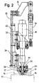
- Fig. 2 is a cross-section side view of the tacking station of Fig. 1;
- Fig. 3 is a view in cross-section made along line III-III of Fig. 1;
- Fig. 4 is a cross-section side view of a welding station for carrying out another step of the sealing method according to the invention; and
- Fig. 5 is a detail cross-section side view, on an enlarged scale, of the tip of a welding head used in the welding station of Fig. 4.
-
- According to the method of the invention, an alu-foil leaflet is tacked on a filling straw of a flexible bag by subjecting it to ultrasound vibration of a frequency and for a time duration such that the thermoplastic material of the straw and of the bottom layer of the alu-foil are only heated to a temperature of 50 to 60 °C, so that they become tacked to each other, though not fully fused together, and so that the nylon and polyester layers in the alu-foil are not affected. Because of the small amount of material involved in the partial melting or softening and of the low temperature attained, the material will quickly cool down to a temperature below the softening point of the thermoplastic material of the straw and of the bottom layer of the alu-foil, as soon as the ultrasound vibration is stopped. The flexible bag is then moved on to a final welding operation, where induction heating is used to heat the leaflet-straw junction to a high temperature, such as about 100 °C, for a sufficient time (such as 0.5 sec) to bring about a complete fusing of the junction.
- Because of the low temperature and short duration of the tacking operation, and because of the quick subsequent cooling, any nylon threads which have formed during punching will not soften and will quickly break off when the flexible bag is moved away from the tacking location. When the final fusing by induction heating is made, there can be no more nylon threads creating problems, irrespective of the temperature reached. Also, it will not be necessary to allow the sealed straw to cool down substantially before being moved on, so that the overall speed of the sealing operation can be increased.
- Preferably, according to the inventive method, a narrow edge of the sealing leaflet is bent down at about 30° to 60° around the straw tip during final welding. This will improve the sealing by extending the fusing area.
- The method is best carried out by providing an apparatus comprising a tacking station to carry out the punching and ultrasound tacking steps, and a welding station to carry out the final fusing by induction heating, placed at subsequent, adjacent locations along a processing line where the flexible bags are filled and sealed, say a conveyor belt or a turning table.
- With reference to Fig. 1, 2 and 3, showing a tacking station for carrying out the method of the invention, a
carrier plate 10, supported on the frame of a bag-filling apparatus not shown, carries abracket 12 having a vertical bore, lined with a polyester bushing 14, for receiving the upper end of afilling straw 16 of a bag 17 (shown in phantom lines). Straw 16 is one of a row of straws hanging from holding forks such as 15 (also shown in phantom lines), carried by a conveyor chain or turntable that is not shown, as it does not belong to the invention and is well known in the art. The carrier plate is movable vertically under the action of actuator means not shown to lowerbracket 12 onto astraw 16 so that the the straw tip is received into bushing 14. An alu-foil 18 is arranged for intermittent feeding along the upper surface ofbracket 12, above its bore, and apresser plate 20 which is further discussed below. The alu-foil supporting and feeding device is outside the scope of the invention, is well known in the art, and is therefore not shown. -
Carrier plate 10 also has avertical slideway 22 along which afirst slide 24 is movable under the driving action of anair cylinder 26. Abracket 28, bolted to slide 24, carries a roundhollow punch 30, preferably having a toothed cutting edge as known in the art.Presser plate 20 is elastically suspended fromslide 24, by means of bolts and springs such as 25. -
Punch 30 is aligned withbore 12, so that, whenslide 24 is lowered,punch 30 will move down to cut into alu-foil 18 and separate a leaflet 21 (Fig. 5) which will abut against the upper edge of the straw. - A
second slide 32 is movably supported onslideway 22. This is linked to the lower end of anair cylinder 34, depending from abracket 36, for vertical movement. Anultrasound sonotrode unit 38, known in the art, is carried byslide 32, is aligned withpunch 30 and has a narrow, concave-tippednose 40, adapted to be snugly received withinhollow punch 30 to be pressed against the upper edge ofstraw 16 or against any alu-foil leaflet lying on it. - When the tacking station as described above and shown in Figs. 1 to 3 is at rest, both
slides sonotrode 38 is well out of the way ofpunch 30 andpresser plate 20 is lifted from alu-foil 18, which can thus be fed one step (by means not shown) before starting the next tacking operation. - When the filling straw of a flexible bag is to be engaged by the tacking station, the carrier plate is lowered to receive the straw tip into bushing 14.
Slide 24 is then lowered so thatpresser plate 20 leans against alu-foil 18 (as shown on Fig. 1) to clamp it, and punch 30 then descends on it to cut a leaflet and push it onto the upper edge ofstraw 16. More or less simultaneously,slide 32 is also lowered, whilesonotrode 38 is turned on, so that itsnose 40 slides throughhollow punch 30 and presses onto leaflet to heat it by mechanical vibration. After the ultrasonic tacking has taken place, both the punch and the sonotrode are withdrawn, and finally the entire carrier plate is lifted back to free the straw and allow holdingfork 15 to move the bag forward to the next processing step. - The vibration frequency and the dwelling time of
sonotrode 38 are chosen so that the leaflet-straw junction is only moderately heated, typically to 50 to 60°C. This temperature is such that the leaflet is not fully welded, but only tacked to the straw tip, i.e., only partial fusing takes place. The vibration frequency is preferably about 30 kHz and the duration of sonotrode pressing is preferably about 1/10 sec. - The apparatus of the invention also comprises an induction welding station, where the tacked leaflet is fully welded to the filling straw. With reference to Fig. 4, the welding station comprises a
carrier plate 50, similar tocarrier plate 10, and also movable vertically under the action of actuator means not shown. Abracket 52, bolted tocarrier plate 50, carries ahousing 54 for aninduction coil 56.Coil 56 is held in position by a bushing 58, extending within the coil to confine it and to define an axial passage within it. Preferably,housing 54 and bushing 58 are made of a hard plastic material such as a polyester or other suitable synthetic material. Electric current is supplied tocoil 56, as known in the art, through acable 60, by apower unit 62, which is supported on anotherbracket 64 bolted to carrier plate 66. -
Bracket 52 also houses awelding head 68, which comprises a cylindrical bar of a synthetic material, received slidingly through a bore in the bracket and through bushing 48, and coaxial with it.Welding head 68 carries aweight 70 and aring nut 72 acting as a travel stop. - The above described welding station is located adjacent to the tacking station described above, so that
fork 15 will move the bag to the welding station after the bag has been treated in the tacking station.Carrier plate 50 is normally up, and is arranged to descend when the straw is aligned with the welding head, tu press the welding head onto the tacked leaflet. Current is then supplied for the required duration to fuse the leaflet on the straw, and the carrier plate is then lifted off, whilefork 15 carrying the bag may immediately move away from the welding station without waiting for the sealing junction to cool down. - In order to improve the seal, the lower end of welding
head 68, as shown on Fig. 5, is provided with apusher 69, of an elastomeric material such as a silicone, shaped with aperipheral rib 74, having an inclined inner side to define an axial, frusto-conical seat or depression having a cone angle of 30 to 60° to the axis of the welding head. The diameter of the rib is chosen to be slightly larger than the diameter of the bag-filling straw, so that, when the welding head is pressed down on the sealing leaflet, the frusto-conical depression will enclose and compress the leaflet against the edge of the straw also along its side, thus increasing the area of the weld and generally improving its reliability.
Claims (9)
- A method for sealing the polyethylene straw (16) of a flexible bag (17) with a leaflet of a compound sheet material having at least a bottom layer of readily meltable material, wherein the leaflet is punched out of a strip 18 of the sheet material, is laid onto the upper edge of the straw (16) with the bottom layer in contact therewith, and is fused therewith by local heating, characterized in that the fusing operation comprises the following steps:subjecting the straw (16) and the leaflet to ultrasonic vibration with a frequency and for a duration sufficient to increase the temperature of the upper edge of the straw and of the bottom layer of the leaflet so that they become tacked together, but insufficient to achieve permanent sealing and insufficient to achieve melting of any less readily meltable materials which are part of the leaflet;displacing the straw (16) and the tacked leaflet away from the punching location; andsubjecting the straw and the leaflet to induction heating while applying pressure to the leaflet, at a temperature and for a duration sufficient to achieve full sealing.
- The method of claim 1, characterized in that the readily meltable material of the bottom layer of the leaflet is polyethylene.
- The method of claim 1, characterized in that the readily meltable material of the bottom layer of the leaflet is polypropylene.
- The method of claim 1, characterized in that the vibration frequency of the sonotrode is about 30 kHz.
- The method of claim 4, characterized in that the time duration of sonotrode application to the leaflet is about 0.1 sec.
- An apparatus for sealing the thermoplastic straw (16) of a flexible bag (17) with a leaflet of a compound sheet material having at least a bottom layer of readily meltable material, having punching means (30) for punching the leaflet out of a strip (8) of the sheet material and for laying the leaflet onto the upper edge of the straw (16) with the bottom layer in contact therewith, characterized in that it further comprises:tacking means associated with the punching means and comprising an ultrasonic sonotrode unit (38, 40) arranged for pressing onto the leaflet lying on the straw (16) after it has been punched out by the punching means (30); andinduction welding means (68) located adjacent but separate from the tacking means; andmeans (15) for conveying a flexible bag from the tacking means to the welding means.
- The apparatus of claim 6, characterized in that the vibration frequency of the sonotrode unit is about 30 kHz.
- The apparatus of claim 6 or 7, characterized in that the welding means include a welding head (68) having an operating tip (69) provided with a frontal peripheral rib (74) to define a frontal depression.
- The apparatus of claim 8, characterized in that the rib on the welding head has an inclined inner side defining a frusto-conical surface with an angle of 30° to 60° to the axis of the welding head.
Priority Applications (3)
| Application Number | Priority Date | Filing Date | Title |
|---|---|---|---|
| ES99830205T ES2175920T3 (en) | 1999-04-08 | 1999-04-08 | METHOD AND APPLIANCE FOR SEALING FLEXIBLE BAG PADS. |
| EP99830205A EP1043146B1 (en) | 1999-04-08 | 1999-04-08 | Method and apparatus for sealing straws of flexible bags |
| DE69901931T DE69901931T2 (en) | 1999-04-08 | 1999-04-08 | Method and apparatus for sealing straws for flexible bags |
Applications Claiming Priority (1)
| Application Number | Priority Date | Filing Date | Title |
|---|---|---|---|
| EP99830205A EP1043146B1 (en) | 1999-04-08 | 1999-04-08 | Method and apparatus for sealing straws of flexible bags |
Publications (2)
| Publication Number | Publication Date |
|---|---|
| EP1043146A1 EP1043146A1 (en) | 2000-10-11 |
| EP1043146B1 true EP1043146B1 (en) | 2002-06-26 |
Family
ID=8243348
Family Applications (1)
| Application Number | Title | Priority Date | Filing Date |
|---|---|---|---|
| EP99830205A Expired - Lifetime EP1043146B1 (en) | 1999-04-08 | 1999-04-08 | Method and apparatus for sealing straws of flexible bags |
Country Status (3)
| Country | Link |
|---|---|
| EP (1) | EP1043146B1 (en) |
| DE (1) | DE69901931T2 (en) |
| ES (1) | ES2175920T3 (en) |
Families Citing this family (4)
| Publication number | Priority date | Publication date | Assignee | Title |
|---|---|---|---|---|
| GB0209316D0 (en) | 2002-04-24 | 2002-06-05 | Relco Uk Ltd | Cutting device |
| RU2465138C2 (en) * | 2010-12-27 | 2012-10-27 | Федеральное государственное бюджетное образовательное учреждение высшего профессионального образования "Ульяновский государственный технический университет" | Method of ultrasound welding of synthetic materials |
| WO2017015769A1 (en) | 2015-07-29 | 2017-02-02 | Woodwelding Ag | Method for joining a device to an object with the aid of ultrasonic vibration energy and device and installation suitable for the method |
| DE102016107958A1 (en) | 2016-04-28 | 2017-11-02 | Herrmann Ultraschalltechnik Gmbh & Co. Kg | Punching-sealing unit and ultrasonic processing device with such |
Family Cites Families (10)
| Publication number | Priority date | Publication date | Assignee | Title |
|---|---|---|---|---|
| US3549440A (en) * | 1967-10-26 | 1970-12-22 | United Glass Ltd | Method for sealing a membrane to the mouth of a container utilizing induced radio frequency current |
| GB1289298A (en) * | 1968-10-18 | 1972-09-13 | ||
| FR2511294B1 (en) * | 1981-08-12 | 1986-06-20 | Lyonnaise Bouchage | METHOD AND MACHINE FOR LAYING LIDS ON FLEXIBLE TUBES OF METALLIC OR NON-METALLIC PLASTIC MATERIAL |
| US4411720A (en) * | 1982-03-22 | 1983-10-25 | Branson Ultrasonics Corporation | Ultrasonic welding method for sealing a thermoplastic cap to the neck of a thermoplastic container |
| JPS59214616A (en) * | 1983-05-21 | 1984-12-04 | Toyo Alum Kk | Method of heat sealing |
| US4683016A (en) * | 1985-09-03 | 1987-07-28 | Sun Coast Plastics, Inc. | Process for forming a two part closure |
| US4719739A (en) * | 1986-09-16 | 1988-01-19 | Montreal Milling Cutter Company, Inc. | Continuous motion in-line sealer |
| JP2585587B2 (en) * | 1987-04-17 | 1997-02-26 | 株式会社吉野工業所 | Ultrasonic welding mold and ultrasonic welding method using the mold |
| US4938818A (en) * | 1988-12-29 | 1990-07-03 | Teledyne Industries, Inc. | Method of forming a seal |
| FR2678859B1 (en) * | 1991-07-10 | 1995-06-16 | Bouchon Rapid | METHOD OF WELDING A SEALING CAP ON A RECEIVING PART AND WELDING SONOTRODE USED IN SAID METHOD. |
-
1999
- 1999-04-08 ES ES99830205T patent/ES2175920T3/en not_active Expired - Lifetime
- 1999-04-08 EP EP99830205A patent/EP1043146B1/en not_active Expired - Lifetime
- 1999-04-08 DE DE69901931T patent/DE69901931T2/en not_active Expired - Fee Related
Also Published As
| Publication number | Publication date |
|---|---|
| EP1043146A1 (en) | 2000-10-11 |
| DE69901931D1 (en) | 2002-08-01 |
| ES2175920T3 (en) | 2002-11-16 |
| DE69901931T2 (en) | 2003-01-09 |
Similar Documents
| Publication | Publication Date | Title |
|---|---|---|
| US4534818A (en) | Method and apparatus for ultrasonic sealing | |
| US3069303A (en) | Process and apparatus for producing flexible containers | |
| CA1243530A (en) | Apparatus and method for attaching a fitment to a web of film | |
| US4630429A (en) | Apparatus and method for sealing a web of film in a form, fill, and seal packaging system | |
| US5247779A (en) | Self voiding jaw for packaging machine | |
| AU659362B1 (en) | Vertical-type filling and packaging machine | |
| US3815318A (en) | Packaging method and apparatus | |
| JPH11514941A (en) | Method and apparatus for attaching an article to a thermoplastic material | |
| US4035987A (en) | Apparatus for sealing the heads of containers | |
| US5032213A (en) | Thermal lid sealing method and apparatus | |
| NZ239048A (en) | Forming and filling flexible film pouches: sealed by ultrasonic energy | |
| US4981546A (en) | Heat-sealing device for thermoplastic films | |
| JPS62500995A (en) | container | |
| WO1995024341A1 (en) | Apparatus for sealing a container | |
| JPH0126928B2 (en) | ||
| US3748811A (en) | Packaging method and machine | |
| EP1043146B1 (en) | Method and apparatus for sealing straws of flexible bags | |
| US4131503A (en) | Method and apparatus for sealing and cutting thermoplastic material | |
| GB2120162A (en) | Apparatus for forming tubular plastics sleeves for application to containers | |
| US3531359A (en) | Apparatus for heat-sealing of plastic materials | |
| EP1507649B1 (en) | Process for the manufacture of a tube blank | |
| EP0597544B1 (en) | Apparatus for longitudinal welding with fast and reliable trimmed scrap removal | |
| US4809852A (en) | Disposable container | |
| JP2005206202A (en) | Packaging method and packaging device for tubular package | |
| JP2784698B2 (en) | Method and apparatus for manufacturing bottle packaging bag and packaging bottle |
Legal Events
| Date | Code | Title | Description |
|---|---|---|---|
| PUAI | Public reference made under article 153(3) epc to a published international application that has entered the european phase |
Free format text: ORIGINAL CODE: 0009012 |
|
| AK | Designated contracting states |
Kind code of ref document: A1 Designated state(s): CH DE ES FR GB IT LI NL SE |
|
| AX | Request for extension of the european patent |
Free format text: AL;LT;LV;MK;RO;SI |
|
| 17P | Request for examination filed |
Effective date: 20001024 |
|
| AKX | Designation fees paid |
Free format text: CH DE ES FR GB IT LI NL SE |
|
| GRAG | Despatch of communication of intention to grant |
Free format text: ORIGINAL CODE: EPIDOS AGRA |
|
| 17Q | First examination report despatched |
Effective date: 20011004 |
|
| GRAG | Despatch of communication of intention to grant |
Free format text: ORIGINAL CODE: EPIDOS AGRA |
|
| GRAH | Despatch of communication of intention to grant a patent |
Free format text: ORIGINAL CODE: EPIDOS IGRA |
|
| GRAH | Despatch of communication of intention to grant a patent |
Free format text: ORIGINAL CODE: EPIDOS IGRA |
|
| RAP1 | Party data changed (applicant data changed or rights of an application transferred) |
Owner name: ROBINO & GALANDRINO S.P.A. |
|
| GRAA | (expected) grant |
Free format text: ORIGINAL CODE: 0009210 |
|
| AK | Designated contracting states |
Kind code of ref document: B1 Designated state(s): CH DE ES FR GB IT LI NL SE |
|
| REG | Reference to a national code |
Ref country code: GB Ref legal event code: FG4D |
|
| REG | Reference to a national code |
Ref country code: CH Ref legal event code: EP |
|
| REG | Reference to a national code |
Ref country code: CH Ref legal event code: NV Representative=s name: PA ALDO ROEMPLER |
|
| REF | Corresponds to: |
Ref document number: 69901931 Country of ref document: DE Date of ref document: 20020801 |
|
| PG25 | Lapsed in a contracting state [announced via postgrant information from national office to epo] |
Ref country code: SE Free format text: LAPSE BECAUSE OF FAILURE TO SUBMIT A TRANSLATION OF THE DESCRIPTION OR TO PAY THE FEE WITHIN THE PRESCRIBED TIME-LIMIT Effective date: 20020926 |
|
| ET | Fr: translation filed | ||
| REG | Reference to a national code |
Ref country code: ES Ref legal event code: FG2A Ref document number: 2175920 Country of ref document: ES Kind code of ref document: T3 |
|
| PLBE | No opposition filed within time limit |
Free format text: ORIGINAL CODE: 0009261 |
|
| STAA | Information on the status of an ep patent application or granted ep patent |
Free format text: STATUS: NO OPPOSITION FILED WITHIN TIME LIMIT |
|
| 26N | No opposition filed |
Effective date: 20030327 |
|
| PGFP | Annual fee paid to national office [announced via postgrant information from national office to epo] |
Ref country code: ES Payment date: 20060411 Year of fee payment: 8 |
|
| PGFP | Annual fee paid to national office [announced via postgrant information from national office to epo] |
Ref country code: GB Payment date: 20060421 Year of fee payment: 8 Ref country code: FR Payment date: 20060421 Year of fee payment: 8 |
|
| PGFP | Annual fee paid to national office [announced via postgrant information from national office to epo] |
Ref country code: DE Payment date: 20060426 Year of fee payment: 8 |
|
| PGFP | Annual fee paid to national office [announced via postgrant information from national office to epo] |
Ref country code: NL Payment date: 20060430 Year of fee payment: 8 Ref country code: IT Payment date: 20060430 Year of fee payment: 8 |
|
| PGFP | Annual fee paid to national office [announced via postgrant information from national office to epo] |
Ref country code: CH Payment date: 20060704 Year of fee payment: 8 |
|
| REG | Reference to a national code |
Ref country code: CH Ref legal event code: PL |
|
| GBPC | Gb: european patent ceased through non-payment of renewal fee |
Effective date: 20070408 |
|
| NLV4 | Nl: lapsed or anulled due to non-payment of the annual fee |
Effective date: 20071101 |
|
| PG25 | Lapsed in a contracting state [announced via postgrant information from national office to epo] |
Ref country code: NL Free format text: LAPSE BECAUSE OF NON-PAYMENT OF DUE FEES Effective date: 20071101 Ref country code: DE Free format text: LAPSE BECAUSE OF NON-PAYMENT OF DUE FEES Effective date: 20071101 |
|
| PG25 | Lapsed in a contracting state [announced via postgrant information from national office to epo] |
Ref country code: CH Free format text: LAPSE BECAUSE OF NON-PAYMENT OF DUE FEES Effective date: 20070430 Ref country code: LI Free format text: LAPSE BECAUSE OF NON-PAYMENT OF DUE FEES Effective date: 20070430 |
|
| PG25 | Lapsed in a contracting state [announced via postgrant information from national office to epo] |
Ref country code: GB Free format text: LAPSE BECAUSE OF NON-PAYMENT OF DUE FEES Effective date: 20070408 |
|
| REG | Reference to a national code |
Ref country code: ES Ref legal event code: FD2A Effective date: 20070409 |
|
| PG25 | Lapsed in a contracting state [announced via postgrant information from national office to epo] |
Ref country code: FR Free format text: LAPSE BECAUSE OF NON-PAYMENT OF DUE FEES Effective date: 20070430 |
|
| PG25 | Lapsed in a contracting state [announced via postgrant information from national office to epo] |
Ref country code: ES Free format text: LAPSE BECAUSE OF NON-PAYMENT OF DUE FEES Effective date: 20070409 |
|
| PG25 | Lapsed in a contracting state [announced via postgrant information from national office to epo] |
Ref country code: IT Free format text: LAPSE BECAUSE OF NON-PAYMENT OF DUE FEES Effective date: 20070408 |