EP1043035A1 - Coating of membranes for medical devices - Google Patents
Coating of membranes for medical devices Download PDFInfo
- Publication number
- EP1043035A1 EP1043035A1 EP00302871A EP00302871A EP1043035A1 EP 1043035 A1 EP1043035 A1 EP 1043035A1 EP 00302871 A EP00302871 A EP 00302871A EP 00302871 A EP00302871 A EP 00302871A EP 1043035 A1 EP1043035 A1 EP 1043035A1
- Authority
- EP
- European Patent Office
- Prior art keywords
- blood
- coating
- fibres
- copolymer
- membrane
- Prior art date
- Legal status (The legal status is an assumption and is not a legal conclusion. Google has not performed a legal analysis and makes no representation as to the accuracy of the status listed.)
- Granted
Links
Images





Classifications
-
- B—PERFORMING OPERATIONS; TRANSPORTING
- B01—PHYSICAL OR CHEMICAL PROCESSES OR APPARATUS IN GENERAL
- B01D—SEPARATION
- B01D67/00—Processes specially adapted for manufacturing semi-permeable membranes for separation processes or apparatus
- B01D67/0081—After-treatment of organic or inorganic membranes
- B01D67/0088—Physical treatment with compounds, e.g. swelling, coating or impregnation
-
- A—HUMAN NECESSITIES
- A61—MEDICAL OR VETERINARY SCIENCE; HYGIENE
- A61L—METHODS OR APPARATUS FOR STERILISING MATERIALS OR OBJECTS IN GENERAL; DISINFECTION, STERILISATION OR DEODORISATION OF AIR; CHEMICAL ASPECTS OF BANDAGES, DRESSINGS, ABSORBENT PADS OR SURGICAL ARTICLES; MATERIALS FOR BANDAGES, DRESSINGS, ABSORBENT PADS OR SURGICAL ARTICLES
- A61L33/00—Antithrombogenic treatment of surgical articles, e.g. sutures, catheters, prostheses, or of articles for the manipulation or conditioning of blood; Materials for such treatment
- A61L33/06—Use of macromolecular materials
- A61L33/068—Use of macromolecular materials obtained otherwise than by reactions only involving carbon-to-carbon unsaturated bonds
-
- B—PERFORMING OPERATIONS; TRANSPORTING
- B01—PHYSICAL OR CHEMICAL PROCESSES OR APPARATUS IN GENERAL
- B01D—SEPARATION
- B01D63/00—Apparatus in general for separation processes using semi-permeable membranes
- B01D63/02—Hollow fibre modules
- B01D63/021—Manufacturing thereof
- B01D63/0233—Manufacturing thereof forming the bundle
-
- B—PERFORMING OPERATIONS; TRANSPORTING
- B01—PHYSICAL OR CHEMICAL PROCESSES OR APPARATUS IN GENERAL
- B01D—SEPARATION
- B01D71/00—Semi-permeable membranes for separation processes or apparatus characterised by the material; Manufacturing processes specially adapted therefor
- B01D71/06—Organic material
- B01D71/70—Polymers having silicon in the main chain, with or without sulfur, nitrogen, oxygen or carbon only
- B01D71/701—Polydimethylsiloxane
-
- B—PERFORMING OPERATIONS; TRANSPORTING
- B01—PHYSICAL OR CHEMICAL PROCESSES OR APPARATUS IN GENERAL
- B01D—SEPARATION
- B01D71/00—Semi-permeable membranes for separation processes or apparatus characterised by the material; Manufacturing processes specially adapted therefor
- B01D71/06—Organic material
- B01D71/76—Macromolecular material not specifically provided for in a single one of groups B01D71/08 - B01D71/74
-
- Y—GENERAL TAGGING OF NEW TECHNOLOGICAL DEVELOPMENTS; GENERAL TAGGING OF CROSS-SECTIONAL TECHNOLOGIES SPANNING OVER SEVERAL SECTIONS OF THE IPC; TECHNICAL SUBJECTS COVERED BY FORMER USPC CROSS-REFERENCE ART COLLECTIONS [XRACs] AND DIGESTS
- Y10—TECHNICAL SUBJECTS COVERED BY FORMER USPC
- Y10S—TECHNICAL SUBJECTS COVERED BY FORMER USPC CROSS-REFERENCE ART COLLECTIONS [XRACs] AND DIGESTS
- Y10S261/00—Gas and liquid contact apparatus
- Y10S261/28—Blood oxygenators
Definitions
- This invention relates to medical devices, such as polyvinylchloride (PVC) tubing and oxygenators that use hollow fibre membranes to replace carbon dioxide in the blood with oxygen.
- PVC polyvinylchloride
- the invention relates to an alkoxysilane/alkylsilane copolymer coating capable of reducing the migration of plasma across micropores in such membranes.
- Microporous hollow fibre membrane oxygenators are commonly used to support patients during heart bypass procedures such as cardiac artery bypass grafting (CABG), heart valve repair and replacement, and the like. Such oxygenators are designed to direct blood flow over (or through) the microporous hollow fibres while oxygen-rich gas flows through (or over) the fibre lumens. This results in simultaneous mass transfer of molecular oxygen and carbon dioxide in opposite directions across the membrane.
- CABG cardiac artery bypass grafting
- the efficiency of the device can be described by the gas transfer per unit area of membrane at a given blood flow rate, gas flow rate, and composition (i.e. the specific gas transfer rate, typically cm 3 of gas per litres of blood flow per minute per square metre of gas transfer area).
- micropores in the microporous hollow fibres are small enough to prevent whole-blood components such as platelets and red cells from passing through to the gas side of the membrane.
- materials used to manufacture the fibre are not primarily designed for blood compatibility. Both platelets and leukocytes adhere in great numbers to the materials, leading to significant activation of deleterious responses in the blood.
- heparin is known to have good blood compatibility properties and has been used as a coating on several commercialized products.
- heparin-based coatings are inherently expensive and complex due to the use of sodium heparin, a complex, costly and fragile biologically derived substance.
- the Carmeda Bioactive Surface (Medtronic, Inc.) uses a polymer primer coat followed by covalent attachment of heparin to primary amino groups present in the primer coat.
- the Duraflo Bonded Heparin Surface (Baxter, Inc.) uses a heparin-polymer blend-based coating that is intended to achieve similar results.
- Other heparin-based coatings intended to improve blood compatibility are available from other medical device manufacturers (Terumo, Jostra, 3M Sarns, etc.).
- Silicone polydimethyl siloxane-based resins
- a process commercialized by Cobe Laboratories, Inc. uses a block copolymer polymer additive/coating that is intended to decrease platelet and leukocyte adhesion/activation.
- plasma fluid component of blood
- plasma breakthrough a problem known as plasma migration or plasma breakthrough.
- plasma migration In the case of a design in which the blood flows over the fibres and the oxygen-rich gas flows within the fibre lumens, this migration will eventually render the device inoperable by filing the lumens with liquid that impedes gas flow.
- microporous hollow fibre membrane Another approach to improving plasma breakthrough performance is to modify the microporous hollow fibre membrane. Previous coating methods have attempted to close off the pores with a thin film of silicon resin, mechanically preventing fluid migration. Specific gas transfer rates are improved compared to silicon membrane oxygenators, but are still well below the rates found in uncoated microporous hollow fibre membrane devices.
- CVD chemical vapour deposition
- Biocompatibles, Inc. has a process for applying a phosphatidyl choline-methacrylate/butyl methacrylate copolymer that is intended to improve blood compatibility.
- BioInteractions, Inc. has a hydrogel/heparin mixture that is also intended to improve blood compatibility of blood oxygenators.
- the invention thus provides a medical device comprising a microporous hollow fibre membrane having a plurality of micropores, in which the membrane is provided with a coating comprising an alkoxysilane/alkylsilane copolymer.
- the membrane is coated with an alkoxysilane/alkylsilane copolymer to an extent sufficient to reduce migration of plasma across micropores in the membrane.
- the invention provides a method of coating a device comprising a microporous hollow fibre membrane, said method comprising the steps of:
- the device may be polyvinylchloride (PVC) tubing, any device comprising microporous hollow fibre membranes (such as blood oxygenators), or any other medical device which is prone to the plasma migration or plasma breakthrough problem.
- PVC polyvinylchloride
- the coating compound of the invention comprises alkoxysilane/alkylsilane copolymers, preferably aminoalkylsiloxane, and most preferably the aminoalkylsiloxane commercially available from Dow Corning under the designation MDX4-4159 (see, for example, http://www.factor2.com/a-4159.htm).
- One of the key aspects of the invention is that it uses a siloxane material that cures in-place under very mild conditions. This is due to the use of an alkoxysilane/alkylsilane copolymer as mentioned above.
- the material cures via cross-linking of the alkoxysilane groups with each other, which occurs at room temperature in the presence of a trace amount of water as catalyst.
- the method of coating the medical device creates a thin film of silicone on the device (including the microporous fibres of the device), but does not cover or fill the micropores with the thin film.
- the improved resistance to plasma breakthrough i.e. increased time to device failure
- the prepolymer is applied as a thin film via solvent; after the solvent carrier evaporates away, the prepolymer cures to a soft resin layer completely covering the treated surface. All blood contact occurs with the silicon resin rather than with the underlying material.
- the result is a device with significantly greater time to failure for plasma breakthrough with specific gas transfer rates almost unchanged compared to identical uncoated devices.
- the process is also economically attractive, easier to implement, avoids toxic reagents, and can be used with a wider variety of finished products.
- oxygenators employing microporous hollow fibre membranes for blood/gas exchange include the AFFINITY brand and MAXIMA FORTÉ brand oxygenators available from Medtronic Perfusion Systems, Medtronic, Inc. of Minneapolis, Minnesota, USA (see US Patents Re. 36,125, 5,462,619, and 5,346,621 for the AFFINITY brand oxygenator; and US Patents 5,858,233, 5,823,987, 5,762,875, and 5,718,871 for the MAXIMA FORTÉ brand oxygenator).
- Dow Corning MDX4-4159 Fluid 50% Medical Grade Dispersion is a liquid RTV solution containing 50 percent active silicone ingredients in mixed aliphatic and isopropanol solvents.
- the active silicone used is an aminofunctional dimethylsiloxane copolymer.
- the polar nature of the aminofunctional groups and the ability of the fluid to cure cause films to deposit and adhere to metal cutting edges, such as razor blades.
- the primary known use of MDX4-4159 is dipping, coating and spraying devices to create a thin layer of silicone for lubrication.
- alkoxysilane/alkylsilane copolymer coating for use in the invention is a random or block copolymer of the form: (in which
- a preferred embodiment of the invention may be illustrated by considering the design of the MAXIMA FORTÉ oxygenator available from Medtronic Perfusion Systems, Medtronic, Inc., Minneapolis, Minnesota, USA. Of course, details described below that are specific to this device, but not necessary to practice of the invention, may be different in other embodiments of the invention.
- a blood oxygenator 10 comprises an outer generally cylindrical vessel 12, which is sealed at its upper end by a generally saucer-shaped upper hollow venous gas header 14.
- a generally saucer-shaped lower hollow venous gas header 16 seals the lower end of the vessel 12.
- a blood inlet manifold 18 is connected to the centre of the underside of the lower venous gas header 16.
- Concentric, generally cylindrical inner and outer heat exchanger housings 20 and 22 are connected at their lower ends to the centre of the lower venous header 16.
- the upper end of the outer heat exchanger housing 22 includes a transition manifold 24.
- the interior of the inner heat exchanger housing 20 surrounds and encloses a generally cylindrical first fibre bundle 26 made up of a plurality of vertically oriented hollow micro-conduits.
- a second generally cylindrical fibre bundle 28 concentrically surrounds the outer heat exchanger housing 22 and is positioned inside the inner wall of the cylindrical vessel 12.
- the upper and lower ends of the generally ring-shaped second fibre bundle 28 interact with the upper and lower venous gas headers 14 and 16, respectively.
- the blood inlet manifold 18 ( Figure 3) includes a barbed blood inlet nozzle 30 which bends downwardly at an angle relative to the central vertical axis of the vessel 12.
- a barbed blood outlet nozzle 32 ( Figures 3 and 4) extends horizontally from the exterior of an enlarged or flared portion 12a of the vessel 12.
- a standard Leur fitting 34 ( Figure 3) extends vertically from the base of the blood outlet nozzle 32.
- a thermometer probe fitting 36 ( Figure 4) extends horizontally from the base of the blood outlet nozzle 32.
- Inlet and outlet nozzles 38 and 40 for a heat transfer fluid such as water extend horizontally from one side of the low venous gas header 16 and communicate with water flow passages inside the inner heat exchanger housing 20.
- a barbed de-bubbler nozzle 42 ( Figure 3) extends upwardly at an angle from the flared portion 12a of the vessel 12.
- a gas mixture inlet nozzle 44 ( Figures 2, 3 and 4) extends horizontally from the periphery of the upper venous gas header 14.
- a gas mixture outlet nozzle 46 ( Figures 2 and 4) extends from the periphery of the lower venous gas header 16 parallel to the water inlet and outlet nozzles 38 and 40.
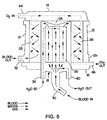
- the blood, heat transfer fluid and gas mixture flow paths of the blood oxygenator 10 can best be understood by way of reference to the diagrammatic vertical sectional view of Figure 5.
- the flow of blood is illustrated diagrammatically by the hold solid arrows.
- the dashed lines illustrate the flow of heat transfer fluid (water).
- the flow of gas mixture is illustrated by the sequence of dots.
- Blood from the patient flows through tubing (not illustrated) connected to the blood inlet nozzle 30. This incoming blood spreads out through the blood inlet manifold 18 and travels vertically through the micro-conduits of the first fibre bundle 26 of the central heat exchanger that forms the core of the blood oxygenator 10. Water flows in through the inlet nozzle 38 vertically to the top of the heat exchanger fibre bundle 26 through a separate channel isolated from the fibre bundle 26.
- the water is then directed down and across the outside of the micro-conduits of the fibre bundle 26.
- the water flows around the outside of the micro-conduits opposite the flow of the blood within the micro-conduits.
- the water exiting from the lower end of the first fibre bundle 26 exits through the outlet nozzle 40.
- the water is heated or cooled outside the blood oxygenator, as necessary to regulate the temperature of the blood flowing through the micro-conduits of the heat exchanger.
- the use of a counter-flow heat exchanger provides optimum heat exchange efficiency.
- the counter-flow design is not essential to the invention.
- the temperature of the blood can be monitored by a circuit (not illustrated) that includes a thermistor or other temperature sensing device (not illustrated) mounted inside the thermometer probe fitting 36 ( Figures 3 and 4).
- the thermometer probe fitting 36 is a preferred location for connection of an electrical bridge to the blood side of the heat exchanger, since the temperature sensing device is likely to be coincidentally an electrically conductive material (typically metal) already in physical contact with the blood.
- the invention may be implemented by connecting a conductive bridge between the temperature sensing device and any convenient location on the other side of the heat exchanger.
- Blood exiting from the upper end of the first fibre bundle 26 ( Figure 5) of the heat exchanger is directed radially outwardly by the transition manifold 24. This blood then travels around the outside of the fibres of the second fibre bundle 28 that forms the oxygenator. The blood travels downwardly past the outside surfaces of the fibres of the second fibre bundle 28. When the blood reaches the lower portion of the second fibre bundle 28, it is collected in an outlet manifold defined by the flared portion 12a of the vessel and exits through the blood outlet nozzle 32.
- the blood outlet nozzle 32 is connected to tubing (not illustrated) for returning the blood to the patient.
- a gas mixture rich in oxygen from a pressurized source (not illustrated) is conveyed through a hose (not illustrated), through the gas mixture inlet nozzle 44, and into the upper venous gas header 14.
- the upper gas header 14 communicates with the upper ends of the fibres in the second fibre bundle 28 forming the membrane oxygenator.
- the oxygen-rich gas mixture travels down through the interior of the fibres in the fibre bundle 28. These fibres are micro-porous. Carbon dioxide from the blood surrounding the fibres in the bundle 28 diffuses through the walls of the fibres into the gas mixture. Similarly, oxygen from the gas mixture inside the fibres of the bundle 28 diffuses through the micro-pores into the blood.
- the gas mixture now having an elevated carbon dioxide content exits the lower ends of the fibres of the second fibre bundle 28 into the lower venous gas header 16 and then exits therefrom via the gas mixture outlet nozzle 46.
- This gas mixture now has a lower oxygen content.
- the nozzle 46 is connected to another gas hose (not illustrated).
- FIG. 7 is a diagrammatic illustration of the first fibre bundle 26 which serves as the core of the heat exchanger portion of the blood oxygenator 10.
- the fibre bundle 26 has a generally cylindrical configuration and comprises approximately 5,400 vertically (axially) extending hollow fibres 50.
- the fibres are provided as a continuous long web of micro-conduit wrapping material in which the fibres are held together by a thin, flexible, horizontally extending woven interconnect.
- Such wrapping material is commercially available from Mitsubishi Rayon, Co., Ltd. under the designation HFE430-1 Hollow Fibre. This material uses polyethylene fibres.
- Similar wrapping material is also commercially available from Hoechst Celanese Corporation under the designation Heat Exchanger Fibre Mat. This material uses polypropylene fibres.
- the micro-conduit wrapping material of the heat exchanger core is wound about a central, vertically orientated elongated spindle 52 (Figure 8).
- the spindle 52 has an intermediate segment 54 having a cross-shaped cross-section, as best seen in Figure 9.
- the spindle 52 has enlarged driving ends 56 connected to the opposite ends of the intermediate segment 54.
- Each of the driving ends 56 has a pair of parallel extending ribs 58 ( Figure 10) which are used to lock the spindle into a winding machine (not illustrated). This machine is utilized to wind the micro-conduit wrapping material about the spindle 52.
- the micro-conduit wrapping material is compactly wound about the central spindle 52, but without any substantial tension on the web.
- the micro-conduit may be provided in a heat exchanger micro-conduit wrapping material.
- the wrapping material comprises micro-conduit fibres attached to a thin flexible interconnect, such as woven netting, to maintain the fibres at predetermined spacings in substantially parallel alignment with each other.
- the wrapping material is wrapped about an elongated spindle having first and second ends, such that the ends of each fibre reside proximate the spindle's first and second ends. After the ends of the fibres are trimmed as needed, a shell is placed around the wrapping material and spindle. Opposing first and second seals are created by applying potting compound between fibres proximate the spindle's first end and proximate the spindle's second end.
- the heat exchanger micro-conduit for short, preferably comprises a plurality of small fibres 100, as shown in Figure 11.
- the fibres 100 are arranged in a "mat" of micro-conduit wrapping material 102, which is described in greater detail below.
- Each fibre 100 comprises an elongated two-ended fibre.
- Each fibre 100 is hollow, with a cross-sectional shape preferably being rounded, or alternatively triangular, rectangular, or another appropriate shape. Since the fibres 100 are hollow, each fibre 100 defines an inner channel 150 having an inner surface 152, as shown in Figure 12.
- the outer diameter of the fibre is about 475 ⁇ m while the diameter of the inner channel 150 is about 428 ⁇ m.
- inner and outer diameters may be used, depending upon the requirements of the particular application.
- the difference between the inner and outer diameters is preferably small, to encourage heat exchange through the fibres' walls.
- the fibres 100 may be about 10 cm long, for example. However, a wide range of fibre lengths may be used, depending upon the requirements of the particular application.
- the fibres 100 may be made from a plastic material such as polypropylene, polyethylene, a different polymeric substance, or another material that is inexpensive, pharmacologically safe, lightweight, easily cut, and flexible.
- the material of the fibres 100 must also be easily formed into fibres with sufficiently small inner and outer dimensions.
- the fibres 100 would be made of a hydrophilic material, however, micro-conduit made of such material is not presently commercially available.
- Figure 11 illustrates a section of micro-conduit wrapping material 102.
- the material 102 includes a thin flexible interconnect 104 that maintains the fibres 100 at predetermined spacings in substantially parallel alignment with each other.
- the interconnect comprises substantially parallel lengths of flexible thread that are woven or kartted to hold the fibres about 0.5 mm apart, generally parallel to each other.
- the wrapping material 102 aids in positioning the fibres 100 during construction of a blood heat exchanger, as discussed below.
- the mat or wrapping material 102 may be made of commercially available product from Mitsubishi Rayon Co., Ltd. sold under the designation HFE 430-1 Hollow Fibre, which uses polyethylene fibres. Similar wrapping material is also commercially available from Hoechst Celanese Corp. under the designation Heat Exchanger Fibre Mat, which uses polypropylene fibres.
- the micro-conduit wrapping material 102 is wrapped about the spindle, the fibres are installed into the shell, and the upper and lower seals are formed by injecting potting compound between the fibres 100 near the upper and lower surfaces of the core. Sufficient potting compound is applied to substantially seal the spaces between the fibres. Then, the fibres 100 are trimmed near each end of the spindle. Preferably, the trimmed fibres 100 form uniform flat upper and lower surfaces of the core. With the seals in place, liquids such as aqueous priming solution and blood may be directed into the fibres 100 through their ends, without leaking any liquid into the spaces between the fibres. Finally, the manifolds are attached to the shell. Also, hoses and other plumbing lines are attached to the heat exchanger 300 as needed, for transportation of heat exchange medium, blood, priming solution, oxygen, and other media as appropriate.
- the heat exchanger regulates the temperature of a patient's blood during a medical procedure such as open heart surgery. Due to the large number of fibres 100 and the small size of the fibres, there is a substantial area of surface contact between the heat exchange medium and the contents of the fibres 100. The temperature of blood flowing through the core is efficiently regulated, due to the high degree of contact between the blood and the heat exchange medium.
- the configuration of the lower venous gas header 16, the inner heat exchanger housing 20, the water inlet and outlet nozzles 38 and 40 and the gas mixture outlet nozzle 46, are illustrated in Figures 13-17. These parts, along with the raised annular wall member 68 that receives the blood inlet manifold 18, are all injection molded as a single unitary piece of plastic.
- the inner heat exchanger housing 20 is formed with an interior vertical wall member 76 ( Figure 15) that defines a water flow channel or path 78 ( Figures 13 and 15) which extends vertically along one side of the heat exchanger housing 20.
- the lower end of the water flow path 78 communicates with the interior of the water inlet nozzle 38.
- the upper end of the water flow path 78 communicates through a port 80 ( Figure 15) into the upper interior of the housing 20. This permits the incoming heat exchange water to be disbursed around the upper ends of the thousands of micro-conduits or fibres 50 of the heat exchanger fibre bundle 26. As previously explained, this water flows down around the outside of the fibres 50, through another port 82, and then out through water outlet nozzle 40. The opening of the nozzle 40 is shown at 84 in Figure 15.
- the upper end of the cylindrical heat exchanger housing 20 is molded with a fitting ring 86 (Figures 15 and 17) having an upwardly opening circular recess 88 ( Figure 18) for receiving, and interfitting with, a downwardly extending circular flange of the outer heat exchanger housing 22.
- the fitting ring 86 is connected to the main part of the housing 20 by small plastic extensions 91 ( Figure 17).
- the remainder of the structures illustrated and described herein are preferably injection molded of clear polycarbonate plastic.
- Suitable plastics are commercially available from Bayer under the designation MAKROLON and from General Electric under the designation LEXAN HP2R-1112.
- the separately molded plastic components may be assembled and permanently affixed to each other with a suitable non-toxic ultraviolet (UV) curable adhesive.
- This protocol covers siloxane coating of PVC tubing, oxygenators (using the Medtronic Maxima Forté as a non-limiting example), and other medical devices.
- the required process equipment includes: adequately vented fume hood; roller or centrifugal pump capable of pumping a minimum of 2 litres/minute; Lindberg/Blue M constant temperature water bath or equivalent; stir-plate (Bibby B212 or equivalent); stir bars; 4000 ml to 6000 ml glass flasks; Viton brand tubing; balance (Mettler 4000 or equivalent); pH metre; 2000 ml to 6000 ml glass volumetric flasks; 500 ml to 2000 ml graduated cylinders; polypropylene and glass funnels; polypropylene and glass containers; aluminum foil; lint-free paper towels; and PVC tubing or equivalent.
- the required process materials are: hexanes (ACS Reagent Grade); deionized water (“DI”); Dow Corning MDX4-4159 fluid; 0.1-N Glacial acetic acid; isopropyl alcohol (“IPA”); and 1.0 N hydrochloric acid.
- Safety glasses and protective gloves should be worn at all times. All operations should be performed in a well vented fume hood. All waste chemicals/solvents should be disposed in appropriate waste containers.
- Stock solutions (defined as solutions that have a defined shelf-life which allows preparation before initiating the actual process) should be prepared as follows.
- IPA premix Preparation of IPA premix: combine 75.0 g (74.6 wt %) of IPA, 25.0 g (24.9 wt %) of DI, and 0.5 g (00.5 wt %) of 1.0 N HCl. The solution should be covered immediately and allowed to stir for a minimum of 5 minutes. The IPA premix should be stored at ambient temperature in a tightly closed container free from moisture.
- ZX solids solution may be performed according to either of two options.
- a 3 wt % mixture of ZX solids solution in hexane is formed by combining 1880.0 g (94 wt %) of hexane and 120.0 g (6 wt %) of MDX4-4159.
- a 1.5 wt % ZX solids solution in a IPA/hexane mixture is formed by combining 1580.0 g (79 wt %) of IPA, 360.0 g (18 wt %) of hexane, and 60.0 g (3 wt %) of MDX4-4159.
- Mixing of the IPA premix and ZX solids solution may also be performed according to either of two options.
- mixing of the IPA premix and 3 wt % ZX solids in hexane is performed by combining 2000.0 g (99 wt %) of 3 wt % ZX solids solution and 20.0 g (1 wt %) of IPA premix.
- mixing of the IPA premix and 1.5 wt % ZX solids in IPA/hexane is performed by combining 2000.0 g (99.5 wt %) of 1.5 wt % ZX solids solution and 10.0 g (0.5 wt %) of IPA premix.
- the solution should be covered immediately and allowed to stir for a minimum of 5 minutes.
- the ZX solution should be stored at ambient temperature in a tightly closed container free from moisture.
- the ZX coating procedure for PVC tubing involves dipping the tubing in the container of ZX solution for 2 minutes and then removing the tubing from the solution. Removal of excess coating from PVC tubing is performed by allowing excess ZX solution to gravity drain for 1 minute. Then, supply 3 PSI (21 kPa, 5-6 SCFM) for 2 minutes, followed by 10 PSI (69 kPa, 7-8 SCFM) for 10 minutes. Curing of the ZX coating on the PVC tubing is performed with humid air (50 ⁇ 5 % relative humidity) at less than 3 PSI (21 kPa) for 30 minutes, followed by 60 minutes of 5-8 PSI (34-55 kPa) of dry air (0 % relative humidity).
- microporous hollow fibre membrane oxygenators may be illustrated with the following procedure, which uses, as an example only, the Medtronic MAXIMA FORTÉ brand oxygenator.
- the procedure is easily adapted to other oxygenators using microporous hollow fibre membranes, such as the Medtronic AFFINITY brand oxygenator, according to principles known in the art.
- the curing procedure involves using humid air (50 ⁇ 5 % relative humidity) at less than 3 PSI (21 kPa) for 30 minutes and then 5-8 PSI (34-55 kPa) of dry air (0 % relative humidity) for 60 minutes.
- the success of the invention may be demonstrated by considering the following data. Twelve identical Medtronic MAXIMA FORTÉ brand oxygenators were tested for plasma breakthrough under identical conditions. The oxygenators were considered and tested in six pairs. One member of each pair of oxygenators was coated with aminoalkylsiloxane compound according to the protocol described above. The other member was uncoated. The test measured the time in hours for confirmed plasma breakthrough.
- Test Devices Control Devices Identifier Time (hours) Identifier Time (hours) T1 97324804 72 C1 29 T1 97324483 34 C2 26 T1 97324458 74 C3 25 T1 97324474 54 C4 14 T1 97324467 36 C5 22 T1 97324753 54 C6 23 Mean 54 Mean 23 Standard 16 Standard 5 Deviation Deviation
- the tests of units T2 and T5 were terminated after 34 and 36 hours, respectively, because of excessive inlet pressure (>1000 mm Hg, >1.3 x 10 5 Pa) buildup. This type of pressure increase is common due to the aging of the test fluid (bovine blood) during the study and is not reflective of the performance of the coating.
- the test of unit C4 was terminated after 14 hours after the microporous fibre developed a leak, which interfered with effluent specific gravity measurements.
Landscapes
- Chemical & Material Sciences (AREA)
- Chemical Kinetics & Catalysis (AREA)
- Health & Medical Sciences (AREA)
- Engineering & Computer Science (AREA)
- Manufacturing & Machinery (AREA)
- Surgery (AREA)
- Materials Engineering (AREA)
- Hematology (AREA)
- Inorganic Chemistry (AREA)
- Epidemiology (AREA)
- Life Sciences & Earth Sciences (AREA)
- Animal Behavior & Ethology (AREA)
- General Health & Medical Sciences (AREA)
- Public Health (AREA)
- Veterinary Medicine (AREA)
- External Artificial Organs (AREA)
- Separation Using Semi-Permeable Membranes (AREA)
- Materials For Medical Uses (AREA)
Abstract
Description
- This invention relates to medical devices, such as polyvinylchloride (PVC) tubing and oxygenators that use hollow fibre membranes to replace carbon dioxide in the blood with oxygen. In particular, the invention relates to an alkoxysilane/alkylsilane copolymer coating capable of reducing the migration of plasma across micropores in such membranes.
- Microporous hollow fibre membrane oxygenators are commonly used to support patients during heart bypass procedures such as cardiac artery bypass grafting (CABG), heart valve repair and replacement, and the like. Such oxygenators are designed to direct blood flow over (or through) the microporous hollow fibres while oxygen-rich gas flows through (or over) the fibre lumens. This results in simultaneous mass transfer of molecular oxygen and carbon dioxide in opposite directions across the membrane.
- The efficiency of the device can be described by the gas transfer per unit area of membrane at a given blood flow rate, gas flow rate, and composition (i.e. the specific gas transfer rate, typically cm3 of gas per litres of blood flow per minute per square metre of gas transfer area).
- The micropores in the microporous hollow fibres are small enough to prevent whole-blood components such as platelets and red cells from passing through to the gas side of the membrane. However, the materials used to manufacture the fibre (polypropylenes, polyethylenes) are not primarily designed for blood compatibility. Both platelets and leukocytes adhere in great numbers to the materials, leading to significant activation of deleterious responses in the blood.
- Several coating methods have been used to improve blood compatibility by providing an additional layer or "second skin" for the underlying structural material comprising the fibre membrane. The added layer of material provides a blood-surface interaction superior to that seen for the bulk fibre materials. For example, heparin is known to have good blood compatibility properties and has been used as a coating on several commercialized products. Unfortunately, heparin-based coatings are inherently expensive and complex due to the use of sodium heparin, a complex, costly and fragile biologically derived substance.
- The Carmeda Bioactive Surface (Medtronic, Inc.) uses a polymer primer coat followed by covalent attachment of heparin to primary amino groups present in the primer coat. The Duraflo Bonded Heparin Surface (Baxter, Inc.) uses a heparin-polymer blend-based coating that is intended to achieve similar results. Other heparin-based coatings intended to improve blood compatibility are available from other medical device manufacturers (Terumo, Jostra, 3M Sarns, etc.).
- Silicone (polydimethyl siloxane-based resins) is known to be compatible with blood. A process commercialized by Cobe Laboratories, Inc. uses a block copolymer polymer additive/coating that is intended to decrease platelet and leukocyte adhesion/activation.
- Another problem is that, over time, the fluid component of blood (plasma) can migrate through the pores, a problem known as plasma migration or plasma breakthrough. In the case of a design in which the blood flows over the fibres and the oxygen-rich gas flows within the fibre lumens, this migration will eventually render the device inoperable by filing the lumens with liquid that impedes gas flow.
- Reducing the average pore size can increase the time to failure somewhat. This is the approach taken in a fibre commercially available from Hoescht-Celanese and known under the tradename of Plasma Resistant Fibre or PRF. Further improvement is desirable.
- One approach to the problem has been to use non-porous silicone membrane oxygenation systems. While no plasma can migrate through the membrane, gas transfer is very poor compared to that of microporous hollow fibre membrane oxygenators due to gas diffusion limitations through the solid polymer material.
- Another approach to improving plasma breakthrough performance is to modify the microporous hollow fibre membrane. Previous coating methods have attempted to close off the pores with a thin film of silicon resin, mechanically preventing fluid migration. Specific gas transfer rates are improved compared to silicon membrane oxygenators, but are still well below the rates found in uncoated microporous hollow fibre membrane devices.
- Another approach is the use of chemical vapour deposition (CVD) to deposit various coatings such as silicone resins on devices (e.g. Thoratec, InnerDyne). This approach suffers from poor specific gas transfer and also uses costly, toxic reagents. In addition, the CVD method is difficult to apply to the internal surfaces of finished products.
- Biocompatibles, Inc. has a process for applying a phosphatidyl choline-methacrylate/butyl methacrylate copolymer that is intended to improve blood compatibility. BioInteractions, Inc. has a hydrogel/heparin mixture that is also intended to improve blood compatibility of blood oxygenators.
- A need exists for alternative methods of preventing plasma breakthrough in medical devices, such as PVC tubing and oxygenators, which use hollow fibre membranes to replace carbon dioxide in the blood with oxygen. Surprisingly, the applicants have found that this need can be met by the use of a coating comprising an alkoxysilane/alkylsilane copolymer.
- Viewed from one aspect the invention thus provides a medical device comprising a microporous hollow fibre membrane having a plurality of micropores, in which the membrane is provided with a coating comprising an alkoxysilane/alkylsilane copolymer. Preferably, the membrane is coated with an alkoxysilane/alkylsilane copolymer to an extent sufficient to reduce migration of plasma across micropores in the membrane.
- Viewed from a further aspect the invention provides a method of coating a device comprising a microporous hollow fibre membrane, said method comprising the steps of:
- (a) formulating a coating solution comprising an alkoxysilane/alkylsilane copolymer;
- (b) contacting said device with the coating solution whereby to form a film of silicone on said membrane; and
- (c) curing the copolymer on the device.
-
- The device may be polyvinylchloride (PVC) tubing, any device comprising microporous hollow fibre membranes (such as blood oxygenators), or any other medical device which is prone to the plasma migration or plasma breakthrough problem.
- The coating compound of the invention comprises alkoxysilane/alkylsilane copolymers, preferably aminoalkylsiloxane, and most preferably the aminoalkylsiloxane commercially available from Dow Corning under the designation MDX4-4159 (see, for example, http://www.factor2.com/a-4159.htm).
- One of the key aspects of the invention is that it uses a siloxane material that cures in-place under very mild conditions. This is due to the use of an alkoxysilane/alkylsilane copolymer as mentioned above. The material cures via cross-linking of the alkoxysilane groups with each other, which occurs at room temperature in the presence of a trace amount of water as catalyst.
- The method of coating the medical device creates a thin film of silicone on the device (including the microporous fibres of the device), but does not cover or fill the micropores with the thin film. The improved resistance to plasma breakthrough (i.e. increased time to device failure) is achieved instead by changing the surface of the fibre polymer near the pore opening to better resist the intrusion of plasma. The prepolymer is applied as a thin film via solvent; after the solvent carrier evaporates away, the prepolymer cures to a soft resin layer completely covering the treated surface. All blood contact occurs with the silicon resin rather than with the underlying material.
- The result is a device with significantly greater time to failure for plasma breakthrough with specific gas transfer rates almost unchanged compared to identical uncoated devices. The process is also economically attractive, easier to implement, avoids toxic reagents, and can be used with a wider variety of finished products.
- Preferred embodiments of the invention will now be described with reference to the accompanying Figures in which:
- Figure 1 is a perspective view of a blood oxygenator constructed in accordance with this invention.
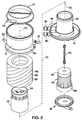
- Figure 2 is an exploded isometric view of a blood oxygenator constructed in accordance with this invention.
- Figure 3 is a side elevation view of the assembled blood oxygenator of Figure 2.
- Figure 4 is a top plan view of the blood oxygenator of Figure 3.
- Figure 5 is a diagrammatic view illustrating the blood, heat transfer fluid and gas mixture flow paths of the blood oxygenator of Figures 2-4.
- Figure 6 is a diagrammatic view illustrating the fabrication of the oxygenator fibre bundle of the blood oxygenator of Figures 2-5.
- Figure 7 is a diagrammatic view of the heat exchanger fibre bundle of the blood oxygenator of Figures 2-5.
- Figure 8 is an enlarged side elevation view of the spindle of the heat exchanger of the blood oxygenator around which is wound the micro-conduit wrapping material.
- Figure 9 is a cross-section view of the spindle of Figure 8 taken along line 9-9 of Figure 8.
- Figure 10 is an end elevation view of the spindle of Figure 8 taken from the right end of Figure 8.
- Figure 11 is a side detail view of polymeric micro-conduit material suitable for construction of the bundle of Figure 7.
- Figure 12 is a magnified side detail view of a portion of the polymeric micro-conduit material of Figure 11.
- Figure 13 is a top plan view of the lower venous gas header of the blood oxygenator. Also visible in this figure are the inner heat exchanger housing, the water inlet nozzle, the water outlet nozzle and the gas mixture outlet nozzle.
- Figure 14 is a sectional view of the lower venous gas header and inner heat exchanger housing taken along line 14-14 of Figure 13.
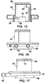
- Figure 15 is a sectional view of the lower venous gas header and inner heat exchanger housing taken along line 15-15 of Figure 13.
- Figure 16 is a front elevation view of the lower venous gas header and inner heat exchanger housing of the blood oxygenator.
- Figure 17 is a side elevation view of the lower venous gas header and inner heat exchanger housing of the blood oxygenator.
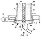
- Figure 18 is an enlarged vertical sectional view of the lower venous gas header and the inner heat exchanger housing with the blood inlet manifold connected. Also illustrated in this view is the micro-conduit fibre bundle of the heat exchanger.
- Figure 19 is a flowchart showing the process steps of a protocol for practising an embodiment of the invention.
-
- Commercially available examples of oxygenators employing microporous hollow fibre membranes for blood/gas exchange include the AFFINITY brand and MAXIMA FORTÉ brand oxygenators available from Medtronic Perfusion Systems, Medtronic, Inc. of Minneapolis, Minnesota, USA (see US Patents Re. 36,125, 5,462,619, and 5,346,621 for the AFFINITY brand oxygenator; and US Patents 5,858,233, 5,823,987, 5,762,875, and 5,718,871 for the MAXIMA FORTÉ brand oxygenator).
- Dow Corning MDX4-4159
Fluid 50% Medical Grade Dispersion is a liquid RTV solution containing 50 percent active silicone ingredients in mixed aliphatic and isopropanol solvents. The active silicone used is an aminofunctional dimethylsiloxane copolymer. The polar nature of the aminofunctional groups and the ability of the fluid to cure cause films to deposit and adhere to metal cutting edges, such as razor blades. The primary known use of MDX4-4159 is dipping, coating and spraying devices to create a thin layer of silicone for lubrication. - The most general expression of the alkoxysilane/alkylsilane copolymer coating for use in the invention is a random or block copolymer of the form:(in which

- R1 represents an alkyl group, preferably a C1-6 alkyl group, e.g. a methyl group;
- R2 represents an alkoxy group, preferably a C1-6 alkoxy group such as -O-CH3 or -O-CH2CH3;
- R3 represents an alkyl or alkoxy group, e.g. as defined for R1 or R2;
- R4 represents a functional group, preferably an aminofunctional group such as - CH2CH2CH2NHCH2CH2NH2;
- R5 represents a functional group, e.g. as defined for R4, or an alkoxy or alkyl group, e.g. as defined for R2 or R1; and
- a, b and c are integers in which a >> b and a >> c).
-
- A preferred embodiment of the invention may be illustrated by considering the design of the MAXIMA FORTÉ oxygenator available from Medtronic Perfusion Systems, Medtronic, Inc., Minneapolis, Minnesota, USA. Of course, details described below that are specific to this device, but not necessary to practice of the invention, may be different in other embodiments of the invention.
- Referring to Figures 1-4, a
blood oxygenator 10 comprises an outer generallycylindrical vessel 12, which is sealed at its upper end by a generally saucer-shaped upper hollowvenous gas header 14. A generally saucer-shaped lower hollowvenous gas header 16 seals the lower end of thevessel 12. Ablood inlet manifold 18 is connected to the centre of the underside of the lowervenous gas header 16. Concentric, generally cylindrical inner and outerheat exchanger housings venous header 16. The upper end of the outerheat exchanger housing 22 includes atransition manifold 24. The interior of the innerheat exchanger housing 20 surrounds and encloses a generally cylindricalfirst fibre bundle 26 made up of a plurality of vertically oriented hollow micro-conduits. These micro-conduits convey blood vertically upward. A second generallycylindrical fibre bundle 28 concentrically surrounds the outerheat exchanger housing 22 and is positioned inside the inner wall of thecylindrical vessel 12. The upper and lower ends of the generally ring-shapedsecond fibre bundle 28 interact with the upper and lowervenous gas headers - The blood inlet manifold 18 (Figure 3) includes a barbed
blood inlet nozzle 30 which bends downwardly at an angle relative to the central vertical axis of thevessel 12. A barbed blood outlet nozzle 32 (Figures 3 and 4) extends horizontally from the exterior of an enlarged or flaredportion 12a of thevessel 12. A standard Leur fitting 34 (Figure 3) extends vertically from the base of theblood outlet nozzle 32. A thermometer probe fitting 36 (Figure 4) extends horizontally from the base of theblood outlet nozzle 32. - Inlet and
outlet nozzles 38 and 40 (Figures 2 and 4) for a heat transfer fluid such as water extend horizontally from one side of the lowvenous gas header 16 and communicate with water flow passages inside the innerheat exchanger housing 20. A barbed de-bubbler nozzle 42 (Figure 3) extends upwardly at an angle from the flaredportion 12a of thevessel 12. A gas mixture inlet nozzle 44 (Figures 2, 3 and 4) extends horizontally from the periphery of the uppervenous gas header 14. A gas mixture outlet nozzle 46 (Figures 2 and 4) extends from the periphery of the lowervenous gas header 16 parallel to the water inlet andoutlet nozzles - The blood, heat transfer fluid and gas mixture flow paths of the
blood oxygenator 10 can best be understood by way of reference to the diagrammatic vertical sectional view of Figure 5. In that figure, the flow of blood is illustrated diagrammatically by the hold solid arrows. The dashed lines illustrate the flow of heat transfer fluid (water). The flow of gas mixture is illustrated by the sequence of dots. Blood from the patient flows through tubing (not illustrated) connected to theblood inlet nozzle 30. This incoming blood spreads out through theblood inlet manifold 18 and travels vertically through the micro-conduits of thefirst fibre bundle 26 of the central heat exchanger that forms the core of theblood oxygenator 10. Water flows in through theinlet nozzle 38 vertically to the top of the heatexchanger fibre bundle 26 through a separate channel isolated from thefibre bundle 26. The water is then directed down and across the outside of the micro-conduits of thefibre bundle 26. The water flows around the outside of the micro-conduits opposite the flow of the blood within the micro-conduits. The water exiting from the lower end of thefirst fibre bundle 26 exits through theoutlet nozzle 40. - The water is heated or cooled outside the blood oxygenator, as necessary to regulate the temperature of the blood flowing through the micro-conduits of the heat exchanger. The use of a counter-flow heat exchanger provides optimum heat exchange efficiency. However, as noted above, the counter-flow design is not essential to the invention.
- The temperature of the blood can be monitored by a circuit (not illustrated) that includes a thermistor or other temperature sensing device (not illustrated) mounted inside the thermometer probe fitting 36 (Figures 3 and 4). The thermometer probe fitting 36 is a preferred location for connection of an electrical bridge to the blood side of the heat exchanger, since the temperature sensing device is likely to be coincidentally an electrically conductive material (typically metal) already in physical contact with the blood. Thus, the invention may be implemented by connecting a conductive bridge between the temperature sensing device and any convenient location on the other side of the heat exchanger.
- Blood exiting from the upper end of the first fibre bundle 26 (Figure 5) of the heat exchanger is directed radially outwardly by the
transition manifold 24. This blood then travels around the outside of the fibres of thesecond fibre bundle 28 that forms the oxygenator. The blood travels downwardly past the outside surfaces of the fibres of thesecond fibre bundle 28. When the blood reaches the lower portion of thesecond fibre bundle 28, it is collected in an outlet manifold defined by the flaredportion 12a of the vessel and exits through theblood outlet nozzle 32. Theblood outlet nozzle 32 is connected to tubing (not illustrated) for returning the blood to the patient. - A gas mixture rich in oxygen from a pressurized source (not illustrated) is conveyed through a hose (not illustrated), through the gas
mixture inlet nozzle 44, and into the uppervenous gas header 14. Theupper gas header 14 communicates with the upper ends of the fibres in thesecond fibre bundle 28 forming the membrane oxygenator. The oxygen-rich gas mixture travels down through the interior of the fibres in thefibre bundle 28. These fibres are micro-porous. Carbon dioxide from the blood surrounding the fibres in thebundle 28 diffuses through the walls of the fibres into the gas mixture. Similarly, oxygen from the gas mixture inside the fibres of thebundle 28 diffuses through the micro-pores into the blood. The gas mixture now having an elevated carbon dioxide content exits the lower ends of the fibres of thesecond fibre bundle 28 into the lowervenous gas header 16 and then exits therefrom via the gasmixture outlet nozzle 46. This gas mixture now has a lower oxygen content. Thenozzle 46 is connected to another gas hose (not illustrated). - Figure 7 is a diagrammatic illustration of the
first fibre bundle 26 which serves as the core of the heat exchanger portion of theblood oxygenator 10. Thefibre bundle 26 has a generally cylindrical configuration and comprises approximately 5,400 vertically (axially) extendinghollow fibres 50. Preferably the fibres are provided as a continuous long web of micro-conduit wrapping material in which the fibres are held together by a thin, flexible, horizontally extending woven interconnect. Such wrapping material is commercially available from Mitsubishi Rayon, Co., Ltd. under the designation HFE430-1 Hollow Fibre. This material uses polyethylene fibres. Similar wrapping material is also commercially available from Hoechst Celanese Corporation under the designation Heat Exchanger Fibre Mat. This material uses polypropylene fibres. - The micro-conduit wrapping material of the heat exchanger core is wound about a central, vertically orientated elongated spindle 52 (Figure 8). The
spindle 52 has anintermediate segment 54 having a cross-shaped cross-section, as best seen in Figure 9. Thespindle 52 has enlarged driving ends 56 connected to the opposite ends of theintermediate segment 54. Each of the driving ends 56 has a pair of parallel extending ribs 58 (Figure 10) which are used to lock the spindle into a winding machine (not illustrated). This machine is utilized to wind the micro-conduit wrapping material about thespindle 52. Preferably the micro-conduit wrapping material is compactly wound about thecentral spindle 52, but without any substantial tension on the web. - As mentioned above, the micro-conduit may be provided in a heat exchanger micro-conduit wrapping material. The wrapping material comprises micro-conduit fibres attached to a thin flexible interconnect, such as woven netting, to maintain the fibres at predetermined spacings in substantially parallel alignment with each other. The wrapping material is wrapped about an elongated spindle having first and second ends, such that the ends of each fibre reside proximate the spindle's first and second ends. After the ends of the fibres are trimmed as needed, a shell is placed around the wrapping material and spindle. Opposing first and second seals are created by applying potting compound between fibres proximate the spindle's first end and proximate the spindle's second end.
- A shown in detail in Figures 11 and 12, the heat exchanger micro-conduit, "micro-conduit" for short, preferably comprises a plurality of
small fibres 100, as shown in Figure 11. In Figure 11, thefibres 100 are arranged in a "mat" ofmicro-conduit wrapping material 102, which is described in greater detail below. Eachfibre 100 comprises an elongated two-ended fibre. Eachfibre 100 is hollow, with a cross-sectional shape preferably being rounded, or alternatively triangular, rectangular, or another appropriate shape. Since thefibres 100 are hollow, eachfibre 100 defines aninner channel 150 having aninner surface 152, as shown in Figure 12. In the illustrated embodiment, the outer diameter of the fibre is about 475 µm while the diameter of theinner channel 150 is about 428 µm. However, a wide variety of inner and outer diameters may be used, depending upon the requirements of the particular application. The difference between the inner and outer diameters is preferably small, to encourage heat exchange through the fibres' walls. Thefibres 100 may be about 10 cm long, for example. However, a wide range of fibre lengths may be used, depending upon the requirements of the particular application. - The
fibres 100 may be made from a plastic material such as polypropylene, polyethylene, a different polymeric substance, or another material that is inexpensive, pharmacologically safe, lightweight, easily cut, and flexible. The material of thefibres 100 must also be easily formed into fibres with sufficiently small inner and outer dimensions. Preferably thefibres 100 would be made of a hydrophilic material, however, micro-conduit made of such material is not presently commercially available. - As mentioned above, Figure 11 illustrates a section of
micro-conduit wrapping material 102. Thematerial 102 includes a thinflexible interconnect 104 that maintains thefibres 100 at predetermined spacings in substantially parallel alignment with each other. In the illustrated embodiment, the interconnect comprises substantially parallel lengths of flexible thread that are woven or khotted to hold the fibres about 0.5 mm apart, generally parallel to each other. The wrappingmaterial 102 aids in positioning thefibres 100 during construction of a blood heat exchanger, as discussed below. - The mat or wrapping
material 102 may be made of commercially available product from Mitsubishi Rayon Co., Ltd. sold under the designation HFE 430-1 Hollow Fibre, which uses polyethylene fibres. Similar wrapping material is also commercially available from Hoechst Celanese Corp. under the designation Heat Exchanger Fibre Mat, which uses polypropylene fibres. - To manufacture the blood heat exchanger, the
micro-conduit wrapping material 102 is wrapped about the spindle, the fibres are installed into the shell, and the upper and lower seals are formed by injecting potting compound between thefibres 100 near the upper and lower surfaces of the core. Sufficient potting compound is applied to substantially seal the spaces between the fibres. Then, thefibres 100 are trimmed near each end of the spindle. Preferably, the trimmedfibres 100 form uniform flat upper and lower surfaces of the core. With the seals in place, liquids such as aqueous priming solution and blood may be directed into thefibres 100 through their ends, without leaking any liquid into the spaces between the fibres. Finally, the manifolds are attached to the shell. Also, hoses and other plumbing lines are attached to the heat exchanger 300 as needed, for transportation of heat exchange medium, blood, priming solution, oxygen, and other media as appropriate. - Generally, the heat exchanger regulates the temperature of a patient's blood during a medical procedure such as open heart surgery. Due to the large number of
fibres 100 and the small size of the fibres, there is a substantial area of surface contact between the heat exchange medium and the contents of thefibres 100. The temperature of blood flowing through the core is efficiently regulated, due to the high degree of contact between the blood and the heat exchange medium. - The configuration of the lower
venous gas header 16, the innerheat exchanger housing 20, the water inlet andoutlet nozzles mixture outlet nozzle 46, are illustrated in Figures 13-17. These parts, along with the raisedannular wall member 68 that receives theblood inlet manifold 18, are all injection molded as a single unitary piece of plastic. The innerheat exchanger housing 20 is formed with an interior vertical wall member 76 (Figure 15) that defines a water flow channel or path 78 (Figures 13 and 15) which extends vertically along one side of theheat exchanger housing 20. The lower end of thewater flow path 78 communicates with the interior of thewater inlet nozzle 38. The upper end of thewater flow path 78 communicates through a port 80 (Figure 15) into the upper interior of thehousing 20. This permits the incoming heat exchange water to be disbursed around the upper ends of the thousands of micro-conduits orfibres 50 of the heatexchanger fibre bundle 26. As previously explained, this water flows down around the outside of thefibres 50, through anotherport 82, and then out throughwater outlet nozzle 40. The opening of thenozzle 40 is shown at 84 in Figure 15. - The upper end of the cylindrical
heat exchanger housing 20 is molded with a fitting ring 86 (Figures 15 and 17) having an upwardly opening circular recess 88 (Figure 18) for receiving, and interfitting with, a downwardly extending circular flange of the outerheat exchanger housing 22. Thefitting ring 86 is connected to the main part of thehousing 20 by small plastic extensions 91 (Figure 17). - Except for the fibre bundles 26 and 28, and the potting compound comprising the
seals - The practice of the invention may be illustrated by the following protocol, which should be read in conjunction with the flowchart of Figure 19. This protocol covers siloxane coating of PVC tubing, oxygenators (using the Medtronic Maxima Forté as a non-limiting example), and other medical devices.
- The required process equipment includes: adequately vented fume hood; roller or centrifugal pump capable of pumping a minimum of 2 litres/minute; Lindberg/Blue M constant temperature water bath or equivalent; stir-plate (Bibby B212 or equivalent); stir bars; 4000 ml to 6000 ml glass flasks; Viton brand tubing; balance (Mettler 4000 or equivalent); pH metre; 2000 ml to 6000 ml glass volumetric flasks; 500 ml to 2000 ml graduated cylinders; polypropylene and glass funnels; polypropylene and glass containers; aluminum foil; lint-free paper towels; and PVC tubing or equivalent.
- The required process materials are: hexanes (ACS Reagent Grade); deionized water ("DI"); Dow Corning MDX4-4159 fluid; 0.1-N Glacial acetic acid; isopropyl alcohol ("IPA"); and 1.0 N hydrochloric acid.
- Safety glasses and protective gloves should be worn at all times. All operations should be performed in a well vented fume hood. All waste chemicals/solvents should be disposed in appropriate waste containers.
- Stock solutions (defined as solutions that have a defined shelf-life which allows preparation before initiating the actual process) should be prepared as follows.
- Preparation of IPA premix: combine 75.0 g (74.6 wt %) of IPA, 25.0 g (24.9 wt %) of DI, and 0.5 g (00.5 wt %) of 1.0 N HCl. The solution should be covered immediately and allowed to stir for a minimum of 5 minutes. The IPA premix should be stored at ambient temperature in a tightly closed container free from moisture.
- Preparation of aminoalkylsiloxane ("ZX") solids solution may be performed according to either of two options. In the first option, a 3 wt % mixture of ZX solids solution in hexane is formed by combining 1880.0 g (94 wt %) of hexane and 120.0 g (6 wt %) of MDX4-4159. In the second option, a 1.5 wt % ZX solids solution in a IPA/hexane mixture is formed by combining 1580.0 g (79 wt %) of IPA, 360.0 g (18 wt %) of hexane, and 60.0 g (3 wt %) of MDX4-4159.
- Mixing of the IPA premix and ZX solids solution may also be performed according to either of two options. In the first option, mixing of the IPA premix and 3 wt % ZX solids in hexane is performed by combining 2000.0 g (99 wt %) of 3 wt % ZX solids solution and 20.0 g (1 wt %) of IPA premix. In the second option, mixing of the IPA premix and 1.5 wt % ZX solids in IPA/hexane is performed by combining 2000.0 g (99.5 wt %) of 1.5 wt % ZX solids solution and 10.0 g (0.5 wt %) of IPA premix. The solution should be covered immediately and allowed to stir for a minimum of 5 minutes. The ZX solution should be stored at ambient temperature in a tightly closed container free from moisture.
- The ZX coating procedure for PVC tubing involves dipping the tubing in the container of ZX solution for 2 minutes and then removing the tubing from the solution. Removal of excess coating from PVC tubing is performed by allowing excess ZX solution to gravity drain for 1 minute. Then, supply 3 PSI (21 kPa, 5-6 SCFM) for 2 minutes, followed by 10 PSI (69 kPa, 7-8 SCFM) for 10 minutes. Curing of the ZX coating on the PVC tubing is performed with humid air (50 ± 5 % relative humidity) at less than 3 PSI (21 kPa) for 30 minutes, followed by 60 minutes of 5-8 PSI (34-55 kPa) of dry air (0 % relative humidity).
- The coating procedure for microporous hollow fibre membrane oxygenators may be illustrated with the following procedure, which uses, as an example only, the Medtronic MAXIMA FORTÉ brand oxygenator. The procedure is easily adapted to other oxygenators using microporous hollow fibre membranes, such as the Medtronic AFFINITY brand oxygenator, according to principles known in the art.
- To prepare the device for coating, plug two exhaust air ports using any appropriate technique, along with the outlet air port. Position the device in its upright position. The oxygenator must be properly grounded to insure that any static buildup is properly discharged. This can be accomplished by connecting a lead from the thermocouple connector to the micropump. Using a micropump and Viton brand tubing, connect the inlet of the pump to a container of ZX solution and the outlet of the pump to the blood inlet connection of the device. Using Viton brand tubing and the appropriate connections, connect both the recirculation port and blood outlet to the container of ZX solution, thus allowing recirculation of the ZX solution. Connect an air line capable of supplying 1 PSI (7 kPa, 8 LPM) to the inlet gas port. Have an air line capable of supplying 3 to 10 PSI (21 to 69 kPa, 5 to 8 SCFM) to the blood inlet port, which will be used for excess ZX removal.
- To coat the device, supply air to the inlet gas port at less than 1 PSI (7 kPa, 6 LPM). Turn the micropump on full power for two minutes. After the micropump is turned off, continue to supply air to the inlet gas port at 6 LPM.
- To remove excess coating from the device, allow the device to gravity drain for 1 minute. For the next two minutes, continue to supply air to the inlet gas port at less than 1 PSI (7 kpa, 6 LPM) and supply 3 PSI (21 kPa, 5-6 SCFM) to the blood outlet and recirculation port. After the two minute period, supply 1 PSI (7 kPa, 8 LPM) to the inlet gas port and 10 PSI (69 kPa, 7-8 SCFM) to the blood outlet and recirculation port for 10 minutes.
- To cure the device, use humid air (50 ± 5 % relative humidity) at less than 3 PSI (21 kPa) for 30 minutes, and then use 5-8 PSI (34-55 kPa) of dry air (0 % relative humidity) for 60 minutes.
- As for other medical devices, appropriate coating process steps and parameters should take into consideration geometry differences. The curing procedure involves using humid air (50 ± 5 % relative humidity) at less than 3 PSI (21 kPa) for 30 minutes and then 5-8 PSI (34-55 kPa) of dry air (0 % relative humidity) for 60 minutes.
- The success of the invention may be demonstrated by considering the following data. Twelve identical Medtronic MAXIMA FORTÉ brand oxygenators were tested for plasma breakthrough under identical conditions. The oxygenators were considered and tested in six pairs. One member of each pair of oxygenators was coated with aminoalkylsiloxane compound according to the protocol described above. The other member was uncoated. The test measured the time in hours for confirmed plasma breakthrough.
- Results appear below.
Test Devices Control Devices Identifier Time (hours) Identifier Time (hours) T1 97324804 72 C1 29 T1 97324483 34 C2 26 T1 97324458 74 C3 25 T1 97324474 54 C4 14 T1 97324467 36 C5 22 T1 97324753 54 C6 23 Mean 54 Mean 23 Standard 16 Standard 5 Deviation Deviation - The tests of units T2 and T5 were terminated after 34 and 36 hours, respectively, because of excessive inlet pressure (>1000 mm Hg, >1.3 x 10⁵ Pa) buildup. This type of pressure increase is common due to the aging of the test fluid (bovine blood) during the study and is not reflective of the performance of the coating. The test of unit C4 was terminated after 14 hours after the microporous fibre developed a leak, which interfered with effluent specific gravity measurements.
- Using standard t-Test calculations for two samples (assuming unequal variances), the following results were obtained.
Variable 1 Variable 2 Mean 54 23.16666667 Variance 289.6 26.16666667 Observations 6 6 Hypothesized Mean Difference 0 df 6 t Stat 4.250235182 P(T<=t)one-tail 0.002689373 t Critical one-tail 1.943180905 P(T<=t) two tail 0.005378746 t Critical two-tail 2.446913641 - Based on a criterion of p<0.01, the conclusion was that coating the microporous hollow fibre membranes with an aminoalkylsiloxane compound to reduce migration of plasma across the micropores produced large and statistically significant improvement in plasma breakthrough time.
Claims (10)
- A medical device comprising a microporous hollow fibre membrane having a plurality of micropores, in which the membrane is provided with a coating comprising an alkoxysilane/alkylsilane copolymer.
- A device as claimed in claim 1 wherein said coating is effective to reduce migration of plasma across said micropores.
- A device as claimed in claim 1 or claim 2 wherein said coating neither covers nor fills said micropores.
- A device as claimed in any one of claims 1 to 3 wherein said coating increases resistance to plasma breakthrough in the device by changing the surface of the microporous fibre membrane near micropore openings.
- A device as claimed in any preceding claim wherein said copolymer comprises a random or block copolymer of formula:(in which
 R1 represents an alkyl group, preferably methyl;R2 represents an alkoxy group, preferably -O-CH3 or -O-CH2CH3;R3 represents an alkyl or alkoxy group;R4 represents a functional group, preferably -CH2CH2CH2NHCH2CH2NH2;R5 represents a functional group, an alkoxy group or an alkyl group; anda, b and c are integers in which a > b and a > c).
 - A device as claimed in any preceding claim wherein said copolymer comprises an aminoalkylsiloxane.
- A device as claimed in any preceding claim wherein said membrane comprises a polymeric material.
- A device as claimed in any preceding claim which comprises PVC tubing or a blood oxygenator.
- A method of coating a device comprising a microporous hollow fibre membrane, said method comprising the steps of:(a) formulating a coating solution comprising an alkoxysilane/alkylsilane copolymer;(b) contacting said device with the coating solution whereby to form a film of silicone on said membrane; and(c) curing the copolymer on the device.
- A method as claimed in claim 9 wherein said coating solution comprises an active aminofunctional dimethylsiloxane copolymer together with at least one aliphatic solvent and at least one isopropanol solvent.
Applications Claiming Priority (2)
| Application Number | Priority Date | Filing Date | Title |
|---|---|---|---|
| US286804 | 1999-04-06 | ||
| US09/286,804 US6395226B1 (en) | 1999-04-06 | 1999-04-06 | Alkoxysilane/alkysilane copolymer coating of medical devices |
Publications (2)
| Publication Number | Publication Date |
|---|---|
| EP1043035A1 true EP1043035A1 (en) | 2000-10-11 |
| EP1043035B1 EP1043035B1 (en) | 2003-06-04 |
Family
ID=23100227
Family Applications (1)
| Application Number | Title | Priority Date | Filing Date |
|---|---|---|---|
| EP00302871A Expired - Lifetime EP1043035B1 (en) | 1999-04-06 | 2000-04-05 | Coating of membranes for medical devices |
Country Status (4)
| Country | Link |
|---|---|
| US (1) | US6395226B1 (en) |
| EP (1) | EP1043035B1 (en) |
| AT (1) | ATE242019T1 (en) |
| DE (1) | DE60003112T2 (en) |
Cited By (1)
| Publication number | Priority date | Publication date | Assignee | Title |
|---|---|---|---|---|
| WO2008041126A2 (en) | 2006-09-04 | 2008-04-10 | Instituto Superior Técnico | Process of synthesis asymmetric polyurethane based membranes with hemocompatibility characteristics and membranes obtained by said process |
Families Citing this family (12)
| Publication number | Priority date | Publication date | Assignee | Title |
|---|---|---|---|---|
| US7135538B2 (en) | 2003-11-12 | 2006-11-14 | General Electric Company | Transparent polycarbonate-polysiloxane copolymer blend, method for the preparation thereof, and article derived therefrom |
| US9125968B2 (en) * | 2005-03-30 | 2015-09-08 | Boston Scientific Scimed, Inc. | Polymeric/ceramic composite materials for use in medical devices |
| US8008395B2 (en) * | 2005-09-27 | 2011-08-30 | Boston Scientific Scimed, Inc. | Organic-inorganic hybrid particle material and polymer compositions containing same |
| US7716850B2 (en) | 2006-05-03 | 2010-05-18 | Georgia-Pacific Consumer Products Lp | Energy-efficient yankee dryer hood system |
| DE102007001665A1 (en) | 2007-01-11 | 2008-07-17 | Raumedic Ag | Gas exchange membrane, in particular for use in an artificial lung, and method for producing such a gas exchange membrane |
| US9238878B2 (en) | 2009-02-17 | 2016-01-19 | Redwood Bioscience, Inc. | Aldehyde-tagged protein-based drug carriers and methods of use |
| JP6162606B2 (en) | 2011-01-14 | 2017-07-12 | レッドウッド バイオサイエンス, インコーポレイテッド | Aldehyde-tagged immunoglobulin polypeptides and methods of use thereof |
| US8906300B2 (en) | 2011-08-11 | 2014-12-09 | The University Of Kentucky Research Foundation | Even perfusion pump-integrated blood oxygenator |
| US8777832B1 (en) | 2013-03-14 | 2014-07-15 | The University Of Kentucky Research Foundation | Axial-centrifugal flow catheter pump for cavopulmonary assistance |
| CN109071634A (en) | 2016-04-26 | 2018-12-21 | R.P.谢勒技术有限责任公司 | Antibody coupling matter and its preparation and application |
| EP3519084B1 (en) * | 2016-10-01 | 2024-07-03 | Oxymem Limited | A self-coiling hollow fibre membrane |
| CN114746166A (en) | 2019-11-25 | 2022-07-12 | 3M创新有限公司 | Hollow fiber membranes having polydiorganosiloxane polyoxamide copolymer skin layers and methods of making and using the same |
Citations (3)
| Publication number | Priority date | Publication date | Assignee | Title |
|---|---|---|---|---|
| US4909989A (en) * | 1985-09-13 | 1990-03-20 | Terumo Kabushiki Kaisha (Terumo Corporation) | Gas-exchange membrane for an artificial lung |
| US4923679A (en) * | 1984-05-24 | 1990-05-08 | Terumo Kabushiki Kaisha | Hollow fiber membrane type oxygenator and method for manufacturing same |
| WO1991015952A1 (en) * | 1990-04-12 | 1991-10-31 | Cardiopulmonics, Inc. | Gas permeable thrombo-resistant coatings and methods of manufacture |
Family Cites Families (7)
| Publication number | Priority date | Publication date | Assignee | Title |
|---|---|---|---|---|
| IT973303B (en) * | 1972-03-28 | 1974-06-10 | Rhone Poulenc Sa | STABLE STABLE BINDERS BASED ON ALKYL SILICATES AND TITANATES AND OR THEIR POLYMERS AND FILMOGENIC RESINS |
| US4049873A (en) * | 1975-01-28 | 1977-09-20 | Imperial Chemical Industries Limited | Surface treating compositions |
| US4906465A (en) * | 1987-10-19 | 1990-03-06 | Massachusetts Institute Of Technology | Antithrombogenic devices containing polysiloxanes |
| US4912240A (en) * | 1988-08-01 | 1990-03-27 | Dow Corning Corporation | Organofunctional betaine modified siloxanes |
| ATE202942T1 (en) | 1994-04-15 | 2001-07-15 | Cobe Cardiovascular Inc | BLOOD COMPATIBLE COATED ITEM |
| US6024918A (en) * | 1998-03-13 | 2000-02-15 | Medtronic, Inc. | Method for attachment of biomolecules to surfaces of medical devices |
| US6136938A (en) * | 1999-03-05 | 2000-10-24 | Dow Corning Corporation | Silicone terpolymers containing dimethyl higher alkyl and repeating units |
-
1999
- 1999-04-06 US US09/286,804 patent/US6395226B1/en not_active Expired - Lifetime
-
2000
- 2000-04-05 EP EP00302871A patent/EP1043035B1/en not_active Expired - Lifetime
- 2000-04-05 AT AT00302871T patent/ATE242019T1/en not_active IP Right Cessation
- 2000-04-05 DE DE60003112T patent/DE60003112T2/en not_active Expired - Fee Related
Patent Citations (3)
| Publication number | Priority date | Publication date | Assignee | Title |
|---|---|---|---|---|
| US4923679A (en) * | 1984-05-24 | 1990-05-08 | Terumo Kabushiki Kaisha | Hollow fiber membrane type oxygenator and method for manufacturing same |
| US4909989A (en) * | 1985-09-13 | 1990-03-20 | Terumo Kabushiki Kaisha (Terumo Corporation) | Gas-exchange membrane for an artificial lung |
| WO1991015952A1 (en) * | 1990-04-12 | 1991-10-31 | Cardiopulmonics, Inc. | Gas permeable thrombo-resistant coatings and methods of manufacture |
Cited By (2)
| Publication number | Priority date | Publication date | Assignee | Title |
|---|---|---|---|---|
| WO2008041126A2 (en) | 2006-09-04 | 2008-04-10 | Instituto Superior Técnico | Process of synthesis asymmetric polyurethane based membranes with hemocompatibility characteristics and membranes obtained by said process |
| US9181384B2 (en) | 2006-09-04 | 2015-11-10 | Instituto Superior Tecnico | Process of synthesis asymmetric polyurethane based membranes with hemocompatibility characteristics and membranes obtained by said process |
Also Published As
| Publication number | Publication date |
|---|---|
| US6395226B1 (en) | 2002-05-28 |
| EP1043035B1 (en) | 2003-06-04 |
| DE60003112D1 (en) | 2003-07-10 |
| DE60003112T2 (en) | 2004-05-06 |
| ATE242019T1 (en) | 2003-06-15 |
Similar Documents
| Publication | Publication Date | Title |
|---|---|---|
| EP1043035B1 (en) | Coating of membranes for medical devices | |
| CA1158510A (en) | Hollow fiber-type artificial lung having enclosed heat exchanger | |
| EP0164025B1 (en) | Hollow fiber membrane type oxygenator and method for manufacturing same | |
| CA1128393A (en) | Oxygenator | |
| US5162102A (en) | Medical instrument and production thereof | |
| EP0908191B1 (en) | Hollow fiber membrane oxygenator | |
| EP0100552B1 (en) | Hydrophilized membrane of porous hydrophobic material and process of producing same | |
| US5876667A (en) | Blood heat exchange system employing micro-conduit | |
| JPS5886172A (en) | Medical substance moving apparatus | |
| JPS6241742B2 (en) | ||
| EP0223626B1 (en) | Membrane type artificial lung and method for manufacture thereof | |
| US5922281A (en) | Surface treatment for micro-conduits employed in blood heat exchange system | |
| JP2888607B2 (en) | Composite membrane for artificial lung, method for producing the same, and composite membrane-type artificial lung using the same | |
| JP4317183B2 (en) | Hollow fiber membrane external blood perfusion oxygenator | |
| JP3048652B2 (en) | Manufacturing method of membrane oxygenator | |
| JPH0548135B2 (en) | ||
| JP3090701B2 (en) | Composite membrane for artificial lung, method for producing the same, and composite membrane-type artificial lung using the same | |
| JP2000042100A (en) | Hollow fiber membrane type liquid treatment apparatus | |
| JPS641149B2 (en) | ||
| JPS60249968A (en) | Hollow fiber membrane type artificial lung | |
| JPS60249967A (en) | Hollow fiber membrane type artificial lung and its production | |
| JPH0119902B2 (en) | ||
| JPS60249969A (en) | Hollow fiber membrane type artificial lung |
Legal Events
| Date | Code | Title | Description |
|---|---|---|---|
| PUAI | Public reference made under article 153(3) epc to a published international application that has entered the european phase |
Free format text: ORIGINAL CODE: 0009012 |
|
| AK | Designated contracting states |
Kind code of ref document: A1 Designated state(s): AT BE CH CY DE DK ES FI FR GB GR IE IT LI LU MC NL PT SE |
|
| AX | Request for extension of the european patent |
Free format text: AL;LT;LV;MK;RO;SI |
|
| 17P | Request for examination filed |
Effective date: 20010409 |
|
| AKX | Designation fees paid |
Free format text: AT BE CH CY DE DK ES FI FR GB GR IE IT LI LU MC NL PT SE |
|
| 17Q | First examination report despatched |
Effective date: 20010622 |
|
| GRAH | Despatch of communication of intention to grant a patent |
Free format text: ORIGINAL CODE: EPIDOS IGRA |
|
| GRAH | Despatch of communication of intention to grant a patent |
Free format text: ORIGINAL CODE: EPIDOS IGRA |
|
| GRAA | (expected) grant |
Free format text: ORIGINAL CODE: 0009210 |
|
| AK | Designated contracting states |
Designated state(s): AT BE CH CY DE DK ES FI FR GB GR IE IT LI LU MC NL PT SE |
|
| PG25 | Lapsed in a contracting state [announced via postgrant information from national office to epo] |
Ref country code: IT Free format text: LAPSE BECAUSE OF FAILURE TO SUBMIT A TRANSLATION OF THE DESCRIPTION OR TO PAY THE FEE WITHIN THE PRESCRIBED TIME-LIMIT;WARNING: LAPSES OF ITALIAN PATENTS WITH EFFECTIVE DATE BEFORE 2007 MAY HAVE OCCURRED AT ANY TIME BEFORE 2007. THE CORRECT EFFECTIVE DATE MAY BE DIFFERENT FROM THE ONE RECORDED. Effective date: 20030604 Ref country code: AT Free format text: LAPSE BECAUSE OF FAILURE TO SUBMIT A TRANSLATION OF THE DESCRIPTION OR TO PAY THE FEE WITHIN THE PRESCRIBED TIME-LIMIT Effective date: 20030604 Ref country code: CH Free format text: LAPSE BECAUSE OF FAILURE TO SUBMIT A TRANSLATION OF THE DESCRIPTION OR TO PAY THE FEE WITHIN THE PRESCRIBED TIME-LIMIT Effective date: 20030604 Ref country code: BE Free format text: LAPSE BECAUSE OF FAILURE TO SUBMIT A TRANSLATION OF THE DESCRIPTION OR TO PAY THE FEE WITHIN THE PRESCRIBED TIME-LIMIT Effective date: 20030604 Ref country code: LI Free format text: LAPSE BECAUSE OF FAILURE TO SUBMIT A TRANSLATION OF THE DESCRIPTION OR TO PAY THE FEE WITHIN THE PRESCRIBED TIME-LIMIT Effective date: 20030604 Ref country code: CY Free format text: LAPSE BECAUSE OF FAILURE TO SUBMIT A TRANSLATION OF THE DESCRIPTION OR TO PAY THE FEE WITHIN THE PRESCRIBED TIME-LIMIT Effective date: 20030604 Ref country code: FI Free format text: LAPSE BECAUSE OF FAILURE TO SUBMIT A TRANSLATION OF THE DESCRIPTION OR TO PAY THE FEE WITHIN THE PRESCRIBED TIME-LIMIT Effective date: 20030604 |
|
| REG | Reference to a national code |
Ref country code: GB Ref legal event code: FG4D |
|
| REG | Reference to a national code |
Ref country code: CH Ref legal event code: EP |
|
| REG | Reference to a national code |
Ref country code: IE Ref legal event code: FG4D |
|
| REF | Corresponds to: |
Ref document number: 60003112 Country of ref document: DE Date of ref document: 20030710 Kind code of ref document: P |
|
| PG25 | Lapsed in a contracting state [announced via postgrant information from national office to epo] |
Ref country code: DK Free format text: LAPSE BECAUSE OF FAILURE TO SUBMIT A TRANSLATION OF THE DESCRIPTION OR TO PAY THE FEE WITHIN THE PRESCRIBED TIME-LIMIT Effective date: 20030904 Ref country code: GR Free format text: LAPSE BECAUSE OF FAILURE TO SUBMIT A TRANSLATION OF THE DESCRIPTION OR TO PAY THE FEE WITHIN THE PRESCRIBED TIME-LIMIT Effective date: 20030904 Ref country code: SE Free format text: LAPSE BECAUSE OF FAILURE TO SUBMIT A TRANSLATION OF THE DESCRIPTION OR TO PAY THE FEE WITHIN THE PRESCRIBED TIME-LIMIT Effective date: 20030904 Ref country code: PT Free format text: LAPSE BECAUSE OF FAILURE TO SUBMIT A TRANSLATION OF THE DESCRIPTION OR TO PAY THE FEE WITHIN THE PRESCRIBED TIME-LIMIT Effective date: 20030904 |
|
| PG25 | Lapsed in a contracting state [announced via postgrant information from national office to epo] |
Ref country code: ES Free format text: LAPSE BECAUSE OF FAILURE TO SUBMIT A TRANSLATION OF THE DESCRIPTION OR TO PAY THE FEE WITHIN THE PRESCRIBED TIME-LIMIT Effective date: 20030915 |
|
| REG | Reference to a national code |
Ref country code: CH Ref legal event code: PL |
|
| ET | Fr: translation filed | ||
| PG25 | Lapsed in a contracting state [announced via postgrant information from national office to epo] |
Ref country code: IE Free format text: LAPSE BECAUSE OF NON-PAYMENT OF DUE FEES Effective date: 20040405 Ref country code: GB Free format text: LAPSE BECAUSE OF NON-PAYMENT OF DUE FEES Effective date: 20040405 Ref country code: LU Free format text: LAPSE BECAUSE OF NON-PAYMENT OF DUE FEES Effective date: 20040405 |
|
| PLBE | No opposition filed within time limit |
Free format text: ORIGINAL CODE: 0009261 |
|
| STAA | Information on the status of an ep patent application or granted ep patent |
Free format text: STATUS: NO OPPOSITION FILED WITHIN TIME LIMIT |
|
| PG25 | Lapsed in a contracting state [announced via postgrant information from national office to epo] |
Ref country code: MC Free format text: LAPSE BECAUSE OF NON-PAYMENT OF DUE FEES Effective date: 20040430 |
|
| 26N | No opposition filed |
Effective date: 20040305 |
|
| GBPC | Gb: european patent ceased through non-payment of renewal fee | ||
| REG | Reference to a national code |
Ref country code: IE Ref legal event code: MM4A |
|
| PGFP | Annual fee paid to national office [announced via postgrant information from national office to epo] |
Ref country code: NL Payment date: 20050316 Year of fee payment: 6 |
|
| PG25 | Lapsed in a contracting state [announced via postgrant information from national office to epo] |
Ref country code: NL Free format text: LAPSE BECAUSE OF NON-PAYMENT OF DUE FEES Effective date: 20061101 |
|
| NLV4 | Nl: lapsed or anulled due to non-payment of the annual fee |
Effective date: 20061101 |
|
| PGFP | Annual fee paid to national office [announced via postgrant information from national office to epo] |
Ref country code: DE Payment date: 20070430 Year of fee payment: 8 |
|
| PGFP | Annual fee paid to national office [announced via postgrant information from national office to epo] |
Ref country code: FR Payment date: 20070404 Year of fee payment: 8 |
|
| PG25 | Lapsed in a contracting state [announced via postgrant information from national office to epo] |
Ref country code: DE Free format text: LAPSE BECAUSE OF NON-PAYMENT OF DUE FEES Effective date: 20081101 |
|
| REG | Reference to a national code |
Ref country code: FR Ref legal event code: ST Effective date: 20081231 |
|
| PG25 | Lapsed in a contracting state [announced via postgrant information from national office to epo] |
Ref country code: FR Free format text: LAPSE BECAUSE OF NON-PAYMENT OF DUE FEES Effective date: 20080430 |