EP1042952B1 - Konstruktion zum automatischen Melken von Tieren - Google Patents
Konstruktion zum automatischen Melken von Tieren Download PDFInfo
- Publication number
- EP1042952B1 EP1042952B1 EP00116842A EP00116842A EP1042952B1 EP 1042952 B1 EP1042952 B1 EP 1042952B1 EP 00116842 A EP00116842 A EP 00116842A EP 00116842 A EP00116842 A EP 00116842A EP 1042952 B1 EP1042952 B1 EP 1042952B1
- Authority
- EP
- European Patent Office
- Prior art keywords
- box
- construction
- animal
- boxes
- milking
- Prior art date
- Legal status (The legal status is an assumption and is not a legal conclusion. Google has not performed a legal analysis and makes no representation as to the accuracy of the status listed.)
- Expired - Lifetime
Links
- 241001465754 Metazoa Species 0.000 title claims abstract description 83
- 238000010276 construction Methods 0.000 title claims abstract description 29
- 239000012141 concentrate Substances 0.000 claims abstract description 8
- 241000283690 Bos taurus Species 0.000 claims abstract 2
- 238000005192 partition Methods 0.000 claims description 8
- 210000000481 breast Anatomy 0.000 claims description 6
- 238000004140 cleaning Methods 0.000 claims description 2
- 238000001514 detection method Methods 0.000 description 16
- 210000002445 nipple Anatomy 0.000 description 9
- 230000004936 stimulating effect Effects 0.000 description 3
- 230000006651 lactation Effects 0.000 description 2
- 244000144972 livestock Species 0.000 description 2
- 239000008267 milk Substances 0.000 description 2
- 210000004080 milk Anatomy 0.000 description 2
- 235000013336 milk Nutrition 0.000 description 2
- 230000000694 effects Effects 0.000 description 1
- 244000144980 herd Species 0.000 description 1
- 238000004519 manufacturing process Methods 0.000 description 1
- 238000012986 modification Methods 0.000 description 1
- 230000004048 modification Effects 0.000 description 1
Images


Classifications
-
- A—HUMAN NECESSITIES
- A01—AGRICULTURE; FORESTRY; ANIMAL HUSBANDRY; HUNTING; TRAPPING; FISHING
- A01J—MANUFACTURE OF DAIRY PRODUCTS
- A01J5/00—Milking machines or devices
- A01J5/017—Automatic attaching or detaching of clusters
- A01J5/0175—Attaching of clusters
-
- A—HUMAN NECESSITIES
- A01—AGRICULTURE; FORESTRY; ANIMAL HUSBANDRY; HUNTING; TRAPPING; FISHING
- A01K—ANIMAL HUSBANDRY; AVICULTURE; APICULTURE; PISCICULTURE; FISHING; REARING OR BREEDING ANIMALS, NOT OTHERWISE PROVIDED FOR; NEW BREEDS OF ANIMALS
- A01K1/00—Housing animals; Equipment therefor
- A01K1/12—Milking stations
-
- A—HUMAN NECESSITIES
- A01—AGRICULTURE; FORESTRY; ANIMAL HUSBANDRY; HUNTING; TRAPPING; FISHING
- A01K—ANIMAL HUSBANDRY; AVICULTURE; APICULTURE; PISCICULTURE; FISHING; REARING OR BREEDING ANIMALS, NOT OTHERWISE PROVIDED FOR; NEW BREEDS OF ANIMALS
- A01K11/00—Marking of animals
- A01K11/006—Automatic identification systems for animals, e.g. electronic devices, transponders for animals
Definitions
- the present invention relates to a construction for automatically milking animals as described in the preamble of claim 1.
- the animals can freely report at the milking box, lured thereto, for example, because they can get concentrate there, it must be checked whether a sufficiently long period of time has elapsed after the previous milking turn.
- a selection must be effected of the animals reporting at the milking box, more specifically in that sense that only those animals whose previous milking turn was a sufficiently long period of time before, are passed to the milking box.
- an animal identification system constituted by an animal identification sensor present in this selection box and connected to the computer system and by a transponder to be worn by the animal, it can be decided on the basis of a file stored for this animal in the computer system whether the animal is to be sent back to the shed of the construction or must be allowed to go to the milking box.
- Each of the boxes is provided at one side with at least two doors, through which an animal can consecutively and sideways move from one box to the other.
- the doors will be pivotally arranged approximately halfway the long side of a relevant box, and a door will have an end which in the closed state curves towards the midway point of the box.
- the animal By keeping the entrance door of the front box closed and by moving the exit door of the rear box to a second opened state, the animal can be passed back to the shed of the construction, which will be the case when it has been decided in the rear box that the animal cannot yet be milked and consequently is not allowed to go to the milking box.
- Figure 1 shows two boxes 1 and 2 which are contiguous to each other in the lengthwise direction. These boxes are bounded by a frame 3 consisting of a frame portion 4 forming a longitudinal side of the two boxes, the frame portions 5, 6 and 7 forming the short sides of the boxes and doors provided at the other longitudinal side of the boxes 1 and 2, the entrance doors of the boxes 1 and 2 being denoted by the reference numerals 8 and 9 and the exit doors of the boxes by 10 and 11.
- the doors 8 and 10 are pivotal approximately halfway the longitudinal side of box 1, whereas the doors 9 and 11 are pivotal approximately halfway the longitudinal side of box 2. Near their ends the doors 8 to 11 have a portion 12 and 13, 14, 15, respectively, which in the closed condition of the doors extend to the midway point of the relevant boxes.
- inwardly directed portions 12 to 15 are disposed such that, when the doors have been moved to a first opened state, illustrated by means of broken lines in Figure 1, the inwardly extending portions 12 to 15 are predominantly located such that they are in alignment, parallel to the longitudinal direction of the two boxes. Particularly by moving the exit door 10 of box 1 and the entrance door 9 of box 2 to this first opened state, a lateral connecting passage is formed between box 1 and box 2 and an animal can be guided from box 1 into the box 2.
- a partition 16 which extends transversely to the longitudinal direction of the boxes, more specifically in the region of the lateral frame portion 6 between the two boxes.
- This partition 16 is movable in a direction transversely of the longitudinal direction of the boxes, whilst the partition 16 remains in alignment with the transverse frame portion 6.
- an animal can pass from box 1 to box 2 when the doors 9 and 10 have been moved to the first opened state, whilst, when the partition 16 has been moved towards the transverse frame portion 6 and thereafter the door 10 has been moved to a second opened state, illustrated by broken lines in Figure 1, then an animal can be returned from box 1 to the shed of the construction.
- the system can operate in an excellent manner also without the partition 16, as, by keeping the door 9 closed and moving the door 10 to the second opened state, an animal can be denied access to box 2 and will be forced to enter the shed of the construction.
- the movable partition is of importance.
- the boxes 1 and 2 both include an automatic feeding implement 17 and 18. Near these automatic feeders both boxes accommodate an animal identification sensor (not shown in the Figures) which is connected to a computer system, which animal identification sensors form an animal identification system in combination with a transponder worn by the animals. With the aid of this animal identification system it is permanently updated in the computer system which animal is present at which moment in which box. For that purpose the memory of the computer system has a separate file for each animal, in which file all relevant information about the relevant animal has also been stored.
- this file it is recorded when an animal has been milked for the last time, so that it is always known how much time has elapsed between the latest milking turn and the instant an animal has entered the box 1, when an animal has calved last, when the lactation period of an animal has started, how much milk it yields in each milking turn, etc. This information is important to decide whether an animal may enter the box 1, may be milked or not.
- the box 1 is therefore also provided with means for selecting the animals, whilst furthermore the opportunity can be used to clean and optionally massage the udder of the animal to stimulate the milk production, when by means of the animal identification system and the data in the file of the relevant animal in the memory of the computer system it has been decided that the animal may be milked, whilst in addition concentrate can be supplied to the animal in the box 1.
- the box 2 is equipped as a milking box, into which an animal is admitted from box 1 for the purpose of being milked, whilst additional concentrate can be fed to the animal if desired.
- An animal which has recently calved can automatically and/or to the livestock farmer's option be milked one or more times per 24 hour's period more frequently than the average number of times the other animals of the herd, to which the recently calved animal belongs, are milked. Likewise, depending on the beginning of the lactation period of an animal, the animal can be milked more or less times per 24 hour's period. In this and other cases it can automatically and/or to the livestock farmer's option be recorded in the computer system how many times a given animal can be milked in each 24 hour's period and the animals can be stimulated to go at the proper moments, summoned by the computer system, to the boxes 1 and 2.
- stimulating means may be placed all over the construction, more specifically in the lying boxes and in the feeding stations, for stimulating the animal to go to the milking box.
- These stimulating means can, for example, produce sound or light signals or, more in particular, the animals in the lying boxes and in the feeding stations can be given electric shocks, which contribute to forcing the animals to go from the lying box or feeding station to the milking boxes 1 and 2 through the shed.
- a suitable shed lay-out more specifically such a shed lay-out in which the animals must follow a fixed path through the shed to the milking box, will definitely contribute thereto.
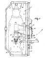
- Figures 2 and 3 are a plan view and a side view, respectively, of only the milking box 2.
- a milking robot 19 is present, which includes a robot arm construction 20, at the end of which a robot head 21 is disposed which serves as a carrier for four teat cups 22.
- the milking robot 19 includes a carrier structure 23 for a detection member 24.
- the robot arm construction 20 carrying the robot head 21 and the teat cups 22 is independently movable with respect to the carrier structure 23 with the detection member 24.
- the robot arm structure 20 is constituted by a carrier element 25 which is movable over a rail 37, parallel to the frame portion 4, and to which a carrier 27 which can be moved up and down is attached by means of a parallelogram structure 26.
- the carrier 27 At its bottom side the carrier 27 is provided with a supporting element 28 which is rigidly connected thereto and extends inwardly and slightly forwardly.
- a robot arm 30 is connected capable of pivoting about an upwardly directed shaft 29 to the supporting element 28.
- the robot head 21 is attached capable of pivoting about an upwardly directed shaft 31 to the end of the arm 30.
- the carrier structure 23 for the detection member 24 Independently of the robot arm structure 20, which is in a position more advanced to the leading side of the milking box 2, there is disposed, near the rear side of the milking box 2, the carrier structure 23 for the detection member 24. Also the carrier structure 23 includes a carrier element 32 which is movable along the rail 37. This carrier element 32 is constituted by a hollow beam 33, within which an inner beam 34 is disposed capable of moving upwardly and downwardly. At the bottom side of this inner beam 34 a carrier 35 is present which is movable transversely to the longitudinal direction of the milking box 2 and at the end of which carrier 35 a supporting element 36 for the detection member 24 is attached.
- the detection member 24 is designed as a laser which is pivotal about an upwardly directed shaft and produces a very narrow scanning beam, which is moved from a short distance over the teats of the animal, an extremely accurate positional determination of the teats is made possible.
- the detection member 24 can be adjusted to the position shown by moving the detection member to a central position between the two longitudinal sides and by moving it thereafter to a position which is determined from the computer system on the basis of the data stored in the file of the animal about the position of the teats.
- the motion of the detection member 24 is performed totally independently of the robot arm carrier structure 20 of the teat cups 22 and is therefore not obstructed thereby in any way.
- Figure 4 shows an alternative embodiment of the carrier structure 23 for the detection member 24.
- the detection member 24 is then directly disposed at the end of the carrier 35.
- the carrier structure 23 and, more in particular the carrier 35 is in a more advanced position, it will be necessary for the robot arm structure 20 to be adjusted to a more advanced position so as to be able to pivot to under the animal without any obstruction by the carrier structure 23.
- the robot head 21 can be moved rearwardly towards the udder.
- milking box the place in which the animals are present during milking is designated as a milking box. It will be obvious that this milking box may be of any conceivable design; it may also form part of the shed.
- the invention is therefore not limited to the construction shown here and is also not limited to the embodiments described sofar, but also relates to all kinds of modifications thereof, of course in sofar they are within the scope of the accompanying claims.
Landscapes
- Life Sciences & Earth Sciences (AREA)
- Environmental Sciences (AREA)
- Animal Husbandry (AREA)
- Zoology (AREA)
- Biodiversity & Conservation Biology (AREA)
- Birds (AREA)
- Housing For Livestock And Birds (AREA)
- Farming Of Fish And Shellfish (AREA)
- Feeding And Watering For Cattle Raising And Animal Husbandry (AREA)
- Catching Or Destruction (AREA)
Claims (11)
- Vorrichtung zum automatischen Melken von Tieren, wie z. B. Kühen, mit einer Melkbox (2) und einem Melkroboter (19), wobei die Vorrichtung zwei Boxen (1, 2) enthält, die mit ihren Enden aneinander angrenzen, wobei die erste (1) dieser Boxen zum Auswählen und/oder Versorgen von Tieren mit Kraftfutter dient und die zweite (2) als Melkbox ausgebildet ist,
dadurch gekennzeichnet, daß jede der Boxen (1, 2) an einer Seite mindestens zwei Türen (8 bis 11) aufweist, durch die ein Tier auf der Seite nacheinander von einer Box in die andere gehen kann. - Vorrichtung nach Anspruch 1,
dadurch gekennzeichnet, daß die Türen (8 bis 11) etwa in der Mitte der Längsseite einer jeweiligen Box schwenkbar angeordnet sind. - Vorrichtung nach Anspruch 2,
dadurch gekennzeichnet, daß eine Tür (8 bis 11) in geschlossenem Zustand ein Ende (12 bis 15) aufweist, das zur Mitte der Box (1, 2) hin abgerundet ist. - Vorrichtung nach Anspruch 2 oder 3,
dadurch gekennzeichnet, daß die Ausgangstür (10) der hinteren Box (1) und die Eingangstür (9) der vorderen Box (2) in einer ersten Öffnungsstellung es einem in der hinteren Box (1) befindlichen Tier gestatten, in die vordere Box (2) zu gehen. - Vorrichtung nach einem der Ansprüche 2 bis 4,
dadurch gekennzeichnet, daß die Ausgangstür (10) der hinteren Box (1) in einer zweiten Öffnungsstellung, in der die Eingangstür (9) der vorderen Box (2) geschlossen bleibt, ein in der hinteren Box (1) befindliches Tier dazu zwingt, in den Stallbereich der Vorrichtung zurückzukehren. - Vorrichtung nach einem der Ansprüche 2 bis 5,
dadurch gekennzeichnet, daß quer zur Längsrichtung der beiden Boxen (1, 2) in dem Bereich, in dem die Boxen aneinander angrenzen, eine Trennwand (16) vorhanden ist, die in Querrichtung bewegbar ist und von den Boxen (1, 2) wegbewegt wird, wenn ein Tier von der hinteren (1) zur vorderen Box (2) gehen soll, und zu den Boxen (1, 2) hinbewegt wird, wenn ein Tier daran gehindert wird, von der hinteren Box (1) zur vorderen Box (2) zu gehen, und in den Stallbereich der Vorrichtung zurückkehren soll. - Vorrichtung nach einem der vorhergehenden Ansprüche,
dadurch gekennzeichnet, daß jede Box (1, 2) einen automatisch gesteuerten Futtertrog (17, 18) enthält. - Vorrichtung nach einem der vorhergehenden Ansprüche,
dadurch gekennzeichnet, daß jede Box (1, 2) einen Tieridentifikationssensor enthält, der mit einem Computersystem verbunden ist und in Kombination mit einem von jedem der Tiere zu tragenden Transponder ein Tieridentifikationssystem bildet. - Vorrichtung nach Anspruch 8,
dadurch gekennzeichnet, daß mit Hilfe des Tieridentifikationssystems und der in dem Computersystem gespeicherten Information über das in der hinteren Box (1) befindliche Tier entschieden wird, ob dem Tier der Zutritt zur vorderen Box (2) gestattet wird, oder ob es in den Stallbereich der Vorrichtung zurückgeschickt wird. - Vorrichtung nach einem der vorhergehenden Ansprüche,
dadurch gekennzeichnet, daß die hintere Box (1) nicht nur als Auswahlbox dient, sondern auch zum Massieren des Euters eines Tieres, zum Reinigen des Tieres und zu seiner Versorgung mit Kraftfutter. - Vorrichtung nach einem der vorhergehenden Ansprüche,
dadurch gekennzeichnet, daß die Vorrichtung als Laufstall ausgeführt ist.
Applications Claiming Priority (3)
| Application Number | Priority Date | Filing Date | Title |
|---|---|---|---|
| NL9301377 | 1993-08-09 | ||
| NL9301377A NL9301377A (nl) | 1993-08-09 | 1993-08-09 | Inrichting voor het automatisch melken van dieren. |
| EP94202258A EP0638231B2 (de) | 1993-08-09 | 1994-08-05 | Vorrichtung zum automatischen Melken von Tieren |
Related Parent Applications (1)
| Application Number | Title | Priority Date | Filing Date |
|---|---|---|---|
| EP94202258A Division EP0638231B2 (de) | 1993-08-09 | 1994-08-05 | Vorrichtung zum automatischen Melken von Tieren |
Publications (3)
| Publication Number | Publication Date |
|---|---|
| EP1042952A2 EP1042952A2 (de) | 2000-10-11 |
| EP1042952A3 EP1042952A3 (de) | 2001-08-08 |
| EP1042952B1 true EP1042952B1 (de) | 2003-10-29 |
Family
ID=19862740
Family Applications (2)
| Application Number | Title | Priority Date | Filing Date |
|---|---|---|---|
| EP00116842A Expired - Lifetime EP1042952B1 (de) | 1993-08-09 | 1994-08-05 | Konstruktion zum automatischen Melken von Tieren |
| EP94202258A Expired - Lifetime EP0638231B2 (de) | 1993-08-09 | 1994-08-05 | Vorrichtung zum automatischen Melken von Tieren |
Family Applications After (1)
| Application Number | Title | Priority Date | Filing Date |
|---|---|---|---|
| EP94202258A Expired - Lifetime EP0638231B2 (de) | 1993-08-09 | 1994-08-05 | Vorrichtung zum automatischen Melken von Tieren |
Country Status (5)
| Country | Link |
|---|---|
| EP (2) | EP1042952B1 (de) |
| AT (2) | ATE252821T1 (de) |
| DE (2) | DE69433287T2 (de) |
| DK (1) | DK0638231T4 (de) |
| NL (1) | NL9301377A (de) |
Families Citing this family (8)
| Publication number | Priority date | Publication date | Assignee | Title |
|---|---|---|---|---|
| NL9500362A (nl) * | 1994-04-14 | 1995-11-01 | Maasland Nv | Werkwijze voor het automatisch melken van dieren en inrichting waarin deze werkwijze kan worden toegepast. |
| NL1000380C2 (nl) * | 1995-05-17 | 1996-11-19 | Maasland Nv | Dieractiviteitsmeter. |
| DE29723523U1 (de) * | 1997-07-03 | 1998-11-12 | Boekhoff, Volker, 26789 Leer | Vorrichtung zum Schutz von in der Landwirtschaft eingesetzten Geräten, insbesondere Datenverarbeitungsgeräten |
| SE9704174D0 (sv) | 1997-11-14 | 1997-11-14 | Alfa Laval Agri Ab | an automatic milking apparatus |
| JP4121703B2 (ja) | 1997-11-14 | 2008-07-23 | デラヴァル ホルディング アーベー | 動物関連作業を行うための装置 |
| EP1381269B2 (de) | 2001-03-07 | 2014-05-07 | Lattec I/S | Anordnung zur optimierung der produktionsleistung von einer milchtiereherde |
| NL1018146C2 (nl) * | 2001-05-23 | 2002-12-03 | Lely Entpr Ag | Inrichting voor het afkoelen van een melkdier, zoals een koe. |
| NL1032150C1 (nl) * | 2006-07-12 | 2008-01-15 | Maasland Nv | Inrichting voor het automatisch melken van een dier. |
Citations (1)
| Publication number | Priority date | Publication date | Assignee | Title |
|---|---|---|---|---|
| EP0432148A2 (de) * | 1986-11-19 | 1991-06-12 | Prolion B.V. | Ortsbeweglicher Raum oder Container, der ein Gerät zum automatischen Melken von Tieren enthält |
Family Cites Families (8)
| Publication number | Priority date | Publication date | Assignee | Title |
|---|---|---|---|---|
| GB1175588A (en) * | 1967-08-01 | 1969-12-23 | Gascoignes Res & Dev Ltd | Improvements in Milking Installations |
| EP0332229B2 (de) * | 1985-01-16 | 2001-08-22 | Maasland N.V. | Gerät zum Melken von Tieren, z.B. Kühen |
| EP0319523B2 (de) * | 1985-01-16 | 1995-10-25 | C. van der Lely N.V. | Gerät zum automatischen Melken von Tieren |
| EP0630562B1 (de) * | 1985-01-16 | 2000-10-25 | Maasland N.V. | Vorrichtung zum automatischen Melken von Tieren |
| NL191479C (nl) * | 1986-10-06 | 1995-08-04 | Lely Nv C Van Der | Werkwijze en inrichting voor het uit de spenen van dieren afnemen van melkmonsters voorafgaande aan het melken van deze dieren. |
| DE3702465A1 (de) * | 1987-01-28 | 1988-08-11 | Duevelsdorf & Sohn Gmbh & Co K | Verfahren und vorrichtung zum melken und ggfs. fuettern von freilaufenden, identifizierungsmittel tragenden kuehen |
| NL8902505A (de) * | 1989-10-09 | 1991-05-01 | Henderikus Gerhardus Beukeveld | |
| NL9200091A (nl) * | 1992-01-17 | 1993-08-16 | Lely Nv C Van Der | Melkmachine. |
-
1993
- 1993-08-09 NL NL9301377A patent/NL9301377A/nl not_active Application Discontinuation
-
1994
- 1994-08-05 AT AT00116842T patent/ATE252821T1/de not_active IP Right Cessation
- 1994-08-05 DK DK94202258T patent/DK0638231T4/da active
- 1994-08-05 DE DE69433287T patent/DE69433287T2/de not_active Expired - Lifetime
- 1994-08-05 DE DE69426846T patent/DE69426846T3/de not_active Expired - Lifetime
- 1994-08-05 AT AT94202258T patent/ATE199624T1/de not_active IP Right Cessation
- 1994-08-05 EP EP00116842A patent/EP1042952B1/de not_active Expired - Lifetime
- 1994-08-05 EP EP94202258A patent/EP0638231B2/de not_active Expired - Lifetime
Patent Citations (1)
| Publication number | Priority date | Publication date | Assignee | Title |
|---|---|---|---|---|
| EP0432148A2 (de) * | 1986-11-19 | 1991-06-12 | Prolion B.V. | Ortsbeweglicher Raum oder Container, der ein Gerät zum automatischen Melken von Tieren enthält |
Also Published As
| Publication number | Publication date |
|---|---|
| NL9301377A (nl) | 1995-03-01 |
| EP0638231A2 (de) | 1995-02-15 |
| EP1042952A3 (de) | 2001-08-08 |
| DE69426846D1 (de) | 2001-04-19 |
| DE69433287T2 (de) | 2004-08-05 |
| EP1042952A2 (de) | 2000-10-11 |
| DK0638231T3 (da) | 2001-06-18 |
| ATE199624T1 (de) | 2001-03-15 |
| ATE252821T1 (de) | 2003-11-15 |
| DE69426846T3 (de) | 2006-11-02 |
| EP0638231A3 (de) | 1995-04-05 |
| EP0638231B2 (de) | 2006-04-05 |
| DE69426846T2 (de) | 2001-09-13 |
| DK0638231T4 (da) | 2006-07-24 |
| EP0638231B1 (de) | 2001-03-14 |
| DE69433287D1 (de) | 2003-12-04 |
Similar Documents
| Publication | Publication Date | Title |
|---|---|---|
| EP0634097B1 (de) | Gerät zum automatischen Melken von Tieren | |
| EP0194729B1 (de) | Gerät zum Melken von Tieren | |
| US5596945A (en) | Construction for automatically milking animals | |
| EP0551960B1 (de) | Vorrichtung zum automatischen Melken von Tieren | |
| EP1120034B1 (de) | Konstruktion mit einem Gerät zum automatischen Melken von Tieren | |
| EP0951824B1 (de) | Vorrichtung zum automatischen Melken von Tieren | |
| EP1042952B1 (de) | Konstruktion zum automatischen Melken von Tieren | |
| EP0693871B1 (de) | Gerät zum automatischen melken von tieren | |
| EP0716567B1 (de) | Vorrichtung mit einem gerät zum automatischen melken von tieren | |
| EP0990385B1 (de) | Konstruktion zum Melken von Tieren | |
| EP0638232B2 (de) | Vorrichtung zum automatischen Melken von Tieren | |
| CA2388923A1 (en) | Means for improved milking | |
| EP0634095B1 (de) | Vorrichtung zum automatischen Melken von Tieren | |
| CA2243420A1 (en) | A construction including an implement for automatically milking animals |
Legal Events
| Date | Code | Title | Description |
|---|---|---|---|
| PUAI | Public reference made under article 153(3) epc to a published international application that has entered the european phase |
Free format text: ORIGINAL CODE: 0009012 |
|
| AC | Divisional application: reference to earlier application |
Ref document number: 638231 Country of ref document: EP |
|
| AK | Designated contracting states |
Kind code of ref document: A2 Designated state(s): AT BE CH DE DK FR GB LI NL SE |
|
| RIC1 | Information provided on ipc code assigned before grant |
Free format text: 7A 01J 7/00 A, 7A 01K 1/12 B, 7A 01K 11/00 B, 7A 01J 5/017 B |
|
| PUAL | Search report despatched |
Free format text: ORIGINAL CODE: 0009013 |
|
| AK | Designated contracting states |
Kind code of ref document: A3 Designated state(s): AT BE CH DE DK FR GB LI NL SE |
|
| 17P | Request for examination filed |
Effective date: 20011126 |
|
| AKX | Designation fees paid |
Free format text: AT BE CH DE DK FR GB LI NL SE |
|
| GRAH | Despatch of communication of intention to grant a patent |
Free format text: ORIGINAL CODE: EPIDOS IGRA |
|
| GRAH | Despatch of communication of intention to grant a patent |
Free format text: ORIGINAL CODE: EPIDOS IGRA |
|
| GRAA | (expected) grant |
Free format text: ORIGINAL CODE: 0009210 |
|
| AC | Divisional application: reference to earlier application |
Ref document number: 0638231 Country of ref document: EP Kind code of ref document: P |
|
| AK | Designated contracting states |
Kind code of ref document: B1 Designated state(s): AT BE CH DE DK FR GB LI NL SE |
|
| PG25 | Lapsed in a contracting state [announced via postgrant information from national office to epo] |
Ref country code: LI Free format text: LAPSE BECAUSE OF FAILURE TO SUBMIT A TRANSLATION OF THE DESCRIPTION OR TO PAY THE FEE WITHIN THE PRESCRIBED TIME-LIMIT Effective date: 20031029 Ref country code: CH Free format text: LAPSE BECAUSE OF FAILURE TO SUBMIT A TRANSLATION OF THE DESCRIPTION OR TO PAY THE FEE WITHIN THE PRESCRIBED TIME-LIMIT Effective date: 20031029 Ref country code: AT Free format text: LAPSE BECAUSE OF FAILURE TO SUBMIT A TRANSLATION OF THE DESCRIPTION OR TO PAY THE FEE WITHIN THE PRESCRIBED TIME-LIMIT Effective date: 20031029 Ref country code: NL Free format text: LAPSE BECAUSE OF FAILURE TO SUBMIT A TRANSLATION OF THE DESCRIPTION OR TO PAY THE FEE WITHIN THE PRESCRIBED TIME-LIMIT Effective date: 20031029 Ref country code: BE Free format text: LAPSE BECAUSE OF FAILURE TO SUBMIT A TRANSLATION OF THE DESCRIPTION OR TO PAY THE FEE WITHIN THE PRESCRIBED TIME-LIMIT Effective date: 20031029 |
|
| REG | Reference to a national code |
Ref country code: GB Ref legal event code: FG4D |
|
| REG | Reference to a national code |
Ref country code: CH Ref legal event code: EP |
|
| REF | Corresponds to: |
Ref document number: 69433287 Country of ref document: DE Date of ref document: 20031204 Kind code of ref document: P |
|
| PG25 | Lapsed in a contracting state [announced via postgrant information from national office to epo] |
Ref country code: SE Free format text: LAPSE BECAUSE OF FAILURE TO SUBMIT A TRANSLATION OF THE DESCRIPTION OR TO PAY THE FEE WITHIN THE PRESCRIBED TIME-LIMIT Effective date: 20040129 Ref country code: DK Free format text: LAPSE BECAUSE OF FAILURE TO SUBMIT A TRANSLATION OF THE DESCRIPTION OR TO PAY THE FEE WITHIN THE PRESCRIBED TIME-LIMIT Effective date: 20040129 |
|
| NLV1 | Nl: lapsed or annulled due to failure to fulfill the requirements of art. 29p and 29m of the patents act | ||
| REG | Reference to a national code |
Ref country code: CH Ref legal event code: PL |
|
| ET | Fr: translation filed | ||
| PG25 | Lapsed in a contracting state [announced via postgrant information from national office to epo] |
Ref country code: GB Free format text: LAPSE BECAUSE OF NON-PAYMENT OF DUE FEES Effective date: 20040805 |
|
| PLBE | No opposition filed within time limit |
Free format text: ORIGINAL CODE: 0009261 |
|
| STAA | Information on the status of an ep patent application or granted ep patent |
Free format text: STATUS: NO OPPOSITION FILED WITHIN TIME LIMIT |
|
| 26N | No opposition filed |
Effective date: 20040730 |
|
| GBPC | Gb: european patent ceased through non-payment of renewal fee |
Effective date: 20040805 |
|
| PGFP | Annual fee paid to national office [announced via postgrant information from national office to epo] |
Ref country code: FR Payment date: 20100831 Year of fee payment: 17 Ref country code: DE Payment date: 20100827 Year of fee payment: 17 |
|
| REG | Reference to a national code |
Ref country code: FR Ref legal event code: ST Effective date: 20120430 |
|
| REG | Reference to a national code |
Ref country code: DE Ref legal event code: R119 Ref document number: 69433287 Country of ref document: DE Effective date: 20120301 |
|
| PG25 | Lapsed in a contracting state [announced via postgrant information from national office to epo] |
Ref country code: FR Free format text: LAPSE BECAUSE OF NON-PAYMENT OF DUE FEES Effective date: 20110831 |
|
| PG25 | Lapsed in a contracting state [announced via postgrant information from national office to epo] |
Ref country code: DE Free format text: LAPSE BECAUSE OF NON-PAYMENT OF DUE FEES Effective date: 20120301 |