EP1042932B1 - A method for uplink power control for distributed satellite networks to compensate for rain fade - Google Patents
A method for uplink power control for distributed satellite networks to compensate for rain fade Download PDFInfo
- Publication number
- EP1042932B1 EP1042932B1 EP98953469A EP98953469A EP1042932B1 EP 1042932 B1 EP1042932 B1 EP 1042932B1 EP 98953469 A EP98953469 A EP 98953469A EP 98953469 A EP98953469 A EP 98953469A EP 1042932 B1 EP1042932 B1 EP 1042932B1
- Authority
- EP
- European Patent Office
- Prior art keywords
- ber
- power
- determining
- slope
- recited
- Prior art date
- Legal status (The legal status is an assumption and is not a legal conclusion. Google has not performed a legal analysis and makes no representation as to the accuracy of the status listed.)
- Expired - Lifetime
Links
Images


Classifications
-
- H—ELECTRICITY
- H04—ELECTRIC COMMUNICATION TECHNIQUE
- H04B—TRANSMISSION
- H04B7/00—Radio transmission systems, i.e. using radiation field
- H04B7/14—Relay systems
- H04B7/15—Active relay systems
- H04B7/204—Multiple access
- H04B7/212—Time-division multiple access [TDMA]
- H04B7/2125—Synchronisation
-
- H—ELECTRICITY
- H04—ELECTRIC COMMUNICATION TECHNIQUE
- H04B—TRANSMISSION
- H04B7/00—Radio transmission systems, i.e. using radiation field
- H04B7/14—Relay systems
- H04B7/15—Active relay systems
- H04B7/185—Space-based or airborne stations; Stations for satellite systems
- H04B7/1851—Systems using a satellite or space-based relay
- H04B7/18513—Transmission in a satellite or space-based system
-
- H—ELECTRICITY
- H04—ELECTRIC COMMUNICATION TECHNIQUE
- H04B—TRANSMISSION
- H04B7/00—Radio transmission systems, i.e. using radiation field
- H04B7/14—Relay systems
- H04B7/15—Active relay systems
- H04B7/185—Space-based or airborne stations; Stations for satellite systems
- H04B7/1853—Satellite systems for providing telephony service to a mobile station, i.e. mobile satellite service
- H04B7/18539—Arrangements for managing radio, resources, i.e. for establishing or releasing a connection
- H04B7/18543—Arrangements for managing radio, resources, i.e. for establishing or releasing a connection for adaptation of transmission parameters, e.g. power control
-
- H—ELECTRICITY
- H04—ELECTRIC COMMUNICATION TECHNIQUE
- H04B—TRANSMISSION
- H04B7/00—Radio transmission systems, i.e. using radiation field
- H04B7/14—Relay systems
- H04B7/15—Active relay systems
- H04B7/204—Multiple access
- H04B7/208—Frequency-division multiple access [FDMA]
-
- H—ELECTRICITY
- H04—ELECTRIC COMMUNICATION TECHNIQUE
- H04L—TRANSMISSION OF DIGITAL INFORMATION, e.g. TELEGRAPHIC COMMUNICATION
- H04L1/00—Arrangements for detecting or preventing errors in the information received
- H04L1/0078—Avoidance of errors by organising the transmitted data in a format specifically designed to deal with errors, e.g. location
- H04L1/0083—Formatting with frames or packets; Protocol or part of protocol for error control
-
- H—ELECTRICITY
- H04—ELECTRIC COMMUNICATION TECHNIQUE
- H04W—WIRELESS COMMUNICATION NETWORKS
- H04W52/00—Power management, e.g. TPC [Transmission Power Control], power saving or power classes
- H04W52/04—TPC
- H04W52/18—TPC being performed according to specific parameters
- H04W52/28—TPC being performed according to specific parameters using user profile, e.g. mobile speed, priority or network state, e.g. standby, idle or non transmission
-
- H—ELECTRICITY
- H04—ELECTRIC COMMUNICATION TECHNIQUE
- H04L—TRANSMISSION OF DIGITAL INFORMATION, e.g. TELEGRAPHIC COMMUNICATION
- H04L1/00—Arrangements for detecting or preventing errors in the information received
- H04L1/0001—Systems modifying transmission characteristics according to link quality, e.g. power backoff
- H04L1/0002—Systems modifying transmission characteristics according to link quality, e.g. power backoff by adapting the transmission rate
- H04L1/0003—Systems modifying transmission characteristics according to link quality, e.g. power backoff by adapting the transmission rate by switching between different modulation schemes
-
- H—ELECTRICITY
- H04—ELECTRIC COMMUNICATION TECHNIQUE
- H04L—TRANSMISSION OF DIGITAL INFORMATION, e.g. TELEGRAPHIC COMMUNICATION
- H04L1/00—Arrangements for detecting or preventing errors in the information received
- H04L1/0001—Systems modifying transmission characteristics according to link quality, e.g. power backoff
- H04L1/0006—Systems modifying transmission characteristics according to link quality, e.g. power backoff by adapting the transmission format
- H04L1/0007—Systems modifying transmission characteristics according to link quality, e.g. power backoff by adapting the transmission format by modifying the frame length
-
- H—ELECTRICITY
- H04—ELECTRIC COMMUNICATION TECHNIQUE
- H04L—TRANSMISSION OF DIGITAL INFORMATION, e.g. TELEGRAPHIC COMMUNICATION
- H04L1/00—Arrangements for detecting or preventing errors in the information received
- H04L1/0001—Systems modifying transmission characteristics according to link quality, e.g. power backoff
- H04L1/0009—Systems modifying transmission characteristics according to link quality, e.g. power backoff by adapting the channel coding
-
- H—ELECTRICITY
- H04—ELECTRIC COMMUNICATION TECHNIQUE
- H04L—TRANSMISSION OF DIGITAL INFORMATION, e.g. TELEGRAPHIC COMMUNICATION
- H04L1/00—Arrangements for detecting or preventing errors in the information received
- H04L1/0001—Systems modifying transmission characteristics according to link quality, e.g. power backoff
- H04L1/0015—Systems modifying transmission characteristics according to link quality, e.g. power backoff characterised by the adaptation strategy
- H04L1/0017—Systems modifying transmission characteristics according to link quality, e.g. power backoff characterised by the adaptation strategy where the mode-switching is based on Quality of Service requirement
-
- H—ELECTRICITY
- H04—ELECTRIC COMMUNICATION TECHNIQUE
- H04L—TRANSMISSION OF DIGITAL INFORMATION, e.g. TELEGRAPHIC COMMUNICATION
- H04L1/00—Arrangements for detecting or preventing errors in the information received
- H04L1/0001—Systems modifying transmission characteristics according to link quality, e.g. power backoff
- H04L1/0023—Systems modifying transmission characteristics according to link quality, e.g. power backoff characterised by the signalling
- H04L1/0025—Transmission of mode-switching indication
Definitions
- What is need is an UPC method which correctly discriminates between rain or impairments on the uplink or downlink when overall link quality degrades. Moreover, what is needed is a method for power control which is capable of adapting to the varying traffic in Bandwidth-On-Demand networks wherein the bandwidth to different destinations from each node is continuously changing. In short, what is needed is an UPC method for compensating for uplink fade and degradations, when needed, in a mesh network of various earth stations.
- An object according to the present invention is to provide a method for uplink power control which is suitable for use in Bandwidth-On-Demand networks where traffic bursts are allocated and de-allocated based on user traffic/call requirements.
- Every measuring terminal computes BER on all bursts received by it, including a Reference Burst (RB) transmitted by the MRT 400 and the CB transmitted by different traffic terminals 200.
- the measuring terminal generates a downlink fade tag by examining the BER on all bursts received (including the RB) and determining if a majority of them, including the RB, are degraded.
- Every measuring terminal sends the CB BER measurement for each transmitting traffic terminal to the NCC 600 along with the tag indicating downlink fade. It is important to correctly attribute an overall change in link quality to either transmit impairments or downlink degradations.
- the NCC 600 uses the downlink fade tag to select CB BER measurements for further processing according to the UPC method.
- each receiver tags the CB BER measurement with the transmit power indicated and transmit this information to NCC 600 during Step 102.
- the NCC 600 computes the average BER for all CBs from a terminal at H, M, and L power levels at Step 103. Then, the BER slope is computed for levels H to M, M to L, and H to L during Step 104.
Description
- The present invention relates generally to methods for uplink power control for satellite / wireless networks. More specifically, the present invention relates to methods for uplink power control for distributed satellite / wireless networks which compensate for rain fade and other equipment impairments. In addition, the present invention relates to methods for dynamically determining the power compression point for distributed satellite / wireless networks.
- Wireless and Satellite networks have evolved over the years. Network architectures have evolved from star topologies supporting fixed private line voice and data to full-mesh systems for emerging ATM, Frame Relay, and ISDN traffic. Therefore, the network nodes have varying uplink capabilities that are optimized for cost and performance. Networks have also evolved in complexity. Older networks traditionally used static bandwidth management schemes. Today's networks allocate bandwidth on demand, i.e., bandwidth is continuously changing while the network is carrying traffic. To minimize cost, the earth station transmit amplifiers are selected to deliver the rated power close to saturation, without an overly conservative built-in margin. However, the output of most of the commercially available amplifiers tends to degrade in terms of spectral side-lobe and shoulder regrowth when operated close to or in saturation. Therefore, the solutions developed should work in a power limited Bandwidth-On-Demand environment and meet stringent specifications for spectral regrowth.
- Several approaches to material issues have been developed over the years. Two of the more popular algorithms that have been used for UPC are in star topology Very Small Aperture Terminal (VSAT) systems and Mobile Cellular systems. Traditional VSAT systems employ open-loop methods for UPC. Link quality measurements are performed on the same local downlink associated with the transmitter, using actual carrier signals or satellite beacons. An estimate of the uplink fade is derived from these downlink measurements and the transmit power is adjusted. In contrast, terrestrial cellular systems typically measure link quality of the mobile transmitter in a base station and feedback corrections to achieve a target link quality.
- Both these methods operate on a single point-to-point transmit-receive pair basis. Very often, current methods require a wide power control dynamic range, and may drive the transmitter to operate in saturation, especially with changes over time and temperature.
- Moreover, U.S. Patent No. 5,619,525 to Wiedeman et al., for example, discloses a method of operating a satellite communication system, which method provides adaptive closed loop power control. First, the ground station transmits an uplink reference signal with a first frequency to the satellite. The uplink reference signal experiences an attenuation between the ground station and the satellite due to, for example, a rain cell. The satellite then receives the reference signal and repeats the reference signal at a second frequency as a downlink reference signal that is transmitted from the satellite. The second frequency is less than the first frequency and is not significantly impaired or attenuated by the rain cell. The downlink reference signal is transmitted with a power that is a function of the power of the received uplink reference signal. Then, the downlink reference signal is received and used to determine the amount of attenuation that was experienced at least by the uplink reference signal between the ground station and the satellite. Thereafter, the transmitted power of the uplink reference signal is adjusted in accordance with the determined amount of attenuation so as to substantially compensate for the experienced attenuation. It would be preferable to avoid such complexities.
- Thus, the problem of UPC has been addressed extensively for traditional fixed star/mesh topology networks. However, existing solutions do not meet the needs of a Bandwidth-On-Demand satellite network with diverse earth station configurations. Currently used methods do not ensure link quality between every dynamically varying transmit/receive pair on a burst-basis. Some of the current approaches may drive transmit amplifiers into an operating region that increases spectral sidelobe/shoulder regrowth. Such methods usually allocate a huge link margin that increases the transmit amplifier power requirement and hence drives up the cost. Operating transmitters with a large built-in margin consumes excess satellite transponder power and decreases available transponder bandwidth capacity.
- What is need is an UPC method which correctly discriminates between rain or impairments on the uplink or downlink when overall link quality degrades. Moreover, what is needed is a method for power control which is capable of adapting to the varying traffic in Bandwidth-On-Demand networks wherein the bandwidth to different destinations from each node is continuously changing. In short, what is needed is an UPC method for compensating for uplink fade and degradations, when needed, in a mesh network of various earth stations.
- From the document EP-A-428099 a generic wireless system is known. The document discloses a technique to control power over a link by monitoring power level, rate of change of the power level, and bit error rate. It does, however, not deal with amplifier saturation, and it completely silent on determining amplifier saturation.
- The document US-A-5386589 also relates to a generic wireless system. In this system the aim is keeping the signal quality constant. The document discloses a technique to control power to keep the signal quality above a minimum value and as low as possible. Nothing is taught regarding how BER measurements could be used to determine amplifier saturation.
- Based on the above and foregoing, it can be appreciated that there presently exists a need in the art for a uplink power control method which overcomes the above-described deficiencies. The present invention was motivated by a desire to overcome the drawbacks and shortcomings of the presently available technology, and thereby fulfill this need in the art.
- The present invention is a novel method for performing Uplink Power Control (UPC) in burst mode satellite/wireless networks. The UPC process relies on measurement of transmitter (uplink) link quality at multiple receiver (downlink) nodes in a distributed network. The link quality measurements are transferred to a central Network Control Center (NCC) computer, which computer implements a novel method for iteratively adjusting the transmit power on a per-burst basis to thereby achieve improved target link quality. This method features optimal response loop time constants to compensate for fast weather induced uplink fades as well as slow degradations in transmit amplifier power due to temperature variations and aging. A special method is used to detect the transmit power amplifier compression point dynamically and ensure sufficient input-back-off (IBO) under all conditions.
- One object of the present invention is to provide a method for uplink power control which compensates for uplink rain fade and equipment impairments.
- Another object according to the present invention is to produce a method for uplink power control which operates accurately in a network of different earth station configurations in terms of location, transmit power, amplifier type, and antenna size.
- Still another object according to the present invention is provide a method for uplink power control which operates accurately in a full mesh distributed TDMA network with low overhead.
- Yet another object according to the present invention is to provide a method for uplink power control which automatically factors out the effects of downlink impairments including rain fade at receiver nodes on the network.
- Another object according to the present invention is to provide a method for uplink power control which compensates for shifts in transmit amplifier AM-AM characteristics with time and temperature.
- An object according to the present invention is to provide a method for uplink power control which is suitable for use in Bandwidth-On-Demand networks where traffic bursts are allocated and de-allocated based on user traffic/call requirements.
- Another object according to the present invention is to provide a method for uplink power control which conserves overall transmit power of all terminals.
- Still another object according to the present invention is to produce a method for uplink power control which conserves satellite transponder power and bandwidth.
- These and other objects, features and advantages according to the present invention are provided by a method for dynamically determining the power compression point of an amplifier in a distributed network under the control of a computer, the network having a first terminal including the amplifier operatively coupled to a plurality of second terminals by a communication channel for transmitting signals from the first terminal to the second terminal. Advantageously, the method includes steps for generating bit error rate (BER) messages indicative of measured BER for a signal transmitted at N power levels, where N is a positive integer the BER messages including respective tags indicative of the N power levels for that BER, at the second terminals, determining whether the amplifier is approaching saturation on the basis of the BER messages, and reducing the maximum allowed power of the amplifier when it is determined that the amplifier is approaching saturation responsive to the BER messages.
- These and various other features and aspects of the present invention will be readily understood with reference to the following detailed description taken in conjunction with the accompanying drawings, in which like or similar numbers are used throughout, and in which:
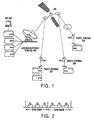
- Fig. 1 is a partially block, partially schematic illustration of a network to which the methods according to the present invention are applied;
- Fig. 2 illustrates the TDMA frame structure for three bursts;
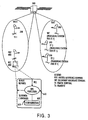
- Fig. 3 illustrates shows a representative spot beam configuration that depicts three designated measuring stations (SRT, TT2, and TT3) for station TT1employed in implementing the uplink power control method according to the present invention;
- Fig. 4 is a flowchart illustrating the steps in a method for dynamically determining the transmit compression point according to the present invention; and
- Fig. 5 is a flowchart illustrating the steps in the uplink power control method according to the present invention.
- As previously mentioned, the methods for performing Uplink Power Control (UPC) in burst mode satellite/wireless networks rely on measurement of transmitter (uplink) link quality at multiple receiver (downlink) nodes in the distributed network. The link quality measurements are transferred to a central Network Control Center (NCC) computer, which computer implements a novel method for iteratively adjusting the transmit power on a per-burst basis to thereby achieve improved target link quality. This method features optimal response loop time constants to compensate for fast weather induced uplink fades as well as slow degradations in transmit amplifier power due to temperature variations and aging. Moreover, the NCC computer employs an additional method to dynamically detect the transmit power amplifier compression point and ensure sufficient input-back-off (IBO) under all conditions.
- Fig. 1 illustrates a model of the network architecture employing the novel methods according to the present invention. A network consists of a set of terminals, including a plurality of
traffic terminals 200 connected to amaster reference terminal 400, which is under control of a network control center (NCC) 600, via asatellite 300. It will be appreciated that the network depicted in Fig. 1 is only one of a myriad of possible network configurations and that all such network configurations are considered be included with the scope of the present invention. The methods implemented viaNCC 600 work in a distributed environment;multiple terminals 200 act as measuring stations and theNCC 600 implements the primary UPC method based on feedback reports from thevarious terminals 200. - It should be mentioned that the network depicted in Fig. 1 employs the Time Division Multiple Access (TDMA) technique to access satellite capacity, i.e., time is divided using a framing structure. A frame is a fixed period of time, with some way to identify the start and end of that time period. A frame contains bursts. Such a framing structure is commonly used in TDMA satellite networks. In satellite networks, frames are usually of the order of milliseconds. It will be appreciated that terrestrial networks also have framing structures, e.g., e.g., for T1 or E1 framing, etc.
- Fig. 2 illustrates the TDMA frame structure with three bursts B1, B2 and B3. It will be appreciated that TDMA operates according to the following general rules:
- 1. Data is transmitted on the channels, which are contained in bursts.
- 2. Each burst is defined at a fixed offset (henceforth referred to as a burst offset) relative to a start of frame (SOF) instant.
- 3. The network uses a pool of radio frequency (RF) carriers at different frequencies.
- 4. A burst is allocated on a carrier.
- 5. Bursts on the same carrier cannot overlap in time. Bursts on different carriers may, however, overlap in time.
- 6. Carriers are subdivided into slots. No two bursts can begin in the same slot in one carrier (burst offsets should fall in different slots).
- 7. Bursts are allocated among modems, wherein the term "modem" or "terminal" is henceforth used to denote the earth station which transmits or receives a burst.
- It should also be mentioned that in the network illustrated in Fig. 1, it is assumed that the terminal that transmits, e.g.,
MRT 400, a burst knows the offset of the burst relative to the start of frame, the carrier frequency, and the power level. On the receive side, the terminal, e.g.,TT 200, tunes to the corresponding carrier frequency and extracts the burst knowing the approximate position in time. Every terminal has a reliable control channel to and from theNCC 600, implemented using data channels within special bursts. Thus, theNCC 600 andterminals - Moreover, bursts are addressed to and from terminals. A burst can be modulated using Quadrature Phase Shift Keying (QPSK) or Binary Phase Shift Keying (BPSK) techniques. BPSK gives a 3 dB improvement in performance over QPSK, but uses twice the number of symbols in a TDMA frame for the same information content. In a typical network, the modulator output level can be varied between -15 dBm and -5 dBm in 0.5 dB steps. Typically, a higher modulator output level produces a higher power out of the transmit RF power amplifier.
- The quality of a terminal's uplink transmission is measured on multiple downlink receivers by using the raw link bit error rate (BER). It will be noted that every burst is encoded using a convolution forward error correction code (FEC). The FEC decoder in a terminal 200/400 provides an accurate estimate of the BER for a received burst before any error correction is performed. All terminals in the network periodically transmit a special burst referred to as a Control Burst (CB) which is primarily used to maintain terminal transmit synchronization. The CB is visible on the downlink to several terminals in the corresponding spot or beam, including a Reference Terminal (RT). Thus, for every transmitting terminal, a BER measurement indicating link quality is made at multiple downlink terminals.
- It should be mentioned at this point that the UPC method according to the present invention does not require that every terminal in the network perform measurements on every transmitter visible to them. The
NCC 600 advantageously determines a set of measuring stations and commands selected terminals to perform measurements. Fig. 3 illustrates a representative spot beam configuration that depicts three designated measuring stations (SRT, TT2, and TT3) for station TT1. It should be mentioned that the use of multiple measuring stations works uniformly in global, hemispherical, and spot beam environments. The TDMA network architecture includes a timing and control scheme that works in all beam configurations. Thus, for every transmitter, multiple observers advantageously can be found. - Every measuring terminal computes BER on all bursts received by it, including a Reference Burst (RB) transmitted by the
MRT 400 and the CB transmitted bydifferent traffic terminals 200. The measuring terminal generates a downlink fade tag by examining the BER on all bursts received (including the RB) and determining if a majority of them, including the RB, are degraded. Every measuring terminal sends the CB BER measurement for each transmitting traffic terminal to theNCC 600 along with the tag indicating downlink fade. It is important to correctly attribute an overall change in link quality to either transmit impairments or downlink degradations. TheNCC 600 uses the downlink fade tag to select CB BER measurements for further processing according to the UPC method. - The
NCC 600 maintains a configuration database for every terminal. Items in this database include amplifier characteristics, location, rain zone information, link propagation data, reference power-BER characteristics, threshold values for BER, and threshold values for downlink impairment detection. Amplifier data includes the minimum IBO that meets output spectral specifications. It will be appreciated from Fig. 3 thatNCC 600 advantageously includes aUPC controller 610 coupled to amemory 620 storing the configuration database. - The
NCC 600 uses transmit power as the primary means to adjust link quality. Optionally, the modulation scheme (BPSK/QPSK) and burst FEC coding rate can be changed to extend the range of link quality improvement. More specifically, theNCC 600 performs the following method to dynamically detect transmit amplifier compression and derive a transmit power adjustment on a burst-by-burst basis for every terminal. - The method for dynamically determining the transmit compression point according to the present invention will now be described while referring to Fig. 4. It will be appreciated that the 1 dB compression of the amplifier, e.g., the amplifier in
MRT 400, is referred to by P1, which is defined as the input power level at which the output power is 1 dB below the linear scale at 25° Celsius. In short, P1 is located just under the saturation level of the amplifier operating at standard conditions. - It will be appreciated that the terminal normally transmits all bursts, including the CB, at a power level set by the
NCC 600. Periodically, e.g., once in 30 minutes although other periods are possible, the terminal transmits the CB calibration sequence at power levels H, M, and L for several frames. On the downlink, the BER for all received bursts is computed and for CB BER, the corresponding transmit power setting indicated in the CB data is extracted at the receive terminal. The CB BER is then reported to theNCC 600 with a transmit power indication and the downlink fade tag described previously. - As illustrated in Fig. 4, during
Step 100, the terminal periodically implements the CB calibration sequence. In this sequence, the terminal transmits the CB at three different power levels: high power level H; medium power level M; and low power level L, frame to frame. It will be appreciated that the CB includes data on the transmit power used. Initially, H = P1- h dB, M = P1 - m dB and L = P1 - 1 dB, where typical values for h, m, and 1 are 1, 2, and 3 dB, respectively. It will also be appreciated that these values are maintained in theNCC 600 configuration database. - During
Step 101, each receiver tags the CB BER measurement with the transmit power indicated and transmit this information toNCC 600 duringStep 102. TheNCC 600 computes the average BER for all CBs from a terminal at H, M, and L power levels atStep 103. Then, the BER slope is computed for levels H to M, M to L, and H to L duringStep 104. - During
Step 105, a check is performed to determine whether the BER slopes track reference power-BER data. When the BER difference scales corresponding to the power difference, i.e., all BER slopes are tracking the reference power-BER data, the amplifier transmit characteristics are normal and not shifted. The method jumps back toStep 100. However, when the BER indicates less increase in performance with increased power, i.e., lower slope at higher power levels, the terminal is approaching saturation. In this latter case, the maximum power allowed, P, for the terminal is set at level M atStep 106. Normally, the maximum power level allowed is set at H. The method then jumps back to the start ofStep 100. - The UPC method according to the present invention is illustrated in Fig. 5. During
Step 110, theNCC 600 examines CB BER measurement reports for each transmittingterminal 200, i.e., SRT, TT 2 and TT 3 as illustrated in Fig. 3, and computes the average of BER measurements from a sub-set of measuring terminals with unfaded downlinks during Step 111. This set is derived from the earth station configuration as an ordered set based on antenna size, starting with the smallest. It should be noted that terminals marked in the configuration database as located in a low rain zone region and with high stability downlink chain are preferred measurement terminals. Measurements from terminals with the smallest antenna size have the best sensitivity to uplink impairments, especially when the measuring terminal downlink is not degraded. It should also be noted that typical networks are uplink power limited. Terminals with large receive gain or antenna size are less representative of a majority of the terminals in the network and less susceptible to impairments in a power limited transmitter. - A check is then performed at
Step 112 to determine whether the average BER is greater than a predetermined BER threshold. When the average BER is greater than threshold BER, transmit power is increased by U dB atStep 113; when the average BER is less than threshold BER, transmit power is decreased by D dB atstep 117. Step sizes U and D are determined based on the difference between the measured BER and target BER and maintained in a data table in the NCC configuration database. It will be appreciated that this UPC method according to the present invention provides a fast response to uplink rain fade events and slow response to other time/temperature dependent degradations. - Furthermore, as mentioned previously, the TX power is limited to P, based on the compression point of the transmitter. A check is then performed at
Step 114 to determine if transmit power is greater than maximum power level P. When the average BER is greater than the threshold BER even at maximum power level P, the terminal is marked as preferring BPSK modulation for the bursts during step 115. The method then returns to the beginning ofStep 110. When the average BER is less than the threshold BER, the terminal is marked as preferring QPSK modulation for the bursts. The method then returns to the beginning ofStep 110. Advantageously, theNCC 600 allocates bursts of the preferred modulation type subject to frame space availability and traffic priorities. - Although presently preferred embodiments of the present invention have been described in detail hereinabove, it should be clearly understood that many variations and/or modifications fall within the scope of the present invention, as defined in the appended claims.
Claims (9)
- A method for dynamically determining the power compression point of an amplifier in a distributed network under the control of a computer, the network having a first terminal including the amplifier operatively coupled to a plurality of second terminals by a communication channel for transmitting signals from the first terminal to the second terminals, said method comprising steps for:generating bit error rate (BER) messages indicative of measured BER for a signal transmitted at N power levels, where N is a positive integer, said BER messages including respective tags indicative of the N power levels for that BER, at the second terminals;determining whether the amplifier is approaching saturation on the basis of the BER messages; andreducing the maximum allowed power of the amplifier when it is determined that the amplifier is approaching saturation responsive to the BER messages.
- The method as recited in claim 1, wherein N is an integer greater than 2, and wherein said reducing step comprises steps for:determining an average BER responsive to said BER messages;determining BER slope responsive to said average BER; andreducing the maximum allowed power when the BER slope is indicative of lower slope at higher power levels.
- The method as recited in claim 1, wherein the signal is a control burst.
- The method as recited in claim 3, wherein the control burst is transmitted at the N power levels is N sequential frames, and wherein N is an integer greater than or equal to 2.
- The method recited in claim 1, further comprising:(1) transmitting a signal at N power levels to the second terminals, where N is a positive integer;(2) measuring a bit error rate (BER) for each of said N power levels at the second terminals;(3) transmitting the BER messages to the computer.
- The method as recited in claim 5, wherein the signal is a control burst, and wherein the communications channel comprises a satellite.
- The method as recited in claim 6, wherein the control burst is transmitted at N power levels is N sequential frames, and wherein N is an integer greater than or equal to 2.
- The method as recited in claim 5, wherein said determining step (5) further comprises steps of:determining an average BER responsive to said BER messages; anddetermining BER slope responsive to said average BER; andsaid reducing step further comprises reducing the maximum allowed power when the BER slope is indicative of lower slope at higher power levels.
- The method as recited in claim 5, wherein said determining step (5) further comprises steps of:determining an average BER responsive to said BER messages; anddetermining BER slope responsive to said average BER; andevaluating the BER slope with respect to reference power-BER data stored in the computer; andsaid reducing step further comprises reducing the maximum allowed power when the BER slope and said reference power-BER data diverge to thereby indicate a lower slope at higher power levels.
Applications Claiming Priority (7)
| Application Number | Priority Date | Filing Date | Title |
|---|---|---|---|
| US6249797P | 1997-10-20 | 1997-10-20 | |
| US6467397P | 1997-10-20 | 1997-10-20 | |
| US6249697P | 1997-10-20 | 1997-10-20 | |
| US62496P | 1997-10-20 | ||
| US64673P | 1997-10-20 | ||
| US62497P | 1997-10-20 | ||
| PCT/US1998/021632 WO1999021378A1 (en) | 1997-10-20 | 1998-10-20 | A method for uplink power control for distributed satellite networks to compensate for rain fade |
Publications (3)
| Publication Number | Publication Date |
|---|---|
| EP1042932A1 EP1042932A1 (en) | 2000-10-11 |
| EP1042932A4 EP1042932A4 (en) | 2001-01-31 |
| EP1042932B1 true EP1042932B1 (en) | 2006-01-11 |
Family
ID=27370308
Family Applications (6)
| Application Number | Title | Priority Date | Filing Date |
|---|---|---|---|
| EP98954967A Withdrawn EP1044513A4 (en) | 1997-10-20 | 1998-10-20 | Power output control system for rf communications system |
| EP98953469A Expired - Lifetime EP1042932B1 (en) | 1997-10-20 | 1998-10-20 | A method for uplink power control for distributed satellite networks to compensate for rain fade |
| EP98951081A Expired - Lifetime EP1032986B1 (en) | 1997-10-20 | 1998-10-20 | Method for transmission of circuit switched data, packet data, and atm cell data in a satellite/wireless tdma system |
| EP98956107A Expired - Lifetime EP0960489B1 (en) | 1997-10-20 | 1998-10-20 | A method for generation of accurate doppler-free local clock in a satellite or wireless network |
| EP98956116.2A Expired - Lifetime EP0960490B1 (en) | 1997-10-20 | 1998-10-20 | Method for acquisition and synchronization of terminals in a wireless tdma system |
| EP98953472A Expired - Lifetime EP1025653B1 (en) | 1997-10-20 | 1998-10-20 | Method for measurement and reduction of frequency offsets in distributwed satellite/wireless networks and corresponding communications system |
Family Applications Before (1)
| Application Number | Title | Priority Date | Filing Date |
|---|---|---|---|
| EP98954967A Withdrawn EP1044513A4 (en) | 1997-10-20 | 1998-10-20 | Power output control system for rf communications system |
Family Applications After (4)
| Application Number | Title | Priority Date | Filing Date |
|---|---|---|---|
| EP98951081A Expired - Lifetime EP1032986B1 (en) | 1997-10-20 | 1998-10-20 | Method for transmission of circuit switched data, packet data, and atm cell data in a satellite/wireless tdma system |
| EP98956107A Expired - Lifetime EP0960489B1 (en) | 1997-10-20 | 1998-10-20 | A method for generation of accurate doppler-free local clock in a satellite or wireless network |
| EP98956116.2A Expired - Lifetime EP0960490B1 (en) | 1997-10-20 | 1998-10-20 | Method for acquisition and synchronization of terminals in a wireless tdma system |
| EP98953472A Expired - Lifetime EP1025653B1 (en) | 1997-10-20 | 1998-10-20 | Method for measurement and reduction of frequency offsets in distributwed satellite/wireless networks and corresponding communications system |
Country Status (8)
| Country | Link |
|---|---|
| US (2) | US7599658B1 (en) |
| EP (6) | EP1044513A4 (en) |
| JP (2) | JP3390180B2 (en) |
| AU (8) | AU1270499A (en) |
| CA (3) | CA2275406C (en) |
| DE (4) | DE69814448T2 (en) |
| IL (8) | IL130559A (en) |
| WO (8) | WO1999021329A1 (en) |
Families Citing this family (46)
| Publication number | Priority date | Publication date | Assignee | Title |
|---|---|---|---|---|
| US7215650B1 (en) | 1999-08-16 | 2007-05-08 | Viasat, Inc. | Adaptive data rate control for narrowcast networks |
| FR2801747B1 (en) | 1999-11-29 | 2006-09-08 | Cit Alcatel | HIGH AND LOW TRANSMISSION FOR THE REMOTE CONTROL LINK OF A SATELLITE |
| FR2804559A1 (en) * | 2000-02-01 | 2001-08-03 | Sta Satellite Terminal Access | SATELLITE TELECOMMUNICATION METHOD, CORRESPONDING SATELLITE TELECOMMUNICATION TERMINAL |
| KR100657253B1 (en) * | 2000-03-29 | 2006-12-14 | 삼성전자주식회사 | Apparatus for transmitting/receiving wireless packet and method thereof |
| KR100667738B1 (en) | 2000-03-29 | 2007-01-11 | 삼성전자주식회사 | Apparatus for transmitting/receiving wireless packet and method thereof |
| JP3722753B2 (en) * | 2000-03-29 | 2005-11-30 | サムスン エレクトロニクス カンパニー リミテッド | Wireless packet transmitting / receiving apparatus and method |
| EP1275217B1 (en) * | 2000-04-21 | 2012-12-26 | Broadcom Corporation | Performance indicator for a high-speed communication system |
| CN1266909C (en) | 2000-05-25 | 2006-07-26 | 索马网络公司 | Quality dependent data communication channel |
| IL143820A0 (en) * | 2000-06-26 | 2002-04-21 | Hughes Electronics Corp | Uplink power control system for satellite communication system employing on-board satellite processing and fade estimation |
| US7043199B2 (en) | 2001-06-06 | 2006-05-09 | Hughes Network Systems Llc | Uplink power control system for satellite communication system employing on-board satellite processing and fade estimation |
| US7006791B2 (en) | 2001-03-16 | 2006-02-28 | U.S. Monolithics, L.L.C. | System and method for uplink power control by detecting amplifier compression point using dc current detection |
| EP1374447B1 (en) * | 2001-03-16 | 2010-03-03 | U.S. Monolithics, L.L.C. | System and method for uplink power control |
| DE60112035T2 (en) | 2001-03-22 | 2006-05-24 | Siemens Mobile Communications S.P.A. | AUTOMATIC METHOD FOR CONTROLLING THE POWER AND SWITCHING OF THE PHY MODE IN ADAPTIVE PHY MODUS SYSTEMS |
| US7027530B2 (en) * | 2001-04-11 | 2006-04-11 | Atheros Communications, Inc. | Method and apparatus for maximizing receiver performance utilizing mid-packet gain changes |
| US8498368B1 (en) | 2001-04-11 | 2013-07-30 | Qualcomm Incorporated | Method and system for optimizing gain changes by identifying modulation type and rate |
| US7010266B2 (en) | 2001-05-24 | 2006-03-07 | Viasat, Inc. | Power control systems and methods for use in satellite-based data communications systems |
| DE10134764A1 (en) * | 2001-07-13 | 2003-01-30 | Deutsche Telekom Ag | Geostationary satellite management system for efficient use of transponder bandwidth, adapts modulation power and mode automatically, in terms of quality and noise parameters |
| US7941047B2 (en) * | 2001-07-18 | 2011-05-10 | Alcatel-Lucent Usa Inc. | Method for engineering connections in a dynamically reconfigurable photonic switched network |
| EP1309105A1 (en) * | 2001-11-01 | 2003-05-07 | Ascom Systec AG | Dual mode satellite/cellular terminal |
| DE60117750T2 (en) | 2001-12-05 | 2007-02-15 | Siemens Mobile Communications S.P.A. | Optimal hysteresis based on two different transmit power control parameters and PHY mode switching control in adaptive PHY mode systems |
| KR100977077B1 (en) * | 2002-05-29 | 2010-08-19 | 톰슨 라이센싱 | Method and apparatus for enabling transmission of a wireless return channel signal in a satellite communications system |
| US7463707B2 (en) * | 2002-09-03 | 2008-12-09 | Broadcom Corporation | Upstream frequency control for docsis based satellite systems |
| ES2260407T3 (en) * | 2002-09-20 | 2006-11-01 | Siemens S.P.A. | ADJUSTMENT OF THE POWER OF THE ASCENDING LINK, FOR A WIRELESS COMMUNICATION SYSTEM POINT TO MULTIPOINT. |
| US7992174B2 (en) * | 2004-03-29 | 2011-08-02 | Broadcom Corporation | Method and system for downstream time stamp in an adaptive modulation based satellite modem termination system |
| US7974261B2 (en) | 2005-06-13 | 2011-07-05 | Qualcomm Incorporated | Basestation methods and apparatus for supporting timing synchronization |
| US7574224B2 (en) * | 2005-06-13 | 2009-08-11 | Qualcomm Incorporated | Methods and apparatus for performing timing synchronization with base stations |
| US8036205B2 (en) | 2005-06-13 | 2011-10-11 | Qualcomm Incorporated | Methods and apparatus for supporting uplinks with remote base stations |
| US8798638B2 (en) | 2005-07-20 | 2014-08-05 | Qualcomm Incorporated | Methods and apparatus for providing base station position information and using position information to support timing and/or frequency corrections |
| US7991362B2 (en) | 2005-07-20 | 2011-08-02 | Qualcomm Incorporated | Methods and apparatus for supporting timing and/or frequency corrections in a wireless communications system |
| US20070165757A1 (en) * | 2006-01-18 | 2007-07-19 | Arie Heiman | Method and system for an improved cellular interference cancelling diversity receiver |
| US8687744B2 (en) * | 2006-01-18 | 2014-04-01 | Broadcom Corporation | Method and system for an improved cellular diversity receiver |
| US7965664B2 (en) * | 2006-05-31 | 2011-06-21 | Honeywell International Inc. | Apparatus and method for integrating wireless field devices with a wired protocol in a process control system |
| EP2036285B1 (en) * | 2006-06-30 | 2016-08-24 | ViaSat, Inc. | Remote non-linearity detection via burst power dithering |
| JP4974026B2 (en) * | 2007-03-27 | 2012-07-11 | パナソニック株式会社 | Wireless network system |
| US8730086B2 (en) * | 2008-08-26 | 2014-05-20 | Viasat, Inc. | Weather detection using satellite communication signals |
| WO2010148022A1 (en) * | 2009-06-16 | 2010-12-23 | Viasat, Inc. | Dynamic bandwidth resource allocation for satellite downlinks |
| EP2528280B1 (en) | 2010-01-22 | 2017-07-26 | Panasonic Intellectual Property Management Co., Ltd. | Power data collection device, power measurement device, and power data collection method |
| CN101902808B (en) * | 2010-05-21 | 2013-03-06 | 南京邮电大学 | Uplink self-adaptive closed loop power control method for satellite communication system |
| KR101211474B1 (en) | 2011-06-30 | 2012-12-12 | 에이피위성통신주식회사 | Compensation apparatus of error in terminal station of satellite communication system and method thereof |
| US9025516B2 (en) * | 2011-10-13 | 2015-05-05 | Comtech Ef Data Corp. | Method and system for optimizing data throughput performance for dynamic link conditions using adaptive coding and modulation (ACM) and dynamic single channel per carrier (dSCPC) techniques |
| US8787873B1 (en) | 2011-11-04 | 2014-07-22 | Plusn Llc | System and method for communicating using bandwidth on demand |
| CN102638878B (en) * | 2012-03-19 | 2014-06-04 | 西安交通大学 | Distributive beam forming method based on closed loop frequency offset control |
| WO2014016638A1 (en) | 2012-07-24 | 2014-01-30 | Agence Spatiale Européenne | Uplink power control method and apparatus for satellite communications networks |
| CA2814303A1 (en) | 2013-04-26 | 2014-10-26 | Cellphone-Mate, Inc. | Apparatus and methods for radio frequency signal boosters |
| US10367706B2 (en) | 2016-11-21 | 2019-07-30 | At&T Intellectual Property I, L.P. | Automatic identification of solutions for weather-related network impairments |
| US20230412255A1 (en) * | 2020-10-07 | 2023-12-21 | Eutelsat Sa | Method for the compression of data collected by a leo satellite from a plurality of iot devices and the transmission to a base station and associated system |
Family Cites Families (41)
| Publication number | Priority date | Publication date | Assignee | Title |
|---|---|---|---|---|
| US4228538A (en) * | 1977-12-15 | 1980-10-14 | Harris Corporation | Real-time adaptive power control in satellite communications systems |
| US4688216A (en) * | 1984-05-10 | 1987-08-18 | Nec Corporation | Station relief arrangement for use in relieving operation of a reference station in a TDMA network without reduction of frame availability |
| JPS61184014A (en) * | 1985-02-08 | 1986-08-16 | Nec Corp | System and apparatus of initial connection in time division multiple access communciation |
| US4675863A (en) * | 1985-03-20 | 1987-06-23 | International Mobile Machines Corp. | Subscriber RF telephone system for providing multiple speech and/or data signals simultaneously over either a single or a plurality of RF channels |
| US4868795A (en) * | 1985-08-05 | 1989-09-19 | Terra Marine Engineering, Inc. | Power leveling telemetry system |
| JPS6346824A (en) * | 1986-08-14 | 1988-02-27 | Kokusai Denshin Denwa Co Ltd <Kdd> | Transmission power control system |
| US4745599A (en) * | 1987-01-05 | 1988-05-17 | General Electric Company | Random access communication system with contention scheduling of subpacketized data transmissions and scheduled retransmission of unsuccessful subpackets |
| DE3729586A1 (en) * | 1987-09-04 | 1989-03-16 | Ant Nachrichtentech | METHOD FOR COMPENSATING DURING DURATION OF THE BURSTS Caused by the DOPPLER EFFECT IN A TDMA FRAME, AND ARRANGEMENT |
| US4901368A (en) * | 1987-10-19 | 1990-02-13 | American Telephone And Telegraph Company | Frequency translation correction scheme for satellite communication system |
| JP2845889B2 (en) * | 1988-05-16 | 1999-01-13 | 株式会社日立製作所 | Satellite communication system and satellite communication system |
| US4932070A (en) * | 1988-08-22 | 1990-06-05 | Scientific Atlanta | Mechanism for deriving accurate frequency reference for satellite communications burst demodulator |
| JPH02256329A (en) * | 1988-12-01 | 1990-10-17 | Nec Corp | Demodulator control system |
| US4941199A (en) * | 1989-04-06 | 1990-07-10 | Scientific Atlanta | Uplink power control mechanism for maintaining constant output power from satellite transponder |
| JP2746685B2 (en) * | 1989-09-06 | 1998-05-06 | 富士通株式会社 | Transmission output control circuit |
| FI86352C (en) * | 1989-11-14 | 1992-08-10 | Nokia Oy Ab | DIGITALISKT RADIOLAENKSYSTEM OCH FOERFARANDE FOER REGLERING AV EN SAENDINGSEFFEKT I ETT DIGITALISKT RADIOLAENKSYSTEM. |
| US4999583A (en) * | 1990-02-28 | 1991-03-12 | Hughes Aircraft Company | Amplifier drive controller |
| SE467332B (en) * | 1990-06-21 | 1992-06-29 | Ericsson Telefon Ab L M | PROCEDURE FOR POWER CONTROL IN A DIGITAL MOBILE PHONE SYSTEM |
| US5257397A (en) * | 1990-08-13 | 1993-10-26 | At&T Bell Laboratories | Mobile data telephone |
| US5321721A (en) * | 1991-09-13 | 1994-06-14 | Sony Corporation | Spread spectrum communication system and transmitter-receiver |
| DE69231437T2 (en) * | 1991-12-26 | 2001-03-01 | Nec Corp | System for controlling the transmission power with a constant signal quality in a mobile communication network |
| JPH0677963A (en) * | 1992-07-07 | 1994-03-18 | Hitachi Ltd | Communication system and terminal equipment |
| US5465399A (en) * | 1992-08-19 | 1995-11-07 | The Boeing Company | Apparatus and method for controlling transmitted power in a radio network |
| JP2953260B2 (en) * | 1993-07-05 | 1999-09-27 | ケイディディ株式会社 | Frequency offset compensation method |
| US6088590A (en) * | 1993-11-01 | 2000-07-11 | Omnipoint Corporation | Method and system for mobile controlled handoff and link maintenance in spread spectrum communication |
| SE9304119D0 (en) * | 1993-12-10 | 1993-12-10 | Ericsson Ge Mobile Communicat | Devices and mobile stations for providing packaged data communication in digital TDMA cellular systems |
| US5768684A (en) * | 1994-03-04 | 1998-06-16 | Motorola, Inc. | Method and apparatus for bi-directional power control in a digital communication system |
| GB2287371B (en) * | 1994-03-11 | 1998-12-16 | Motorola Israel Ltd | Radio transmitter power amplifier calibration |
| US5659545A (en) * | 1994-11-15 | 1997-08-19 | Motorola, Inc. | Apparatus for mobile unit acquisition in a satellite communication system and method therefor |
| JP3467888B2 (en) * | 1995-02-08 | 2003-11-17 | 三菱電機株式会社 | Receiving device and transmitting / receiving device |
| US5710756A (en) * | 1995-02-13 | 1998-01-20 | Netro Corporation | Burst-error resistant ATM microwave link and network |
| US5732328A (en) * | 1995-04-25 | 1998-03-24 | Lucent Technologies Inc. | Method for power control in wireless networks for communicating multiple information classes |
| US5697056A (en) * | 1995-05-08 | 1997-12-09 | Motorola, Inc. | Communication system in which radio subscriber units mitigate interference |
| US5598419A (en) * | 1995-07-17 | 1997-01-28 | National Semiconductor Corporation | Dynamic synchronization code detection window |
| US5678208A (en) * | 1995-07-19 | 1997-10-14 | Motorola, Inc. | Transmission system |
| EP0779717A3 (en) * | 1995-12-13 | 2000-08-02 | Nec Corporation | Method and system for controlling TDMA timing in satellite communication network |
| US5729536A (en) * | 1996-04-10 | 1998-03-17 | Lucent Technologies | Cellular system architectures supporting data services |
| US5812554A (en) * | 1996-05-28 | 1998-09-22 | Advanced Micro Devices, Inc. | Efficiency of a network having a minimum data transmission time |
| US5864547A (en) * | 1996-08-21 | 1999-01-26 | Hughes Electronics Corporation | Method and system for controlling uplink power in a high data rate satellite communication system employing on-board demodulation and remodulation |
| US5754942A (en) * | 1996-09-09 | 1998-05-19 | Hughes Electronics Corporation | Satellite power level monitoring system and method using digital signal processing |
| US6212360B1 (en) * | 1997-04-09 | 2001-04-03 | Ge Capital Spacenet Services, Inc. | Methods and apparatus for controlling earth-station transmitted power in a VSAT network |
| US5999832A (en) * | 1997-07-31 | 1999-12-07 | Vannatta; Louis J. | Method of and apparatus for controlling a transmit power of a communication device |
-
1998
- 1998-10-20 IL IL13055998A patent/IL130559A/en not_active IP Right Cessation
- 1998-10-20 AU AU12704/99A patent/AU1270499A/en not_active Abandoned
- 1998-10-20 DE DE69814448T patent/DE69814448T2/en not_active Expired - Lifetime
- 1998-10-20 US US09/529,773 patent/US7599658B1/en not_active Expired - Fee Related
- 1998-10-20 DE DE69833217T patent/DE69833217T2/en not_active Expired - Lifetime
- 1998-10-20 AU AU10835/99A patent/AU1083599A/en not_active Abandoned
- 1998-10-20 WO PCT/US1998/021635 patent/WO1999021329A1/en active Application Filing
- 1998-10-20 CA CA002275406A patent/CA2275406C/en not_active Expired - Lifetime
- 1998-10-20 IL IL13578598A patent/IL135785A/en not_active IP Right Cessation
- 1998-10-20 IL IL13578398A patent/IL135783A0/en unknown
- 1998-10-20 EP EP98954967A patent/EP1044513A4/en not_active Withdrawn
- 1998-10-20 DE DE69837614T patent/DE69837614T2/en not_active Expired - Lifetime
- 1998-10-20 AU AU96964/98A patent/AU9696498A/en not_active Abandoned
- 1998-10-20 WO PCT/US1998/022053 patent/WO1999021295A1/en active Application Filing
- 1998-10-20 WO PCT/US1998/021632 patent/WO1999021378A1/en active IP Right Grant
- 1998-10-20 CA CA002275408A patent/CA2275408C/en not_active Expired - Lifetime
- 1998-10-20 WO PCT/US1998/021633 patent/WO1999021291A1/en not_active Application Discontinuation
- 1998-10-20 EP EP98953469A patent/EP1042932B1/en not_active Expired - Lifetime
- 1998-10-20 IL IL13056098A patent/IL130560A/en not_active IP Right Cessation
- 1998-10-20 AU AU10838/99A patent/AU1083899A/en not_active Abandoned
- 1998-10-20 IL IL13578698A patent/IL135786A0/en active IP Right Grant
- 1998-10-20 EP EP98951081A patent/EP1032986B1/en not_active Expired - Lifetime
- 1998-10-20 EP EP98956107A patent/EP0960489B1/en not_active Expired - Lifetime
- 1998-10-20 WO PCT/US1998/021636 patent/WO1999021294A1/en active IP Right Grant
- 1998-10-20 EP EP98956116.2A patent/EP0960490B1/en not_active Expired - Lifetime
- 1998-10-20 IL IL13578498A patent/IL135784A0/en unknown
- 1998-10-20 WO PCT/US1998/022080 patent/WO1999021296A1/en active IP Right Grant
- 1998-10-20 AU AU10837/99A patent/AU1083799A/en not_active Abandoned
- 1998-10-20 AU AU11881/99A patent/AU1188199A/en not_active Abandoned
- 1998-10-20 JP JP52421499A patent/JP3390180B2/en not_active Expired - Lifetime
- 1998-10-20 AU AU10836/99A patent/AU1083699A/en not_active Abandoned
- 1998-10-20 CA CA002306717A patent/CA2306717C/en not_active Expired - Lifetime
- 1998-10-20 DE DE69836798T patent/DE69836798T2/en not_active Expired - Lifetime
- 1998-10-20 EP EP98953472A patent/EP1025653B1/en not_active Expired - Lifetime
- 1998-10-20 WO PCT/US1998/021637 patent/WO1999021290A1/en active IP Right Grant
- 1998-10-20 JP JP11524375A patent/JP2000505993A/en active Pending
- 1998-10-20 AU AU12712/99A patent/AU1271299A/en not_active Abandoned
- 1998-10-20 WO PCT/US1998/021634 patent/WO1999021287A1/en active Application Filing
-
2000
- 2000-04-21 IL IL135783A patent/IL135783A/en not_active IP Right Cessation
- 2000-04-21 IL IL135786A patent/IL135786A/en not_active IP Right Cessation
-
2009
- 2009-04-23 US US12/429,071 patent/US7925211B2/en not_active Expired - Fee Related
Also Published As
Similar Documents
| Publication | Publication Date | Title |
|---|---|---|
| EP1042932B1 (en) | A method for uplink power control for distributed satellite networks to compensate for rain fade | |
| US5511079A (en) | Apparatus and method for controlling forward error correction encoding in a very small aperture terminal | |
| US5893035A (en) | Centralized forward link power control | |
| EP1405461B1 (en) | Signal to noise margin information for power control and bit rate adaptation in ieee 802.11h wlan | |
| CN100362768C (en) | Outer loop/weighted open loop power control in a time division duplex communication system | |
| US6724737B1 (en) | System for controlling communications between a terminal and satellite and method therefore | |
| US5485486A (en) | Method and apparatus for controlling transmission power in a CDMA cellular mobile telephone system | |
| US6978151B2 (en) | Updating path loss estimation for power control and link adaptation in IEEE 802.11h WLAN | |
| US7386321B2 (en) | Base station apparatus and radio communication method | |
| US6073025A (en) | Base station power control during a soft hand-off | |
| KR100355328B1 (en) | Radio communication device and method of controlling transmission rate | |
| US5963870A (en) | Process for switching between IS-95 forward power control and fast forward power control | |
| US7580673B2 (en) | Leader-follower power control | |
| EP0944200A2 (en) | Adaptive modulation method and apparatus | |
| EP1094644A2 (en) | Method and apparatus for controlling transmission power in a CDMA cellular mobile telephone system | |
| US6430394B1 (en) | System for controlling communications between a terminal and satellite and method therefore | |
| KR101123191B1 (en) | A radio communication system, a radio station, and a method of transmitting data | |
| EP0696857A1 (en) | Power control apparatus for use in mobile radio systems | |
| AU7304598A (en) | Method and apparatus for adjusting thresholds and measurements of rec eived signals by anticipating power control commands yet to be executed | |
| US7570967B2 (en) | Method and system of transmission power control | |
| US6760566B1 (en) | Method and apparatus for controlling a transmission power threshold of a satellite communication system | |
| US20070010277A1 (en) | Control device and radio control method | |
| US6331975B1 (en) | User data indicator for discontinuous transmission | |
| WO2001091322A1 (en) | Link adaptation method and quality estimation in a cellular radio system | |
| US6618435B1 (en) | Method for measurement and reduction of frequency offsets in distributed satellite/wireless networks and corresponding communications system |
Legal Events
| Date | Code | Title | Description |
|---|---|---|---|
| PUAI | Public reference made under article 153(3) epc to a published international application that has entered the european phase |
Free format text: ORIGINAL CODE: 0009012 |
|
| 17P | Request for examination filed |
Effective date: 20000508 |
|
| AK | Designated contracting states |
Kind code of ref document: A1 Designated state(s): DE FR GB |
|
| A4 | Supplementary search report drawn up and despatched |
Effective date: 20001218 |
|
| AK | Designated contracting states |
Kind code of ref document: A4 Designated state(s): DE FR GB |
|
| RIC1 | Information provided on ipc code assigned before grant |
Free format text: 7H 04Q 7/20 A, 7H 04B 7/185 B |
|
| RAP1 | Party data changed (applicant data changed or rights of an application transferred) |
Owner name: VIASAT, INC. |
|
| 17Q | First examination report despatched |
Effective date: 20040719 |
|
| GRAP | Despatch of communication of intention to grant a patent |
Free format text: ORIGINAL CODE: EPIDOSNIGR1 |
|
| GRAJ | Information related to disapproval of communication of intention to grant by the applicant or resumption of examination proceedings by the epo deleted |
Free format text: ORIGINAL CODE: EPIDOSDIGR1 |
|
| GRAP | Despatch of communication of intention to grant a patent |
Free format text: ORIGINAL CODE: EPIDOSNIGR1 |
|
| GRAS | Grant fee paid |
Free format text: ORIGINAL CODE: EPIDOSNIGR3 |
|
| GRAA | (expected) grant |
Free format text: ORIGINAL CODE: 0009210 |
|
| AK | Designated contracting states |
Kind code of ref document: B1 Designated state(s): DE FR GB |
|
| REF | Corresponds to: |
Ref document number: 69833217 Country of ref document: DE Date of ref document: 20060406 Kind code of ref document: P |
|
| ET | Fr: translation filed | ||
| PLBE | No opposition filed within time limit |
Free format text: ORIGINAL CODE: 0009261 |
|
| STAA | Information on the status of an ep patent application or granted ep patent |
Free format text: STATUS: NO OPPOSITION FILED WITHIN TIME LIMIT |
|
| 26N | No opposition filed |
Effective date: 20061012 |
|
| REG | Reference to a national code |
Ref country code: FR Ref legal event code: PLFP Year of fee payment: 18 |
|
| REG | Reference to a national code |
Ref country code: FR Ref legal event code: PLFP Year of fee payment: 19 |
|
| REG | Reference to a national code |
Ref country code: FR Ref legal event code: PLFP Year of fee payment: 20 |
|
| PGFP | Annual fee paid to national office [announced via postgrant information from national office to epo] |
Ref country code: FR Payment date: 20171031 Year of fee payment: 20 |
|
| PGFP | Annual fee paid to national office [announced via postgrant information from national office to epo] |
Ref country code: GB Payment date: 20171101 Year of fee payment: 20 |
|
| PGFP | Annual fee paid to national office [announced via postgrant information from national office to epo] |
Ref country code: DE Payment date: 20171229 Year of fee payment: 20 |
|
| REG | Reference to a national code |
Ref country code: DE Ref legal event code: R071 Ref document number: 69833217 Country of ref document: DE |
|
| REG | Reference to a national code |
Ref country code: GB Ref legal event code: PE20 Expiry date: 20181019 |
|
| PG25 | Lapsed in a contracting state [announced via postgrant information from national office to epo] |
Ref country code: GB Free format text: LAPSE BECAUSE OF EXPIRATION OF PROTECTION Effective date: 20181019 |
|
| P01 | Opt-out of the competence of the unified patent court (upc) registered |
Effective date: 20230529 |