EP1042554B1 - Removable doctor blade holder - Google Patents
Removable doctor blade holder Download PDFInfo
- Publication number
- EP1042554B1 EP1042554B1 EP98963263A EP98963263A EP1042554B1 EP 1042554 B1 EP1042554 B1 EP 1042554B1 EP 98963263 A EP98963263 A EP 98963263A EP 98963263 A EP98963263 A EP 98963263A EP 1042554 B1 EP1042554 B1 EP 1042554B1
- Authority
- EP
- European Patent Office
- Prior art keywords
- doctor
- blade holder
- roll
- blade
- machine direction
- Prior art date
- Legal status (The legal status is an assumption and is not a legal conclusion. Google has not performed a legal analysis and makes no representation as to the accuracy of the status listed.)
- Expired - Lifetime
Links
- 239000012530 fluid Substances 0.000 claims description 2
- 238000012423 maintenance Methods 0.000 description 7
- 238000004140 cleaning Methods 0.000 description 6
- 238000009434 installation Methods 0.000 description 2
- 230000008439 repair process Effects 0.000 description 2
- 238000000605 extraction Methods 0.000 description 1
- 238000003780 insertion Methods 0.000 description 1
- 230000037431 insertion Effects 0.000 description 1
- 238000007689 inspection Methods 0.000 description 1
- 230000004048 modification Effects 0.000 description 1
- 238000012986 modification Methods 0.000 description 1
- 238000000926 separation method Methods 0.000 description 1
Images


Classifications
-
- D—TEXTILES; PAPER
- D21—PAPER-MAKING; PRODUCTION OF CELLULOSE
- D21G—CALENDERS; ACCESSORIES FOR PAPER-MAKING MACHINES
- D21G3/00—Doctors
- D21G3/005—Doctor knifes
Definitions
- This invention relates generally to doctors used in papermaking machines, and is concerned in particular with the provision of a blade holder which is readily separable from the doctor back and removable from the papermaking machine for cleaning, inspection and repair.
- the main components of a doctor system include the doctor blade, the blade holder, the doctor back and the loading mechanism.
- the doctor blade keeps the roll clean and/or sheds the sheet. It must be perfectly flat, straight and parallel, and its composition must be compatible with the roll to be doctored.
- the blade holder exerts a uniform, designated load pressure on the blade. It holds the blade firmly against the roll, accommodates roll irregularities and, within limits, compensates for thermal expansion.
- the doctor back is in essence the backbone of the doctor. It serves as the support structure for the blade holder.
- the loading mechanism pivots the doctor back to load the doctor blade against the roll.
- doctor blade holder designs used in recent years are more complex and have more components than the simpler blade holders used in the past. As a result, the more recent holder designs require more routine cleaning and maintenance.
- the doctor blade holders are normally mounted to the doctor back rigidly with a series of fasteners. Maintenance and cleaning of the blade holder can take place while the doctor remains in the machine but only in installations where the holder is accessible.
- papermachine framework or other equipment prevents access to the blade holder while it is in the papermachine.
- the complete doctor structure including the doctor back and attached holder must be removed from the papermachine to perform any cleaning or maintenance work. This task involves removing heavy equipment which requires extensive manpower and machine downtime. After making the necessary repairs, the entire doctor assembly must be re-installed in the papermachine, consuming more valuable manpower and time. In addition to the re-installation, the doctor must be realigned to the roll surface for optimum doctor performance.
- the present invention relates to apparatus for doctoring a roll rotatably mounted in a papermachine for rotation about an axis extending in a cross-machine direction, said apparatus comprising a doctor blade, a blade holder for applying said doctor blade to the surface of said roll, and a doctor back for supporting the blade holder, said blade holder including: support means for supporting said doctor blade on a support tray for pivotal movement about another axis parallel to the rotational axis of said roll.
- the support means are components of an integral assembly provided with mounting means for removably mounting said integral assembly on said doctor back in an operative position adjacent said roll and extending in said cross-machine direction; and with locking means for releasably securing said integral assembly in said operative position, said locking means being accessible and operable from a side of said papermachine.
- a doctor assembly in accordance with the present invention is generally depicted at 10 adjacent to a papermachine roll 12.
- Roll 12 is driven by conventional means (not shown) for rotation about an axis A 1 extending in the cross-machine direction.
- the doctor assembly includes a doctor blade 14, a blade holder 16, a doctor back 18, and a loading mechanism 20.
- the doctor back is mounted on the papermachine frame for pivotal movement about an axis A 2 extending in the cross-machine direction parallel to the rotational axis A 1 of roll 12.
- the loading mechanism 20 includes a piston-cylinder unit 22 acting through lever arm 24 to pivot the doctor back 18 about its axis A 2 in order to load the doctor blade 14 against the surface of the roll 12.
- the blade holder 16 includes a tray 26 with upstanding brackets 28 located between an unloading tube 30 and a loading tube 32.
- a top pressure plate 34 overlies the tubes 30, 32 and has depending brackets 36 which are connected to the brackets 28 by a rod 38 for pivotal movement about a third axis A 3 parallel to axes A 1 and A 2 .
- Fingers 40 cooperate with the underside of the top pressure plate 34 to retain the doctor blade 14 in its forwardly extending position.
- the tubes 30, 32 are fluid actuated, with tube 32 serving to coact with the force being applied by the loading mechanism 20 to apply the blade 14 to the surface of the roll 12.
- Tube 30 serves to unload the blade from the roll surface, in addition to acting as a front seal.
- a pair of L-shaped confronting mounting strips 42a, 42b are secured to the underside of the tray 26.
- the mounting strips have horizontal ledges 44a, 44b spaced one from the other to define a continuous slot 46 communicating with an interior recess 47.
- a shelf 50 extends forwardly from and forms an integral part of the doctor back 18. Shoulder screws 52 are threaded into the shelf 50 at spaced locations along the length of the slot 46.
- a locking strip 54 in interposed between the ledges 44a, 44b and the heads of the shoulder screws 52. The locking strip is slotted as at 56 to accommodate the shoulder screws, and the slots 56 are partially bordered by resilient tabs 58 which are bent upwardly out of the plane of the locking strip.
- the locking strip 54 is slidable longitudinally with respect to the shelf 50 of the doctor back and the mounting strips 42a, 42b on the underside of the tray 26.
- the tabs 58 are deflected downwardly by the heads of the shoulder screws 52 into the plane of the strip 54, thereby exerting a downward force which clamps the ledges 44a, 44b against the shelf 50, thus fixing the doctor holder 16 in its operative position on the doctor back 18.
- a pin 60 or the like at one side of the papermachine is employed to releasably fix the locking strip 54 in its locked position.
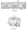
- the pin 60 When it becomes necessary to clean or maintain the blade holder, the pin 60 is removed and the locking strip 54 is shifted to its unlocked position as shown in Figure 3B. This relieves the clamping force exerted by the resilient tabs 58, thus allowing the blade holder and doctor blade to be extracted longitudinally as a unit out of the papermachine. After cleaning and maintenance, the blade holder is longitudinally reinserted into the papermachine, and the clamping strip returned to its locked position.
- FIG. 4 An alternative embodiment of the invention is depicted in Figures 4 and 5, where a mounting strip 62a is secured to the underside of the tray 26.
- a second mounting strip 62b is connected to strip 62a by means of shoulder screws 64 extending through angled slots 66.
- the strips 62a, 62b coact to define a dovetailed slot 68 for receiving a dovetail strip 70 secured to the doctor back shelf 50 by screws 72.
- Longitudinal movement of the strip 62b in direction A will urge it laterally against the dovetail strip 70, thus clamping the blade holder in place.
- Longitudinal movement of the strip 62b in the opposite direction B will shift the strip 62b laterally away from strip 70, thus freeing the doctor holder for removal from the doctor back.
- the blade holder can be slid longitudinally into and out of its operative position, whereas a more pronounced lateral shifting of the strip will permit the blade holder to be lifted from and lowered onto the doctor back.
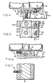
- a male dovetail strip 74 is secured to the underside of the tray 26 and a female dovetail strip 76 is secured to the doctor back shelf 50.
- a set screw 78 at one side of the papermaking machine serves to fix male dovetail the strip 74 against sliding movement relative to the female dovetail strip 76.
- the screw 78 is backed off as shown in Figure 7, the blade holder is free to slide longitudinally into and out of its operative position on the doctor back.
- a female dovetail strip 80 is secured to the underside of the tray 26, and frustoconical dovetail washers 82 are secured to and spaced along the length of the doctor back shelf 50.
- stepped washers 84 are secured at spaced locations along the underside of the tray 26, and a mounting strip 86 is secured to the doctor back shelf 50.
- the mounting strip 86 has an undercut channel 88 along which the stepped washers slide during longitudinal extraction and insertion of the blade holder.
- Figure 12 illustrates another embodiment where a mounting strip 90 with an undercut channel 92 is secured to the doctor back shelf 50.
- the channel 92 is interrupted as at 94 at spaced locations along its length. This allows either the stepped washers 84 of Figures 11 or 12 stepped strip segments 96 which are secured to the underside of the blade holder tray 26 to slide along the channel 92 to positions at which they may exit via the interrupted sections 94 either laterally in direction A or vertically in direction B.
- a locking means of some type is provided at one side of the machine to prevent removal of the blade holder from the doctor back during operation of the papermachine.
- locking can be achieved by providing a bracket 98 on the tray 26 at one side of the papermachine which is detachably connected to the doctor back shelf 50 by a pin 100 or the like.
- the present invention provides for ready separation of the doctor blade holder from the doctor back for removal from the papermachine.
- the embodiments illustrated in Figure 1-5 provide means for securely clamping the blade holder to the doctor back during operation of the papermachine.
- Other embodiments as illustrated in Figures 6-13 lock the blade holder in its operative position, but do not exert additional clamping forces. All arrangements are advantageous in that removability of the blade holder provides maintenance personnel with the opportunity to clean and perform maintenance outside of the papermachine, without disturbing the doctor back.
Landscapes
- Paper (AREA)
- Coating Apparatus (AREA)
- Details Of Cutting Devices (AREA)
Description
Claims (9)
- Apparatus (10) for doctoring a roll (12) rotatably mounted in a papermachine for rotation about an axis (A1) extending in a cross-machine direction, said apparatus comprising a doctor blade (14), a blade holder (16) for applying said doctor blade to the surface of said roll, and a doctor back (18) for supporting the blade holder, said blade holder including: support means (26, 34, 40, 28, 36, 38) for supporting said doctor blade for pivotal movement about another axis (A3) parallel to the rotational axis (A1) of said roll; characterized in that said support means are components of an integral assembly provided with mounting means (42a, 42b, 52, 54; 62a, 62b, 70, 72; 74, 76; 80, 82; 84, 86; 90, 96) for removably mounting said integral assembly on said doctor back (18) in an operative position adjacent said roll and extending in said cross-machine direction; and with locking means (60; 78; 98, 100) for releasably securing said integral assembly in said operative position, said locking means being accessible and operable from a side of said papermachine.
- Apparatus according to claim 1, wherein said blade holder (16) is moveable into and out of said operative position in said cross-machine direction.
- Apparatus according to claim 1, wherein said blade holder (16) is moveable into and out of said operative position in a direction transverse to said cross-machine direction.
- Apparatus according to claim 1, wherein said mounting means comprises mechanically internegageable components (42a, 42b, 54, 62a, 70, 76, 74, 80, 82, 86, 84), at least one of said components extending longitudinally in said cross-machine direction.
- Apparatus according to claim 4, wherein said interengageable components (42a, 42b, 54, 62a, 70, 74, 76) each extend coextensively in said cross-machine direction.
- Apparatus as claimed in claim 5, wherein said interengageable components include a slidable element (54).
- Apparatus according to any one or more of claims 1 to 6, wherein the locking means takes the form of pins or screws (60, 78, 100).
- Apparatus according to any one or more of claims 1 to 7, wherein the support means includes a pressure plate (34) and fingers (40) with the doctor blade (14) disposed between the pressure plate (34) and the fingers (40).
- Apparatus according to claim 8 wherein the support means includes a support tray (26) with fluid actuated loading means (30, 32) arranged in said support tray (26) on opposite sides of said other axis (A3) for pivotally adjusting said pressure plate to forcibly apply said doctor blade to said roll.
Applications Claiming Priority (5)
| Application Number | Priority Date | Filing Date | Title |
|---|---|---|---|
| US210566 | 1980-11-26 | ||
| US6846397P | 1997-12-22 | 1997-12-22 | |
| US68463P | 1997-12-22 | ||
| US09/210,566 US5980692A (en) | 1997-12-22 | 1998-12-14 | Removable doctor blade holder |
| PCT/US1998/026954 WO1999032717A1 (en) | 1997-12-22 | 1998-12-18 | Removable doctor blade holder |
Publications (2)
| Publication Number | Publication Date |
|---|---|
| EP1042554A1 EP1042554A1 (en) | 2000-10-11 |
| EP1042554B1 true EP1042554B1 (en) | 2003-03-12 |
Family
ID=26749004
Family Applications (1)
| Application Number | Title | Priority Date | Filing Date |
|---|---|---|---|
| EP98963263A Expired - Lifetime EP1042554B1 (en) | 1997-12-22 | 1998-12-18 | Removable doctor blade holder |
Country Status (8)
| Country | Link |
|---|---|
| US (1) | US5980692A (en) |
| EP (1) | EP1042554B1 (en) |
| JP (1) | JP3382223B2 (en) |
| BR (1) | BR9814401A (en) |
| CA (1) | CA2314070C (en) |
| DE (1) | DE69812174T2 (en) |
| ES (1) | ES2193600T3 (en) |
| WO (1) | WO1999032717A1 (en) |
Cited By (2)
| Publication number | Priority date | Publication date | Assignee | Title |
|---|---|---|---|---|
| EP2169114A4 (en) * | 2007-07-11 | 2013-11-20 | Azcolain Jose Joaquin Amonarriz | Scraping apparatus for the paper industry |
| CN107287970A (en) * | 2016-04-12 | 2017-10-24 | 河北永新纸业有限公司 | A kind of paper hair and sicker removing device |
Families Citing this family (25)
| Publication number | Priority date | Publication date | Assignee | Title |
|---|---|---|---|---|
| US6312563B1 (en) * | 1997-12-22 | 2001-11-06 | Thermo Web Systems, Inc. | Removable doctor blade holder |
| FI108654B (en) * | 1999-04-15 | 2002-02-28 | Metso Paper Inc | Load arrangement for paper machine makers |
| CA2374786A1 (en) | 1999-05-25 | 2000-11-30 | John Moscone | Doctor blade extractor |
| US6202252B1 (en) * | 1999-06-03 | 2001-03-20 | Valmet Ltd. | Doctoring apparatus |
| US6491754B1 (en) * | 2000-06-13 | 2002-12-10 | Voith Sulzer Paper Technology North America, Inc. | Carbon fiber doctor blade |
| US6524444B2 (en) * | 2001-04-24 | 2003-02-25 | Kadant Web Systems Inc. | Removable doctor blade holder |
| AT412732B (en) * | 2003-10-13 | 2005-06-27 | Bartelmuss Klaus Ing | DEVICE FOR CLEANING A ROLLER IN A PAPER PRODUCTION PLANT |
| WO2006091427A1 (en) * | 2005-02-22 | 2006-08-31 | Kadant Web Systems, Inc. | Removable doctor blade holder with lockable mount |
| WO2007090045A1 (en) * | 2006-01-31 | 2007-08-09 | Kadant Inc. | Keep for doctor blade holder |
| WO2008022096A1 (en) * | 2006-08-16 | 2008-02-21 | Kadant Web Systems, Inc. | Doctor blade holder permitting efficient assembly of doctor assemblies and replacement of doctor blades |
| JP4890210B2 (en) * | 2006-11-24 | 2012-03-07 | 株式会社ドクター製作所 | Doctor device doctor blade mounting method, blade insertion groove cleaning method, and cleaning blade |
| SE532221C2 (en) * | 2007-02-22 | 2009-11-17 | Cs Produktion Ab | Apparatus and method for creping paper |
| FI119823B (en) * | 2007-10-10 | 2009-03-31 | Metso Paper Inc | Creator equipment and method for a sheet forming machine for scraping a moving surface and blade holder |
| EP2055481B1 (en) * | 2007-10-18 | 2017-08-16 | Bobst Italia S.P.A. | Doctor blade assembly and a method for allowing different inks to be used |
| ES2368881T3 (en) * | 2007-12-06 | 2011-11-23 | Kadant Inc. | KNIFE HOLDER |
| FI121390B (en) * | 2009-03-31 | 2010-10-29 | Runtech Systems Oy | Paper machine maker and method for streamlining maintenance of a paper machine shaver |
| JP2012158840A (en) * | 2011-01-31 | 2012-08-23 | Doctor Manufacturing Co Ltd | Doctor device |
| SE539141C2 (en) * | 2015-11-13 | 2017-04-18 | Valmet Oy | Doctor arrangement for a disc filter |
| CN112770944B (en) | 2018-09-05 | 2023-12-22 | 阪东化学株式会社 | Scraper installation tools and scraper support structure |
| US12508597B2 (en) | 2021-03-10 | 2025-12-30 | Metso Usa Inc. | Spur wheel scraper |
| US20240082849A1 (en) * | 2022-09-08 | 2024-03-14 | Metso Outotec USA Inc. | Roller crusher and a method for operating the same |
| EP4343060A3 (en) * | 2022-09-23 | 2024-05-01 | Valmet Technologies Oy | Stud for a doctor blade holder in a fiber web machine and doctor blade holder assembly for a fiber web machine |
| FI131234B1 (en) * | 2022-09-23 | 2024-12-19 | Valmet Technologies Oy | Stud for a doctor blade holder in a fiber web machine and doctor blade holder assembly for a fiber web machine |
| US12508595B2 (en) | 2023-06-07 | 2025-12-30 | Metso Usa Inc. | Roller crusher and a method for operating the same |
| US12508598B2 (en) | 2023-06-07 | 2025-12-30 | Metso Usa Inc. | Roller crusher and method for operation thereof |
Family Cites Families (15)
| Publication number | Priority date | Publication date | Assignee | Title |
|---|---|---|---|---|
| US1696119A (en) * | 1927-03-07 | 1928-12-18 | Mead Pulp & Paper Company | Paper machinery |
| US3645844A (en) * | 1968-04-22 | 1972-02-29 | Lodding Engineering Corp | Mounting means for foil type and similar elements |
| US3593663A (en) * | 1969-06-03 | 1971-07-20 | Zerand Corp | Doctor blade assembly for printing equipment |
| US3780670A (en) * | 1972-08-07 | 1973-12-25 | Faustel Inc | Doctor blade assembly |
| US3854162A (en) * | 1973-03-02 | 1974-12-17 | Bird Machine Co | Doctor blade holder |
| US4241691A (en) * | 1978-08-30 | 1980-12-30 | Monsanto Company | Doctor blade holder |
| US4459176A (en) * | 1982-11-12 | 1984-07-10 | Thermo Electron Corporation | Dewatering system with adjustable width suction slots |
| US4665859A (en) * | 1985-12-11 | 1987-05-19 | Thermo Electron-Web Systems, Inc. | Finger-type doctor blade holder |
| US4789432A (en) * | 1987-06-08 | 1988-12-06 | Thermo Electron Web Systems, Inc. | Doctoring apparatus |
| US4906335A (en) * | 1987-06-08 | 1990-03-06 | Thermo Electron Web System, Inc. | Doctoring apparatus |
| US4821672A (en) * | 1987-06-22 | 1989-04-18 | Nick Bruno | Doctor blade assembly with rotary end seals and interchangeable heads |
| DE69028707D1 (en) * | 1990-05-15 | 1996-10-31 | Aikawa Iron Works Co | SCRAPER |
| US5070783A (en) * | 1990-05-18 | 1991-12-10 | Ireton Carl A | Adjustable doctor blade mounting means |
| US5406887A (en) * | 1993-01-15 | 1995-04-18 | Paper Converting Machine Company | Apparatus and method for doctor blade replacement in a flexographic press |
| US5389151A (en) * | 1993-03-15 | 1995-02-14 | Nordson Corporation | Interchangeable contact/non-contact dispensing system |
-
1998
- 1998-12-14 US US09/210,566 patent/US5980692A/en not_active Expired - Lifetime
- 1998-12-18 WO PCT/US1998/026954 patent/WO1999032717A1/en not_active Ceased
- 1998-12-18 ES ES98963263T patent/ES2193600T3/en not_active Expired - Lifetime
- 1998-12-18 CA CA002314070A patent/CA2314070C/en not_active Expired - Lifetime
- 1998-12-18 JP JP2000525628A patent/JP3382223B2/en not_active Expired - Lifetime
- 1998-12-18 EP EP98963263A patent/EP1042554B1/en not_active Expired - Lifetime
- 1998-12-18 BR BR9814401-4A patent/BR9814401A/en not_active IP Right Cessation
- 1998-12-18 DE DE69812174T patent/DE69812174T2/en not_active Expired - Lifetime
Cited By (2)
| Publication number | Priority date | Publication date | Assignee | Title |
|---|---|---|---|---|
| EP2169114A4 (en) * | 2007-07-11 | 2013-11-20 | Azcolain Jose Joaquin Amonarriz | Scraping apparatus for the paper industry |
| CN107287970A (en) * | 2016-04-12 | 2017-10-24 | 河北永新纸业有限公司 | A kind of paper hair and sicker removing device |
Also Published As
| Publication number | Publication date |
|---|---|
| WO1999032717A1 (en) | 1999-07-01 |
| CA2314070A1 (en) | 1999-07-01 |
| ES2193600T3 (en) | 2003-11-01 |
| BR9814401A (en) | 2000-10-10 |
| EP1042554A1 (en) | 2000-10-11 |
| DE69812174D1 (en) | 2003-04-17 |
| JP3382223B2 (en) | 2003-03-04 |
| JP2001527172A (en) | 2001-12-25 |
| DE69812174T2 (en) | 2003-12-11 |
| US5980692A (en) | 1999-11-09 |
| CA2314070C (en) | 2004-05-11 |
Similar Documents
| Publication | Publication Date | Title |
|---|---|---|
| CA2314070C (en) | Removable doctor blade holder | |
| US6312563B1 (en) | Removable doctor blade holder | |
| EP1149202A1 (en) | Doctor blade mounting assembly | |
| FI97402C (en) | Control device for loading the blade edge in a maker | |
| CA2319047C (en) | Fluid assisted doctor | |
| EP2389481B1 (en) | System for providing improved dewatering performance in a papermarking machine | |
| US8435385B2 (en) | Systems and methods for cleaning and conditioning a moving surface using cleaning apparatus with plate elements for mounting to doctor blade holders | |
| CN1738942A (en) | Composite-construction treatment equipment | |
| EP0496139A1 (en) | Doctoring device for papermaking machine | |
| US6202252B1 (en) | Doctoring apparatus | |
| EP1381733B1 (en) | Removable doctor blade holder | |
| US20060185812A1 (en) | Removable doctor blade holder with lockable mount | |
| CN1503866A (en) | blade holder | |
| EP2649236B1 (en) | Doctor blade holder | |
| CA2120999C (en) | Method and assembly for loading a doctor blade | |
| MXPA00006132A (en) | Removable doctor blade holder | |
| EP0611649B1 (en) | Apparatus and method for doctor blade replacement in a flexographic press | |
| US6019846A (en) | Coater rod bed | |
| US5968269A (en) | Coater with multi-part and multi-use profile bar assembly | |
| JP4550194B2 (en) | Die plate | |
| CN116787907A (en) | Gravure ink scraping system with adjustable angle and quick tool changing function | |
| EP1286834A2 (en) | Doctor blades | |
| HK1057511A (en) | Doctor blades |
Legal Events
| Date | Code | Title | Description |
|---|---|---|---|
| PUAI | Public reference made under article 153(3) epc to a published international application that has entered the european phase |
Free format text: ORIGINAL CODE: 0009012 |
|
| 17P | Request for examination filed |
Effective date: 20000608 |
|
| AK | Designated contracting states |
Kind code of ref document: A1 Designated state(s): DE ES FI FR GB IT SE |
|
| GRAG | Despatch of communication of intention to grant |
Free format text: ORIGINAL CODE: EPIDOS AGRA |
|
| 17Q | First examination report despatched |
Effective date: 20020226 |
|
| GRAG | Despatch of communication of intention to grant |
Free format text: ORIGINAL CODE: EPIDOS AGRA |
|
| GRAG | Despatch of communication of intention to grant |
Free format text: ORIGINAL CODE: EPIDOS AGRA |
|
| GRAH | Despatch of communication of intention to grant a patent |
Free format text: ORIGINAL CODE: EPIDOS IGRA |
|
| GRAH | Despatch of communication of intention to grant a patent |
Free format text: ORIGINAL CODE: EPIDOS IGRA |
|
| RAP1 | Party data changed (applicant data changed or rights of an application transferred) |
Owner name: KADANT WEB SYSTEMS INC. |
|
| GRAA | (expected) grant |
Free format text: ORIGINAL CODE: 0009210 |
|
| AK | Designated contracting states |
Designated state(s): DE ES FI FR GB IT SE |
|
| REG | Reference to a national code |
Ref country code: GB Ref legal event code: FG4D |
|
| REF | Corresponds to: |
Ref document number: 69812174 Country of ref document: DE Date of ref document: 20030417 Kind code of ref document: P |
|
| REG | Reference to a national code |
Ref country code: SE Ref legal event code: TRGR |
|
| REG | Reference to a national code |
Ref country code: ES Ref legal event code: FG2A Ref document number: 2193600 Country of ref document: ES Kind code of ref document: T3 |
|
| ET | Fr: translation filed | ||
| PLBE | No opposition filed within time limit |
Free format text: ORIGINAL CODE: 0009261 |
|
| STAA | Information on the status of an ep patent application or granted ep patent |
Free format text: STATUS: NO OPPOSITION FILED WITHIN TIME LIMIT |
|
| 26N | No opposition filed |
Effective date: 20031215 |
|
| REG | Reference to a national code |
Ref country code: ES Ref legal event code: PC2A Owner name: KADANT INC. Effective date: 20130205 |
|
| REG | Reference to a national code |
Ref country code: FR Ref legal event code: PLFP Year of fee payment: 18 |
|
| REG | Reference to a national code |
Ref country code: FR Ref legal event code: PLFP Year of fee payment: 19 |
|
| PG25 | Lapsed in a contracting state [announced via postgrant information from national office to epo] |
Ref country code: IT Free format text: LAPSE BECAUSE OF NON-PAYMENT OF DUE FEES Effective date: 20151218 |
|
| PG25 | Lapsed in a contracting state [announced via postgrant information from national office to epo] |
Ref country code: IT Free format text: LAPSE BECAUSE OF NON-PAYMENT OF DUE FEES Effective date: 20151218 |
|
| PGRI | Patent reinstated in contracting state [announced from national office to epo] |
Ref country code: IT Effective date: 20170710 |
|
| REG | Reference to a national code |
Ref country code: FR Ref legal event code: PLFP Year of fee payment: 20 |
|
| PGFP | Annual fee paid to national office [announced via postgrant information from national office to epo] |
Ref country code: FI Payment date: 20171227 Year of fee payment: 20 Ref country code: FR Payment date: 20171227 Year of fee payment: 20 |
|
| PGFP | Annual fee paid to national office [announced via postgrant information from national office to epo] |
Ref country code: GB Payment date: 20171214 Year of fee payment: 20 Ref country code: SE Payment date: 20171229 Year of fee payment: 20 |
|
| PGFP | Annual fee paid to national office [announced via postgrant information from national office to epo] |
Ref country code: DE Payment date: 20171229 Year of fee payment: 20 Ref country code: ES Payment date: 20180102 Year of fee payment: 20 |
|
| PGFP | Annual fee paid to national office [announced via postgrant information from national office to epo] |
Ref country code: IT Payment date: 20171221 Year of fee payment: 20 |
|
| REG | Reference to a national code |
Ref country code: DE Ref legal event code: R071 Ref document number: 69812174 Country of ref document: DE |
|
| REG | Reference to a national code |
Ref country code: GB Ref legal event code: PE20 Expiry date: 20181217 |
|
| REG | Reference to a national code |
Ref country code: SE Ref legal event code: EUG |
|
| PG25 | Lapsed in a contracting state [announced via postgrant information from national office to epo] |
Ref country code: GB Free format text: LAPSE BECAUSE OF EXPIRATION OF PROTECTION Effective date: 20181217 |
|
| REG | Reference to a national code |
Ref country code: ES Ref legal event code: FD2A Effective date: 20220128 |
|
| PG25 | Lapsed in a contracting state [announced via postgrant information from national office to epo] |
Ref country code: ES Free format text: LAPSE BECAUSE OF EXPIRATION OF PROTECTION Effective date: 20181219 |