EP1042099B1 - Joining of machined sandwich assemblies by friction stir welding - Google Patents
Joining of machined sandwich assemblies by friction stir welding Download PDFInfo
- Publication number
- EP1042099B1 EP1042099B1 EP98966749A EP98966749A EP1042099B1 EP 1042099 B1 EP1042099 B1 EP 1042099B1 EP 98966749 A EP98966749 A EP 98966749A EP 98966749 A EP98966749 A EP 98966749A EP 1042099 B1 EP1042099 B1 EP 1042099B1
- Authority
- EP
- European Patent Office
- Prior art keywords
- structural
- structural member
- members
- friction stir
- assembly
- Prior art date
- Legal status (The legal status is an assumption and is not a legal conclusion. Google has not performed a legal analysis and makes no representation as to the accuracy of the status listed.)
- Expired - Lifetime
Links
Images


Classifications
-
- B—PERFORMING OPERATIONS; TRANSPORTING
- B23—MACHINE TOOLS; METAL-WORKING NOT OTHERWISE PROVIDED FOR
- B23K—SOLDERING OR UNSOLDERING; WELDING; CLADDING OR PLATING BY SOLDERING OR WELDING; CUTTING BY APPLYING HEAT LOCALLY, e.g. FLAME CUTTING; WORKING BY LASER BEAM
- B23K20/00—Non-electric welding by applying impact or other pressure, with or without the application of heat, e.g. cladding or plating
- B23K20/12—Non-electric welding by applying impact or other pressure, with or without the application of heat, e.g. cladding or plating the heat being generated by friction; Friction welding
- B23K20/122—Non-electric welding by applying impact or other pressure, with or without the application of heat, e.g. cladding or plating the heat being generated by friction; Friction welding using a non-consumable tool, e.g. friction stir welding
- B23K20/1265—Non-butt welded joints, e.g. overlap-joints, T-joints or spot welds
-
- Y—GENERAL TAGGING OF NEW TECHNOLOGICAL DEVELOPMENTS; GENERAL TAGGING OF CROSS-SECTIONAL TECHNOLOGIES SPANNING OVER SEVERAL SECTIONS OF THE IPC; TECHNICAL SUBJECTS COVERED BY FORMER USPC CROSS-REFERENCE ART COLLECTIONS [XRACs] AND DIGESTS
- Y10—TECHNICAL SUBJECTS COVERED BY FORMER USPC
- Y10T—TECHNICAL SUBJECTS COVERED BY FORMER US CLASSIFICATION
- Y10T428/00—Stock material or miscellaneous articles
- Y10T428/12—All metal or with adjacent metals
- Y10T428/1234—Honeycomb, or with grain orientation or elongated elements in defined angular relationship in respective components [e.g., parallel, inter- secting, etc.]
-
- Y—GENERAL TAGGING OF NEW TECHNOLOGICAL DEVELOPMENTS; GENERAL TAGGING OF CROSS-SECTIONAL TECHNOLOGIES SPANNING OVER SEVERAL SECTIONS OF THE IPC; TECHNICAL SUBJECTS COVERED BY FORMER USPC CROSS-REFERENCE ART COLLECTIONS [XRACs] AND DIGESTS
- Y10—TECHNICAL SUBJECTS COVERED BY FORMER USPC
- Y10T—TECHNICAL SUBJECTS COVERED BY FORMER US CLASSIFICATION
- Y10T428/00—Stock material or miscellaneous articles
- Y10T428/12—All metal or with adjacent metals
- Y10T428/12375—All metal or with adjacent metals having member which crosses the plane of another member [e.g., T or X cross section, etc.]
-
- Y—GENERAL TAGGING OF NEW TECHNOLOGICAL DEVELOPMENTS; GENERAL TAGGING OF CROSS-SECTIONAL TECHNOLOGIES SPANNING OVER SEVERAL SECTIONS OF THE IPC; TECHNICAL SUBJECTS COVERED BY FORMER USPC CROSS-REFERENCE ART COLLECTIONS [XRACs] AND DIGESTS
- Y10—TECHNICAL SUBJECTS COVERED BY FORMER USPC
- Y10T—TECHNICAL SUBJECTS COVERED BY FORMER US CLASSIFICATION
- Y10T428/00—Stock material or miscellaneous articles
- Y10T428/12—All metal or with adjacent metals
- Y10T428/12493—Composite; i.e., plural, adjacent, spatially distinct metal components [e.g., layers, joint, etc.]
- Y10T428/12736—Al-base component
- Y10T428/12764—Next to Al-base component
Definitions
- the present invention relates to structural assemblies and, more particularly, relates to the joining of machined-sandwich assemblies by friction stir welding.
- the invention relates to a method according to the preamble of claim 1 and an assembly according to the preamble of claim 7, such as disclosed in US-A-5 273 806.
- Conventional structural assemblies as used in the manufacture of military and commercial aircraft are commonly fabricated using a bonded honeycomb-sandwich construction or a built-up structure.
- Conventional structural assemblies formed from these types of constructions generally include large numbers of parts and fasteners which can result in extensive tooling and increased labor costs during manufacture and assembly.
- the component parts of conventional structural assemblies are typically not welded because conventional welding techniques can distort the dimensions and/or shape of the component parts as well as create joints having defects such as porosity, micro-cracking, lack of fusion and poor ductility that can lead to cracking or failure of the joint when subjected to the severe cyclical stresses commonly associated with aeronautical applications.
- aircraft structural assemblies are subjected to a variety of environmental conditions, temperature variations, severe acoustic and vibration environments, all of which create mechanical and thermal stresses. Over time, the application of cyclical stresses to bonded structural assemblies can lead to disbonding at the joints, and unless repaired, it can result in mechanical failure. Moisture entrapments also can occur during use of the aircraft which in combination with the extreme environmental conditions can result in corrosion which can also weaken the structural assembly. Due to the large number of parts and fasteners utilized in the construction of conventional structural assemblies, maintenance and repair can be time consuming and labor intensive which can be costly over the life of the assembly.
- An interlocking structural assembly 10 includes first and second machined components 11, 12 which are typically fabricated from aluminum or titanium using a CNC milling machine. The components are machined to include generally planar surface portions 13, 14 having a plurality of integral ribs 15, 16 which extend outwardly from a respective surface portion and coincide with the ribs of the other component.
- the ribs 15 of the first component 11 are further machined to include grooves 17 for matingly receiving the distal ends of the corresponding ribs 16 of the second component 12.
- the grooves 17 are precisely machined so as to form a tongue and groove assembly which allows the ribs 15, 16 of the first and second components 11 , 12 to be snapped together.
- the interlock ribbing 15, 16 are adhesively bonded together with an adhesive 18 such as epoxy or urethane glue.
- Interlocking ribs and grooves require extra stock material. Further, the ribs and grooves have to be machined with specific tolerances in order to obtain a secure fit of the interlocking assembly. The precise machining generally requires extra machining time which can increase the overall manufacturing costs and can result in material waste in cases of operator error.
- an adhesive to bond the structural assembly also creates the potential for disbonding of the joints due to degradation of the adhesive from heat exposure or environmental conditions and stress.
- An adhesive bond failure can accelerate corrosion damage or result in a catastrophic failure of the assembly.
- the use of the interlocking assembly assists the adhesive bond in joining the corresponding ribs, the mechanical strength of the joint remains well below that of the base material.
- the present invention provides a method of manufacturing a structural assembly including the steps of machining a work piece to form a first structural member having an outer and an inner surface.
- the first structural member may also be formed into a curvilinear geometry.
- a second work piece is machined to form a second structural member having a plurality of intermediate members disposed in a predetermined pattern, each of the plurality of intermediate members extends outwardly to corresponding distal ends.
- the distal ends are machined to form a pre-selected geometry.
- the inner surface of the first structural member is positioned adjacent to the distal ends of the plurality of intermediate members so that the plurality of intermediate members extend between the first and second structural members.
- the first and second structural members are secured so as to prevent movement of the first structural member relative to the second structural member and the plurality of intermediate members.
- the first structural member is then joined to the distal ends of each of the plurality of intermediate members by friction stir welding.
- the structural assembly is then secured to other structural assemblies to form the frame of an aircraft.
- the present invention also provides a structural assembly including first and second structural members. It is particularly advantageous to have at least one of the first and second structural members formed of an unweldable material.
- the second structural member is spaced from the first structural member and has a plurality of intermediate members which extend outwardly in a predetermined pattern to corresponding distal ends. The distal ends are machined to form a pre-selected geometry.
- the plurality of intermediate members extend between the first structural member and the second structural member. The distal ends of each of the plurality of intermediate members are joined by means of a friction stir weld joint to the first structural member to form an integral structural assembly.
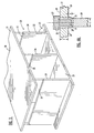
- the structural assembly 20 includes a first structural member 21 which forms the outer skin of one side of the structural assembly.
- the first structural member 21 can be machined, through known manufacturing means, from a single work piece into a predetermined shape and thickness as required by the specific design loads and specifications.
- the first structural member 21 may also be formed, through known manufacturing means, into a curvilinear geometry. No extra material or machining time is required to machine interlocking grooves, as in the current adhesively bonded sandwich construction.
- the structural assembly 20 also includes a second structural member 22 which preferably has a geometry that is evenly mated with the first structural member 21.
- the second structural member 22 includes a skin portion 23 and a plurality of intermediate members 24 which are formed integrally with the skin portion of the second structural member.
- Each of the intermediate members 24 extends outwardly from the skin portion 23 in a predetermined pattern to a corresponding distal end 25.
- the corresponding distal ends 25 are machined to form a pre-selected geometry.
- the skin portion 23, the intermediate members 24 and the corresponding distal ends of the second structural member 22 can be machined, through known manufacturing means, from a single work piece into a predetermined shape and thickness as required by the specific design loads and specifications. For example, a CNC milling machine can be used to machine both the first and second structural members 21, 22.
- the structural assembly 20 is constructed by positioning the first structural member 21 relative to the second structural member 22 such that the plurality of intermediate members 24 extend between the first structural member and the second structural member.
- the inner surface 26 of the first structural member 21 is adjacent to the distal ends 25 of the plurality of intermediate members 24.
- the first and second structural members 21, 22 are then secured so as to prevent motion of the first structural member relative to the second structural member and the plurality of intermediate members 24.
- the first and second structural members 21, 22 may be secured to each other by spot welding.
- structural members 21, 22 may be secured to the. work table by means of a conventional clamp (not shown).
- the bottom surface 26 of the first outer member 21 is then joined to the distal ends 25 of the plurality of intermediate members 24 by friction stir welding.
- a rotating friction stir welding probe 19 which is attached to a friction stir welding tool 27 is forced through the outer surface 28 of the first structural member 21, through the bottom surface 26 and into the distal ends 25 of the plurality of intermediate members 24.
- the frictional heat generated by the rotating tool 27 creates a plasticized region or joint 29 as shown in Figure 4 which solidifies between the first structural member 21 and the distal ends of each of the plurality of intermediate members 24.
- the first structural member and the intermediate members are disposed in a substantially perpendicular relation.
- the rotating probe 19 is then moved along a path through the first structural member 21 that traces the respective intermediate member 24 to thereby form a continuous friction stir weld joint along the length of the intermediate member.
- This friction stir welding process can then be repeated for each of the plurality of intermediate members 24. See U.S. Patent No. 5,460,317 to Thomas et al. for a general discussion of friction stir welding.
- the thickness T of the first structural member and the thickness t of each of the intermediate members will depend upon the properties of the material used to form the first structural member and the second structural member 22, respectively.
- the probe 19 will preferably extend through the first structural member 21 and into the corresponding distal end 25 of each of the plurality of intermediate members 24 a distance d, which will again depend upon the material properties of the base materials as well as the thickness t of the intermediate members 24.
- the corresponding distal ends 25 of intermediate members 24 may be machined to form a variety of geometries.
- the geometry of the distal ends 25 are selected based on the geometry of the first structural member 24 as well as the particular load requirements of the joint between the first structural member and the distal end.
- the distal end 25 is machined to form a rectangular geometry.
- the distal end is machined to form a tapered geometry.
- the distal end is machined to form a "T" shaped geometry.
- the distal end is machined to form an "L" shaped geometry
- the distal end is machined to form a circular tapered geometry.
- the method of the present invention is particularly advantageous to join first and second structural members 21, 22 that are formed of either similar or dissimilar metals which would be unweldable or uneconomical to join by any other means.
- Unweldable materials when joined by conventional welding techniques, produce relatively weak weld joints because these materials possess high conductivity and quickly dissipate heat away from the weld joint.
- Such materials include aluminum and some aluminum alloys, particularly series 2000 and 7000 alloys.
- the method of the present invention permits first and second structural members formed of unweldable materials to be securely joined.
- the method of the present invention may also be used to securely join weldable materials to other weldable and to unweldable materials.
- the method of the present invention permits the materials which form the first and second structural members 21, 22 to be chosen from a wider variety of light weight, high strength metals and alloys, thereby facilitating reduction of the overall weight of the aircraft. Weight and strength are of critical concern in the aerospace industry.
- Friction stir welding creates a severely deformed but highly refined grain structure at the weld interface. Further, friction stir welding results in a more narrow heat-affected zone compared to any fusion welding process and is not limited to selected alloys with properties that are suitable for conventional welding. Friction stir welding eliminates a number of defects related to conventional welding, such as microcracks, poor ductility, lack of fusion, porosity and most importantly, minimization of distortion which can adversely effect the shape and tolerances of the joined component members. In instances where the first and second structural members 21, 22 are formed of the same material, the joint 29 which consists of the plasticized material from the first structural member 21 and the corresponding distal end 25 of the intermediate member 24 will have substantially the same mechanical properties, including strength, as the base materials.
- the joint 29 will have the strength of the weaker material so long as the first structural member and the plurality of intermediate members are each formed from a material, such as aluminum, aluminum alloys, titanium, titanium alloys or the like, which creates a full-strength metallurgical bond when joined through friction welding.
- the resulting joint 29 in structural assembly 20 is of significantly greater strength than that provided by conventional structural assemblies, especially those utilizing adhesives.
- the first step includes machining a work piece to form a first structural member having inner and outer surfaces and may be performed simultaneously with the second step.
- the first structural member may also be formed into a curvilinear geometry. See block 30.
- the second step includes machining a second work piece to form a second structural member having a plurality of intermediate members, each of the plurality of intermediate members extending outwardly in a predetermined pattern to a corresponding distal end. See block 31 .
- first structural member is positioned adjacent to the distal ends of the plurality of intermediate members so that the plurality of intermediate members extend between the first and second structural members. See block 32 .
- the first and second structural members must then be secured to each other by spot welding and then to the work table by clamping, so as to prevent movement of the first structural member relative to the second structural member and the plurality of intermediate members. See block 33 .
- the first structural member is then joined to the corresponding distal ends of each of the plurality of intermediate members by friction stir welding. See block 34 .
- the friction stir welding is preformed by extending rotating friction stir welding probe through the first outer member into the distal end of the intermediate member. Thereafter, the structural assembly is secured to other structural assemblies to form the frame of an aircraft.
Landscapes
- Engineering & Computer Science (AREA)
- Mechanical Engineering (AREA)
- Pressure Welding/Diffusion-Bonding (AREA)
- Joining Of Building Structures In Genera (AREA)
- Rod-Shaped Construction Members (AREA)
Description
Claims (13)
- A method of manufacturing a structural assembly (20), comprising the steps of:machining a first work piece to form a first structural member (21) having outer and inner surfaces;machining a second work piece to form a second structural member (22), the second structural member having a plurality of intermediate members (24) disposed in a predetermined pattern, each of the plurality of intermediate members extending outwardly to a distal end (25);positioning the inner surface (26) of the first structural member adjacent to the distal ends (25) of the plurality of intermediate members (24) so that the plurality of intermediate members extend between the first and second structural members;securing the first and second structural members so as to prevent movement of the first structural member relative to the second structural member; and characterized byinserting a rotating friction stir welding probe (19) through the outer surface of the first structural member at a position aligned with a respective intermediate member to thereby join the first structural member to the distal end of the respective intermediate member by friction stir welding.
- A method according to Claim 1 further comprising repeating said inserting step at positions as figured with each of the intermediate members to thereby joint the first structural member to the distal end of each of the plurality of intermediate members by friction stir welding.
- A method according to Claim 1 wherein said inserting step comprises inserting the rotating friction stir welding probe completely through the first structural member and into the distal end of the respective intermediate member.
- A method according to Claim 1 further comprising the step of moving the rotating friction stir welding probe through the first structural member along a path that traces the distal end of the respective intermediate member to thereby form a continuous joint along the length of the respective intermediate member.
- A method according to Claim 1 further comprising the step of forming the first structural member into a curvilinear geometry.
- The method of Claim 1, further comprising the step of securing the structural assembly to other structural assemblies to form the frame of an aircraft.
- A structural assembly, comprising:a first structural member (21);a second structural member (22) spaced from said first structural member and having a plurality of intermediate members (25) extending outwardly in a predetermined pattern, each of said plurality of intermediate members extending between said first structural member and said second structural member; and characterized in thata friction stir weld joint (29) which joins a respective intermediate member and the first structural member, said joint (29) extending through the outer surface of the first structural member at a position aligned with said respective intermediate member to thereby join the first structural member to the distal end of the respective intermediate member.
- The structural assembly of Claim 7 wherein said first structural member and said second structural member comprise dissimilar metals.
- The structural assembly of Claim 7 wherein said first and second structural members are formed of materials selected from the group consisting of aluminum, 2000 series aluminum alloys, and 7000 series aluminum alloys.
- The structural assembly of Claim 7 further comprising a plurality of friction stir weld joints joining respective ones of said intermediate members and said first structural member.
- The structural assembly of Claim 7 wherein the friction stir weld joint extends along the length of the respective intermediate member.
- The structural assembly of Claim 7 wherein the respective intermediate member is disposed perpendicularly in relation to the first structural member.
- The structural assembly of Claim 7 wherein at least one of the first and second structural members is comprised of an unweldable material.
Applications Claiming Priority (3)
| Application Number | Priority Date | Filing Date | Title |
|---|---|---|---|
| US997430 | 1997-12-23 | ||
| US08/997,430 US6051325A (en) | 1997-12-23 | 1997-12-23 | Joining of machined sandwich assemblies by friction stir welding |
| PCT/US1998/027457 WO1999032255A1 (en) | 1997-12-23 | 1998-12-23 | Joining of machined sandwich assemblies by friction stir welding |
Publications (2)
| Publication Number | Publication Date |
|---|---|
| EP1042099A1 EP1042099A1 (en) | 2000-10-11 |
| EP1042099B1 true EP1042099B1 (en) | 2003-05-07 |
Family
ID=25544015
Family Applications (1)
| Application Number | Title | Priority Date | Filing Date |
|---|---|---|---|
| EP98966749A Expired - Lifetime EP1042099B1 (en) | 1997-12-23 | 1998-12-23 | Joining of machined sandwich assemblies by friction stir welding |
Country Status (5)
| Country | Link |
|---|---|
| US (1) | US6051325A (en) |
| EP (1) | EP1042099B1 (en) |
| DE (1) | DE69814461T2 (en) |
| NO (1) | NO319176B1 (en) |
| WO (1) | WO1999032255A1 (en) |
Families Citing this family (71)
| Publication number | Priority date | Publication date | Assignee | Title |
|---|---|---|---|---|
| GB9713209D0 (en) * | 1997-06-20 | 1997-08-27 | British Aerospace | Friction welding metal components |
| JP3589863B2 (en) * | 1997-07-23 | 2004-11-17 | 株式会社日立製作所 | Structure and friction stir welding method |
| JP3070735B2 (en) * | 1997-07-23 | 2000-07-31 | 株式会社日立製作所 | Friction stir welding method |
| JP3030269B2 (en) * | 1997-08-28 | 2000-04-10 | 昭和アルミニウム株式会社 | Closed container with partition |
| US6247633B1 (en) * | 1999-03-02 | 2001-06-19 | Ford Global Technologies, Inc. | Fabricating low distortion lap weld construction |
| JP3481501B2 (en) * | 1999-05-28 | 2003-12-22 | 株式会社日立製作所 | Structure and method of manufacturing the same |
| TW449519B (en) | 1999-05-31 | 2001-08-11 | Hitachi Ltd | A manufacturing method of a structure body |
| DE19960909A1 (en) * | 1999-09-03 | 2001-06-21 | Eads Airbus Gmbh | Large-area structural component for an aircraft and method for producing the structural component |
| US6986452B2 (en) * | 1999-09-03 | 2006-01-17 | Lockheed Martin Corporation | Friction stir welding as a rivet replacement technology |
| JP3552978B2 (en) * | 2000-01-27 | 2004-08-11 | 株式会社日立製作所 | Hollow profile |
| DE60134777D1 (en) | 2000-05-08 | 2008-08-21 | Univ Brigham Young | TURNING PIPE WELDING BY MEANS OF A SUPER ABRASIVE TOOL |
| DE10036614A1 (en) * | 2000-07-27 | 2002-02-07 | Philips Corp Intellectual Pty | Process for joining workpieces |
| US6352193B1 (en) | 2000-08-01 | 2002-03-05 | General Electric Company | Apparatus for joining electrically conductive materials |
| US6619600B1 (en) * | 2000-08-11 | 2003-09-16 | Weber-Stephen Products Co. | Barbecue gas grill having a welded frame assembly |
| JP3538378B2 (en) * | 2000-10-27 | 2004-06-14 | 株式会社日立製作所 | Friction stir welding method |
| US6998752B2 (en) * | 2000-12-27 | 2006-02-14 | Hitachi, Ltd. | Dynamo-electric machine |
| US6732901B2 (en) * | 2001-06-12 | 2004-05-11 | Brigham Young University Technology Transfer Office | Anvil for friction stir welding high temperature materials |
| JP3751236B2 (en) * | 2001-08-24 | 2006-03-01 | 株式会社日立製作所 | Friction stir welding method |
| WO2003045615A2 (en) * | 2001-11-27 | 2003-06-05 | THE UNITED STATES OF AMERICA as represented by the ADMINISTRATOR OF THE NATIONAL AERONAUTICS AND SPACE | Thermal stir welding process and apparatus |
| JP3510612B2 (en) * | 2001-11-27 | 2004-03-29 | 川崎重工業株式会社 | Friction stir welding method |
| DE20202108U1 (en) * | 2002-02-13 | 2003-06-26 | Horst Witte Entwicklungs- und Vertriebs-KG, 21369 Nahrendorf | Sandwich panel to build up workpiece fixtures |
| US6742697B2 (en) * | 2002-04-29 | 2004-06-01 | The Boeing Company | Joining of structural members by friction plug welding |
| US6908690B2 (en) * | 2002-04-29 | 2005-06-21 | The Boeing Company | Method and apparatus for friction stir welding |
| CA2494143C (en) * | 2002-08-07 | 2011-07-19 | Eclipse Aviation Corporation | Method of friction stir welding surfaces with polymer sealant |
| GB0225518D0 (en) * | 2002-11-01 | 2002-12-11 | Airbus Uk Ltd | Welding method |
| JP2006518671A (en) * | 2003-01-30 | 2006-08-17 | スミス インターナショナル、インコーポレテッド | Out-of-position friction stir welding of high melting point materials |
| WO2004101205A2 (en) * | 2003-05-05 | 2004-11-25 | Smith International, Inc. | Applications of friction stir welding using a superabrasive tool |
| US6933057B2 (en) * | 2003-07-17 | 2005-08-23 | The Boeing Company | Friction stir welded assembly and method of forming a friction stir welded assembly |
| WO2005084162A2 (en) * | 2003-08-04 | 2005-09-15 | Smith International, Inc. | Crack repair using friction stir welding on materials including metal matrix composites, ferrous alloys, non-ferrous alloys, and superalloys |
| US20050116012A1 (en) * | 2003-11-26 | 2005-06-02 | Packer Scott M. | Method for metal and alloy joining using bulk friction stir welding |
| US7225967B2 (en) | 2003-12-16 | 2007-06-05 | The Boeing Company | Structural assemblies and preforms therefor formed by linear friction welding |
| US7398911B2 (en) * | 2003-12-16 | 2008-07-15 | The Boeing Company | Structural assemblies and preforms therefor formed by friction welding |
| US7048175B2 (en) * | 2003-12-19 | 2006-05-23 | The Boeing Company | Friction welded structural assembly and preform and method for same |
| GB0329898D0 (en) * | 2003-12-23 | 2004-01-28 | Airbus Uk Ltd | Welding process for large structures |
| US20050210820A1 (en) * | 2004-03-24 | 2005-09-29 | Shinmaywa Industries, Ltd. | Frame and method for fabricating the same |
| US8186561B2 (en) * | 2004-03-24 | 2012-05-29 | Megastir Technologies, LLC | Solid state processing of hand-held knife blades to improve blade performance |
| MXPA06010846A (en) * | 2004-03-24 | 2007-10-02 | Sii Megadiamond Inc | Solid state processing of materials through friction stir processing and friction stir mixing. |
| US20100078224A1 (en) | 2004-05-21 | 2010-04-01 | Smith International, Inc. | Ball hole welding using the friction stir welding (fsw) process |
| US20060049234A1 (en) * | 2004-05-21 | 2006-03-09 | Flak Richard A | Friction stirring and its application to drill bits, oil field and mining tools, and components in other industrial applications |
| JP2006007258A (en) * | 2004-06-24 | 2006-01-12 | Mitsubishi Heavy Ind Ltd | Friction stir welding method, apparatus therefor, and backing tool |
| US7156276B2 (en) | 2004-07-22 | 2007-01-02 | The Boeing Company | Apparatus and system for welding preforms and associated method |
| US20060071124A1 (en) * | 2004-09-30 | 2006-04-06 | The Boeing Company | Reinforced structural assembly having a lap joint and method for forming the same |
| WO2006044215A2 (en) * | 2004-10-05 | 2006-04-27 | Smith International, Inc. | Expandable mandrel for use in friction stir welding |
| US7210611B2 (en) | 2004-10-21 | 2007-05-01 | The Boeing Company | Formed structural assembly and associated preform and method |
| WO2006066237A2 (en) * | 2004-12-17 | 2006-06-22 | Sii Megadiamond, Inc. | Single body friction stir welding tool for high melting temperature materials |
| US7508682B2 (en) * | 2005-09-19 | 2009-03-24 | Hitachi, Ltd. | Housing for an electronic circuit |
| US20080041921A1 (en) * | 2005-09-26 | 2008-02-21 | Kevin Creehan | Friction stir fabrication |
| US9266191B2 (en) | 2013-12-18 | 2016-02-23 | Aeroprobe Corporation | Fabrication of monolithic stiffening ribs on metallic sheets |
| US8632850B2 (en) | 2005-09-26 | 2014-01-21 | Schultz-Creehan Holdings, Inc. | Friction fabrication tools |
| US8875976B2 (en) | 2005-09-26 | 2014-11-04 | Aeroprobe Corporation | System for continuous feeding of filler material for friction stir welding, processing and fabrication |
| US9511445B2 (en) | 2014-12-17 | 2016-12-06 | Aeroprobe Corporation | Solid state joining using additive friction stir processing |
| US9511446B2 (en) | 2014-12-17 | 2016-12-06 | Aeroprobe Corporation | In-situ interlocking of metals using additive friction stir processing |
| US8397974B2 (en) | 2005-09-26 | 2013-03-19 | Aeroprobe Corporation | Self-reacting friction stir welding tool with the ability to add filler material |
| US8056797B2 (en) * | 2005-10-05 | 2011-11-15 | Megastir Technologies | Expandable mandrel for use in friction stir welding |
| US8550326B2 (en) | 2005-10-05 | 2013-10-08 | Megastir Technologies Llc | Expandable mandrel for use in friction stir welding |
| FR2894859A1 (en) * | 2005-12-16 | 2007-06-22 | Alcan Rhenalu Sa | SOLDER SAIL LONGERON AND METHOD OF MAKING SAME |
| JP2009525181A (en) * | 2006-01-31 | 2009-07-09 | エスアイアイ・メガダイアモンド・インコーポレーテッド | Thermally reinforced tool for friction stir |
| JP4594882B2 (en) | 2006-03-09 | 2010-12-08 | 本田技研工業株式会社 | Friction stir welding apparatus and friction stir welding method |
| JP2007301573A (en) * | 2006-05-08 | 2007-11-22 | Honda Motor Co Ltd | Friction stirring and joining method and friction stirred and joined structure |
| US9015948B2 (en) * | 2008-01-19 | 2015-04-28 | The Boeing Company | Joining fuselage skins using friction stir welding |
| US8100316B2 (en) * | 2008-05-29 | 2012-01-24 | Airbus Operations Gmbh | Method for joining aircraft fuselage elements by friction stir welding (fsw) |
| CN102112263B (en) * | 2008-07-07 | 2014-07-16 | 肯联铝业瑞士有限公司 | Fusion welding process to join aluminium and titanium |
| US20100199590A1 (en) * | 2009-02-06 | 2010-08-12 | Aar Corp. | Aircraft Cargo Pallet and Method of Manufacture |
| CA2779075C (en) * | 2009-11-02 | 2016-05-10 | Megastir Technologies Llc | Out of position friction stir welding of casing and small diameter tubing or pipe |
| DE102010032402A1 (en) * | 2010-07-27 | 2012-02-02 | Airbus Operations Gmbh | Method of joining two aircraft body segments by means of friction stir welding |
| US8317080B2 (en) | 2010-08-02 | 2012-11-27 | Megastir Technologies Llc | Methods to fabricate fully enclosed hollow structures using friction stir welding |
| JP5320439B2 (en) * | 2011-06-14 | 2013-10-23 | 株式会社日立製作所 | High corrosion resistance plant equipment |
| US10583519B2 (en) * | 2016-08-12 | 2020-03-10 | The Boeing Company | Friction stir welding method and assembly |
| JP7089034B2 (en) | 2017-10-31 | 2022-06-21 | メルド マニファクチャリング コーポレーション | Solid-state laminated modeling system as well as material composition and structural background |
| US10478916B2 (en) * | 2017-11-02 | 2019-11-19 | GM Global Technology Operations LLC | Method and apparatus for joining components with friction pins |
| JP7478378B2 (en) | 2020-09-11 | 2024-05-07 | 冨士端子工業株式会社 | Method for joining dissimilar metals |
Family Cites Families (9)
| Publication number | Priority date | Publication date | Assignee | Title |
|---|---|---|---|---|
| GB1385473A (en) * | 1966-09-01 | 1975-02-26 | Luc Penelope Jane Vesey | Bonding |
| US5273806A (en) * | 1991-10-03 | 1993-12-28 | Lockshaw James J | Structural element with interlocking ribbing |
| GB9125978D0 (en) * | 1991-12-06 | 1992-02-05 | Welding Inst | Hot shear butt welding |
| US5736221A (en) * | 1995-07-21 | 1998-04-07 | Hardigg Industries, Inc. | Welded plastic panels and method of making same |
| GB2306366A (en) * | 1995-10-20 | 1997-05-07 | Welding Inst | Friction stir welding |
| US5713706A (en) * | 1995-12-19 | 1998-02-03 | Shur-Lok Corporation | Plastic composite fastener for self-cutting and frictional welding |
| CN1165403C (en) * | 1996-03-19 | 2004-09-08 | 株式会社日立制作所 | Structural body for friction welding |
| US5862975A (en) * | 1996-03-20 | 1999-01-26 | The Boeing Company | Composite/metal structural joint with welded Z-pins |
| US5697511A (en) * | 1996-09-27 | 1997-12-16 | Boeing North American, Inc. | Tank and method of fabrication |
-
1997
- 1997-12-23 US US08/997,430 patent/US6051325A/en not_active Expired - Lifetime
-
1998
- 1998-12-23 DE DE69814461T patent/DE69814461T2/en not_active Expired - Lifetime
- 1998-12-23 EP EP98966749A patent/EP1042099B1/en not_active Expired - Lifetime
- 1998-12-23 WO PCT/US1998/027457 patent/WO1999032255A1/en active IP Right Grant
-
2000
- 2000-04-28 NO NO20002260A patent/NO319176B1/en not_active IP Right Cessation
Also Published As
| Publication number | Publication date |
|---|---|
| DE69814461T2 (en) | 2003-11-20 |
| US6051325A (en) | 2000-04-18 |
| EP1042099A1 (en) | 2000-10-11 |
| NO20002260L (en) | 2000-08-23 |
| WO1999032255A1 (en) | 1999-07-01 |
| NO319176B1 (en) | 2005-06-27 |
| DE69814461D1 (en) | 2003-06-12 |
| NO20002260D0 (en) | 2000-04-28 |
Similar Documents
| Publication | Publication Date | Title |
|---|---|---|
| EP1042099B1 (en) | Joining of machined sandwich assemblies by friction stir welding | |
| CA2337725C (en) | Integral structural shell component for an aircraft and method of manufacturing the same | |
| EP0989920B1 (en) | Friction welding metal components | |
| KR100593372B1 (en) | Method of joining structural members by friction plug welding | |
| EP1745882B1 (en) | Friction stir welding method of joining at least two adjoining work-pieces with application of an adhesive between the at least two workpieces | |
| US7189064B2 (en) | Friction stir welded hollow airfoils and method therefor | |
| EP2344378B2 (en) | System and method for integrally forming a substructure element with a fiber metal laminate | |
| US7225967B2 (en) | Structural assemblies and preforms therefor formed by linear friction welding | |
| US7347351B2 (en) | Apparatus and system for unitized friction stir welded structures and associated method | |
| EP1875981B1 (en) | Structural joint and method of forming | |
| US6976343B2 (en) | Compressive flange sinusoidal structural member | |
| US20060240220A1 (en) | Composite-to-metal joint | |
| US6387469B1 (en) | Composite part and method for producing the same | |
| JPH1147959A (en) | Manufacture of outside sheet | |
| US20060286333A1 (en) | Method of and apparatus for weld-bonding workpieces | |
| US20020029846A1 (en) | Method of manufacture of a structure and a structural member for use in the method | |
| JPH1052773A (en) | Manufacture of structure for railway vehicle and its device | |
| JP3333394B2 (en) | Panel manufacturing method and panel | |
| JP2005239029A (en) | Railway vehicle structural body | |
| EP4159415A1 (en) | Method for joining fibre reinforced composite parts using friction stir welding along a butt joint, aircraft component and aircraft | |
| JP3341831B2 (en) | Friction welding method, its structure and friction welding device | |
| US6082938A (en) | Integral frame and method of manufacture | |
| US5836729A (en) | Integrated frame and method of manufacture | |
| JP4043005B2 (en) | Friction welding method | |
| JP4294168B2 (en) | Bonded joint structure and metal hollow material |
Legal Events
| Date | Code | Title | Description |
|---|---|---|---|
| PUAI | Public reference made under article 153(3) epc to a published international application that has entered the european phase |
Free format text: ORIGINAL CODE: 0009012 |
|
| 17P | Request for examination filed |
Effective date: 20000608 |
|
| AK | Designated contracting states |
Kind code of ref document: A1 Designated state(s): DE FR GB SE |
|
| RIN1 | Information on inventor provided before grant (corrected) |
Inventor name: MARTIN, RICKY, L. Inventor name: MOENSTER, BARTON Inventor name: TALWAR, RAJESH |
|
| GRAH | Despatch of communication of intention to grant a patent |
Free format text: ORIGINAL CODE: EPIDOS IGRA |
|
| GRAH | Despatch of communication of intention to grant a patent |
Free format text: ORIGINAL CODE: EPIDOS IGRA |
|
| GRAA | (expected) grant |
Free format text: ORIGINAL CODE: 0009210 |
|
| AK | Designated contracting states |
Designated state(s): DE FR GB SE |
|
| REG | Reference to a national code |
Ref country code: GB Ref legal event code: FG4D |
|
| REG | Reference to a national code |
Ref country code: SE Ref legal event code: TRGR |
|
| REF | Corresponds to: |
Ref document number: 69814461 Country of ref document: DE Date of ref document: 20030612 Kind code of ref document: P |
|
| PLBE | No opposition filed within time limit |
Free format text: ORIGINAL CODE: 0009261 |
|
| STAA | Information on the status of an ep patent application or granted ep patent |
Free format text: STATUS: NO OPPOSITION FILED WITHIN TIME LIMIT |
|
| ET | Fr: translation filed | ||
| 26N | No opposition filed |
Effective date: 20040210 |
|
| PGFP | Annual fee paid to national office [announced via postgrant information from national office to epo] |
Ref country code: FR Payment date: 20041217 Year of fee payment: 7 |
|
| PG25 | Lapsed in a contracting state [announced via postgrant information from national office to epo] |
Ref country code: FR Free format text: LAPSE BECAUSE OF NON-PAYMENT OF DUE FEES Effective date: 20060831 |
|
| REG | Reference to a national code |
Ref country code: FR Ref legal event code: ST Effective date: 20060831 |
|
| PGFP | Annual fee paid to national office [announced via postgrant information from national office to epo] |
Ref country code: SE Payment date: 20171229 Year of fee payment: 20 Ref country code: GB Payment date: 20171227 Year of fee payment: 20 |
|
| PGFP | Annual fee paid to national office [announced via postgrant information from national office to epo] |
Ref country code: DE Payment date: 20171229 Year of fee payment: 20 |
|
| REG | Reference to a national code |
Ref country code: DE Ref legal event code: R071 Ref document number: 69814461 Country of ref document: DE |
|
| REG | Reference to a national code |
Ref country code: GB Ref legal event code: PE20 Expiry date: 20181222 |
|
| REG | Reference to a national code |
Ref country code: SE Ref legal event code: EUG |
|
| PG25 | Lapsed in a contracting state [announced via postgrant information from national office to epo] |
Ref country code: GB Free format text: LAPSE BECAUSE OF EXPIRATION OF PROTECTION Effective date: 20181222 |