EP1041947B1 - Rehabilitative shoe insole device - Google Patents
Rehabilitative shoe insole device Download PDFInfo
- Publication number
- EP1041947B1 EP1041947B1 EP98962160A EP98962160A EP1041947B1 EP 1041947 B1 EP1041947 B1 EP 1041947B1 EP 98962160 A EP98962160 A EP 98962160A EP 98962160 A EP98962160 A EP 98962160A EP 1041947 B1 EP1041947 B1 EP 1041947B1
- Authority
- EP
- European Patent Office
- Prior art keywords
- catalyst
- foot
- insert
- cavity
- target area
- Prior art date
- Legal status (The legal status is an assumption and is not a legal conclusion. Google has not performed a legal analysis and makes no representation as to the accuracy of the status listed.)
- Expired - Lifetime
Links
- 239000003054 catalyst Substances 0.000 claims abstract description 80
- 210000002683 foot Anatomy 0.000 claims abstract description 58
- 210000000412 mechanoreceptor Anatomy 0.000 claims abstract description 5
- 230000000638 stimulation Effects 0.000 claims abstract description 3
- 239000000463 material Substances 0.000 claims description 17
- 210000000988 bone and bone Anatomy 0.000 claims description 6
- 230000005021 gait Effects 0.000 claims description 5
- 239000006260 foam Substances 0.000 claims description 4
- 210000000705 lateral cuneiform Anatomy 0.000 claims description 4
- 230000004044 response Effects 0.000 claims description 4
- 239000012530 fluid Substances 0.000 claims description 2
- 230000000272 proprioceptive effect Effects 0.000 abstract description 13
- 230000006378 damage Effects 0.000 abstract description 7
- 208000027418 Wounds and injury Diseases 0.000 abstract description 6
- 208000014674 injury Diseases 0.000 abstract description 6
- 230000008713 feedback mechanism Effects 0.000 abstract description 3
- 210000000452 mid-foot Anatomy 0.000 abstract description 3
- 210000003205 muscle Anatomy 0.000 abstract description 3
- 230000000704 physical effect Effects 0.000 abstract 2
- 230000001939 inductive effect Effects 0.000 abstract 1
- 239000000945 filler Substances 0.000 description 32
- 230000007246 mechanism Effects 0.000 description 13
- 230000006835 compression Effects 0.000 description 12
- 238000007906 compression Methods 0.000 description 12
- 238000013461 design Methods 0.000 description 11
- 210000000474 heel Anatomy 0.000 description 11
- 230000000694 effects Effects 0.000 description 7
- 238000012423 maintenance Methods 0.000 description 7
- 229920000642 polymer Polymers 0.000 description 6
- 230000037396 body weight Effects 0.000 description 5
- 238000003780 insertion Methods 0.000 description 5
- 230000037431 insertion Effects 0.000 description 5
- 230000008901 benefit Effects 0.000 description 4
- 239000000853 adhesive Substances 0.000 description 3
- 230000001070 adhesive effect Effects 0.000 description 3
- 210000000459 calcaneus Anatomy 0.000 description 3
- 210000001872 metatarsal bone Anatomy 0.000 description 3
- 238000000034 method Methods 0.000 description 3
- 230000007170 pathology Effects 0.000 description 3
- 210000003484 anatomy Anatomy 0.000 description 2
- 230000004064 dysfunction Effects 0.000 description 2
- 210000004744 fore-foot Anatomy 0.000 description 2
- 238000010348 incorporation Methods 0.000 description 2
- 230000003993 interaction Effects 0.000 description 2
- 238000004519 manufacturing process Methods 0.000 description 2
- 230000004936 stimulating effect Effects 0.000 description 2
- OKTJSMMVPCPJKN-UHFFFAOYSA-N Carbon Chemical compound [C] OKTJSMMVPCPJKN-UHFFFAOYSA-N 0.000 description 1
- 229920004943 Delrin® Polymers 0.000 description 1
- 206010033372 Pain and discomfort Diseases 0.000 description 1
- 229920002614 Polyether block amide Polymers 0.000 description 1
- 239000004957 Zytel Substances 0.000 description 1
- 229920006102 Zytel® Polymers 0.000 description 1
- 230000009471 action Effects 0.000 description 1
- 230000009286 beneficial effect Effects 0.000 description 1
- 230000008602 contraction Effects 0.000 description 1
- 230000006353 environmental stress Effects 0.000 description 1
- 239000004744 fabric Substances 0.000 description 1
- 239000011152 fibreglass Substances 0.000 description 1
- 229910002804 graphite Inorganic materials 0.000 description 1
- 239000010439 graphite Substances 0.000 description 1
- 238000001746 injection moulding Methods 0.000 description 1
- 230000010354 integration Effects 0.000 description 1
- 230000002452 interceptive effect Effects 0.000 description 1
- 210000003041 ligament Anatomy 0.000 description 1
- 230000037081 physical activity Effects 0.000 description 1
- 238000005086 pumping Methods 0.000 description 1
- 238000009877 rendering Methods 0.000 description 1
- 239000011347 resin Substances 0.000 description 1
- 229920005989 resin Polymers 0.000 description 1
- 230000000284 resting effect Effects 0.000 description 1
- 238000010008 shearing Methods 0.000 description 1
- 210000002435 tendon Anatomy 0.000 description 1
- 210000001519 tissue Anatomy 0.000 description 1
- 238000007666 vacuum forming Methods 0.000 description 1
Images





Classifications
-
- A—HUMAN NECESSITIES
- A43—FOOTWEAR
- A43B—CHARACTERISTIC FEATURES OF FOOTWEAR; PARTS OF FOOTWEAR
- A43B7/00—Footwear with health or hygienic arrangements
- A43B7/14—Footwear with health or hygienic arrangements with foot-supporting parts
- A43B7/1405—Footwear with health or hygienic arrangements with foot-supporting parts with pads or holes on one or more locations, or having an anatomical or curved form
- A43B7/1415—Footwear with health or hygienic arrangements with foot-supporting parts with pads or holes on one or more locations, or having an anatomical or curved form characterised by the location under the foot
- A43B7/142—Footwear with health or hygienic arrangements with foot-supporting parts with pads or holes on one or more locations, or having an anatomical or curved form characterised by the location under the foot situated under the medial arch, i.e. under the navicular or cuneiform bones
-
- A—HUMAN NECESSITIES
- A43—FOOTWEAR
- A43B—CHARACTERISTIC FEATURES OF FOOTWEAR; PARTS OF FOOTWEAR
- A43B7/00—Footwear with health or hygienic arrangements
- A43B7/14—Footwear with health or hygienic arrangements with foot-supporting parts
- A43B7/22—Footwear with health or hygienic arrangements with foot-supporting parts with fixed flat-foot insertions, metatarsal supports, ankle flaps or the like
-
- A—HUMAN NECESSITIES
- A61—MEDICAL OR VETERINARY SCIENCE; HYGIENE
- A61F—FILTERS IMPLANTABLE INTO BLOOD VESSELS; PROSTHESES; DEVICES PROVIDING PATENCY TO, OR PREVENTING COLLAPSING OF, TUBULAR STRUCTURES OF THE BODY, e.g. STENTS; ORTHOPAEDIC, NURSING OR CONTRACEPTIVE DEVICES; FOMENTATION; TREATMENT OR PROTECTION OF EYES OR EARS; BANDAGES, DRESSINGS OR ABSORBENT PADS; FIRST-AID KITS
- A61F5/00—Orthopaedic methods or devices for non-surgical treatment of bones or joints; Nursing devices ; Anti-rape devices
- A61F5/01—Orthopaedic devices, e.g. long-term immobilising or pressure directing devices for treating broken or deformed bones such as splints, casts or braces
- A61F5/14—Special medical insertions for shoes for flat-feet, club-feet or the like
Definitions
- the present invention relates to an insole for a shoe.
- the present invention relates to an insole device that can rehabilitate a foot by stimulating a proprioceptive response in the wearer's foot.
- Patent 5,404,659 the device has an ideal apex height of 5.28% to 7.6% of the total foot length.
- a device built according to these dimensions results in a overly high arch height, and can cause severe discomfort, and possible injury, to a wearer. It is further disclosed that the absolute, non-weight bearing height of the device should be the same regardless of body weight and arch height. This is clearly wrong, since different wearers will have different comfort thresholds and arch heights.
- the device disclosed in U.S. Patent 5,404,659 does not function as described. Wearers would find the device too hard to use successfully, and rather than stimulating a proprioceptive response, the device would cause pain and discomfort at each step. The pain engendered in the foot of a wearer would, in fact, cause the wearer to limit the pressure applied to the foot to avoid the discomfort, rather than exercising the foot by creating an imperceptible stimulation as is its stated goal.
- the present invention provides a shoe insole or midsole units that utilize proprioceptive feedback mechanisms in the human body to increase the structural integrity of the human foot.
- the improvements will introduce provisions allowing the arch rehabilitative catalyst to be consistently located at the desired anatomical location as well as to ease the interaction of the arch rehabilitative catalyst and the wearer. Improvements will also be presented to provide an increased longevity of the arch rehabilitative catalyst, as well to provide a gradual multi-directional interfacing with the arch rehabilitative catalyst.
- an improved arch rehabilitative catalyst In one aspect of the invention there is provided an improved arch rehabilitative catalyst. In another aspect of the invention there is provided an improved ease of inter-changing of the arch rehabilitative catalyst. In another aspect of the invention there is provided designs and systems which improve the longevity of the rebound, deflection and compression characteristics of the arch rehabilitative catalyst by introducing a mechanical device. In another aspect of the invention there is provided an improved mechanism allowing gradual multi-directional introduction of the arch rehabilitative catalyst to the plantar aspect of the foot.
- a tapered heel skive allowing for medial to lateral, as well, as anterior to posterior gradual body weight acceptance onto the arch rehabilitative catalyst is presented to increase the comfort of the invention.
- an insole or midsole device 1 is shown.
- Device 1 has a dorsal surface contacting the underside of a foot.
- a proprioceptive catalyst 4 is located in the midsection of device 1, substantially aligned with the apex of the foot's arch system.
- the apex of the arch system is shown at the target area "A" shown in Figures 1 and 2, and is defined as the intersection of the navicular 5, lateral cuneiform 6, and the cuboid 7 bones, or slightly medial thereof.
- a wearer's foot comprises the bones of the foot, interconnected by ligaments.
- a layer of muscle is attached to the bones by tendons, and covered by a thick layer of fat tissue which is finally covered by a layer of skin.
- the proprioceptive catalyst 4 has an area and perimeter 9 defined by an anterior arc, a posterior arc, a medial arc, and a lateral arc.
- the anterior arc has its maximum point lateral to the 2nd metatarsal and medial to the 3rd metatarsal, and does not extend in an anterior direction more than 70% of the total foot length, nor less than 60%;
- the posterior arc has its maximum point medial to the lateral tubercle of the calcaneus and lateral to the medial tubercle, and does not extent in a posterior direction at any point less than 15% of the foot's total length or greater than 25% of the foot's total length; the medial and lateral arcs do not exceed the medial and lateral boundaries created by the foot itself; and the proprioceptive catalyst 4 is entirely within the periphery set by the metatarsal heads, calcaneus, and lateral and medial borders of the foot.
- Proprioceptive catalyst 4 is an asymmetric dome with its apex aligned with target area "A", as described above, when viewed from where from a sagittal plane.
- the height the catalyst 4 at the apex should ensure that, when a user is at rest, target area "A" is at a height between 5.28% and 7.6% of the foot's total length.
- the present inventor has found that this corresponds to an actual catalyst height of in the range of 1% to 5% of the foot's length, with an ideal ration of approximately 3.6% of a wearer's foot length.
- catalyst 4 should be manufactured in such a fashion, and of such a material, that it displays certain preferred compression and rebound characteristics. For example, when the catalyst is subjected to the vertical forces of a person standing at rest, the catalyst will display a deflection between 40% and 100% of its maximum height.
- FIG. 3 A first embodiment of the present invention is shown in Figures 3 through 7.
- the device 1 interfacing with an undercarriage 11 from a sagittal plane view through section A-A'.
- Undercarriage 11 a heel region 3 and midfoot region 10.
- the midfoot region 10 being clearly defined by the presence of a catalyst 4 engineered to function as a domed cantilever spring device 12.
- Cantilever legs 13 flex and compress voids 14, thereby allowing compression of the legs 13 without the fingers 13 interfering with each other during compression.
- the apex 8 of the catalyst, in the form of the mechanical cantilever spring device 12 provides a positioning aperture 17 aligned with a positioning pin 18 in the device 1.
- Positioning apertures 15 are also aligned with positioning pins 16 of the device 1 to ensure the proper placement and maintenance of placement of the catalyst 4 and its apex 8.
- Vertical side walls 23 of the positioning pins 16 and the positioning apertures 15 act to prevent anterior/posterior and medial/lateral shifting of the inserted mechanism as provided in Figures 3, 4, 5 and 6.
- the apertures 15 and corresponding placement pins 16 can be located at any location on the device 1 and the undercarriage 11 as seen fit by design and functionality. Differences in body weight, activity and foot type can be compensated for by the selection of materials for the fabrication of the undercarriage 11 and the cantilever spring device 12, or the thickness of the undercarriage 11 and the cantilever spring device 12.
- the undercarriage 11 and the cantilever spring device 12 can be formed through injection moulding or vacuum forming and stamping.
- Polymers such as Delrin, Hytrel and Zytel from E.I. DuPont, PVC, Pebax or layered fabric and resin combinations such as fibreglass or graphite can provide the desired physical and material properties.
- An advantage of device 1 is the high flex fatigue characteristics of the materials of choice. This will enable the device 1, and in particular the catalyst 4, to be used for much longer periods of time than that disclosed in other shoe insole or midsole units that utilize proprioceptive feedback mechanisms in the human body to increase the structural integrity of the human foot.
- the desired regulation of the vertical maximum distance from the supporting surface of the device 1 to the apex 8 of the catalyst 4 occurs as forces are applied vertically to the cantilever mechanism at its apex 8.
- Figure 5 illustrates an alternative design to the mechanical cantilever spring device 12 where the legs 13 of the cantilever spring device 12 deflect and move away from the centre region.
- the rear finger 20 on the mechanical spring device 12 in Figure 5 can be molded as an integral part of the undercarriage 11 or permanently affixed to an undercarriage 11.
- Each leg 13 of the cantilever spring device 12 has a foot 19 that permits it to smoothly elongate without becoming obstructed by friction between the lower surface of the foot 19 and the layer of the inside of the shoe with which it is in contact.
- This embodiment as illustrated in Figure 5, also incorporates positioning pins 18 and 16, and positioning apertures 15 and 17 and their inherit vertical sidewalls 23 to ensure the proper placement of the catalyst 4 and its apex 8 which maintains the catalyst in its position.
- Figure 6 shows a further configuration for the catalyst 4 of the present invention. It involves the incorporation of a coiled spring device 21 to be aligned to the target area of the apex 8 of the foot's arch system as defined and to be affixed to or designed as an integral part of the undercarriage 11. This is illustrated in Figure 6 where a perspective view of the coiled spring device 21 is shown. Again the incorporation of positioning pins 16 and the positioning apertures 15 and the vertical sidewalls 23 created therein prevent any medial/lateral and anterior/posterior shifting of the mechanism and ensure its proper placement.
- the specific characteristics that are desired for the cantilever spring mechanisms of the present invention can be attained in at least two different ways.
- the first of these is to use the design, particularly the design characteristics of the legs 13 as a constant, and adopt different grades of the aforementioned polymers, or similar.
- the second method of attaining the desired rebound and compression characteristics would be to hold the polymer of choice as a constant and alter the thickness of the legs 13 as shown in Figures 3, 4 and 5.
- the use of the flex modulus information, relative to material thickness, will be able to provide the necessary information as to determine the ideal material thickness.
- the benefit of this, is its ability to provide a variable deflection rate. That is the cantilever mechanism 12 can be designed to react equally efficiently when subjected to varying forces through varying thickness of the legs 13.
- An example of which is the integration of thicker legs 13 if the application is such that it provides an activity or an environmental stress characteristic of greater vertical loading, such as the activity of basketball compared to walking, or a 150 kg athlete compared to a 80 kg athlete, both having the same shoe size.
- the benefits of the improved rehabilitative catalyst of the present invention are generally threefold.
- Third, the catalyst can be designed to obtain the desired compression and spring characteristics required for a particular application. The maintenance of these properties is beneficial because:
- the geometric nature of the plantar aspect of the device 1 in the region of the catalyst 4 it is desirable to redesign the geometric nature of the plantar aspect of the device 1 in the region of the catalyst 4 to facilitate the easy removal and insertion of an appropriately shaped filler object or insert 26, as per a few of the options presented in Figures 10, 13, 16 and 17, or filler mechanism to provide the necessary rebound, compression and deflection traits necessitated by the wearer and to provide vertical walls 25 and 31 thereby ensuring proper positioning of the filler object or insert 26 or mechanism and catalyst and to ensure the proper maintenance of the desired position.
- the inserted filler object or insert 26 allows for customization of the catalyst in the same manner as discussed with reference to the legs 13 of the mechanical device.
- the filler object or insert 26 can be provided in a variety of foam type materials of a variety of heights, harnesses and compression sets to address body weight requirements, foot type characteristics, or activity of usage.
- Previous inventions have featured an catalyst receptacle which has a cavity of truly curvilinear nature and as such there were no vertical walls to ensure proper positioning of the filler object or insert 26 or mechanism and to ensure the proper maintenance of the desired position.
- Figures 8 through 19 reveal options that are available with respect to the redesign of a system that ensures the proper placement of the filler object or insert 26, the maintenance of that placement and the easy removal and insertion of the filler object or insert 26.
- Figures 8 through 10 reveal an device 1, with a forefoot region 2, a heel region 3 and with an catalyst 4 with a distinct apex 8, the target area aligned with the anatomical region encompassing the intersection of the navicular 5, lateral cuneiform 6, and the cuboid 7 bones.
- the plantar surface of the device 1 in the region set forth by the boundaries of the catalyst 4 is characterized by a geometric cavity 24.
- the cavity displays vertical walls 25 for resisting medial-lateral shifting of the filler object or insert 26 and vertical walls 31 for resisting anterior-posterior shifting of the filler object or insert 26.
- the preferred embodiment as detailed in Figures 8 through 10 reveal a geometric cavity 24 of a rectangular nature and a filler object or insert 26 of a corresponding rectangular nature with vertical side walls 27 designed to engage with the vertical sidewalls 25 and 31 of the cavity 24.
- Figures 11 through 13 show a device 1, with a forefoot region 2, a heel region 3 and with a catalyst 4 with an apex 8, the apex aligned with a target area in the foot defined by the anatomical region encompassing the intersection of the navicular 5, lateral cuneiform 6, and the cuboid 7 bones.
- the plantar surface of the device 1 in the region set forth by the boundaries of the catalyst 4 is characterized by a geometric cavity 24.
- the cavity displays vertical walls 25 for engaging with the vertical sidewalls 27 of the filler object or insert 26 for resisting medial-lateral shifting of the filler object or insert 26 and vertical walls 31 for engaging with the vertical sidewalls 27 of the filler object or insert 26 for resisting anterior-posterior shifting of the filler object or insert 26.
- the preferred embodiment as detailed in Figures 11 through 13 reveal a geometric cavity 24 of a pyramidal stacked rectangular nature and a filler object or insert 26 of a corresponding pyramidal stacked rectangular nature.
- the rectangular layers 30 each as an insatiable filler object or insert layer and therefore each of a different material and/or differing material properties.
- variable rate deflection concept outlined earlier can be attained while maintaining and ensuring the proper positioning of the catalyst 4, apex 8 and the filler object or insert 26.
- This variable deflection benefit can also be achieved through the method as provided in Figures 8 through 10 by allowing the filler object or insert 26 to be constructed through the application of stacked layers where each layer is capable of displaying individual deflection, compression and rebound characteristics.
- Figures 14 through 16 display a geometric configuration consistent with Figures 8 through 10 with the exception of the anterior and posterior most ends of the filler object or insert 26, and the anterior and posterior walls of the geometric cavity 24, are curvilinear in nature.
- the geometric cavity 24 can also be designed to facilitate the insertion of an appropriately matching shaped mechanical device providing the desired rebound, deflection and rebound characteristics.
- the mechanical device can take the form of a compressive mechanical system such as coil spring devices, bi-valve spring devices, cantilever spring devices, or fluid filled structures, including gas filled structures.
- the mechanical device is designed to fill the geometric cavity 24 such that the vertical sidewalls 25 and 31 of the geometric cavity 24 engage the mechanical device and ensure the proper and permanent placement of the mechanical device.
- the compressive nature of the mechanical device can be linear in nature or can provide a variable rate of deflection.
- Figures 17 through 19 illustrate a mechanism allowing an filler object or insert 26 of similar shape and design as the curvilinear geometric cavity 24 to be inserted into the curvilinear geometric cavity 24 without risk of the filler object or insert 26 deviating from its desired position.
- apertures 29 are present in the catalyst 4 area of the device 1 which are aligned to positioning and security ribs 28 designed as an integral characteristic of the filler object or insert 26.
- the positioning and security ribs 28 have vertical sidewalls 27 which engage with the vertical sidewalls 25 and 31 of the insole or midsole to prevent any medial-lateral shifting or posterior-anterior shifting of the position of the filler object or insert 26.
- Figure 23 reveals a preferred method of ensuring the presence of vertical sidewalls 31 and 25 in the geometric cavity 24 necessary to secure the filler object or insert 26 and providing an intrinsic cantilever effect.
- Vertical sidewalls 31 and 25 extent vertically downwardly from a maximum height, a predetermined distance, such that the distance is less than the maximum vertical distance from the inside maximum height of the geometric cavity 24 and the plantar supporting surface of the insole 1.
- the lower portion of the geometric cavity 24 is characterized by sidewalls 36 that are tapered. This design further utilizes the material properties of the insole body to provide a further cantilever effect as well as allowing a pumping action upon compression capable of circulating air throughout the in-shoe environment.
- device 1 as described has a heel region 3 comprised of a tapered skive 32, as shown in Figure 20, wherein the maximum skive thickness corresponds with the sagittal plane midline of the calcaneus and tapers by means of a sagittal angle to a level equal to the minimum thickness of the device 1 at the posterior most part of the device 1.
- the tapered step 32 serves to reduce the velocity of the foot once it is planted on the ground at heel strike in normal heel to toe ambulation. This functions as a precaution by allowing the foot to be slowly lowered unto the catalyst 4. In doing so, any risk of impact related injury to the foots arch system is reduced, as well as increasing the initial comfort of the device 1 by allowing the pressure application to be more gradual.
- the tapered skive provided for in other inventions are sufficiently able to perform effectively during uni-directional ambulation but was designed such that it was not very effective in reducing the impact velocity when the foot was planted medially or laterally as in multi-directional sports.
- the purpose of slowly lowering the foot onto the catalyst 4 is still maintained during uni-directional ambulation through the sagittal plane taper created by the slope existing from the anterior most edge 33 and the posterior most edge of the device 1, and this effect can now also be provided for when the insole or midsole device 1 is used in multi-directional sports by the design addition of the medial skive 34 and the lateral skive 35. Again this serves to function as a precaution by allowing the foot to be slowly lowered unto the catalyst 4.
- any risk of impact related injury to the foots arch system is reduced, as well as increasing the initial comfort of the insole or midsole or midsole 1 by allowing the pressure application to be more gradual.
- a non-symmetric altering of the medial and lateral skive 34 and 35 such that their angulations are different can be desirable for the design and creation of sport specific insole or midsoles.
Landscapes
- Health & Medical Sciences (AREA)
- General Health & Medical Sciences (AREA)
- Public Health (AREA)
- Epidemiology (AREA)
- Engineering & Computer Science (AREA)
- Orthopedic Medicine & Surgery (AREA)
- Nursing (AREA)
- Biomedical Technology (AREA)
- Heart & Thoracic Surgery (AREA)
- Vascular Medicine (AREA)
- Life Sciences & Earth Sciences (AREA)
- Animal Behavior & Ethology (AREA)
- Veterinary Medicine (AREA)
- Footwear And Its Accessory, Manufacturing Method And Apparatuses (AREA)
- Orthopedics, Nursing, And Contraception (AREA)
Abstract
Description
- The present invention relates to an insole for a shoe. In particular, the present invention relates to an insole device that can rehabilitate a foot by stimulating a proprioceptive response in the wearer's foot.
- Professionals dealing with gait related pathologies generally accept that a large majority of persons will, at some time in their lives, suffer some form of gait related pain or dysfunction. It is also well accepted that, in the majority of cases, the mechanism underlying the pathology, injury, or dysfunction is biomechanically related to the interface between the foot and the ground, during the support phase of the gait cycle.
- It has been proposed that providing a device to create a proprioceptive, or internal, feedback stimulus to a wearer's foot can directly target the underlying pathology, injury or dysfuntion. Such a device is disclosed in US Patent No. 5,404,659 to Burke et al. As disclosed in US Patent No. 5,404,659, an arch rehabilitative catalyst stimulates the Golgi tendon organ, which in turn, stimulates the musculoskeletal structure of the foot to rehabilitate the foot structure. The catalyst is an asymmetrically domed hump, which creates mild to strong discomfort to initially stimulate the Golgi tendon organ.
- However, it has been found that the device disclosed in U.S. Patent 5,404,659 does not function as described, and that the majority of wearers find the device too uncomfortable to use. In particular, when subjected to conventional vertical compressive forces of a person walking in the range of 2.5 times body weight, the device is designed to deflect between 40% and 60% of its maximum height, and when subject to only one times a person's weight, there should be no deflection. Rather than stimulate the Golgi tendon organ to create a proprioceptive response, deflections in this range can cause severe pain to a wearer, as there is insufficient give, and the wearer is always aware of the presence of the device. In addition, as disclosed in U.S. Patent 5,404,659, the device has an ideal apex height of 5.28% to 7.6% of the total foot length. A device built according to these dimensions results in a overly high arch height, and can cause severe discomfort, and possible injury, to a wearer. It is further disclosed that the absolute, non-weight bearing height of the device should be the same regardless of body weight and arch height. This is clearly wrong, since different wearers will have different comfort thresholds and arch heights.
- In general, the device disclosed in U.S. Patent 5,404,659 does not function as described. Wearers would find the device too hard to use successfully, and rather than stimulating a proprioceptive response, the device would cause pain and discomfort at each step. The pain engendered in the foot of a wearer would, in fact, cause the wearer to limit the pressure applied to the foot to avoid the discomfort, rather than exercising the foot by creating an imperceptible stimulation as is its stated goal.
- The present invention provides a shoe insole or midsole units that utilize proprioceptive feedback mechanisms in the human body to increase the structural integrity of the human foot. The improvements will introduce provisions allowing the arch rehabilitative catalyst to be consistently located at the desired anatomical location as well as to ease the interaction of the arch rehabilitative catalyst and the wearer. Improvements will also be presented to provide an increased longevity of the arch rehabilitative catalyst, as well to provide a gradual multi-directional interfacing with the arch rehabilitative catalyst.
- In one aspect of the invention there is provided an improved arch rehabilitative catalyst. In another aspect of the invention there is provided an improved ease of inter-changing of the arch rehabilitative catalyst. In another aspect of the invention there is provided designs and systems which improve the longevity of the rebound, deflection and compression characteristics of the arch rehabilitative catalyst by introducing a mechanical device. In another aspect of the invention there is provided an improved mechanism allowing gradual multi-directional introduction of the arch rehabilitative catalyst to the plantar aspect of the foot.
- In another aspect of the invention there is provided a number of designs for manufacturing the proper location of the arch rehabilitative catalyst through the introduction of geometric cavities and matching insertable devices with the presence of vertical sidewall interaction. Provisions to the design of these geometric cavities and matching insertable devices will be shown as a system to allow for ease of inter-changing of the arch rehabilitative catalyst support. The ability for the insertable device to be foam in nature or mechanical in nature will allow provisions for linear and/or variable deflection rates of the inserted device as well as allow provisions for the increased durability of the invention.
- In another aspect of the invention there is provided a tapered heel skive allowing for medial to lateral, as well, as anterior to posterior gradual body weight acceptance onto the arch rehabilitative catalyst is presented to increase the comfort of the invention.
- Preferred embodiments of the present invention will now be described, by way of example only, by reference to the attached drawings, in which:
- Figure 1 is a medial sagittal view of an insole showing the location of an arch rehabilitative catalyst relative to foot placement on the insole or midsole;
- Figure 2 is a dorsal view of an insole showing the location of an arch rehabilitative catalyst relative to foot placement;
- Figure 3 is perspective view of a cantilever mechanical spring device of the present invention showing an undercarriage and positioning apertures;
- Figure 4 is a sagittal plane cross-sectional view of the insole or midsole and the cantilever mechanical spring device of Figure 3, through section A-A' of Figure 2;
- Figure 5 is a perspective view of an alternative embodiment of the cantilever mechanical spring device of the present invention to be designed into the undercarriage;
- Figure 6 is a perspective view of another embodiment of a domed shaped coil mechanical spring device of the present invention showing an undercarriage and positioning apertures;
- Figure 7 is a frontal plane cross-sectional view of further embodiment of a domed shaped coil mechanical spring device of the present invention through section B-B' of Figure 2;
- Figures 8a and 8b are frontal and sagittal plane cross sectional views of the insole or midsole through sections A-A' and B-B' of Figure 2 showing the positioning of a rectangular receptacle cavity in the area of the arch rehabilitative catalyst, respectively;
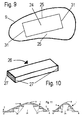
- Figure 9 is a plantar aspect view of the arch rehabilitative catalyst and the rectangular receptacle cavity in the arch rehabilitative catalyst shown in Figures 8a and 8b;
- Figure 10 is a perspective view of an insert that can be inserted into the rectangular receptacle cavity in the arch rehabilitative catalyst;
- Figures11a and 11b are frontal and sagittal plane views of further embodiment of the insole or midsole through sections A-A' and B-B' of Figure 2 showing the positioning of a rectangular pyramidal receptacle cavity in the arch rehabilitative catalyst;
- Figure 12 a plantar aspect view of the arch rehabilitative catalyst and the rectangular pyramidal receptacle cavity in the arch rehabilitative catalyst shown in Figures 11a and 11b;
- Figure 13 a perspective view of an insert that can be inserted into the rectangular pyramidal receptacle cavity in the arch rehabilitative catalyst;
- Figures 14a and 14b are frontal and sagittal plane views of another embodiment of an insole through sections A-A' and B-B' showing the positioning of a rectangular receptacle cavity with curvilinear in the arch rehabilitative catalyst;
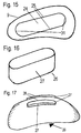
- Figure 15 a plantar aspect view of the arch rehabilitative catalyst and the rectangular receptacle cavity with curvilinear ends in the arch rehabilitative catalyst shown in Figures 14a and 14b;
- Figure 16 is a perspective view of an insert that can be inserted into the rectangular receptacle cavity with curvilinear ends in the arch rehabilitative catalyst shown in Figures 14a and 14b;
- Figure 17 a perspective view of further embodiment of a domed shaped insert with positioning and security ribs on its dorsal aspect;
- Figure 18 is a frontal cross-sectional view of the arch rehabilitative catalyst and insole or midsole through section B-B' of Figure 2 showing the domed shaped insert with 2 positioning and security ribs of Figure 17;
- Figure 19 a frontal cross-sectional view of another embodiment of a arch rehabilitative catalyst and insole or midsole through section B-B' of Figure 2 showing the domed shaped insert with a singular positioning and security rib;
- Figure 20 a medial sagittal view of another embodiment the invention showing the location of the arch rehabilitative catalyst relative to foot placement on the insole or midsole and the posterior heel skive;
- Figure 21 view of the heel region of the insole or midsole device illustrating the location and characteristics of the tapered heel skive as shown in Figure 20;
- Figure 22 a frontal plane cross sectional view through section C-C' of Figure 21 showing the geometric characteristics of the posterior heel skive;
- Figures 23a and 23b are frontal and sagittal plane views of further embodiment of the insole or midsole of the invention through sections A-A' and B-B' of Figure 2 showing the positioning of a rectangular receptacle cavity in the arch rehabilitative catalyst with the cavity displaying a combination of vertical sidewalls and tapered sidewalls.
-
- Referring to Figures 1 and 2, an insole or
midsole device 1 is shown.Device 1 has a dorsal surface contacting the underside of a foot. Aproprioceptive catalyst 4 is located in the midsection ofdevice 1, substantially aligned with the apex of the foot's arch system. The apex of the arch system is shown at the target area "A" shown in Figures 1 and 2, and is defined as the intersection of the navicular 5,lateral cuneiform 6, and the cuboid 7 bones, or slightly medial thereof. As will be understood by those of skill in the art, a wearer's foot comprises the bones of the foot, interconnected by ligaments. A layer of muscle is attached to the bones by tendons, and covered by a thick layer of fat tissue which is finally covered by a layer of skin. - The
proprioceptive catalyst 4 has an area andperimeter 9 defined by an anterior arc, a posterior arc, a medial arc, and a lateral arc. Preferably, the anterior arc has its maximum point lateral to the 2nd metatarsal and medial to the 3rd metatarsal, and does not extend in an anterior direction more than 70% of the total foot length, nor less than 60%; the posterior arc has its maximum point medial to the lateral tubercle of the calcaneus and lateral to the medial tubercle, and does not extent in a posterior direction at any point less than 15% of the foot's total length or greater than 25% of the foot's total length; the medial and lateral arcs do not exceed the medial and lateral boundaries created by the foot itself; and theproprioceptive catalyst 4 is entirely within the periphery set by the metatarsal heads, calcaneus, and lateral and medial borders of the foot. -
Proprioceptive catalyst 4 is an asymmetric dome with its apex aligned with target area "A", as described above, when viewed from where from a sagittal plane. The height thecatalyst 4 at the apex should ensure that, when a user is at rest, target area "A" is at a height between 5.28% and 7.6% of the foot's total length. The present inventor has found that this corresponds to an actual catalyst height of in the range of 1% to 5% of the foot's length, with an ideal ration of approximately 3.6% of a wearer's foot length. - Preferably,
catalyst 4 should be manufactured in such a fashion, and of such a material, that it displays certain preferred compression and rebound characteristics. For example, when the catalyst is subjected to the vertical forces of a person standing at rest, the catalyst will display a deflection between 40% and 100% of its maximum height. - A first embodiment of the present invention is shown in Figures 3 through 7. Referring to Figure 3 and 4, the
device 1 interfacing with anundercarriage 11 from a sagittal plane view through section A-A'. Undercarriage 11 aheel region 3 andmidfoot region 10. Themidfoot region 10 being clearly defined by the presence of acatalyst 4 engineered to function as a domedcantilever spring device 12.Cantilever legs 13 flex and compressvoids 14, thereby allowing compression of thelegs 13 without thefingers 13 interfering with each other during compression. Theapex 8 of the catalyst, in the form of the mechanicalcantilever spring device 12 provides apositioning aperture 17 aligned with apositioning pin 18 in thedevice 1.Positioning apertures 15 are also aligned withpositioning pins 16 of thedevice 1 to ensure the proper placement and maintenance of placement of thecatalyst 4 and itsapex 8.Vertical side walls 23 of the positioning pins 16 and thepositioning apertures 15 act to prevent anterior/posterior and medial/lateral shifting of the inserted mechanism as provided in Figures 3, 4, 5 and 6. Theapertures 15 and corresponding placement pins 16 can be located at any location on thedevice 1 and theundercarriage 11 as seen fit by design and functionality. Differences in body weight, activity and foot type can be compensated for by the selection of materials for the fabrication of theundercarriage 11 and thecantilever spring device 12, or the thickness of theundercarriage 11 and thecantilever spring device 12. Theundercarriage 11 and thecantilever spring device 12 can be formed through injection moulding or vacuum forming and stamping. Polymers such as Delrin, Hytrel and Zytel from E.I. DuPont, PVC, Pebax or layered fabric and resin combinations such as fibreglass or graphite can provide the desired physical and material properties. - An advantage of
device 1 is the high flex fatigue characteristics of the materials of choice. This will enable thedevice 1, and in particular thecatalyst 4, to be used for much longer periods of time than that disclosed in other shoe insole or midsole units that utilize proprioceptive feedback mechanisms in the human body to increase the structural integrity of the human foot. The desired regulation of the vertical maximum distance from the supporting surface of thedevice 1 to theapex 8 of thecatalyst 4 occurs as forces are applied vertically to the cantilever mechanism at itsapex 8. - Figure 5 illustrates an alternative design to the mechanical
cantilever spring device 12 where thelegs 13 of thecantilever spring device 12 deflect and move away from the centre region. Therear finger 20 on themechanical spring device 12 in Figure 5 can be molded as an integral part of theundercarriage 11 or permanently affixed to anundercarriage 11. Eachleg 13 of thecantilever spring device 12 has afoot 19 that permits it to smoothly elongate without becoming obstructed by friction between the lower surface of thefoot 19 and the layer of the inside of the shoe with which it is in contact. This embodiment as illustrated in Figure 5, also incorporates positioning pins 18 and 16, andpositioning apertures vertical sidewalls 23 to ensure the proper placement of thecatalyst 4 and its apex 8 which maintains the catalyst in its position. - Figure 6 shows a further configuration for the
catalyst 4 of the present invention. It involves the incorporation of acoiled spring device 21 to be aligned to the target area of theapex 8 of the foot's arch system as defined and to be affixed to or designed as an integral part of theundercarriage 11. This is illustrated in Figure 6 where a perspective view of thecoiled spring device 21 is shown. Again the incorporation of positioning pins 16 and thepositioning apertures 15 and thevertical sidewalls 23 created therein prevent any medial/lateral and anterior/posterior shifting of the mechanism and ensure its proper placement. - It is believed that the specific characteristics that are desired for the cantilever spring mechanisms of the present invention can be attained in at least two different ways. The first of these is to use the design, particularly the design characteristics of the
legs 13 as a constant, and adopt different grades of the aforementioned polymers, or similar. The calculation of the vertical force being applied and the use of trigonometry will allow the simple calculation of the force vector representing that going down thelegs 13, and this can be used to determine the desired polymer, or grade of polymer, based on its flex modulus: F = (KX); where F is the force being applied vertically at the apex 8, K is the spring constant which can be provided through the flex modulus, and X is the distance that the spring changes in length, in this case the difference between the resting height "H+X" and the height "H" when the cantilever is compressed through the application of a vertical force applied at the target area. - The second method of attaining the desired rebound and compression characteristics would be to hold the polymer of choice as a constant and alter the thickness of the
legs 13 as shown in Figures 3, 4 and 5. The use of the flex modulus information, relative to material thickness, will be able to provide the necessary information as to determine the ideal material thickness. The benefit of this, is its ability to provide a variable deflection rate. That is thecantilever mechanism 12 can be designed to react equally efficiently when subjected to varying forces through varying thickness of thelegs 13. An example of which is the integration ofthicker legs 13 if the application is such that it provides an activity or an environmental stress characteristic of greater vertical loading, such as the activity of basketball compared to walking, or a 150 kg athlete compared to a 80 kg athlete, both having the same shoe size. - The benefits of the improved rehabilitative catalyst of the present invention are generally threefold. First, the position pins 16 and the
positioning apertures 15 and their complimentaryvertical sidewalls 23 ensure the proper placement of thecatalyst 4 and the maintenance of the placement. Second, by properly integrating a mechanical insert with the polymers and materials of choice as discussed, an catalyst capable of showing extremely high durability characteristics. Third, the catalyst can be designed to obtain the desired compression and spring characteristics required for a particular application. The maintenance of these properties is beneficial because: - I) The rebound characteristics ensure that the
catalyst 4 will return to its originalapex height 8, thereby ensuring contact with the apex of the foot's arch system. This contact provides a catalyst to stimulate the proprioceptive mechanism necessary for the proper restructuring of the foot's arch systems' musculoskeletal characteristics. - II) The compression characteristics allow the human foot's arch system to deflect in a natural manner and thereby the human arch system can act as a natural cushioning mechanism. This also prevents any bracing effects from occurring.
- III) The compression characteristics allow the human foot arch system to deflect in a natural manner thereby allowing eccentric contractions of the foots' plantar musculature to occur. This regulates the velocity of arch deflection as well as allows the series and parallel spring characteristics of the muscle to store energy and contribute that stored energy to effective propulsion.
-
- In another aspect of the invention it is desirable to redesign the geometric nature of the plantar aspect of the
device 1 in the region of thecatalyst 4 to facilitate the easy removal and insertion of an appropriately shaped filler object or insert 26, as per a few of the options presented in Figures 10, 13, 16 and 17, or filler mechanism to provide the necessary rebound, compression and deflection traits necessitated by the wearer and to providevertical walls legs 13 of the mechanical device. The filler object or insert 26 can be provided in a variety of foam type materials of a variety of heights, harnesses and compression sets to address body weight requirements, foot type characteristics, or activity of usage. - Previous inventions have featured an catalyst receptacle which has a cavity of truly curvilinear nature and as such there were no vertical walls to ensure proper positioning of the filler object or insert 26 or mechanism and to ensure the proper maintenance of the desired position.
- The removal and insertion of filler objects into the aforementioned curvilinear cavity has revealed two shortcomings, the first of these was a lower strength adhesive system was used that facilitated the ease of removal and insertion of the filler object such that the
insert 26 was predisposed to shift out of position when subjected to the medial / lateral shearing forces that are characteristic of normal gait. This shifting prevented the filler object or insert 26 from being maintained in the desired position as outlined. - The second shortcoming was evident when an adhesive system of adequate strength was used to ensure the positional maintenance of the filler object. The adhesives used proved to display tensile strength properties far in excess of the
surrounding device 1 material and the filler material. Attempts to dislodge the filler material for the purpose of inserting a newer filler material as necessitated by the foot re-structuring initiated by the invention, proved to cause substantial damage to thedevice 1 material to the extent rendering the device I unusable. - Figures 8 through 19 reveal options that are available with respect to the redesign of a system that ensures the proper placement of the filler object or insert 26, the maintenance of that placement and the easy removal and insertion of the filler object or insert 26.
- Figures 8 through 10 reveal an
device 1, with aforefoot region 2, aheel region 3 and with ancatalyst 4 with adistinct apex 8, the target area aligned with the anatomical region encompassing the intersection of thenavicular 5,lateral cuneiform 6, and the cuboid 7 bones. The plantar surface of thedevice 1 in the region set forth by the boundaries of thecatalyst 4 is characterized by ageometric cavity 24. The cavity displaysvertical walls 25 for resisting medial-lateral shifting of the filler object or insert 26 andvertical walls 31 for resisting anterior-posterior shifting of the filler object or insert 26. The preferred embodiment as detailed in Figures 8 through 10 reveal ageometric cavity 24 of a rectangular nature and a filler object or insert 26 of a corresponding rectangular nature withvertical side walls 27 designed to engage with thevertical sidewalls cavity 24. - Figures 11 through 13 show a
device 1, with aforefoot region 2, aheel region 3 and with acatalyst 4 with an apex 8, the apex aligned with a target area in the foot defined by the anatomical region encompassing the intersection of thenavicular 5,lateral cuneiform 6, and the cuboid 7 bones. The plantar surface of thedevice 1 in the region set forth by the boundaries of thecatalyst 4 is characterized by ageometric cavity 24. The cavity displaysvertical walls 25 for engaging with thevertical sidewalls 27 of the filler object or insert 26 for resisting medial-lateral shifting of the filler object or insert 26 andvertical walls 31 for engaging with thevertical sidewalls 27 of the filler object or insert 26 for resisting anterior-posterior shifting of the filler object or insert 26. The preferred embodiment as detailed in Figures 11 through 13 reveal ageometric cavity 24 of a pyramidal stacked rectangular nature and a filler object or insert 26 of a corresponding pyramidal stacked rectangular nature. In reference to this configuration it is possible to have therectangular layers 30 each as an insatiable filler object or insert layer and therefore each of a different material and/or differing material properties. In this manner the variable rate deflection concept outlined earlier can be attained while maintaining and ensuring the proper positioning of thecatalyst 4,apex 8 and the filler object or insert 26. This variable deflection benefit can also be achieved through the method as provided in Figures 8 through 10 by allowing the filler object or insert 26 to be constructed through the application of stacked layers where each layer is capable of displaying individual deflection, compression and rebound characteristics. - Figures 14 through 16 display a geometric configuration consistent with Figures 8 through 10 with the exception of the anterior and posterior most ends of the filler object or insert 26, and the anterior and posterior walls of the
geometric cavity 24, are curvilinear in nature. - The
geometric cavity 24 can also be designed to facilitate the insertion of an appropriately matching shaped mechanical device providing the desired rebound, deflection and rebound characteristics. The mechanical device can take the form of a compressive mechanical system such as coil spring devices, bi-valve spring devices, cantilever spring devices, or fluid filled structures, including gas filled structures. The mechanical device is designed to fill thegeometric cavity 24 such that thevertical sidewalls geometric cavity 24 engage the mechanical device and ensure the proper and permanent placement of the mechanical device. The compressive nature of the mechanical device can be linear in nature or can provide a variable rate of deflection. - Figures 17 through 19 illustrate a mechanism allowing an filler object or insert 26 of similar shape and design as the curvilinear
geometric cavity 24 to be inserted into the curvilineargeometric cavity 24 without risk of the filler object or insert 26 deviating from its desired position. In this aspect of thedisclosure apertures 29 are present in thecatalyst 4 area of thedevice 1 which are aligned to positioning andsecurity ribs 28 designed as an integral characteristic of the filler object or insert 26. The positioning andsecurity ribs 28 havevertical sidewalls 27 which engage with thevertical sidewalls - Figure 23, reveals a preferred method of ensuring the presence of
vertical sidewalls geometric cavity 24 necessary to secure the filler object or insert 26 and providing an intrinsic cantilever effect.Vertical sidewalls geometric cavity 24 and the plantar supporting surface of theinsole 1. The lower portion of thegeometric cavity 24 is characterized by sidewalls 36 that are tapered. This design further utilizes the material properties of the insole body to provide a further cantilever effect as well as allowing a pumping action upon compression capable of circulating air throughout the in-shoe environment. - In another aspect of the invention,
device 1 as described, has aheel region 3 comprised of a taperedskive 32, as shown in Figure 20, wherein the maximum skive thickness corresponds with the sagittal plane midline of the calcaneus and tapers by means of a sagittal angle to a level equal to the minimum thickness of thedevice 1 at the posterior most part of thedevice 1. - In this the
tapered step 32 serves to reduce the velocity of the foot once it is planted on the ground at heel strike in normal heel to toe ambulation. This functions as a precaution by allowing the foot to be slowly lowered unto thecatalyst 4. In doing so, any risk of impact related injury to the foots arch system is reduced, as well as increasing the initial comfort of thedevice 1 by allowing the pressure application to be more gradual. - The tapered skive provided for in other inventions are sufficiently able to perform effectively during uni-directional ambulation but was designed such that it was not very effective in reducing the impact velocity when the foot was planted medially or laterally as in multi-directional sports. The purpose of slowly lowering the foot onto the
catalyst 4 is still maintained during uni-directional ambulation through the sagittal plane taper created by the slope existing from the anteriormost edge 33 and the posterior most edge of thedevice 1, and this effect can now also be provided for when the insole ormidsole device 1 is used in multi-directional sports by the design addition of themedial skive 34 and thelateral skive 35. Again this serves to function as a precaution by allowing the foot to be slowly lowered unto thecatalyst 4. In doing so, any risk of impact related injury to the foots arch system is reduced, as well as increasing the initial comfort of the insole or midsole ormidsole 1 by allowing the pressure application to be more gradual. A non-symmetric altering of the medial andlateral skive - It is understood that the above embodiments are illustrative of the invention and can be varied or amended with departing from the scope of the invention as defined in the appended claims.
Claims (13)
- A rehabilitative insole device (1) having a substantially dome-shaped catalyst (4) for interfacing with the planar aspect of a human foot, the catalyst (4) having an apex (8) for aligning with a target area (A) within said foot, said target area (A) being defined by the point of articulation of the lateral cuneiform (6), cuboid (7) and navicular (5) bones of the foot, said catalyst (4) permitting uninhibited tri-planar pivoting of said foot about said target area (A), said catalyst (4) having deflecting means (12, 21, 26) for exerting an upwardly directed pressure to said target area (A) to create stimulation to the golgi tendon organ,
characterised by:said catalyst (4) including geometric locating means (16, 17, 18) acting between said catalyst (4) and said deflecting means for maintaining said catalyst (4) aligned with said deflecting means thereby maintaining said apex (8) of said catalyst (4) aligned with said target area (A). - A device according to claim 1, wherein said locating means includes co-operating positioning pins (16, 18) and apertures (17).
- A device according to claim 1, wherein said deflecting means is a cantilever spring device (12).
- A device according to claim 1, wherein said deflecting means is a coil spring device (21).
- A device according to claim 1, wherein said deflecting means is a bi-valve spring device.
- A device according to claim 1, wherein said deflecting means is a fluid filled structure.
- A device according to claim 1, wherein said deflecting means further includes:a cavity (24),a resilient insert (26) releasably receivable within said cavity (24) for exerting additional upwardly directed pressure to said target area (A) and,positioning means (28) acting between said cavity (24) and said insert (26) to resist relative movement therebetween in response to medial lateral and anterior posterior forces that accompany human gait.
- A device according to claim 7, wherein said insert (26) is formed from a foam or foam type material.
- A device according to claim 8, wherein said insert (26) is of a pyramid or stacked rectangular shape.
- A device according to claim 7, 8 or 9 wherein:said positioning means includes co-operating vertical walls (25, 31) on said cavity (24) and said insert (26).
- A device according to any of the preceding claims wherein:the catalyst (4) has a height of from 1 % to 5% of the length of said foot.
- A device as claimed in claim 11 wherein:said catalyst (4) has a resiliency sufficient to deflect from 40% to 100% of its maximum height when subject to vertical forces of a person standing at rest.
- A device as claimed in claim 12 wherein:said height of said catalyst (4) is about 3,6% of said length of said foot.
Applications Claiming Priority (3)
| Application Number | Priority Date | Filing Date | Title |
|---|---|---|---|
| US99450097A | 1997-12-24 | 1997-12-24 | |
| US994500 | 1997-12-24 | ||
| PCT/CA1998/001187 WO1999033417A1 (en) | 1997-12-24 | 1998-12-22 | Rehabilitative shoe insole device |
Publications (2)
| Publication Number | Publication Date |
|---|---|
| EP1041947A1 EP1041947A1 (en) | 2000-10-11 |
| EP1041947B1 true EP1041947B1 (en) | 2005-04-27 |
Family
ID=25540717
Family Applications (1)
| Application Number | Title | Priority Date | Filing Date |
|---|---|---|---|
| EP98962160A Expired - Lifetime EP1041947B1 (en) | 1997-12-24 | 1998-12-22 | Rehabilitative shoe insole device |
Country Status (13)
| Country | Link |
|---|---|
| US (1) | US6301807B1 (en) |
| EP (1) | EP1041947B1 (en) |
| JP (1) | JP4297240B2 (en) |
| KR (1) | KR100463304B1 (en) |
| CN (1) | CN1203822C (en) |
| AT (1) | ATE293944T1 (en) |
| AU (1) | AU737473B2 (en) |
| CA (1) | CA2354552C (en) |
| DE (1) | DE69829998T2 (en) |
| DK (1) | DK1041947T3 (en) |
| ES (1) | ES2242308T3 (en) |
| PT (1) | PT1041947E (en) |
| WO (1) | WO1999033417A1 (en) |
Cited By (1)
| Publication number | Priority date | Publication date | Assignee | Title |
|---|---|---|---|---|
| USD931589S1 (en) | 2020-02-18 | 2021-09-28 | Christian Thagaard Hansen | Insole for shoes |
Families Citing this family (47)
| Publication number | Priority date | Publication date | Assignee | Title |
|---|---|---|---|---|
| US7107705B2 (en) | 2002-12-23 | 2006-09-19 | Spenco Medical Corporation | Insole with improved cushioning and anatomical centering device |
| US6732457B2 (en) * | 1997-12-24 | 2004-05-11 | Barefoot Science Technologies Inc | Rehabilitative shoe insole device |
| AUPQ837800A0 (en) * | 2000-06-23 | 2000-07-20 | 5Th Floor Pty Ltd | Flexible orthotic device |
| WO2002009628A1 (en) * | 2000-07-31 | 2002-02-07 | Evgeny Ivanovich Trushin | Insole for prevention and treatment of the flatfoot |
| US7100307B2 (en) * | 2001-08-15 | 2006-09-05 | Barefoot Science Technologies Inc. | Footwear to enhance natural gait |
| US20030150134A1 (en) * | 2002-02-11 | 2003-08-14 | Hardt John C | Anti-roll arch support insole |
| US6694648B2 (en) | 2002-07-19 | 2004-02-24 | Julie Eriksen | Metatarsal arch support |
| US6915598B2 (en) * | 2002-08-06 | 2005-07-12 | Schering-Plough Healthcare Products Inc. | Insole with arch spring |
| DE10241961B4 (en) * | 2002-09-10 | 2005-01-20 | Cetec Ag | Insole and shoe with insole or insole |
| AU152157S (en) | 2003-04-17 | 2003-06-30 | Ssl Int Plc | Shoe insole |
| RU2283070C2 (en) * | 2004-08-16 | 2006-09-10 | Алексей Георгиевич Егоров | Device for producing adjusted foot model |
| JP4733957B2 (en) * | 2004-10-08 | 2011-07-27 | 高橋 毅 | Insoles for shoes |
| US6990756B1 (en) * | 2004-10-15 | 2006-01-31 | Sylmark Holdings Limited | Footwear orthotic with insert |
| US7707751B2 (en) * | 2006-06-16 | 2010-05-04 | Schering-Plough Healthcare Products, Inc. | Adjustable orthotic |
| IL176442A0 (en) * | 2006-06-20 | 2006-10-05 | Meditex Ltd | Adjustable orthopedic insoles |
| US7685740B2 (en) * | 2006-07-13 | 2010-03-30 | Nike, Inc. | Dance shoe |
| US7958653B2 (en) * | 2006-09-21 | 2011-06-14 | Schering-Plough Healthcare Products, Inc. | Cushioned orthotic |
| KR101136716B1 (en) * | 2006-12-14 | 2012-04-20 | 바디필-프로두토스 디 사우디 엘티디 | Shoe |
| DE202007013120U1 (en) | 2007-09-19 | 2007-12-20 | Cetec Ag | Insole with stiffening element |
| US8109014B2 (en) * | 2008-01-17 | 2012-02-07 | Tensegrity Technologies, Inc. | Foot orthotic devices |
| EP2247209B1 (en) * | 2008-02-27 | 2017-08-23 | Ecco Sko A/S | Midsole for a shoe, in particular a running shoe |
| US20170086531A1 (en) * | 2009-08-26 | 2017-03-30 | Christian Thagaard Hansen | Insole For Shoes |
| EP2298102B1 (en) | 2009-08-26 | 2013-10-16 | Iseppi, Mario | Inner sole for shoes |
| US20110099842A1 (en) * | 2009-10-30 | 2011-05-05 | Park Global Footwear Inc. | Motion control insole with muscle strengthening component |
| FR2951913B1 (en) * | 2009-11-04 | 2012-02-03 | Sarl Eazium | UNIVERSAL INTERNAL ERGONOMIC SOLE FOR SHOE |
| JP5835900B2 (en) * | 2010-01-22 | 2015-12-24 | 賢雄 鄭 | Multifunctional insole |
| US20110314696A1 (en) * | 2010-06-23 | 2011-12-29 | Derose Joseph | Shoe insert for heeled shoes and method therefor |
| US8646191B2 (en) | 2010-08-13 | 2014-02-11 | Nike, Inc. | Sole assembly for article of footwear exhibiting posture-dependent characteristics |
| US8881428B2 (en) | 2010-09-02 | 2014-11-11 | Nike, Inc. | Sole assembly for article of footwear with plural cushioning members |
| CA2863065A1 (en) * | 2011-02-09 | 2012-08-16 | Roy Gardiner | Dynamic arch stabilization and rehabilitative shoe insole device |
| US11744317B2 (en) * | 2011-05-09 | 2023-09-05 | Meredith Ann Warner | Sandal with heel strap |
| TWM420204U (en) * | 2011-08-26 | 2012-01-11 | Haka Co Ltd | Insole with foot-arch supporting and regulating structure |
| CA2822871C (en) * | 2011-12-13 | 2014-04-22 | Equipower Sports Ltd. (0930496 Bc Ltd) | Footwear for use in specialized activities |
| US9259343B2 (en) | 2012-07-06 | 2016-02-16 | Newman Technologies LLC | Device for mitigating plantar fasciitis |
| KR101309280B1 (en) | 2012-09-21 | 2013-09-16 | (주)한신코리아 | Mold for manufacturing insole and method for manufacturing the insole and the insole manufactured by the method |
| GB2508204B (en) * | 2012-11-23 | 2015-03-04 | Kent Community Health Trust | Orthosis |
| KR101412648B1 (en) * | 2013-02-14 | 2014-06-26 | 발리교역(주) | Supporting member for foot arch and insole for shoes having the same |
| CN203136387U (en) * | 2013-04-02 | 2013-08-14 | 纬创资通股份有限公司 | Foot pad and bearing device of electronic device |
| CN103750937A (en) * | 2013-12-31 | 2014-04-30 | 上海交通大学医学院附属上海儿童医学中心 | Arch cushion for correcting and treating soft flatfoot talipes valgus of child |
| US11134863B2 (en) | 2015-10-05 | 2021-10-05 | Scholl's Wellness Company Llc | Generating orthotic product recommendations |
| US20170318898A1 (en) * | 2016-05-05 | 2017-11-09 | Sole Supports, Inc. | Weight adjustable calibrated orthotics |
| KR20200045479A (en) * | 2017-07-21 | 2020-05-04 | 나이키 이노베이트 씨.브이. | Custom orthotics and personalized footwear |
| AU2018347537A1 (en) | 2017-10-13 | 2020-04-02 | Scholl's Wellness Company Llc | Footcare product dispensing kiosk |
| GB201900971D0 (en) | 2019-01-24 | 2019-03-13 | Tyfo Sports Ltd | Insole apparatus and method of manufacture thereof |
| USD885022S1 (en) | 2019-01-30 | 2020-05-26 | S9, Llc | Footwear arch support |
| US10856616B2 (en) * | 2019-02-01 | 2020-12-08 | Superfeet Worldwide, Inc. | Dynamic insoles |
| US12433368B1 (en) * | 2025-01-07 | 2025-10-07 | Soonling Lim | Shoe for automatically adjusting and supporting foot arch |
Family Cites Families (8)
| Publication number | Priority date | Publication date | Assignee | Title |
|---|---|---|---|---|
| US788469A (en) * | 1904-01-06 | 1905-04-25 | Charles Huether | Combined insole and arch-support. |
| US1142849A (en) * | 1912-01-22 | 1915-06-15 | William M Scholl | Instep-arch supporter. |
| US1136443A (en) * | 1913-01-03 | 1915-04-20 | William M Scholl | Instep-arch support. |
| US1378398A (en) * | 1918-08-22 | 1921-05-17 | Alexander E Block | Arch-support |
| CH83595A (en) | 1919-04-25 | 1919-12-16 | Hausmann A G Schweiz Medizinal | Splayfoot insert |
| US2157454A (en) * | 1938-02-07 | 1939-05-09 | James J Keys | Supporter |
| DE4200362C2 (en) * | 1992-01-09 | 1994-06-09 | Bauerfeind Gmbh | Insole |
| CA2070274C (en) | 1992-06-02 | 1997-02-11 | Robert Garfield Burke | Shoe insole for foot rehabilitation |
-
1998
- 1998-12-22 KR KR10-2000-7007112A patent/KR100463304B1/en not_active Expired - Fee Related
- 1998-12-22 AU AU17462/99A patent/AU737473B2/en not_active Ceased
- 1998-12-22 ES ES98962160T patent/ES2242308T3/en not_active Expired - Lifetime
- 1998-12-22 DE DE69829998T patent/DE69829998T2/en not_active Expired - Lifetime
- 1998-12-22 CA CA002354552A patent/CA2354552C/en not_active Expired - Lifetime
- 1998-12-22 WO PCT/CA1998/001187 patent/WO1999033417A1/en not_active Ceased
- 1998-12-22 EP EP98962160A patent/EP1041947B1/en not_active Expired - Lifetime
- 1998-12-22 CN CNB988126974A patent/CN1203822C/en not_active Expired - Fee Related
- 1998-12-22 JP JP2000526178A patent/JP4297240B2/en not_active Expired - Fee Related
- 1998-12-22 PT PT98962160T patent/PT1041947E/en unknown
- 1998-12-22 DK DK98962160T patent/DK1041947T3/en active
- 1998-12-22 AT AT98962160T patent/ATE293944T1/en active
-
1999
- 1999-02-03 US US09/243,457 patent/US6301807B1/en not_active Expired - Fee Related
Cited By (1)
| Publication number | Priority date | Publication date | Assignee | Title |
|---|---|---|---|---|
| USD931589S1 (en) | 2020-02-18 | 2021-09-28 | Christian Thagaard Hansen | Insole for shoes |
Also Published As
| Publication number | Publication date |
|---|---|
| AU1746299A (en) | 1999-07-19 |
| KR20010033599A (en) | 2001-04-25 |
| DK1041947T3 (en) | 2005-08-29 |
| JP4297240B2 (en) | 2009-07-15 |
| HK1033086A1 (en) | 2001-08-17 |
| CN1203822C (en) | 2005-06-01 |
| CA2354552C (en) | 2007-12-11 |
| WO1999033417A1 (en) | 1999-07-08 |
| JP2001526934A (en) | 2001-12-25 |
| ES2242308T3 (en) | 2005-11-01 |
| KR100463304B1 (en) | 2004-12-29 |
| US6301807B1 (en) | 2001-10-16 |
| CN1283091A (en) | 2001-02-07 |
| PT1041947E (en) | 2005-09-30 |
| CA2354552A1 (en) | 1999-07-08 |
| EP1041947A1 (en) | 2000-10-11 |
| AU737473B2 (en) | 2001-08-23 |
| DE69829998T2 (en) | 2006-01-19 |
| DE69829998D1 (en) | 2005-06-02 |
| ATE293944T1 (en) | 2005-05-15 |
Similar Documents
| Publication | Publication Date | Title |
|---|---|---|
| CA2354552C (en) | Rehabilitative shoe insole device | |
| CA2457939C (en) | Rehabilitative shoe insole device | |
| AU2002322927A1 (en) | Rehabilitative shoe insole device | |
| EP1418826B1 (en) | Footwear to enhance natural gait | |
| US5404659A (en) | Shoe insole/midsole for foot rehabilitation having a dome shaped structure | |
| US20130318818A1 (en) | Dynamic arch stabilization and rehabilitative shoe midsole/insole device | |
| AU2002322878A1 (en) | Footwear to enhance natural gait | |
| KR20080043823A (en) | Shoe insoles | |
| KR102425738B1 (en) | Sole structure of shoe | |
| JP4315435B2 (en) | shoes | |
| MXPA00006321A (en) | Rehabilitative shoe insole device | |
| HK1033086B (en) | Rehabilitative shoe insole device |
Legal Events
| Date | Code | Title | Description |
|---|---|---|---|
| PUAI | Public reference made under article 153(3) epc to a published international application that has entered the european phase |
Free format text: ORIGINAL CODE: 0009012 |
|
| 17P | Request for examination filed |
Effective date: 20000721 |
|
| AK | Designated contracting states |
Kind code of ref document: A1 Designated state(s): AT BE CH DE DK ES FI FR GB GR IE IT LI NL PT SE |
|
| RAP1 | Party data changed (applicant data changed or rights of an application transferred) |
Owner name: BAREFOOT SCIENCE TECHNOLOGIES INC. |
|
| 17Q | First examination report despatched |
Effective date: 20031007 |
|
| GRAP | Despatch of communication of intention to grant a patent |
Free format text: ORIGINAL CODE: EPIDOSNIGR1 |
|
| GRAS | Grant fee paid |
Free format text: ORIGINAL CODE: EPIDOSNIGR3 |
|
| GRAA | (expected) grant |
Free format text: ORIGINAL CODE: 0009210 |
|
| AK | Designated contracting states |
Kind code of ref document: B1 Designated state(s): AT BE CH DE DK ES FI FR GB GR IE IT LI NL PT SE |
|
| REG | Reference to a national code |
Ref country code: GB Ref legal event code: FG4D |
|
| REG | Reference to a national code |
Ref country code: CH Ref legal event code: EP |
|
| REG | Reference to a national code |
Ref country code: IE Ref legal event code: FG4D |
|
| REF | Corresponds to: |
Ref document number: 69829998 Country of ref document: DE Date of ref document: 20050602 Kind code of ref document: P |
|
| REG | Reference to a national code |
Ref country code: SE Ref legal event code: TRGR |
|
| REG | Reference to a national code |
Ref country code: DK Ref legal event code: T3 |
|
| REG | Reference to a national code |
Ref country code: GR Ref legal event code: EP Ref document number: 20050402322 Country of ref document: GR |
|
| REG | Reference to a national code |
Ref country code: PT Ref legal event code: SC4A Effective date: 20050725 |
|
| REG | Reference to a national code |
Ref country code: CH Ref legal event code: PFA Owner name: BAREFOOT SCIENCE TECHNOLOGIES INC. Free format text: BAREFOOT SCIENCE TECHNOLOGIES INC.#156 ROMINA DRIVE#VAUGHAN, ONTARIO L4K 4Z7 (CA) -TRANSFER TO- BAREFOOT SCIENCE TECHNOLOGIES INC.#120 WESTWOOD LANE#RICHMOND HILL, ONTARIO L4C 6Y3 (CA) Ref country code: CH Ref legal event code: NV Representative=s name: E. BLUM & CO. PATENTANWAELTE |
|
| REG | Reference to a national code |
Ref country code: PT Ref legal event code: TE4A Owner name: BAREFOOT SCIENCE TECHNOLOGIES INC., CA Effective date: 20050902 |
|
| REG | Reference to a national code |
Ref country code: ES Ref legal event code: FG2A Ref document number: 2242308 Country of ref document: ES Kind code of ref document: T3 |
|
| REG | Reference to a national code |
Ref country code: FR Ref legal event code: CA |
|
| PLBE | No opposition filed within time limit |
Free format text: ORIGINAL CODE: 0009261 |
|
| STAA | Information on the status of an ep patent application or granted ep patent |
Free format text: STATUS: NO OPPOSITION FILED WITHIN TIME LIMIT |
|
| ET | Fr: translation filed | ||
| 26N | No opposition filed |
Effective date: 20060130 |
|
| REG | Reference to a national code |
Ref country code: CH Ref legal event code: PFA Owner name: BAREFOOT SCIENCE TECHNOLOGIES INC. Free format text: BAREFOOT SCIENCE TECHNOLOGIES INC.#120 WESTWOOD LANE#RICHMOND HILL, ONTARIO L4C 6Y3 (CA) -TRANSFER TO- BAREFOOT SCIENCE TECHNOLOGIES INC.#120 WESTWOOD LANE#RICHMOND HILL, ONTARIO L4C 6Y3 (CA) |
|
| REG | Reference to a national code |
Ref country code: PT Ref legal event code: MM4A Free format text: LAPSE DUE TO NON-PAYMENT OF FEES Effective date: 20090622 |
|
| PG25 | Lapsed in a contracting state [announced via postgrant information from national office to epo] |
Ref country code: PT Free format text: LAPSE BECAUSE OF NON-PAYMENT OF DUE FEES Effective date: 20090622 |
|
| REG | Reference to a national code |
Ref country code: PT Ref legal event code: NF4A Free format text: RESTITUTIO IN INTEGRUM Effective date: 20100602 |
|
| PGRI | Patent reinstated in contracting state [announced from national office to epo] |
Ref country code: PT Effective date: 20100602 |
|
| REG | Reference to a national code |
Ref country code: PT Ref legal event code: NF4A Free format text: RESTITUTIO IN INTEGRUM Effective date: 20110622 |
|
| PGFP | Annual fee paid to national office [announced via postgrant information from national office to epo] |
Ref country code: ES Payment date: 20120619 Year of fee payment: 14 |
|
| PGFP | Annual fee paid to national office [announced via postgrant information from national office to epo] |
Ref country code: AT Payment date: 20120626 Year of fee payment: 14 |
|
| PGFP | Annual fee paid to national office [announced via postgrant information from national office to epo] |
Ref country code: CH Payment date: 20130624 Year of fee payment: 15 Ref country code: DK Payment date: 20130625 Year of fee payment: 15 Ref country code: IE Payment date: 20130625 Year of fee payment: 15 Ref country code: SE Payment date: 20130625 Year of fee payment: 15 |
|
| PGFP | Annual fee paid to national office [announced via postgrant information from national office to epo] |
Ref country code: FI Payment date: 20130626 Year of fee payment: 15 Ref country code: GR Payment date: 20130625 Year of fee payment: 15 |
|
| PGFP | Annual fee paid to national office [announced via postgrant information from national office to epo] |
Ref country code: BE Payment date: 20130628 Year of fee payment: 15 |
|
| BERE | Be: lapsed |
Owner name: *BAREFOOT SCIENCE TECHNOLOGIES INC. Effective date: 20131231 |
|
| REG | Reference to a national code |
Ref country code: DK Ref legal event code: EBP Effective date: 20131231 |
|
| REG | Reference to a national code |
Ref country code: SE Ref legal event code: EUG |
|
| REG | Reference to a national code |
Ref country code: CH Ref legal event code: PL |
|
| REG | Reference to a national code |
Ref country code: AT Ref legal event code: MM01 Ref document number: 293944 Country of ref document: AT Kind code of ref document: T Effective date: 20131222 |
|
| PG25 | Lapsed in a contracting state [announced via postgrant information from national office to epo] |
Ref country code: SE Free format text: LAPSE BECAUSE OF NON-PAYMENT OF DUE FEES Effective date: 20131223 Ref country code: FI Free format text: LAPSE BECAUSE OF NON-PAYMENT OF DUE FEES Effective date: 20131222 |
|
| REG | Reference to a national code |
Ref country code: GR Ref legal event code: ML Ref document number: 20050402322 Country of ref document: GR Effective date: 20140702 |
|
| REG | Reference to a national code |
Ref country code: IE Ref legal event code: MM4A |
|
| PG25 | Lapsed in a contracting state [announced via postgrant information from national office to epo] |
Ref country code: IE Free format text: LAPSE BECAUSE OF NON-PAYMENT OF DUE FEES Effective date: 20131222 Ref country code: LI Free format text: LAPSE BECAUSE OF NON-PAYMENT OF DUE FEES Effective date: 20131231 Ref country code: GR Free format text: LAPSE BECAUSE OF NON-PAYMENT OF DUE FEES Effective date: 20140702 Ref country code: CH Free format text: LAPSE BECAUSE OF NON-PAYMENT OF DUE FEES Effective date: 20131231 Ref country code: BE Free format text: LAPSE BECAUSE OF NON-PAYMENT OF DUE FEES Effective date: 20131231 |
|
| PG25 | Lapsed in a contracting state [announced via postgrant information from national office to epo] |
Ref country code: AT Free format text: LAPSE BECAUSE OF NON-PAYMENT OF DUE FEES Effective date: 20131222 |
|
| PG25 | Lapsed in a contracting state [announced via postgrant information from national office to epo] |
Ref country code: DK Free format text: LAPSE BECAUSE OF NON-PAYMENT OF DUE FEES Effective date: 20131231 |
|
| REG | Reference to a national code |
Ref country code: ES Ref legal event code: FD2A Effective date: 20150407 |
|
| PG25 | Lapsed in a contracting state [announced via postgrant information from national office to epo] |
Ref country code: ES Free format text: LAPSE BECAUSE OF NON-PAYMENT OF DUE FEES Effective date: 20131223 |
|
| REG | Reference to a national code |
Ref country code: DE Ref legal event code: R119 Ref document number: 69829998 Country of ref document: DE |
|
| PGFP | Annual fee paid to national office [announced via postgrant information from national office to epo] |
Ref country code: PT Payment date: 20150622 Year of fee payment: 17 |
|
| REG | Reference to a national code |
Ref country code: DE Ref legal event code: R073 Ref document number: 69829998 Country of ref document: DE |
|
| PGFP | Annual fee paid to national office [announced via postgrant information from national office to epo] |
Ref country code: IT Payment date: 20150623 Year of fee payment: 17 Ref country code: NL Payment date: 20150621 Year of fee payment: 17 |
|
| REG | Reference to a national code |
Ref country code: DE Ref legal event code: R074 Ref document number: 69829998 Country of ref document: DE |
|
| REG | Reference to a national code |
Ref country code: PT Ref legal event code: MM4A Free format text: LAPSE DUE TO NON-PAYMENT OF FEES Effective date: 20160622 |
|
| REG | Reference to a national code |
Ref country code: FR Ref legal event code: PLFP Year of fee payment: 18 |
|
| PG25 | Lapsed in a contracting state [announced via postgrant information from national office to epo] |
Ref country code: PT Free format text: LAPSE BECAUSE OF NON-PAYMENT OF DUE FEES Effective date: 20160622 |
|
| REG | Reference to a national code |
Ref country code: NL Ref legal event code: MM Effective date: 20160101 |
|
| PG25 | Lapsed in a contracting state [announced via postgrant information from national office to epo] |
Ref country code: NL Free format text: LAPSE BECAUSE OF NON-PAYMENT OF DUE FEES Effective date: 20160101 |
|
| PG25 | Lapsed in a contracting state [announced via postgrant information from national office to epo] |
Ref country code: IT Free format text: LAPSE BECAUSE OF NON-PAYMENT OF DUE FEES Effective date: 20151222 |
|
| REG | Reference to a national code |
Ref country code: FR Ref legal event code: PLFP Year of fee payment: 19 |
|
| PGFP | Annual fee paid to national office [announced via postgrant information from national office to epo] |
Ref country code: DE Payment date: 20170619 Year of fee payment: 19 |
|
| REG | Reference to a national code |
Ref country code: FR Ref legal event code: PLFP Year of fee payment: 20 |
|
| PGFP | Annual fee paid to national office [announced via postgrant information from national office to epo] |
Ref country code: FR Payment date: 20171211 Year of fee payment: 20 |
|
| REG | Reference to a national code |
Ref country code: DE Ref legal event code: R082 Ref document number: 69829998 Country of ref document: DE Representative=s name: RAUSCH WANISCHECK-BERGMANN BRINKMANN PARTNERSC, DE |
|
| PGFP | Annual fee paid to national office [announced via postgrant information from national office to epo] |
Ref country code: GB Payment date: 20171220 Year of fee payment: 20 |
|
| REG | Reference to a national code |
Ref country code: DE Ref legal event code: R119 Ref document number: 69829998 Country of ref document: DE |
|
| PG25 | Lapsed in a contracting state [announced via postgrant information from national office to epo] |
Ref country code: DE Free format text: LAPSE BECAUSE OF NON-PAYMENT OF DUE FEES Effective date: 20180703 |
|
| REG | Reference to a national code |
Ref country code: GB Ref legal event code: PE20 Expiry date: 20181221 |
|
| PG25 | Lapsed in a contracting state [announced via postgrant information from national office to epo] |
Ref country code: GB Free format text: LAPSE BECAUSE OF EXPIRATION OF PROTECTION Effective date: 20181221 |