EP1041838A2 - Transmission channel allocation method and radio apparatus using the same - Google Patents
Transmission channel allocation method and radio apparatus using the same Download PDFInfo
- Publication number
- EP1041838A2 EP1041838A2 EP00106343A EP00106343A EP1041838A2 EP 1041838 A2 EP1041838 A2 EP 1041838A2 EP 00106343 A EP00106343 A EP 00106343A EP 00106343 A EP00106343 A EP 00106343A EP 1041838 A2 EP1041838 A2 EP 1041838A2
- Authority
- EP
- European Patent Office
- Prior art keywords
- user
- reception signal
- channel
- transmission channel
- reception
- Prior art date
- Legal status (The legal status is an assumption and is not a legal conclusion. Google has not performed a legal analysis and makes no representation as to the accuracy of the status listed.)
- Withdrawn
Links
Images







Classifications
-
- H—ELECTRICITY
- H04—ELECTRIC COMMUNICATION TECHNIQUE
- H04W—WIRELESS COMMUNICATION NETWORKS
- H04W72/00—Local resource management
- H04W72/50—Allocation or scheduling criteria for wireless resources
- H04W72/54—Allocation or scheduling criteria for wireless resources based on quality criteria
- H04W72/542—Allocation or scheduling criteria for wireless resources based on quality criteria using measured or perceived quality
-
- H—ELECTRICITY
- H04—ELECTRIC COMMUNICATION TECHNIQUE
- H04W—WIRELESS COMMUNICATION NETWORKS
- H04W16/00—Network planning, e.g. coverage or traffic planning tools; Network deployment, e.g. resource partitioning or cells structures
- H04W16/24—Cell structures
- H04W16/28—Cell structures using beam steering
Definitions
- the present invention relates to transmission channel allocation methods and radio apparatuses using the same. More particularly, the present invention relates to a transmission channel allocation method and a radio apparatus using the same for allocating a channel to be used for transmission to a user requesting connection in a PDMA (Path Division Multiple Access) communication system where a plurality of users transmit and receive data such as audio and video using channels of the same frequency and the same time.
- PDMA Pulth Division Multiple Access
- Fig. 13 is a diagram showing arrangements of channels in various communication systems of Frequency Division Multiple Access (FDMA), Time Division Multiple Access (TDMA), and PDMA.
- FDMA Frequency Division Multiple Access
- TDMA Time Division Multiple Access
- PDMA Packet Data Multiple Access
- Fig. 13(a) relates to the FDMA system, where analog signals of users 1-4 are frequency-divided to be transmitted in radio waves of different frequencies f1-f4. The signals of users 1-4 are separated by frequency filters.
- the digitized signals of respective users are time-divided and transmitted in radio waves of different frequencies f1-f4 at every constant period of time (time slot).
- the signals of respective users are separated by frequency filters and by time synchronization between a base station and a mobile terminal device of each user.
- the PDMA system has been proposed to improve the radio wave frequency usability to comply with the proliferation of portable telephones.
- the PDMA system shown in Fig. 13(c) one time slot of the same frequency is spatially divided to transmit data of a plurality of users.
- signals of respective users are separated by frequency filters, time synchronization between a base station and a mobile terminal device of each user, and interference canceller such as adaptive arrays.
- Fig. 14 is a schematic block diagram showing a transmission/reception system 2000 of a conventional base station for PDMA.
- antennas #1 to #4 are provided to distinguish between users PS 1 and PS 2.
- outputs of respective antennas are applied to RF circuit 101, where they are amplified by a reception amplifier and subjected to frequency conversion by local oscillation signals. Thereafter, any unwanted frequency signal is eliminated by a filter. Further, the signals are subjected to A/D conversion to be applied to a digital signal processor 102 as digital signals.
- Digital signal processor 102 indudes a channel allocation standard calculator 103, a channel allocation apparatus 104, and an adaptive array 100.
- Channel allocation standard calculator 103 preliminary calculates to determine if the signals from two users can be separated by the adaptive array.
- channel allocation apparatus 104 provides to adaptive array 100 channel allocation information including user information for selection of the frequency and time.
- Adaptive array 100 separates the signal of a particular user by performing in real time a weighting operation on signals from four antennas #1 to #4 in accordance with the channel allocation information.
- Fig. 15 is a block diagram showing a structure of a transmitting/receiving portion 100a corresponding to one user in adaptive array 100.
- n input ports 20-1 to 20-n are arranged for extracting the signal of an intended user from input signals including a plurality of user signals.
- the signals input to respective input ports 20-1 to 20-n are applied to a weight vector controlling portion 11 and multipliers 12-1 to 12-n through switch circuits 1-1 to 10-n.
- Weight vector controlling portion 11 calculates to obtain weight vectors w 1i -w ni using the input signals, a training signal corresponding to a particular user signal which has preliminary been stored in a memory 14, and an output from an adder 13.
- a subscript i indicates that the weight vector is used for transmission/reception with respect to the ith user.
- Multipliers 12-1 to 12-n respectively multiply the input signals from input ports 20-1 to 20-n and weight vectors w 1i -w ni for application to adder 13.
- Adder 13 adds output signals from multipliers 12-1 to 12-n for output as a reception signal S RX (t), which is also applied to weight vector controlling portion 11.
- transmitting/receiving portion 100a includes multipliers 15-1 to 15-n receiving an output signal R TX (t) from the adaptive array of the radio base station and multiplying it by each of w 1i -w ni that have been applied from weight vector controlling portion 11 for output.
- Outputs form multipliers 15-1 to 15-n are applied to switch circuits 10-1 to 10-n.
- switch circuits 10-1 to 10-n provide signals applied from input ports 20-1 to 20-n to a signal receiving portion 1R for signal reception, and provide signals from a signal transmitting portion IT to input/output ports 20-1 to 20-n for signal transmission.
- RX 1 (t) h 11 Srx 1 (t)+h 12 Srx 2 (t)+n 1 (t)
- RX 2 (t) h 21 Srx 1 (t)+h 22 Srx 2 (t)+n 2 (t)
- RX 3 (t) h 31 Srx 1 (t)+h 32 Srx 2 (t)+n 3 (t)
- RX 4 (t) h 41 Srx 1 (t)+h 42 Srx 2 (t)+n 4 (t)
- a coefficient h ji represents a complex coefficient of the signal from the ith user received by the jth antenna
- n j (t) represents a noise included in the jth reception signal
- [ ⁇ ] T is the transposition of [ ⁇ ] in the equations (6) to (8).
- X (t) is an input signal vector
- H i is a reception signal coefficient vector of the ith user
- N (t) is a noise vector
- the adaptive array antenna outputs, as reception signal S RX (t), the signal obtained by multiplying input signals of respective antennas by weight coefficients w 1i -w ni and adding them together. It is noted that there are four antennas in this example.
- An output signal y1 (t) from adaptive array 100 can be represented by the following equation that is obtained by multiplying input signal vector X (t) by weight vector W 1.
- y1(t) X(t)W 1 T
- W 1 [w 11 , w 21 , w 31 , w 41 ] T
- weight vector W 1 is sequentially controlled by weight vector controlling portion 11 to satisfy the following simultaneous equation in accordance with a well-known method.
- output signal y1 (t) from adaptive array 100 will eventually be represented by the following equation.
- signal Srx 1 (t) that has been transmitted by the first of the two users is obatained for output signal y1 (t).
- input signals S TX (t) to adaptive array 100 is applied to transmitting portion 1T of adaptive array 100 and applied to one inputs of multipliers 15-1 to 15-n.
- the other inputs of the multipliers are supplied with copies of weight vectors w 1i -w ni which have been obtained by calculation in accordance with reception signals by weight vector controlling portion 11 as described above.
- the input signals that have been weighted by the multipliers are transmitted to corresponding antennas #1 to #n through corresponding switches 10-1 to 10-n to be further transmitted.
- radio signals from portable telephones are transmitted in frame configurations.
- the radio signal from the portable telephone mainly includes a preamble of a signal sequence known to the radio base station, and data (such as audio) of a signal sequence unknown to the radio base station.
- the signal sequence of the preamble includes a signal column of information for determining if the user is desirable for the radio base station to communicate.
- Weight vector controlling portion 11 of adaptive array of radio base station 1 compares a training signal corresponding to user PS1 that is obtained from memory 14 and the received signal sequence for performing weight vector control (determination of weighting coefficient) to extract a signal which is likely to include the signal sequence corresponding to user PS1.
- one time slot of the same frequency is spatially divided to transmit data of a plurality of users.
- a transmission channel must be allocated to each user such that interference among signals is eliminated by time synchronization between the base station and a mobile terminal device of each user. Then, it becomes difficult to maintain a sufficient communication quality unless allocation is performed to sufficiently reduce the interference among the plurality of users.
- An object of the present invention is to provide a transmission channel allocation method capable of efficiently allocating a transmission channel to a user who is requesting connection (hereinafter referred to as a newly requesting user) while reducing interference between signals, and to a radio apparatus using the same.
- the present invention relates to a method of allocating to a plurality of terminal devices transmission channels for multiple connection to a base station having an array antenna in response to connection requests from the plurality of terminal devices.
- the method includes steps of: searching connectable transmission channel candidates among empty transmission channels based on a magnitude of cross correlation between a reception signal coefficient vector from a currently connected user and a reception signal coefficient vector of a user newly requesting connection; and allocating one of transmission channel candidates to the newly requesting user in accordance with the fact that a difference in reception signal electric power between the currently connected user and the newly requesting user does not exceed a prescribed value.
- a radio apparatus for performing path-divided multiple connection with respect to a plurality of terminal devices.
- the radio apparatus includes: array antennas; a plurality of reception signal separating portions; a reception signal power calculating portion; and a channel allocating portion.
- the plurality of reception signal separating portions separate in real time reception signals by multiplying reception weight vectors of respective terminal devices by the reception signals from the adaptive array antennas.
- the reception signal power calculating portion derives reception signal power of respective terminal devices.
- the channel allocating portion determines a connectable transmission channel of empty transmission channels based on a cross correlation magnitude of reception signals from the already connected user and the newly requesting user as well as a difference in reception signal power, and allocates the transmission channel to the newly requesting user.
- a main advantage of the present invention is that a transmission channel allocation method is provided which enables path multiplex connection to be readily performed in terms of a base station, and enables allocation of the transmission channel to the newly requesting user whose reception power does not differ from that of the already connected user by a value exceeding a prescribed value, while maintaining a good communication quality.
- Another advantage of the present invention is that a radio apparatus can be provided which enables path multiplex connection to be readily performed in terms of a base station, and enables allocation of the transmission channel to the newly requesting user whose reception power does not differ from that of the already connected user by a value exceeding a prescribed value, while maintaining a good communication quality.
- Fig. 1 is a schematic block diagram showing a structure of transmission/reception system 1000 of a base station for PDMA.
- N N: natural number
- antennas #1 to #N are arranged for distinguishing between users PS1 and PS 2.
- Transmission/reception system 1000 includes adaptive arrays 1010.1 to 1010.M respectively receiving signals from antennas #1 to #N for separation of signals from corresponding users.
- the structures of adaptive arrays 1010.1 to 1010.M are similar to those of conventional adaptive arrays shown in Fig. 15.
- Transmission/reception system 1000 further includes: a reception signal coefficient vector calculating device 1020 receiving signals from #1 to #N and output signals from adaptive arrays 1010.1 to 1010.M for calculating reception signal coefficient vectors; a reception signal power calculating device 1030 calculating reception signal power of every user based on the reception signal coefficient vector of every user that has been derived from reception signal coefficient vector calculating device 1020; a memory 1040 for storing and holding the reception signal coefficient vector and the reception signal power of every user; and a channel allocation device 1050 for allocating channels in accordance with the reception signal coefficient vector and the reception signal power stored in memory 1040.
- a reception signal coefficient vector calculating device 1020 receiving signals from #1 to #N and output signals from adaptive arrays 1010.1 to 1010.M for calculating reception signal coefficient vectors
- a reception signal power calculating device 1030 calculating reception signal power of every user based on the reception signal coefficient vector of every user that has been derived from reception signal coefficient vector calculating device 1020
- a memory 1040 for storing and holding the reception signal coefficient vector
- Channel allocation device 1050 provides to adaptive arrays 1010.1 to 1010.M channel allocation information including user information for selection of frequency and time in accordance with the channel allocation information obtained with the procedure described below.
- Adaptive arrays 1010.1 to 1010.M separate only signals from a particular user by performing in real time weighting calculations on signals from antennas #1 to #N in accordance with the channel allocation information.
- reception signal coefficient vectors and reception signal power stored in the above described memory 1040 are updated as necessary.
- Fig. 2 is a diagram showing arrangements of channels in the PDMA system.
- a path multiplex degree is four and there are three time slots, so that there are channels (1, 1) to (3, 4), i.e., twelve channels in total.
- a communication channel is established with respect to one user, and the first user is allocated to channel (1, 1).
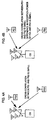
- Figs. 3A and 3B are schematic diagrams each showing a structure for allocating a channel to the second user in accordance with the cross correlation value of the reception signal coefficient vectors as in the case of Fig.2.
- Fig. 3A relates to the case where the cross correlation value of the reception signal coefficient vectors between users PS1 and PS2 is large. In this case, channel allocation to user PS2 is not possible.
- Fig. 3B relates to the case where the cross correlation value of the reception signal coefficient vectors between users PS1 and PS2 is small. In this case, channel allocation to user PS2 is basically possible. However, if channel allocation is performed only in accordance with the cross correlation value of the reception signal coefficient vectors, for example, user PS2 may be allocated to one of channels which are in a path multiplex relationship even if a difference in reception power of radio waves from users PS1 and PS2 is large. In other words, in the example shown in Fig. 2, user PS2 is allocated to channel (2, 1), but a sufficient communication quality is not ensured for PS2 with small reception power.
- channel allocation is performed in accordance not only with the cross correlation value of reception signal coefficient vectors but also with reception signal power, so that a sufficient communication quality is ensured for each user.
- Figs. 4A and 4B are schematic diagrams each showing a structure for allocating a channel to the second user in accordance with a cross correlation value of the reception signal coefficient vectors and the reception power.
- Fig. 4A relates to the case where the cross correlation value of the reception signal coefficient vectors between users PS1 and PS2 is small, and the reception power difference is large. In such a case, channel allocation to user PS2 is not possible.
- Fig. 4B relates to the case where the cross correlation value of the reception signal vectors between users PS1 and PS2 is small and the reception power difference is also small. In such a case, channel allocation to user PS2 is possible.
- a path multiplex is performed on user terminals having reception signal coefficient vectors of which cross correlation value is smaller than a prescribed first standard value and reception power difference is smaller than a prescribed second standard value. Thus, a good communication quality is ensured for any user terminal.
- reception signal coefficient vector calculator 1020 shown in Fig. 1 Next, the operation of reception signal coefficient vector calculator 1020 shown in Fig. 1 will be described.
- the reception signal is multiplied by a known user signal, for example, signal Srx 1 (t) from the first user, to obtain an ensemble average (a time average).
- E [ X ( t ) ⁇ Srx 1 *( t )] H 1 ⁇ E [ Srx 1 ( t ) ⁇ Srx 1 *( t )] + H 2 ⁇ E [ Srx 2 ( t ) ⁇ Srx 1 *( t )]+ E [ N ( t ) ⁇ Srx 1 *( t )]
- E[ ⁇ ] represents a time average and S*(t) represents a conjugate complex S(t). If the average is measured over a sufficient period of time, the following average value is obtained.
- E [ Srx 1 ( t ) ⁇ Srx 1 *( t )] 1
- E [ Srx 2 ( t ) ⁇ Srx 1 *( t )] 0
- E [ N ( t ) ⁇ Srx 1 *( t )] 0
- Equation (18) The value of equation (18) is 0 because there is no cross correlation between signals Srx 1 (t) and Srx 2 (t). Similarly, the value of equation (19) is 0 because there is no cross correlation between signal Srx 1 (t) and a noise signal N(t).
- reception signal coefficient H 1 transmitted from first user PS1 can be measured.
- reception signal coefficient vector H 2 of the signal transmitted from second user PS2 can be measured.
- reception signal power calculating device 1030 As in the conventional example described with reference to Figs. 14 and 15, assume that there are four antenna elements for simplification of description.
- the reception signal power from user PS1 can be calculated by the following equation (21).
- the reception signal power from the ith user PSi can be obtained by the following equation (22).
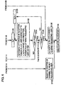
- Figs. 5 and 6 are flow charts shown in conjunction with the operation of channel allocation device 1050 shown in Fig. 1.
- channel allocation device 1050 when a channel allocation operation is started (step S100), channel allocation device 1050 initializes a value of a pointer variant i at 1, indicating a time slot that is possibly subjected to channel allocation (step S102). Successively, user number Ms currently connected to the ith time slot is determined (step S104). If user number Ms is 0, the process proceeds to step S103, the (i, Ms+1)th channel is allocated to a new user (step S130)) and the channel allocation operation ends (S134).
- a value of a pointer variant k is initialized at 1 (step S108).
- a cross relation value C of reception signal coefficient vector H (i,k) of the user connected to the (i, k)th channel and reception signal coefficient vector Hn of the newly requesting user is calculated in accordance with the following equation (step S110).
- C
- (X ⁇ Y) represents an inner product of vectors X and Y
- represents a magnitude of vector X.
- cross correlation value C and standard value Cstd (0 ⁇ Cstd ⁇ 1) are compared (step S112).
- step S112 If cross correlation value C is equal to or greater than standard value Cstd (step S112), variant i and total number Ns of time slots are compared (step S114). If variant i is equal to or smaller than total number Ns of time slots, variant i is incremented by 1 (step S116), and the process returns to step S104. On the other hand, if variant i is equal to or greater than total number Ns of time slots, channel allocation device 1050 rejects channel allocation to the new user (step S132), and the channel allocation operation ends (step S134).
- N 3
- step 112 if cross correlation value C is smaller than standard value Cstd (step 112), variant k and user number Ms of the ith time slot are compared (step 118). If variant k is smaller than user number Ms (step 118), variant k is incremented by 1 (step S120), and the process returns to step S110. More specifically, determination is made as to whether cross correlation value C of the reception signal coefficient of the newly requesting user and that of each user currently connected to the ith time slot is smaller than standard value Cstd.
- step S120 for measuring a difference in reception signal power of the currently connected user and the newly requesting user.
- a value of pointer variant k indicating a path that is possibly subjected to channel allocation is initialized at 1 and a difference Pdiff between reception power Pi, k of the user connected to the (i, k)th channel and reception signal power Pnew of the newly requesting user is calculated (step S122).
- step S124 If reception signal power difference Pdiff exceeds a prescribed standard value Pstd (step S124), variant i and total number Ns of time slots are compared (step S114). If variant i is equal to or smaller than total number Ns of time slots, variant i is incremented by 1 (step S116), and the process returns to step S104. On the other hand, if variant i exceeds total number Ns of time slots, channel allocation device 1050 rejects channel allocation to the new user (step S132) and the channel allocation operation ends (step S134).
- step S124 if difference Pdiff in reception signal power is smaller than standard value Pstd (step S124), variant k and number Ms of users connected to the ith time slot are compared (step S126). If variant k does not exceed Ms (step S126), variant k is incremented by 1 (step S128), and the process returns to step S122. In other words, determination is made as to if Pdiff is smaller than Pstd for every user connected to the ith time slot.
- step S130 the (i, Ms+1)th channel is allocated to the newly requesting user (step S130), and the channel allocation operation ends (step S134).
- channel allocation device 1050 enables channel allocation in accordance not only with the cross correlation value of reception signal coefficients but also with reception signal power, so that a sufficient communication quality can be ensured for each user who is in connection with a communication channel.
- Fig. 7 is a schematic block diagram showing a structure of transmission/reception system 1200 of a base station for PDMA according to a second embodiment of the present invention.
- Transmission/reception system 1200 differs from transmission/reception system 1000 of the first embodiment shown in Fig. 1 in that memory 1040 directly receives and stores values of weight vectors from adaptive arrays 1010.1 to 1010.M, and channel allocation device 1050 performs allocation in accordance with weight vector values in memory 1040 and reception signal power.
- memory 1040 directly receives and stores values of weight vectors from adaptive arrays 1010.1 to 1010.M
- channel allocation device 1050 performs allocation in accordance with weight vector values in memory 1040 and reception signal power.
- the other parts of the structure are the same as those of transmission/reception system 1000 of the first embodiment. Thus, the same parts are denoted by the same reference numerals, and description thereof will not be repeated.
- Figs. 8 and 9 are flow charts shown in conjunction with the operation of channel allocation device 1050 according to the second embodiment of the present invention.
- the channel allocation is performed in accordance with a cross correlation value of the reception signal coefficient vectors as well as a difference in reception signal power of the currently connected user and the newly requesting user.
- channel allocation is performed in accordance with a cross correlation value of weight vectors as well as a difference in reception signal power of the currently connected user and the newly requesting user.
- the channel allocation device 1050 of the second embodiment differs from that of the first embodiment in that cross correlation value C of weight vectors is calculated in step S210 of Fig. 8.
- cross correlation value C of reception signal coefficient vector W (i,k) of the user connected to the (i, k)th channel and reception signal coefficient vector Wn of the newly requesting user is calculated in accordance with the following equation.
- C
- the other parts of the structure are the same as those of the structure for a channel allocation process of the first embodiment, and therefore description thereof will not be repeated.
- channel allocation device 1050 channel allocation is performed in accordance not only with a cross correlation value of weight vectors but also with reception signal difference, so that a sufficient communication quality is ensured for each user who is in connection with the communication channel.
- a sufficient communication quality is ensured with a simpler structure as compared with transmission/reception system 1000 of the first embodiment.
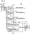
- Fig. 10 is a schematic block diagram showing a structure of a transmission/reception system 1400 of a base station for PDMA according to the third embodiment of the present invention.
- System 1400 differs from transmission/reception system 1000 of the first embodiment in that reception signal coefficient vector calculating device 1020 is replaced by an arrival direction estimating device 1060 for estimating an arrival direction of a reception signal, and in that channel allocation device 1050 performs channel allocation in accordance with the arrival direction of the reception signal and reception signal power stored in memory 1040.
- Other parts of the structure are the same as those of transmission/reception system 1000 of the first embodiment. Thus, the same parts are denoted by the same reference characters and description thereof will not be repeated.
- Figs. 11 and 12 are flow charts shown in conjunction with the operation of channel allocation device 1050 according to the third embodiment of the present invention.
- the channel allocation is performed in accordance with the cross correlation value of the reception signal coefficient vectors as well as the difference in reception signal power of the currently connected user and the newly requesting user.
- the channel allocation is performed in accordance with a difference in arrival direction as well as a difference in reception signal power of the currently connected user and the newly requesting user.
- a difference in arrival direction Ddiff is calculated.
- a step S312 if Ddiff exceeds a prescribed value, it is determined that interference between the currently connected user and the newly requesting user is small.
- the structure of the third embodiment is different from channel allocation device 1050 of the fist embodiment in which interference between the currently connected user and the newly requesting user is small if the cross correlation value of the reception signal coefficient vector is below a prescribed value.
- the term "a difference in arrival direction" can be defined as an angle formed by arrival directions.
- Such a structure enables channel allocation in accordance with not only the difference in arrival direction but also reception signal power in the operation of channel allocation device 1050, so that a sufficient communication quality is ensured for each user who is in connection with the communication channel.
Landscapes
- Engineering & Computer Science (AREA)
- Quality & Reliability (AREA)
- Computer Networks & Wireless Communication (AREA)
- Signal Processing (AREA)
- Mobile Radio Communication Systems (AREA)
- Radio Transmission System (AREA)
- Variable-Direction Aerials And Aerial Arrays (AREA)
Abstract
Description
Claims (12)
- A method of allocating transmission channels for multiple connection to a base station having array antennas to respective terminal devices in response to connection requests from a plurality of terminal devices, comprising:the step of searching connectable transmission channel candidates from empty transmission channels in accordance with a magnitude of cross correlation between a reception signal coefficient vector from a currently connected user and a reception coefficient vector from a user newly requesting user; andthe step of allocating said transmission channel from said transmission channel candidates to said newly requesting user in response to a fact that a difference in reception signal power of said currently connected user and said newly requesting user is smaller than a prescribed value.
- The transmission channel allocation method according to claim 1, wherein said transmission channel includes a plurality of time slots multiplexed in a direction of a time axis, each of said time slots has a plurality of path-divided channels, and said step of searching said transmission channel candidate includes the step of determining a connectable empty channel in accordance with a cross correlation value of said reception signal coefficient vectors of said currently connected user and said newly requesting user for every one of said time slots.
- The transmission channel allocation method according to claim 2, wherein a cross correlation value C of a reception signal coefficient vector H(i, k) of a user currently connected to the (i, k)th channel and a reception signal coefficient vector Hn of said newly requesting user is calculated in accordance with a following equation
- The transmission channel allocation method according to claim 1, wherein said transmission channel includes a plurality of time slots multiplexed in a direction of a time axis, each of said time slots has a plurality of path-divided channels, and said step of searching said transmission channel candidate includes the step of determining a connectable empty channel in accordance with a cross correlation value C of weight vectors of said currently connected user and said newly requesting user for every one of said time slots.
- The transmission channel allocation method according to claim 4, wherein said cross correlation value C of a reception signal coefficient W(i, k) of a user currently connected to the (i, k)th channel and a reception signal coefficient vector Wn of said newly requesting user is calculated in accordance with a following equation
- The transmission channel allocation method according to claim 1, wherein said transmission channel includes a plurality of time slots multiplexed in a direction of a time axis, each of said time slots has a plurality of path-divide channels, and said step of searching said transmission channel candidate includes the step of determining a connectable empty channel in accordance with an angular difference in arrival direction of reception signals from said currently connected user and said newly connected user for every one of said time slot.
- A radio apparatus (1000) for performing path division multiple access with respect to a plurality of terminal devices, comprising:array antennas (#1 to #N);a plurality of reception signal separating portions (1010.1 to 1010.M) for separating in real time reception signals by multiplying reception weight vectors corresponding to said terminal devices by said reception signals from said adaptive arrays;a reception signal power calculating portion (1030) respectively deriving reception signal power for each of said terminal devices; anda channel allocating portion (1050) determining a connectable transmission channel of empty transmission channels in accordance with a magnitude of cross correlation between reception signals from a currently connected user and a newly requesting user as well as a difference in reception signal power for allocation of said transmission channel to said newly requesting user.
- The radio apparatus according to claim 7, wherein said transmission channel includes a plurality of time slots multiplexed in a direction of a time axis, each of said time slot has a plurality of path-divided channels, and said channel allocating portion includes a reception signal vector calculating portion for deriving reception signal coefficient vectors of the currently connected user and the newly requesting user, and an allocation channel calculating portion for determining the connectable channel of said empty transmission channels in accordance with a cross correlation value of said reception signal coefficient vectors of said currently connected user and said newly requesting user for every one of said time slots.
- The radio apparatus according to claim 8, wherein said cross correlation value C of a reception signal coefficient vectors H(i, k) of a user currently connected to the (i, k)th channel and a reception signal coefficient vector Hn of said newly requesting user is calculated in accordance with the following equation
- The radio apparatus according to claim 7, wherein said transmission channel includes a plurality of time slots multiplexed in a direction of a time axis, each of said time slots has a plurality of path-divided channels, and said channel allocating portion includes an allocation channel calculating portion for determining the connectable transmission channel of the empty transmission channels in accordance with a cross correlation value of reception weight vectors of said currently connected user and said newly requesting user as well as a difference in reception signal power for every one of said time slots.
- The radio apparatus according to claim 10, wherein a cross correlation value C of a reception signal coefficient vector W(i, k) of a user currently connected to the (i, k)th channel and a reception signal coefficient vector Wn of said newly requesting user is calculated in accordance with the following equation
- The radio apparatus according to claim 7, wherein said transmission channel includes a plurality of time slots multiplexed in a direction of a time axis, each of said time slots has a plurality of path-divided channels, and said channel allocating portion includes an arrival direction estimating portion for deriving arrival directions of reception signals from said currently connected user and said newly requesting user, and an allocation channel calculating portion for determining the connectable transmission channel of the empty transmission channels in accordance with an angular difference in arrival direction of reception signals from said currently connected user and from said newly requesting user as well as a difference in said reception signal power for every one of said time slots.
Applications Claiming Priority (2)
| Application Number | Priority Date | Filing Date | Title |
|---|---|---|---|
| JP08007099A JP3229864B2 (en) | 1999-03-24 | 1999-03-24 | Transmission channel allocation method and wireless device using the same |
| JP8007099 | 1999-03-24 |
Publications (2)
| Publication Number | Publication Date |
|---|---|
| EP1041838A2 true EP1041838A2 (en) | 2000-10-04 |
| EP1041838A3 EP1041838A3 (en) | 2000-12-20 |
Family
ID=13707973
Family Applications (1)
| Application Number | Title | Priority Date | Filing Date |
|---|---|---|---|
| EP00106343A Withdrawn EP1041838A3 (en) | 1999-03-24 | 2000-03-23 | Transmission channel allocation method and radio apparatus using the same |
Country Status (4)
| Country | Link |
|---|---|
| US (1) | US6671516B1 (en) |
| EP (1) | EP1041838A3 (en) |
| JP (1) | JP3229864B2 (en) |
| CN (1) | CN1333536C (en) |
Families Citing this family (24)
| Publication number | Priority date | Publication date | Assignee | Title |
|---|---|---|---|---|
| JP3574057B2 (en) * | 2000-09-04 | 2004-10-06 | 三洋電機株式会社 | Wireless receiving system and method |
| JP3475166B2 (en) * | 2000-09-22 | 2003-12-08 | 三洋電機株式会社 | Radio base system and transmission timing control method |
| US7050480B2 (en) * | 2000-10-27 | 2006-05-23 | L3 Communications Corporation | Code assignment algorithm for synchronous DS-CDMA links with SDMA using estimated spatial signature vectors |
| US8611311B2 (en) | 2001-06-06 | 2013-12-17 | Qualcomm Incorporated | Method and apparatus for canceling pilot interference in a wireless communication system |
| US7079809B1 (en) * | 2002-02-07 | 2006-07-18 | Kathrein-Werke Kg | Systems and methods for providing improved wireless signal quality using diverse antenna beams |
| JP4014502B2 (en) * | 2002-12-27 | 2007-11-28 | 三洋電機株式会社 | Reception response characteristic holding method and wireless device using the same |
| JP4198552B2 (en) * | 2003-07-25 | 2008-12-17 | 株式会社エヌ・ティ・ティ・ドコモ | Wireless receiver, wireless transmitter, and impedance control method |
| CN100407582C (en) * | 2004-09-07 | 2008-07-30 | 华为技术有限公司 | Handheld device capable of prolonging working time and implementation method |
| CN100461731C (en) * | 2004-12-10 | 2009-02-11 | 三星电子株式会社 | Method for notifying service reception availability and determining active or inactive state |
| US8442441B2 (en) | 2004-12-23 | 2013-05-14 | Qualcomm Incorporated | Traffic interference cancellation |
| US8406695B2 (en) | 2004-12-23 | 2013-03-26 | Qualcomm Incorporated | Joint interference cancellation of pilot, overhead and traffic channels |
| US8422955B2 (en) | 2004-12-23 | 2013-04-16 | Qualcomm Incorporated | Channel estimation for interference cancellation |
| US7395084B2 (en) * | 2005-01-24 | 2008-07-01 | Sikorsky Aircraft Corporation | Dynamic antenna allocation system |
| FI20055211A0 (en) * | 2005-05-06 | 2005-05-06 | Nokia Corp | Radio resource management in FDMA |
| US8472877B2 (en) | 2005-10-24 | 2013-06-25 | Qualcomm Incorporated | Iterative interference cancellation system and method |
| US8385388B2 (en) | 2005-12-06 | 2013-02-26 | Qualcomm Incorporated | Method and system for signal reconstruction from spatially and temporally correlated received samples |
| US20090227261A1 (en) * | 2006-07-07 | 2009-09-10 | Nokia Corporation | Radio resource allocation mechanism |
| JP4773910B2 (en) * | 2006-08-10 | 2011-09-14 | 京セラ株式会社 | Base station apparatus and space division multiplexing method |
| FI20065698A0 (en) * | 2006-11-06 | 2006-11-06 | Nokia Corp | Allocation of radio resources and radio system |
| CN101669301B (en) | 2007-05-10 | 2012-12-05 | 上海贝尔阿尔卡特股份有限公司 | Method for uplink transmission scheduling of wireless communication system and relevant device |
| US20130109333A1 (en) * | 2011-07-25 | 2013-05-02 | Sebastian Rowson | Method and system for switched combined diversity with a modal antenna |
| US9769594B2 (en) * | 2015-01-30 | 2017-09-19 | Cassia Networks Inc. | Methods, devices and systems for increasing wireless communication range |
| CN106413052B (en) * | 2015-08-03 | 2019-05-31 | 电信科学技术研究院 | A kind of method, apparatus and system for distributing uplink power |
| CN111525285B (en) * | 2020-05-20 | 2021-04-02 | 西安黄河机电有限公司 | Thin-array antenna and design method thereof |
Family Cites Families (9)
| Publication number | Priority date | Publication date | Assignee | Title |
|---|---|---|---|---|
| US5515378A (en) * | 1991-12-12 | 1996-05-07 | Arraycomm, Inc. | Spatial division multiple access wireless communication systems |
| JP2518156B2 (en) * | 1993-07-19 | 1996-07-24 | 日本電気株式会社 | Channel allocation method for wireless communication system |
| JP2661533B2 (en) * | 1993-12-27 | 1997-10-08 | 日本電気株式会社 | Channel allocation method for mobile communication system |
| FR2738098B1 (en) | 1995-08-22 | 1997-09-26 | Thomson Csf | METHOD AND DEVICE FOR SPATIAL MULTIPLEXING OF DIGITAL RADIO-ELECTRIC SIGNALS EXCHANGED IN CELLULAR RADIOCOMMUNICATIONS |
| DE69604595T2 (en) * | 1995-08-22 | 2000-05-31 | Thomson-Csf, Paris | METHOD AND ARRANGEMENT FOR SPATIAL MULTIPLEXING / DEMULTIPLEXING OF RADIO SIGNALS IN AN SDMA MOBILE RADIO SYSTEM |
| US5886988A (en) * | 1996-10-23 | 1999-03-23 | Arraycomm, Inc. | Channel assignment and call admission control for spatial division multiple access communication systems |
| DE19713666C2 (en) | 1997-04-02 | 1999-01-14 | Siemens Ag | Method and device for channel allocation |
| JPH1132030A (en) | 1997-07-14 | 1999-02-02 | Sanyo Electric Co Ltd | PDMA communication method |
| US6466557B1 (en) * | 1997-07-14 | 2002-10-15 | Sanyo Electric Co., Ltd. | Transmission channel allocation method and allocation apparatus |
-
1999
- 1999-03-24 JP JP08007099A patent/JP3229864B2/en not_active Expired - Fee Related
-
2000
- 2000-03-22 US US09/533,362 patent/US6671516B1/en not_active Expired - Lifetime
- 2000-03-23 EP EP00106343A patent/EP1041838A3/en not_active Withdrawn
- 2000-03-24 CN CNB001083848A patent/CN1333536C/en not_active Expired - Fee Related
Also Published As
| Publication number | Publication date |
|---|---|
| CN1268818A (en) | 2000-10-04 |
| JP3229864B2 (en) | 2001-11-19 |
| EP1041838A3 (en) | 2000-12-20 |
| JP2000278204A (en) | 2000-10-06 |
| CN1333536C (en) | 2007-08-22 |
| US6671516B1 (en) | 2003-12-30 |
Similar Documents
| Publication | Publication Date | Title |
|---|---|---|
| US6671516B1 (en) | Transmission channel allocation method and radio apparatus using the same | |
| JP3167682B2 (en) | Radio apparatus having transmission directivity and control method therefor | |
| US6466557B1 (en) | Transmission channel allocation method and allocation apparatus | |
| JP4230535B2 (en) | Spectral efficient mass wireless communication system | |
| JP3233088B2 (en) | Directivity control antenna device | |
| AU2001296598B2 (en) | Method and apparatus for estimating downlink beamforming weights in a communications system | |
| EP1041839B1 (en) | Transmission channel allocation method and radio apparatus using the same | |
| US7071874B2 (en) | Radio terminal device, transmission directivity control method, and transmission directivity control program | |
| JPH09215052A (en) | Space division multiple access wireless communication system and channel allocation method in the same | |
| EP1429571B1 (en) | Radio base apparatus, communication channel allocation method, and allocation program | |
| US6754512B1 (en) | Wireless base station using adaptive array for spatial multiplexing | |
| JP3203231B2 (en) | Transmission channel allocating method and wireless device using the same | |
| US7269202B2 (en) | Radio apparatus, swap detecting method and swap detecting program | |
| JPH1132030A (en) | PDMA communication method | |
| US6449268B1 (en) | Digital radio communication system, PDMA radio base station reception system and weight vector calculation method | |
| JP3579363B2 (en) | Wireless receiving apparatus and wireless receiving method | |
| EP1351412A1 (en) | Radio device with transmission directivity, and control method and control program for the radio device | |
| JP2003069482A (en) | Wireless device | |
| JP3643805B2 (en) | Wireless base station equipment | |
| KR20020057594A (en) | Apparatus for smart antenna using phase estimation | |
| JP3773847B2 (en) | Wireless device and swap detection method | |
| JP2002185391A (en) | Antenna directivity control method for mobile phone terminal and mobile phone terminal | |
| JP4384775B2 (en) | Receiving machine |
Legal Events
| Date | Code | Title | Description |
|---|---|---|---|
| PUAI | Public reference made under article 153(3) epc to a published international application that has entered the european phase |
Free format text: ORIGINAL CODE: 0009012 |
|
| AK | Designated contracting states |
Kind code of ref document: A2 Designated state(s): DE FI FR GB SE |
|
| AX | Request for extension of the european patent |
Free format text: AL;LT;LV;MK;RO;SI |
|
| PUAL | Search report despatched |
Free format text: ORIGINAL CODE: 0009013 |
|
| AK | Designated contracting states |
Kind code of ref document: A3 Designated state(s): AT BE CH CY DE DK ES FI FR GB GR IE IT LI LU MC NL PT SE |
|
| AX | Request for extension of the european patent |
Free format text: AL;LT;LV;MK;RO;SI |
|
| RIC1 | Information provided on ipc code assigned before grant |
Free format text: 7H 04Q 7/38 A, 7H 04Q 7/36 B |
|
| 17P | Request for examination filed |
Effective date: 20010112 |
|
| AKX | Designation fees paid |
Free format text: DE FI FR GB SE |
|
| 17Q | First examination report despatched |
Effective date: 20071109 |
|
| GRAP | Despatch of communication of intention to grant a patent |
Free format text: ORIGINAL CODE: EPIDOSNIGR1 |
|
| RIC1 | Information provided on ipc code assigned before grant |
Ipc: H04W 72/08 20090101AFI20130131BHEP Ipc: H04W 16/28 20090101ALN20130131BHEP |
|
| RAP1 | Party data changed (applicant data changed or rights of an application transferred) |
Owner name: SANYO ELECTRIC CO., LTD. |
|
| STAA | Information on the status of an ep patent application or granted ep patent |
Free format text: STATUS: THE APPLICATION HAS BEEN WITHDRAWN |
|
| 18W | Application withdrawn |
Effective date: 20130624 |