EP1041814A2 - Image processing apparatus, and method, and storage medium - Google Patents
Image processing apparatus, and method, and storage medium Download PDFInfo
- Publication number
- EP1041814A2 EP1041814A2 EP00302286A EP00302286A EP1041814A2 EP 1041814 A2 EP1041814 A2 EP 1041814A2 EP 00302286 A EP00302286 A EP 00302286A EP 00302286 A EP00302286 A EP 00302286A EP 1041814 A2 EP1041814 A2 EP 1041814A2
- Authority
- EP
- European Patent Office
- Prior art keywords
- quantization
- pixel
- additional information
- interest
- image
- Prior art date
- Legal status (The legal status is an assumption and is not a legal conclusion. Google has not performed a legal analysis and makes no representation as to the accuracy of the status listed.)
- Granted
Links
Images







Classifications
-
- G—PHYSICS
- G06—COMPUTING OR CALCULATING; COUNTING
- G06T—IMAGE DATA PROCESSING OR GENERATION, IN GENERAL
- G06T1/00—General purpose image data processing
-
- H—ELECTRICITY
- H04—ELECTRIC COMMUNICATION TECHNIQUE
- H04N—PICTORIAL COMMUNICATION, e.g. TELEVISION
- H04N1/00—Scanning, transmission or reproduction of documents or the like, e.g. facsimile transmission; Details thereof
- H04N1/32—Circuits or arrangements for control or supervision between transmitter and receiver or between image input and image output device, e.g. between a still-image camera and its memory or between a still-image camera and a printer device
- H04N1/32101—Display, printing, storage or transmission of additional information, e.g. ID code, date and time or title
- H04N1/32144—Display, printing, storage or transmission of additional information, e.g. ID code, date and time or title embedded in the image data, i.e. enclosed or integrated in the image, e.g. watermark, super-imposed logo or stamp
- H04N1/32149—Methods relating to embedding, encoding, decoding, detection or retrieval operations
- H04N1/32203—Spatial or amplitude domain methods
-
- H—ELECTRICITY
- H04—ELECTRIC COMMUNICATION TECHNIQUE
- H04N—PICTORIAL COMMUNICATION, e.g. TELEVISION
- H04N1/00—Scanning, transmission or reproduction of documents or the like, e.g. facsimile transmission; Details thereof
- H04N1/32—Circuits or arrangements for control or supervision between transmitter and receiver or between image input and image output device, e.g. between a still-image camera and its memory or between a still-image camera and a printer device
- H04N1/32101—Display, printing, storage or transmission of additional information, e.g. ID code, date and time or title
- H04N1/32144—Display, printing, storage or transmission of additional information, e.g. ID code, date and time or title embedded in the image data, i.e. enclosed or integrated in the image, e.g. watermark, super-imposed logo or stamp
- H04N1/32149—Methods relating to embedding, encoding, decoding, detection or retrieval operations
- H04N1/32203—Spatial or amplitude domain methods
- H04N1/32256—Spatial or amplitude domain methods in halftone data
Definitions
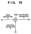
- Fig. 16 illustrates the conventional additional information embedding method.
- image information A and additional information B are multiplexed via an adder 1601 to generate multiplexed information C.
- the adder 1601 may add information in the real space of the image information A or may transform the image information A into that in the frequency domain using, e.g., Fourier transformation, or the like and may then synthesize the additional information B in the high-frequency range of the converted information.
- image information which is distributed on, e.g., the Internet, can also be decoded via digital filters for improving image quality such as edge emphasis, smoothing, and the like, as long as it has some noise resilience.
- ink-jet printers can express several gray levels per color using inks with lower dye densities or by variably controlling the dot sizes to be output, but cannot express a photo-quality image unless a pseudo halftone process is used.
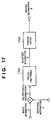
- Fig. 17 illustrates an example that executes a pseudo halftone process upon conventional additional information multiplexing. That is, in addition to the arrangement shown in Fig. 16, the multiplexed information is converted into quantized information D by a pseudo halftone process 1701, and the converted information is printed out onto a recording sheet by a printer output 1702, thus obtaining printed information E that has deteriorated considerably.
- the multiplexing method shown in Fig. 17 is not suitable. In other words, an additional information multiplexing method that fully utilizes the-characteristics of the pseudo halftone process is needed.
- a method of multiplexing additional information using a color dither pattern method is known.
- this method deterioration of image quality upon switching the dither matrices cannot be avoided as in the above example.
- a larger number of pieces of additional information can be multiplexed, but color tincture changes since the layout of color components changes, and image quality deteriorates considerably in a solid portion. Also, decoding becomes more harder to attain.
- the present invention has been made to solve the above-mentioned problems and has as its object to provide an image processing apparatus and method, which can multiplex additional information onto image information while suppressing deterioration of image quality, and can easily decode the additional information, and a storage medium.
- an image processing apparatus for multiplexing additional information onto image information, comprising quantization means for quantizing a pixel of interest of the image information by a pseudo halftone process based on error diffusion, and control means for controlling a quantization value of the pixel of interest with quantization values of a plurality of pixels including the pixel of interest forming a specific pattern indicating the additional information.
- the specific pattern is a pattern which is not easily generated by the quantization means.
- an image processing apparatus in each of the embodiments is efficiently implemented as a printer driver in a computer that creates image information to be output to a printer information, but may be effectively built in a copying machine, facsimile apparatus, printer main body, or the like as hardware or software.
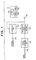
- reference numeral 10 denotes a controller which includes a CPU 10a, ROM 10b, RAM 10c, and the like, and controls operations and processes of the individual building components to be described below. Especially, the CPU 10a controls multiplexing and associated processes in accordance with programs pre-stored in the ROM 10b using the RAM 10c as a work memory.
- Reference numeral 103 denotes a quantization unit for computing the quantization value of the pixel of interest with reference to the code of additional information and the quantization results of a plurality of pixels which have already been finally quantized. Note that the quantization method in the quantization unit 103 will be described in detail later.
- Reference numeral 104 denotes a quantization value determination unit that determines a final quantization value on the basis of both the quantization value after pseudo halftoning in the pseudo halftone processing unit 101, and that after quantization in the quantization unit 103.
- This quantization result is sent to a printer engine via an output terminal 105 as a multiplexing result of additional information onto image information, and an image is formed on a recording sheet.
- reference numeral 200 denotes an adder, which adds the value of the pixel of interest of the input image information and a quantization error distributed from already binarized, surrounding pixels.
- the sum is compared with a threshold value set in advance by a comparator 201, and when the sum is larger than the threshold value, "1" is output; otherwise, "0" is output, thus quantizing the pixel value.
- the gray level of a given pixel is expressed by, e.g., 8-bit precision, it is a common practice to express it using "255" as a maximum value and "0" as a minimum value.
- the quantization value is "1"
- a dot (ink, toner, or the like) is printed on a recording sheet.
- Reference numeral 202 denotes a subtractor which computes any error between the quantization result output from the comparator 201 and the sum output from the adder 200, and outputs the error to an error distribution operating section 203.
- the error distribution operating section 203 distributes the error to surrounding pixels which are to undergo quantization next.
- an error distribution table 204 which is experimentally set on the basis of relative distances to the pixel of interest is prepared in advance, and the error is distributed to the pixels on the basis of the distribution ratios in the distribution table 204.
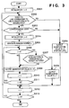
- step S301 variable i is initialized, variable i counts the vertical address.
- step S302 discrimination using the address value i is made, i.e., it is checked if address i indicates a line in which a code is to be embedded. Assuming that additional information for 40 bits is embedded in a block defined by N vertical pixels and M horizontal pixels, addresses for "40 + ⁇ " lines of those for all N lines in the vertical direction of that block are used to embed codes. Note that a is required as marker codes and the like indicating the start and end of codes. In this case, rules indicating which "40 + ⁇ " lines of the N lines are to be used must be recognized by both the encoder and decoder sides. For example, a rule for embedding codes every n-th lines or the like may be set. In this case, the value n is preferably large to some extent, so that embedded codes are not visually conspicuous.
- Figs. 4A and 4B show an example of the target pattern in this embodiment.
- Fig. 4A shows a pixel layout in a given block of the image information, i.e., the window, * indicates the pixel of interest, and pixels A, B, C, D, and E are those which have already undergone final binarization.
- Fig. 4B shows a target pattern example. If pixels A to E in the window shown in Fig. 4A assume values in the target pattern, it is determined that the pattern in the window matches the target pattern. In the example shown in Figs. 4A and 4B, since there are five pixels to be referred to, combinations for 5 bits are available as patterns of the reference pixels. The actual pattern of quantization values around the pixel of interest is one of the combinations for 5 bits, and it is checked in step S307 above if the surrounding pixel pattern is equal to the target pattern set in advance.
- the quantization value determination unit 104 will be described below.
- the quantization value determination unit 104 comprises a simple OR gate. Hence, a pixel which is quantized to "1" as the quantization result of either the pseudo halftone processing unit 101 or quantization unit 103 is finally output as "1". More specifically, a new quantization value "1" is appended to only a pixel in which a code "1" is embedded by the quantization unit 103 in addition to pixels that have undergone pseudo halftoning. Appending of the quantization value amounts to embedding of a code of additional information in this embodiment.
- Fig. 5 shows a state wherein codes are multiplexed in a block. Assume that the broken lines in Fig. 5 indicate those in which codes are to be embedded. By embedding a plurality of codes in a single line, they indicate marker codes which serve as the start and end codes of the block.
- codes of all x bits from the first to x-th bits are embedded in fixed lines.
- information indicating lines used in embedding must be recognized by both the encoder and decoder sides.
- An end marker code is embedded at the end of the block. Note that either the start or end marker code can be omitted. More specifically, the decoder side can detect a region in which the codes are multiplexed.
- a random number is used in the column direction.
- the present invention is not limited to such specific example, and a random number may be used in the line direction. That is, the decoder side must accurately recognize the embedded positions by regularly determining the code embedded positions in at least one direction or providing a key that specifies the embedded positions.
- the arrangement that implements the multiplexing process of this embodiment has been described.
- the gist of this embodiment lies in that a texture which cannot normally be generated by pseudo halftoning is artificially generated by a combination of quantization values, and a 1-bit code is expressed by the presence/absence of that texture. That is, this embodiment is characterized in that the pixel of interest is quantized to "1" upon detecting the target pattern shown in Fig. 4B in an image, thus artificially generating a texture of a run of "1"s.
- error diffusion is known as a quantization method that generates a very unique texture.
- generation of a chain-like texture that the observer visually finds disturbing is a serious problem of error diffusion. For this reason, many proposals for preventing such disturbing texture have been made.
- texture patterns include those that can be generated, and those that cannot be generated.
- a diffusion matrix shown in Fig. 6 is used as the error distribution table 204, when a pixel immediately before the pixel of interest indicated by * is quantized to "1", since a negative quantization error is generated, it becomes harder to quantize the neighboring pixel of interest to "1". Therefore, upon decoding codes appended by this embodiment, if a highlight (low-density range) solid portion can be detected, since a quantization value pattern in which both the horizontally neighboring pixels assume "1" cannot be normally generated, that pattern can be recognized as a code if it is detected.
- both the neighboring pixels never assume "1" in a highlight solid portion.
- the code embedded as successive dots in this embodiment can be decoded in at least the highlight solid portion. Since this embodiment has as its object to prevent securities such as banknotes, revenue stamps, and the like from being forged, a target image always includes a highlight solid portion.
- color information such as YMCK information or the like, one of four colors separated into color components is highly likely to be a highlight solid portion as a result of a process such as UCR (undercolor removal) or the like. Hence, this embodiment can sufficiently achieve that object.
- a code is expressed by a texture which is not easily generated in a solid portion of an image
- additional information can be multiplexed onto image information while suppressing deterioration of image quality. Also, multiplexed additional information can be easily decoded without using any expensive, precision device.
- the quantization process in the second embodiment will be described in detail below with reference to the flow chart shown in Fig. 7.
- the quantization value is assumed to be a binary value and additional information is embedded in a block consisting of N ⁇ M pixels in image information as in the first embodiment.
- the information size to be embedded in one line in the block is 1 bit.
- the same step numbers denote the same processes as those in the flow chart shown in Fig. 3 described in the first embodiment, and a detailed description thereof will be omitted.
- step S303 if it is determined in step S303 that the code to be embedded is "1", pattern A which is registered in advance is set as a target pattern in step S701; if it is determined in step S303 that the code is "0", pattern B which is registered in advance is set as a target pattern in step S706.
- the subsequent processes are the same as those in the first embodiment.
- Figs. 8A to 8C show example of patterns A and B set as the target pattern in the second embodiment.
- Fig. 8A shows a pixel layout in the window, * indicates the pixel of interest, and pixels A to H are surrounding pixels which have already undergone final binarization, and have combinations of values for 8 bits.
- Figs. 8B and 8C respectively show the examples of patterns A and B, and values of pixels at positions indicated by "-" can be any values.
- quantization value Q "1" is set at “1" not only when the code is “1” but also when it is “0". That is, upon embedding codes, all quantization values Q are set at "1".
- the decoder side can determine based on the pattern difference if the embedded code is "1" or "0". That is, the first embodiment mentioned above embeds 1-bit information by the presence/absence of a texture, as shown in Fig. 3, while the second embodiment embeds a code by changing the pattern of a texture to be generated. In the example shown in Figs. 8A to 8C, a pattern in which "1"s successively appear horizontally is set as a code "1", and a pattern in which "1"s successively appear vertically is set as a code "0".
- the decoder side should recognize and decode a highlight solid portion or a solid portion of a high-density portion as in the first embodiment described above.
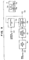
- Fig. 9 shows a schematic arrangement of a multiplexer according to the third embodiment.
- the same reference numerals in Fig. 9 denote the same parts as in Fig. 1 in the first embodiment described above, and a detailed description thereof will be omitted.
- a characteristic feature of the third embodiment lies in that a noise removing unit 901 is inserted before the pseudo halftone processing unit 101.
- the noise removing unit 901 removes small noise present in an image using a filter.
- the noise removal method is not particularly limited. For example, a window may be formed by pixels that surround the pixel of interest, and if only the pixel of interest has a pixel value different from those of the surrounding pixels, it may be determined as noise, and the pixel value of the pixel of interest may be changed.
- other known methods may be used.
- quantization method in the quantization unit 103 can be based on the operation sequence shown in the flow chart of Fig. 3 or 7 in the first or second embodiment described above.
- the third embodiment embeds a code in an image as a texture pattern, and the decoder side decodes information by detecting the embedded code. That is, as a pattern to be artificially generated, a pattern which is not easily generated in a corresponding density range by the pseudo halftone process alone is required.
- a value "1" is not easily generated for two successive pixels in a highlight solid portion.
- the decoder side detects a pattern of successive "1"s, it can hardly determine if the detected pattern is generated by noise or by artificially embedding a code.
- a low-pass filter may be connected in place of the noise removing unit 901.
- an optimal filter is preferably selected by experiments.
- the input terminal 100 receives only image information via an input device such as a scanner or the like, and artificial image information such as a character/line image, or the like is preferably input via another processing route so as not to undergo any noise removal.
- Fig. 10 is a block diagram showing a schematic arrangement of a multiplexer according to the fourth embodiment.
- Reference numeral 100 denotes an input terminal which inputs multi-level image information.
- Reference numeral 1001 denotes a pseudo halftone processing unit which executes pseudo halftoning of image information input from the input terminal 100 to convert the information to quantization levels smaller than the number of input gray levels and to reproduce tone by dot area modulation using the quantization values of a plurality of pixels.
- This quantization result is sent to a printer engine via an output terminal 105 as a multiplexing result of additional information onto image information, and an image is formed on a recording sheet.
- the detailed arrangement of the pseudo halftone processing unit 1001 is the same as that shown in Fig. 2 in the first embodiment.
- Reference numeral 102 denotes an input terminal for inputting required additional information to be embedded in image information.
- the additional information may include various kinds of information that pertain to the output state upon outputting an image onto a recording sheet such as the manufacturer name, model name, machine number, and the like of an output device.
- Reference numeral 1002 denotes a pseudo halftone condition change unit which changes the pseudo halftone processing condition in the pseudo halftone processing unit 1001 with reference to the code of additional information and the quantization results of a plurality of pixels that have already undergone final quantization.
- Fig. 11 is a flow chart showing the operation sequence of the pseudo halftone condition change unit 1002.
- the quantization value is assumed to be a binary value and additional information is embedded in a block consisting of N ⁇ M pixels in image information as in the first embodiment.
- the information size to be embedded in one line in the block is 1 bit.
- the same step numbers denote the same processes as those in the flow chart shown in Fig. 3 described in the first embodiment, and a detailed description thereof will be omitted.
- the pseudo halftone condition change unit 1002 changes the threshold value TH in this way, the pseudo halftone processing unit 1001 can appropriately embed additional information by executing only normal error diffusion.
- a code can be multiplexed while preserving the local density.
- Fig. 12 shows a schematic arrangement of a multiplexer according to the fifth embodiment.
- the same reference numerals in Fig. 12 denote the same parts as those in Fig. 1 in the first embodiment, and a detailed description thereof will be omitted.
- reference numeral 1201 denotes a quantization unit for computing the quantization value of the pixel of interest with reference to the code of additional information and the quantization results of a plurality of pixels which have already been finally quantized.
- the fifth embodiment is characterized in that the pixel of interest before the pseudo halftone process and its surrounding pixel values are input to the quantization unit 1201.
- a texture which is not easily generated in a corresponding density range is generated as an artificial texture pattern, and is multiplexed.
- This multiplexing method is premised on that a block of image information, which serves as one unit of a code to be multiplexed is a solid portion having a uniform density. More specifically, the aforementioned multiplexing method is effective for a solid portion of an image.
- a block of image information often includes an edge or a plurality of density ranges.
- the number of gray levels that can be expressed are grouped into a plurality of density ranges, and target patterns in units of density ranges are preferably held in advance as a table.
- the quantization result may be forcibly set at "0" to achieve high-speed processes.
- the decoder side must detect the image density, and detect the target pattern in correspondence with the density. Hence, when the table is used upon multiplexing, it is effective to use a similar table upon decoding.
- the target pattern is set in correspondence with the image density.
- it is effective to combine the fifth embodiment with the fourth embodiment. More specifically, when the quantization threshold value is set in correspondence with the image density, the same effect as that obtained upon switching the target pattern is obtained in practice.
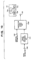
- Fig. 13 shows a schematic arrangement of a multiplexer according to the sixth embodiment.
- the same reference numerals in Fig. 13 denote the same parts as those in Fig. 1 in the first embodiment, and a detailed description thereof will be omitted.
- reference numeral 1301 denotes a quantization layout change unit for changing the layout of quantization values that have already undergo the pseudo halftone process, on the basis of quantization values around the pixel of interest after the pseudo halftone process, and input additional information.
- Fig. 14 is a flow chart showing the operation sequence in the quantization layout change unit 1301, i.e., the quantization process in the sixth embodiment.
- the quantization value is assumed to be a binary value and additional information is embedded in a block consisting of N ⁇ M pixels in image information as in the first embodiment. Note that the information size to be embedded in one line in the block is 1 bit.
- the same step numbers denote the same processes as those in the flow chart shown in Fig. 3 described in the first embodiment, and a detailed description thereof will be omitted.
- step S302 if it is determined in step S302 that the line of interest is a line in which a code is not embedded, and if it is determined in step S303 that the code to be embedded is "0", the flow jumps to step S312 to start the process for the next line. That is, in the currently processing line, the layout of already quantized pixels remains the same.
- step S306 It is checked in step S306 if the value of horizontal address counter j is larger than random number a. If YES in step S306, it is checked in step S307 if the pattern in a window that refers to a plurality of already binarized pixels matches a predetermined target pattern as in the first embodiment. If YES in step S307, the neighboring range of surrounding pixels is searched to find a pixel quantized to "1" in step S1401. This search is made within a predetermined range in turn from a pixel closer to the pixel of interest. Note that pixels corresponding to neighboring "1"s present in the target pattern are excluded from search targets. Note that the search range must be smaller than the spacing of lines in which codes are embedded.
- step S1402 The quantization value of the found pixel is changed from “1" to "0” in step S1402, and the quantization value of the pixel of interest is conversely changed from “0" to "1” in step S1403. That is, in steps S1402 and 1403, the layout of quantization values of the pixel of interest and surrounding pixels is changed. After the layout of quantization values is changed, the flow advances to step S312 to count up vertical address counter i, thus starting the process for the next line.
- step S306 the flow advances to step S310 to count up horizontal address counter j.
- the sixth embodiment is characterized in that a code is embedded by changing only the pixel layout without changing the density value itself. Note that the quantizatlon layout change process may be done synchronously or asynchronously with error diffusion.
- Figs. 15A and 15B show a state wherein the quantization layout is changed in the sixth embodiment.
- Fig. 15A shows the output from the pseudo halftone processing unit 101, i.e., the state of quantization values after the error diffusion process
- Fig. 15B shows the output from the quantization layout change unit 1301, i.e., the state of quantization values after the layout has been changed.
- reference numeral 1501 denotes the pixel of interest.
- the search range is set to include, e.g., 24 pixels in the vicinity of the pixel of interest (5 ⁇ 5 pixels having the pixel of interest as the center).
- Figs. 15A and 15B the same effect as that obtained by moving a pixel 1502 which has a value "1" in the search range to the position of the pixel 1501 of interest by changing the quantization layout is obtained.
- each of the above embodiments has exemplified two gray levels (the quantization value assumes "0" or "1"), but the present invention is also effective for a larger number of gray levels.
- a 1-bit code is embedded per line of a block, but the present invention is not limited to this.
- a position where a code is to be embedded in one line is controlled using a random number.
- the present invention is not limited to such specific example. For example, a position where a code is to be embedded in one line may be set in advance, and such positions may be set regularly.
- the functions of the above-mentioned embodiments may be implemented by some or all of actual processing operations executed by a CPU or the like arranged in a function extension board or a function extension unit, which is inserted in or connected to the computer, after the program code read out from the storage medium is written in a memory of the extension board or unit.
- the present invention can be implemented by a computer program operating on a computer processor.
- An aspect of the present invention thus provides a storage medium storing processor implementable instructions for controlling a processor to carry out the method as hereinabove described.
- the computer program can be obtained in electronic form for example by downloading the code over a network such as the internet.
- an electrical signal carrying processor implementable instructions for controlling a processor to carry out the method as hereinbefore described.
Landscapes
- Engineering & Computer Science (AREA)
- Multimedia (AREA)
- Signal Processing (AREA)
- Physics & Mathematics (AREA)
- General Physics & Mathematics (AREA)
- Theoretical Computer Science (AREA)
- Image Processing (AREA)
- Editing Of Facsimile Originals (AREA)
- Facsimile Image Signal Circuits (AREA)
- Holo Graphy (AREA)
- Measuring And Recording Apparatus For Diagnosis (AREA)
- Ultra Sonic Daignosis Equipment (AREA)
Abstract
Description
Claims (22)
- An image processing apparatus for multiplexing additional information onto image information, characterized by comprising:quantization means for quantizing a pixel of interest of the image information by a pseudo halftone process based on error diffusion; andcontrol means for controlling a quantization value of the pixel of interest with quantization values of a plurality of pixels including the pixel of interest forming a specific pattern indicating the additional information.
- The apparatus according to claim 1, characterized in that the specific pattern is a pattern which is not easily generated by said quantization means.
- The apparatus according to claim 1, characterized in that said control means comprises:additional information quantization means for setting a quantization value of the pixel of interest on the basis of surrounding pixels, which have already been quantized by said quantization means, and the additional information; anddetermination means for determining the quantization value of the pixel of interest on the basis of quantization results of said quantization means and said additional information quantization means.
- The apparatus according to claim 3, characterized in that said quantization means and said additional information quantization means make binary quantization, andsaid determination means determines the quantization value of the pixel of interest by ORing the quantization results of said quantization means and said additional information quantization means.
- The apparatus according to claim 3, characterized in that said additional information quantization means quantizes the pixel of interest by multiplexing the additional information thereon when quantization values of the surrounding pixels form a predetermined pattern.
- The apparatus according to claim 3, characterized in that said additional information quantization means sets the quantization value of the pixel of interest also with reference to pixel values around the pixel of interest before quantization by said quantization means.
- The apparatus according to claim 1, characterized in that said control means forms the specific pattern by controlling a quantization condition of said quantization means on the basis of the additional information.
- The apparatus according to claim 7, characterized in that said control means forms the specific pattern by controlling a quantization condition of said quantization means further on the basis of surrounding pixels that have already been quantized by said quantization means.
- The apparatus according to claim 7, characterized in that said control means controls a quantization threshold value in the pseudo halftone process executed by said quantization means.
- The apparatus according to claim 7, characterized in that said control means controls the quantization condition of said quantization means with reference to pixel values around the pixel of interest before being quantized by said quantization means.
- The apparatus according to claim 1, characterized in that said control means forms the specific pattern by controlling a layout of the pixel of interest and surrounding pixels quantized by said quantization means, on the basis of the additional information.
- The apparatus according to claim 11, characterized in that said control means controls the pixel layout after quantization with reference to pixel values around the pixel of interest before being quantized by said quantization means.
- The apparatus according to claim 1, characterized in that said control means forms a plurality of types of specific patterns.
- The apparatus according to claim 1, characterized in that said control means controls a forming position of the specific pattern on the basis of a random number.
- The apparatus according to claim 1, characterized in that said control means forms the specific pattern to have regularity in at least one of column and line directions.
- The apparatus according to claim 1, characterized by further comprising noise removing means for removing a noise component of the image information, andin that said quantization means quantizes the image information from which noise has been removed by said noise removing means.
- An image processing method for multiplexing additional information onto image information, characterized by comprising:the quantization step of quantizing a pixel of interest of the image information by a pseudo halftone process based on error diffusion; andthe control step of controlling a quantization value of the pixel of interest with quantization values of a plurality of pixels including the pixel of interest forming a specific pattern indicating the additional information.
- A storage medium which stores a program code of an image process for multiplexing additional information onto image information, said program code characterized by having at least:a code of the quantization step of quantizing a pixel of interest of the image information by a pseudo halftone process based on error diffusion; anda code of the control step of controlling a quantization value of the pixel of interest with quantization values of a plurality of pixels including the pixel of interest forming a specific pattern indicating the additional information.
- A method of processing image data for digital watermarking of an image, the method comprising the steps of;processing image data using an error diffusion pseudo halftone process to produce quantized data; andinserting additional quantized data representative of additional information into the quantized data such that resulting output data comprises patterns of quantized data which are uncharacteristic of results of the pseudo halftone process and which are representative of the additional information.
- A method as claimed in claim 19 wherein the output data is in binary form and wherein said patterns in the resultant image comprise successively output dots.
- A computer program comprising processor implementable instructions for carrying out a method as claimed in any of claims 17, 19 and 20.
- A signal representative of processor implementable instructions for carrying out a method as claimed in any of claims 17, 19 and 20.
Applications Claiming Priority (2)
| Application Number | Priority Date | Filing Date | Title |
|---|---|---|---|
| JP9007199 | 1999-03-30 | ||
| JP09007199A JP3639742B2 (en) | 1999-03-30 | 1999-03-30 | Image processing apparatus and method |
Publications (3)
| Publication Number | Publication Date |
|---|---|
| EP1041814A2 true EP1041814A2 (en) | 2000-10-04 |
| EP1041814A3 EP1041814A3 (en) | 2002-02-13 |
| EP1041814B1 EP1041814B1 (en) | 2011-05-11 |
Family
ID=13988312
Family Applications (1)
| Application Number | Title | Priority Date | Filing Date |
|---|---|---|---|
| EP00302286A Expired - Lifetime EP1041814B1 (en) | 1999-03-30 | 2000-03-21 | Image processing apparatus, and method, and storage medium |
Country Status (7)
| Country | Link |
|---|---|
| US (1) | US6750983B1 (en) |
| EP (1) | EP1041814B1 (en) |
| JP (1) | JP3639742B2 (en) |
| KR (1) | KR100357679B1 (en) |
| CN (1) | CN1230788C (en) |
| AT (1) | ATE509468T1 (en) |
| SG (1) | SG97869A1 (en) |
Cited By (1)
| Publication number | Priority date | Publication date | Assignee | Title |
|---|---|---|---|---|
| US7072522B2 (en) | 2001-09-26 | 2006-07-04 | Canon Kabushiki Kaisha | Image processing apparatus and method |
Families Citing this family (17)
| Publication number | Priority date | Publication date | Assignee | Title |
|---|---|---|---|---|
| US7372594B1 (en) | 1999-09-30 | 2008-05-13 | Canon Kabushiki Kaisha | Image processing apparatus and method, and storage medium |
| JP4310031B2 (en) * | 2000-07-11 | 2009-08-05 | キヤノン株式会社 | Image processing apparatus, image processing method, and storage medium |
| JP3587168B2 (en) * | 2001-01-23 | 2004-11-10 | 日本ビクター株式会社 | Digital watermark information embedding device, embedding method, digital watermark information reproducing device and reproducing method |
| US7187806B2 (en) * | 2001-08-23 | 2007-03-06 | Hewlett-Packard Development Company, L.P. | System and method for embedding information within a printed image using block error diffusion halftoning |
| US7564588B2 (en) * | 2002-01-24 | 2009-07-21 | Ricoh Company, Ltd. | Image forming device, image forming method, and recording medium that provide multi-level error diffusion |
| JP2004120122A (en) * | 2002-09-24 | 2004-04-15 | Sharp Corp | Image processing device |
| JP4192900B2 (en) * | 2005-02-08 | 2008-12-10 | ソニー株式会社 | Quantization accuracy reproduction method, quantization accuracy reproduction device, imaging device, information processing device, and program |
| KR100814029B1 (en) * | 2006-03-30 | 2008-03-14 | 순천향대학교 산학협력단 | Digital Watermarking Method in Halftone Image |
| JP2008097537A (en) * | 2006-10-16 | 2008-04-24 | Konica Minolta Business Technologies Inc | Image forming device, image processing method and image processing program |
| JP4922205B2 (en) * | 2007-08-17 | 2012-04-25 | 株式会社東芝 | Image processing method and image processing apparatus |
| JP5219591B2 (en) * | 2008-04-02 | 2013-06-26 | キヤノン株式会社 | Image processing apparatus and method |
| JP2009253472A (en) * | 2008-04-02 | 2009-10-29 | Canon Inc | Image processing apparatus, and method thereof |
| JP5825857B2 (en) | 2011-06-03 | 2015-12-02 | キヤノン株式会社 | Image forming apparatus, image forming method, and program |
| JP5825856B2 (en) | 2011-06-03 | 2015-12-02 | キヤノン株式会社 | Image forming apparatus, image forming method, and program |
| US9087291B2 (en) | 2013-10-01 | 2015-07-21 | Canon Kabushiki Kaisha | Image processing apparatus and method setting thresholds of dither patterns based on density range and generating binary data depending on thresholds of target pixels |
| JP6312397B2 (en) | 2013-10-01 | 2018-04-18 | キヤノン株式会社 | How to create a dither pattern |
| US9210292B2 (en) | 2013-10-01 | 2015-12-08 | Canon Kabushiki Kaisha | Image processing apparatus and method using different dither patterns for different inks and selecting a quantization process for each ink |
Family Cites Families (15)
| Publication number | Priority date | Publication date | Assignee | Title |
|---|---|---|---|---|
| JP2810395B2 (en) | 1989-02-10 | 1998-10-15 | キヤノン株式会社 | Image processing device |
| US5305116A (en) * | 1990-04-06 | 1994-04-19 | Canon Kabushiki Kaisha | Image transmission device |
| US5499111A (en) | 1991-08-06 | 1996-03-12 | Matsushita Graphic Communication Systems, Inc. | Image signal processing apparatus |
| US5822462A (en) | 1991-09-11 | 1998-10-13 | Canon Kabushiki Kaisha | Image processing apparatus |
| JPH05103309A (en) * | 1991-10-04 | 1993-04-23 | Canon Inc | Method and device for transmitting information |
| US5457540A (en) * | 1992-01-06 | 1995-10-10 | Canon Kabushiki Kaisha | Image processing method and apparatus in which identification information is added based on image density |
| US5331429A (en) * | 1992-02-07 | 1994-07-19 | Levien Raphael L | Digital generation of halftone images with error diffusion and frequency matched periodic screen rulings |
| JP3274227B2 (en) | 1993-05-24 | 2002-04-15 | キヤノン株式会社 | Image processing method and apparatus |
| EP0766468B1 (en) * | 1995-09-28 | 2006-05-03 | Nec Corporation | Method and system for inserting a spread spectrum watermark into multimedia data |
| EP0707419A2 (en) | 1995-11-10 | 1996-04-17 | Sinar AG Schaffhausen | Method for the generation of a view finder image and still picture camera |
| US6185312B1 (en) * | 1997-01-28 | 2001-02-06 | Nippon Telegraph And Telephone Corporation | Method for embedding and reading watermark-information in digital form, and apparatus thereof |
| US5875248A (en) * | 1997-02-25 | 1999-02-23 | International Business Machines Corporation | Method of counterfeit detection of electronic data stored on a device |
| KR19980086811A (en) * | 1997-05-08 | 1998-12-05 | 니시무로 타이조 | Apparatus, method and recording medium for embedding and reproducing additional information |
| JP3642158B2 (en) * | 1997-06-25 | 2005-04-27 | ソニー株式会社 | Image encoding device, image encoding method, image decoding device, image decoding method, and transmission method |
| JP3132456B2 (en) * | 1998-03-05 | 2001-02-05 | 日本電気株式会社 | Hierarchical image coding method and hierarchical image decoding method |
-
1999
- 1999-03-30 JP JP09007199A patent/JP3639742B2/en not_active Expired - Fee Related
-
2000
- 2000-03-21 AT AT00302286T patent/ATE509468T1/en not_active IP Right Cessation
- 2000-03-21 EP EP00302286A patent/EP1041814B1/en not_active Expired - Lifetime
- 2000-03-22 SG SG200001601A patent/SG97869A1/en unknown
- 2000-03-27 US US09/535,545 patent/US6750983B1/en not_active Expired - Fee Related
- 2000-03-29 KR KR1020000016137A patent/KR100357679B1/en not_active Expired - Fee Related
- 2000-03-30 CN CNB001048406A patent/CN1230788C/en not_active Expired - Fee Related
Cited By (1)
| Publication number | Priority date | Publication date | Assignee | Title |
|---|---|---|---|---|
| US7072522B2 (en) | 2001-09-26 | 2006-07-04 | Canon Kabushiki Kaisha | Image processing apparatus and method |
Also Published As
| Publication number | Publication date |
|---|---|
| KR20010020695A (en) | 2001-03-15 |
| EP1041814B1 (en) | 2011-05-11 |
| JP3639742B2 (en) | 2005-04-20 |
| SG97869A1 (en) | 2003-08-20 |
| ATE509468T1 (en) | 2011-05-15 |
| JP2000287062A (en) | 2000-10-13 |
| US6750983B1 (en) | 2004-06-15 |
| CN1270372A (en) | 2000-10-18 |
| KR100357679B1 (en) | 2002-10-18 |
| EP1041814A3 (en) | 2002-02-13 |
| CN1230788C (en) | 2005-12-07 |
Similar Documents
| Publication | Publication Date | Title |
|---|---|---|
| EP1041814B1 (en) | Image processing apparatus, and method, and storage medium | |
| JP3647405B2 (en) | Image processing apparatus and image processing method | |
| US6763121B1 (en) | Halftone watermarking method and system | |
| US6954542B2 (en) | Image processing apparatus and method | |
| US7660429B2 (en) | Error diffusion halftone watermarking | |
| JP3599621B2 (en) | Image processing apparatus, image processing method, and storage medium | |
| US7372594B1 (en) | Image processing apparatus and method, and storage medium | |
| US7171019B2 (en) | Image processing apparatus and image processing method | |
| US6853736B2 (en) | Image processing apparatus, image processing method and storage medium | |
| JP4310031B2 (en) | Image processing apparatus, image processing method, and storage medium | |
| JP3684181B2 (en) | Image processing apparatus and image processing method | |
| JP3478781B2 (en) | Image processing apparatus, image processing method, and storage medium | |
| JP3787511B2 (en) | Image processing apparatus and image processing method | |
| JP3715821B2 (en) | Image processing apparatus and method | |
| JP3684178B2 (en) | Image processing apparatus and image processing method | |
| JP3472210B2 (en) | Image processing method and apparatus | |
| MXPA00003073A (en) | Image processing apparatus, and method, and storage medium | |
| JP4147074B2 (en) | Image processing apparatus and image processing method | |
| JP3535791B2 (en) | Image processing apparatus, image processing method, and storage medium | |
| JP2001103281A (en) | Image processing apparatus and image processing method | |
| JP2003110839A (en) | Image processing apparatus and image processing method | |
| JP2003110838A (en) | Image processing apparatus and image processing method | |
| JP2001103289A (en) | Image processing apparatus and image processing method |
Legal Events
| Date | Code | Title | Description |
|---|---|---|---|
| PUAI | Public reference made under article 153(3) epc to a published international application that has entered the european phase |
Free format text: ORIGINAL CODE: 0009012 |
|
| AK | Designated contracting states |
Kind code of ref document: A2 Designated state(s): AT BE CH CY DE DK ES FI FR GB GR IE IT LI LU MC NL PT SE |
|
| AX | Request for extension of the european patent |
Free format text: AL;LT;LV;MK;RO;SI |
|
| PUAL | Search report despatched |
Free format text: ORIGINAL CODE: 0009013 |
|
| AK | Designated contracting states |
Kind code of ref document: A3 Designated state(s): AT BE CH CY DE DK ES FI FR GB GR IE IT LI LU MC NL PT SE |
|
| AX | Request for extension of the european patent |
Free format text: AL;LT;LV;MK;RO;SI |
|
| 17P | Request for examination filed |
Effective date: 20020628 |
|
| AKX | Designation fees paid |
Free format text: AT BE CH CY DE DK ES FI FR GB GR IE IT LI LU MC NL PT SE |
|
| 17Q | First examination report despatched |
Effective date: 20030528 |
|
| 17Q | First examination report despatched |
Effective date: 20030528 |
|
| GRAP | Despatch of communication of intention to grant a patent |
Free format text: ORIGINAL CODE: EPIDOSNIGR1 |
|
| GRAS | Grant fee paid |
Free format text: ORIGINAL CODE: EPIDOSNIGR3 |
|
| GRAA | (expected) grant |
Free format text: ORIGINAL CODE: 0009210 |
|
| AK | Designated contracting states |
Kind code of ref document: B1 Designated state(s): AT BE CH CY DE DK ES FI FR GB GR IE IT LI LU MC NL PT SE |
|
| REG | Reference to a national code |
Ref country code: GB Ref legal event code: FG4D |
|
| REG | Reference to a national code |
Ref country code: CH Ref legal event code: EP |
|
| REG | Reference to a national code |
Ref country code: IE Ref legal event code: FG4D |
|
| REG | Reference to a national code |
Ref country code: DE Ref legal event code: R096 Ref document number: 60045933 Country of ref document: DE Effective date: 20110622 |
|
| REG | Reference to a national code |
Ref country code: NL Ref legal event code: T3 |
|
| PG25 | Lapsed in a contracting state [announced via postgrant information from national office to epo] |
Ref country code: SE Free format text: LAPSE BECAUSE OF FAILURE TO SUBMIT A TRANSLATION OF THE DESCRIPTION OR TO PAY THE FEE WITHIN THE PRESCRIBED TIME-LIMIT Effective date: 20110511 Ref country code: PT Free format text: LAPSE BECAUSE OF FAILURE TO SUBMIT A TRANSLATION OF THE DESCRIPTION OR TO PAY THE FEE WITHIN THE PRESCRIBED TIME-LIMIT Effective date: 20110912 |
|
| PG25 | Lapsed in a contracting state [announced via postgrant information from national office to epo] |
Ref country code: GR Free format text: LAPSE BECAUSE OF FAILURE TO SUBMIT A TRANSLATION OF THE DESCRIPTION OR TO PAY THE FEE WITHIN THE PRESCRIBED TIME-LIMIT Effective date: 20110812 Ref country code: BE Free format text: LAPSE BECAUSE OF FAILURE TO SUBMIT A TRANSLATION OF THE DESCRIPTION OR TO PAY THE FEE WITHIN THE PRESCRIBED TIME-LIMIT Effective date: 20110511 Ref country code: ES Free format text: LAPSE BECAUSE OF FAILURE TO SUBMIT A TRANSLATION OF THE DESCRIPTION OR TO PAY THE FEE WITHIN THE PRESCRIBED TIME-LIMIT Effective date: 20110822 Ref country code: AT Free format text: LAPSE BECAUSE OF FAILURE TO SUBMIT A TRANSLATION OF THE DESCRIPTION OR TO PAY THE FEE WITHIN THE PRESCRIBED TIME-LIMIT Effective date: 20110511 Ref country code: FI Free format text: LAPSE BECAUSE OF FAILURE TO SUBMIT A TRANSLATION OF THE DESCRIPTION OR TO PAY THE FEE WITHIN THE PRESCRIBED TIME-LIMIT Effective date: 20110511 Ref country code: CY Free format text: LAPSE BECAUSE OF FAILURE TO SUBMIT A TRANSLATION OF THE DESCRIPTION OR TO PAY THE FEE WITHIN THE PRESCRIBED TIME-LIMIT Effective date: 20110511 |
|
| PG25 | Lapsed in a contracting state [announced via postgrant information from national office to epo] |
Ref country code: DK Free format text: LAPSE BECAUSE OF FAILURE TO SUBMIT A TRANSLATION OF THE DESCRIPTION OR TO PAY THE FEE WITHIN THE PRESCRIBED TIME-LIMIT Effective date: 20110511 |
|
| PLBE | No opposition filed within time limit |
Free format text: ORIGINAL CODE: 0009261 |
|
| STAA | Information on the status of an ep patent application or granted ep patent |
Free format text: STATUS: NO OPPOSITION FILED WITHIN TIME LIMIT |
|
| 26N | No opposition filed |
Effective date: 20120214 |
|
| REG | Reference to a national code |
Ref country code: DE Ref legal event code: R097 Ref document number: 60045933 Country of ref document: DE Effective date: 20120214 |
|
| PG25 | Lapsed in a contracting state [announced via postgrant information from national office to epo] |
Ref country code: MC Free format text: LAPSE BECAUSE OF NON-PAYMENT OF DUE FEES Effective date: 20120331 |
|
| REG | Reference to a national code |
Ref country code: CH Ref legal event code: PL |
|
| REG | Reference to a national code |
Ref country code: IE Ref legal event code: MM4A |
|
| PG25 | Lapsed in a contracting state [announced via postgrant information from national office to epo] |
Ref country code: CH Free format text: LAPSE BECAUSE OF NON-PAYMENT OF DUE FEES Effective date: 20120331 Ref country code: LI Free format text: LAPSE BECAUSE OF NON-PAYMENT OF DUE FEES Effective date: 20120331 Ref country code: IE Free format text: LAPSE BECAUSE OF NON-PAYMENT OF DUE FEES Effective date: 20120321 |
|
| PG25 | Lapsed in a contracting state [announced via postgrant information from national office to epo] |
Ref country code: LU Free format text: LAPSE BECAUSE OF NON-PAYMENT OF DUE FEES Effective date: 20120321 |
|
| PGFP | Annual fee paid to national office [announced via postgrant information from national office to epo] |
Ref country code: NL Payment date: 20150204 Year of fee payment: 16 |
|
| PGFP | Annual fee paid to national office [announced via postgrant information from national office to epo] |
Ref country code: IT Payment date: 20150323 Year of fee payment: 16 |
|
| REG | Reference to a national code |
Ref country code: FR Ref legal event code: PLFP Year of fee payment: 17 |
|
| PGFP | Annual fee paid to national office [announced via postgrant information from national office to epo] |
Ref country code: GB Payment date: 20160329 Year of fee payment: 17 Ref country code: FR Payment date: 20160324 Year of fee payment: 17 |
|
| PGFP | Annual fee paid to national office [announced via postgrant information from national office to epo] |
Ref country code: DE Payment date: 20160331 Year of fee payment: 17 |
|
| REG | Reference to a national code |
Ref country code: NL Ref legal event code: MM Effective date: 20160401 |
|
| PG25 | Lapsed in a contracting state [announced via postgrant information from national office to epo] |
Ref country code: NL Free format text: LAPSE BECAUSE OF NON-PAYMENT OF DUE FEES Effective date: 20160401 |
|
| PG25 | Lapsed in a contracting state [announced via postgrant information from national office to epo] |
Ref country code: IT Free format text: LAPSE BECAUSE OF NON-PAYMENT OF DUE FEES Effective date: 20160321 |
|
| REG | Reference to a national code |
Ref country code: DE Ref legal event code: R119 Ref document number: 60045933 Country of ref document: DE |
|
| GBPC | Gb: european patent ceased through non-payment of renewal fee |
Effective date: 20170321 |
|
| REG | Reference to a national code |
Ref country code: FR Ref legal event code: ST Effective date: 20171130 |
|
| PG25 | Lapsed in a contracting state [announced via postgrant information from national office to epo] |
Ref country code: FR Free format text: LAPSE BECAUSE OF NON-PAYMENT OF DUE FEES Effective date: 20170331 Ref country code: DE Free format text: LAPSE BECAUSE OF NON-PAYMENT OF DUE FEES Effective date: 20171003 |
|
| PG25 | Lapsed in a contracting state [announced via postgrant information from national office to epo] |
Ref country code: GB Free format text: LAPSE BECAUSE OF NON-PAYMENT OF DUE FEES Effective date: 20170321 |