EP1041806A2 - Printer and control method for the same - Google Patents
Printer and control method for the same Download PDFInfo
- Publication number
- EP1041806A2 EP1041806A2 EP00106066A EP00106066A EP1041806A2 EP 1041806 A2 EP1041806 A2 EP 1041806A2 EP 00106066 A EP00106066 A EP 00106066A EP 00106066 A EP00106066 A EP 00106066A EP 1041806 A2 EP1041806 A2 EP 1041806A2
- Authority
- EP
- European Patent Office
- Prior art keywords
- print medium
- path
- printer
- transportation path
- check
- Prior art date
- Legal status (The legal status is an assumption and is not a legal conclusion. Google has not performed a legal analysis and makes no representation as to the accuracy of the status listed.)
- Withdrawn
Links
- 238000000034 method Methods 0.000 title claims abstract description 32
- 230000002441 reversible effect Effects 0.000 claims abstract description 56
- 230000007246 mechanism Effects 0.000 claims abstract description 41
- 238000011144 upstream manufacturing Methods 0.000 claims abstract description 24
- 238000003780 insertion Methods 0.000 claims abstract description 21
- 230000037431 insertion Effects 0.000 claims abstract description 21
- 230000007723 transport mechanism Effects 0.000 claims description 8
- 238000012546 transfer Methods 0.000 claims description 6
- 238000013481 data capture Methods 0.000 claims 1
- 230000008569 process Effects 0.000 abstract description 14
- 238000012545 processing Methods 0.000 description 23
- 238000012795 verification Methods 0.000 description 9
- 238000012015 optical character recognition Methods 0.000 description 5
- 230000008901 benefit Effects 0.000 description 4
- 238000001514 detection method Methods 0.000 description 3
- 238000004891 communication Methods 0.000 description 2
- 238000010586 diagram Methods 0.000 description 2
- 238000003672 processing method Methods 0.000 description 2
- 230000004044 response Effects 0.000 description 2
- 230000000694 effects Effects 0.000 description 1
- 230000005389 magnetism Effects 0.000 description 1
- 238000012986 modification Methods 0.000 description 1
- 230000004048 modification Effects 0.000 description 1
- 238000004904 shortening Methods 0.000 description 1
- 239000013589 supplement Substances 0.000 description 1
Images






Classifications
-
- H—ELECTRICITY
- H04—ELECTRIC COMMUNICATION TECHNIQUE
- H04N—PICTORIAL COMMUNICATION, e.g. TELEVISION
- H04N1/00—Scanning, transmission or reproduction of documents or the like, e.g. facsimile transmission; Details thereof
- H04N1/00567—Handling of original or reproduction media, e.g. cutting, separating, stacking
- H04N1/0057—Conveying sheets before or after scanning
- H04N1/00572—Conveying sheets before or after scanning with refeeding for double-sided scanning, e.g. using one scanning head for both sides of a sheet
- H04N1/00575—Inverting the sheet prior to refeeding
- H04N1/00578—Inverting the sheet prior to refeeding using at least part of a loop, e.g. using a return loop
-
- H—ELECTRICITY
- H04—ELECTRIC COMMUNICATION TECHNIQUE
- H04N—PICTORIAL COMMUNICATION, e.g. TELEVISION
- H04N1/00—Scanning, transmission or reproduction of documents or the like, e.g. facsimile transmission; Details thereof
- H04N1/00567—Handling of original or reproduction media, e.g. cutting, separating, stacking
- H04N1/0057—Conveying sheets before or after scanning
- H04N1/00572—Conveying sheets before or after scanning with refeeding for double-sided scanning, e.g. using one scanning head for both sides of a sheet
-
- H—ELECTRICITY
- H04—ELECTRIC COMMUNICATION TECHNIQUE
- H04N—PICTORIAL COMMUNICATION, e.g. TELEVISION
- H04N1/00—Scanning, transmission or reproduction of documents or the like, e.g. facsimile transmission; Details thereof
- H04N1/00567—Handling of original or reproduction media, e.g. cutting, separating, stacking
- H04N1/0057—Conveying sheets before or after scanning
- H04N1/00572—Conveying sheets before or after scanning with refeeding for double-sided scanning, e.g. using one scanning head for both sides of a sheet
- H04N1/00575—Inverting the sheet prior to refeeding
- H04N1/0058—Inverting the sheet prior to refeeding using at least one dead-end path, e.g. using a sheet ejection path
-
- H—ELECTRICITY
- H04—ELECTRIC COMMUNICATION TECHNIQUE
- H04N—PICTORIAL COMMUNICATION, e.g. TELEVISION
- H04N1/00—Scanning, transmission or reproduction of documents or the like, e.g. facsimile transmission; Details thereof
- H04N1/00567—Handling of original or reproduction media, e.g. cutting, separating, stacking
- H04N1/0057—Conveying sheets before or after scanning
- H04N1/00596—Conveying sheets before or after scanning using at least a part of the apparatus in common for transporting to or from a plurality of scanning positions, e.g. for reading and printing
-
- H—ELECTRICITY
- H04—ELECTRIC COMMUNICATION TECHNIQUE
- H04N—PICTORIAL COMMUNICATION, e.g. TELEVISION
- H04N1/00—Scanning, transmission or reproduction of documents or the like, e.g. facsimile transmission; Details thereof
- H04N1/00567—Handling of original or reproduction media, e.g. cutting, separating, stacking
- H04N1/0057—Conveying sheets before or after scanning
- H04N1/00599—Using specific components
- H04N1/00602—Feed rollers
Definitions
- This invention relates to a printer having an image scanner, and more particularly to a printer for printing and processing checks.
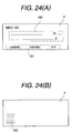
- Fig. 24 (A) Payment systems capable of handling personal checks are commonly used in supermarkets and other retailers. As shown in Fig. 24 (A), these checks have a payment information area 240 on the front of the check for writing the amount, payee (store name), and the check writer's signature, and magnetic ink character text 241 for recording a unique check verification number. An endorsement area 242 is further provided on the back of the check as shown in Fig. 24 (B) for endorsement by the payee.
- the check issuer or user handwrites the amount and store name, and signs the check in payment information area 240.
- MICR scanner at the checkout register then scans the magnetic ink character text 241 to obtain the bank and account number information, his information is then sent to the bank for check verification.
- a printer at the checkout register prints the store's endorsement information to the endorsement area 242 on the back of the check.
- the check is then sent via the store's bank to the customer's bank where an image of the check is captured to microfilm and stored for a period of time.
- a problem with this common process is that different devices are required for each step of the process and many of the steps are manually performed. he check must therefore be manually transferred between steps, and completing the transaction thus becomes time-consuming. While printers having an integral MICR reader are now also available, the operator must still turn the check over between MICR scanning and endorsement printing steps.
- the conventional transaction process requires the bank issuing the check to recover the physical check and record an image thereof to microfilm.
- the danger of the check becoming lost or stolen during the transfer from retailer to issuing bank is, therefore, the danger of the check becoming lost or stolen during the transfer from retailer to issuing bank.
- a printer has a transportation path for transporting a check or other print medium from a form insertion opening to an ejection opening; a form transport means for moving the print medium through the transportation path; an image reader for capturing an image of the print medium transported through the transportation path; a printing mechanism for printing to the print medium transported through the transportation path; a reverse feed mechanism disposed to the transportation path upstream of the ejection opening for reversing to the upstream side a print medium transported to the downstream side of the transportation path; and a return path for guiding a print medium reverse fed by the reverse feed mechanism to a position on the transportation path on the upstream side of the image reader is featured.
- the printer further has a path divider disposed at the junction between the downstream end of the transportation path and the return path.
- he path divider guides to the ejection opening a print medium advanced from the upstream side of the transportation path to the path junction, and guides to the return path a print medium reversed by the reverse feed mechanism from a downstream side of the transportation path to the path junction.
- the path divider is a path switch supported so that it can pivot on a shaft.
- he path switch is normally urged in a direction closing the transportation path at the path junction, and can be opened by the force of the leading edge of a print medium advanced toward the ejection opening and contacting the path switch.
- the form transport means comprises two drive side transport rollers disposed at mutually separated positions.
- a circulation path formed by the transportation path and return path is disposed around these two rollers.
- the printer additionally comprises a third transport roller driven in forward and reverse directions and disposed to the transportation path upstream of the ejection opening.
- he reverse feed mechanism in this case is achieved by driving the third transport roller in reverse.
- a printer further has a reversible motor; a first gear set for driving the third transport roller forward or reverse according to the direction of motor rotation; and a second gear set for driving the two transport rollers of the form transport means forward regardless of the direction of motor rotation.
- the second gear set comprises two one-way clutches supported on a rotating shaft of one transport roller to alternately transfer torque in the same direction of rotation to the transport roller, a third gear set for transferring drive force from the motor during forward motor drive to the transport roller by way of one intervening one-way clutch, and a fourth gear set for transferring drive force from the motor during reverse motor drive to the transport roller by way of the other intervening one-way clutch.
- the printing mechanism of this printer has a print head, and a print head transport mechanism for moving the print head substantially orthogonal to the print medium transport direction.
- the printer has a magnetic ink character reader for reading magnetic ink characters on the print .medium.
- the magnetic ink character reader is disposed to the transportation path downstream of the image reader.
- the magnetic ink character reader has a magnetic head; and a magnetic head transport mechanism for moving the magnetic head substantially orthogonal to the print medium transport direction.
- the magnetic head transport mechanism is achieved by the print head transport mechanism.
- the printer comprises a character recognition means for recognizing magnetic ink characters on the print medium as character information, the magnetic ink characters being detected in the image of the print medium captured by the image reader.
- the printer comprises a data capturing means for obtaining information relating to a print area of the print medium from the print medium image captured by the image reader. This captured data is then used to control the printing mechanism.
- the printer comprises a form length detector for detecting a length of a print medium guided through the transportation path, and a reverse feed controller for prohibiting reverse feed of the print medium by the reverse feed mechanism when the print medium length detected by the length detector is longer than a length of the form circulation path formed by the transportation path and return path.
- a control method for a printer having the printing mechanism thereof disposed downstream of an image reader disposed to a transportation path includes reading an image of a print medium, printing to a first side of the print medium, feeding the print medium to the return path by reversing the print medium transport direction, and printing to a second side of the print medium by the printing mechanism.
- control method further features feeding the print medium to the return path by reversing the print medium transport direction by the reverse feed mechanism, capturing an image of the print medium during form transportation, and ejecting the print medium from the ejection opening.
- a control method for a printer having the printing mechanism thereof disposed upstream of an image reader disposed to a transportation path includes a printing to a first side of the print medium by the printing mechanism, reading an image of the printed first side of the print medium, feeding the print medium to the return path by reversing the print medium transport direction by the reverse feed mechanism, printing to a second side of the print medium by the printing mechanism, reading an image of the printed second side of the print medium, and ejecting the print medium from the ejection opening.
- a control method for a printer having a form length detection means includes printing to a first side of the print medium by the printing mechanism, reading an image of the printed first side of the print medium, detecting by the length detection means a length of the print medium guided to the transportation path, and ejecting the print medium from the ejection opening when the print medium length detected by the length detector is longer than a length of the form circulation path formed by the transportation path and return path.
- An advantage of the above-described aspects and implementations is the enablement of a more efficient handling and completion of check transactions.
- Another advantage provided by implementations of the printer is that it can complete these check transactions without operator intervention.
- Yet another advantage provides a printer that is compact and suited for high speed check processing.
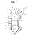
- Fig. 1 is a typical side view of the internal structure of a printer according to an embodiment.
- this printer comprises a transportation path 12 for transporting a check P inserted from insertion opening 10 to form ejection opening 11, and two drive rollers 13 and 14 disposed separated from each other.
- the transportation path 12 is a basically U-shaped path formed passing around the drive rollers 13 and 14.
- a check P supplied to the printer from insertion opening 10 is first pulled into the transportation path 12 by drive roller 13, then fed upwards by means of drive roller 14 and cooperating auxiliary rollers 15, and then once again advanced toward the ejection opening 11 by drive roller 13.
- the check P is assumed herein to be inserted to the insertion opening 10 and transported from the long side of the check P.
- a scanner 16, print head 17, and magnetic head 18 are disposed along the transportation path 12.
- the scanner 16 is disposed opposite the drive roller 13 at a position close to the insertion opening 10 of the transportation path 12.
- the scanner 16 captures an image of one side of the check P, and covers the width of the transportation path 12, that is, depthwise as seen in Fig. 1, so that it scans the full width of a check P as the check passes between the scanner 16 and drive roller 13.
- the scanner 16 captures an image of the check P front twice.
- the first image captured is used for analyzing the magnetic ink characters printed to the check P.
- the second captured image is transmitted to the bank upon which the check is drawn, and is used in place of conventional microfilm storage.
- the scanner 16 is also used as a form edge detector for sensing a check edge.
- the scanner 16 outputs the captured image data to an optical character reader (OCR) used as the character recognition means.
- OCR optical character reader
- the print head 17 and magnetic head 18 are downstream of the scanner 16. For convenience of illustration only the print head 17 and magnetic head 18 are shown side by side in the transportation direction of check P in Fig. 1, but they are actually side by side in the depth direction of Fig. 1, that is, across the width of the transportation path as shown in Fig. 2.
- the print head 17 prints the amount and store name to the payment information area 240 on the check P front, and the endorsement information to the endorsement area 242 on the back of the check P.
- the magnetic head 18 is for reading the magnetic ink character text 241 on the check P front, and is typically known as a magnetic ink character reader (MICR).
- MICR magnetic ink character reader
- the magnetic ink character data read by the magnetic head 18 is used when the scanner 16 was not able to read the magnetic ink characters with good results. It is also possible to leave character recognition solely to the scanner 16 and use the magnetic head 18 only for detecting the presence of magnetism in the ink.
- the print head 17 and magnetic head 18 are mounted on the same carriage and are moved by the same transportation mechanism across the transportation path 12. The print head 17 is driven in conjunction with this movement when printing to the check, and the magnetic head 18 is driven when reading the magnetic ink characters.
- a transport roller pair 19 is located near the ejection opening 11.
- the transport roller pair 19 is controlled to turn in forward or reverse direction.
- a check P in the transportation path 12 is carried toward to the ejection opening 11.
- a check P that has been advanced to the ejection opening 11 is fed back into form return path 20.
- This form return path 20 is a path linking a part of the transportation path 12 near the insertion opening 10 with a part of the path 12 near ejection opening 11.
- the substantially U-shaped transportation path 12 and this form return path 20 together form a circumferential path around drive rollers 13 and 14.
- Part of drive roller 13 projects into this form return path 20 so that rotation of the drive roller 13 carries a check P reversed into form return path 20 to a point on the upstream end of transportation path 12. This means that a check P reversed by transport roller pair 19 is inverted front and back and then fed back into transportation path 12.
- a path switch 21 for switching the form path between transportation path 12 and form return path 20 is provided upstream of transport roller pair 19 at the junction between transportation path 12 and form return path 20.
- This path switch 21 is normally held by a spring or other urging mechanisms not shown in the figure so that the path junction is closed to the upstream end of the transportation path 12 and the form return path 20 is open to the downstream end of the transportation path 12.
- the leading edge of the check P advanced from the upstream side of the transportation path 12 strikes the path switch 21 at the path junction.
- the form transportation force and the rigidity of the check P open the path switch 21 in resistance to the urging mechanism so that check P can be advanced to the ejection opening 11.
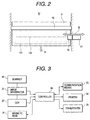
- Fig. 2 is a view from arrow A in Fig. 1 clearly showing the relative positions of the scanner 16, print head 17, and magnetic head 18 to the transportation path 12.
- the scanning width of the scanner 16 is approximately equal to the width of the check P.
- the print head 17 and magnetic head 18 are mounted on a common carriage, and travel in the direction of arrow B orthogonal to form transportation direction A.
- the carriage is driven so that the magnetic head 18 reads the magnetic ink characters.
- the payment information area 240 reaches the path passing print head 17, the carriage is again driven to print by the print head 17.
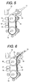
- Fig. 3 is a block diagram of a controller used with this printer.
- Printer control is achieved primarily by means of controller 30 using a CPU and a control program the controller 30 runs on the CPU.
- Check image data captured by the scanner 16 is analyzed by the image interpreter 31 to detect information, including the form edge position, print area, and magnetic ink character area. This information is sent to the controller 30.
- the magnetic ink character area is extracted and the characters are recognized (read) by the OCR 32.
- the magnetic ink characters are also read by the magnetic head 18.
- the magnetic ink character data is then transmitted by way of communication means 33 to a host computer at a bank or other financial institution for verification.
- the controller 30 also controls a printer 34, transporter 35, scanner 16, magnetic head 18, and other components in response to information captured from the check P or control commands from the operator.
- Fig. 4 shows the drive system for the drive rollers 13 and 14 and transport roller pair 19.
- drive rollers 13 and 14 and transport roller pair 19 are rotationally driven by drive power supplied from a single reversible motor 40 and transferred by gear set 41.
- This gear set 41 causes transport roller pair 19 to turn forward or reverse depending upon the direction of motor 40 rotation, and always drive drive rollers 13 and 14 forward regardless of the direction of motor 40 rotation.
- the drive power of motor 40 is transferred through gears 42, 43, 44, 45, 46, and 47 for driving transport roller pair 19.
- transport roller pair 19 is driven in the forward direction by driving motor 40 in the forward direction.
- Check P is thus carried toward the ejection opening 11.
- the motor 40 is reversed. This causes transport roller pair 19 to move in the reverse direction and thus reverses the check P to the form return path 20.
- the gear set 41 additionally uses gears 48, 49, 50, 51, 52, and 53, and two one-way clutches 54 and 55.
- Gears 51 and 53 are mounted on the respective drive shafts of drive rollers 13 and 14 and are linked by meshing with an intermediate gear 52.
- Drive power transferred to drive drive roller 13 in a forward direction is thus also transferred to the drive shaft gear 53 of drive roller 14, and thus causes drive roller 14 to be driven in the same forward direction.
- the two one-way clutches 54 and 55 are both disposed to the drive shaft 56 of the one drive roller 13, and transfer only the forward rotation of gears 48 and 50 to the drive roller 13. When these gears turn in the reverse direction, the clutches 54 and 55 disengage from drive shaft 56, and drive power is thus not transferred to the drive shaft 56.
- the motor 40 is driven forward, drive power is transferred from gear 42 to drive gear 48 forward.
- gear 48 turns forward, clutch 54 engages drive shaft 56, thus transferring the drive power to drive roller 13 and thereby driving drive roller 13 forward.
- Drive power from motor 40 is further transferred at this time by way of gears 42, 43, 44, 45, 46, and 49 to gear 50.
- Gear 50 at this time turns in reverse, but drive power is not transferred to drive shaft 56 by clutch 55, and gear 50 turns freely to drive shaft 56, which is driven in the forward direction at this time by the drive power transferred from gear 48.
- gears 42, 43, 44, 45, 46 and 49 When motor 40 turns in reverse, that is, when the transport roller pair 19 is driven in reverse, drive power is transferred by way of gears 42, 43, 44, 45, 46 and 49 to drive gear 50 forward.
- gear 50 turns forward
- clutch 55 engages drive shaft 56
- drive power is transferred to drive roller 13, and drive roller 13 thus turns forward.
- Drive power from the motor 40 is also transferred by way of gear 42 to gear 48 at this time.
- gear 48 turns in reverse but because clutch 54 disengages drive power is not transferred from gear 48 to drive shaft 56, and gear 48 turns freely to drive shaft 56, which is not driven forward by means of drive power transferred from gear 50.
- motor 40 drives forward or reverse, drive rollers 13 and 14 are always driven in the forward direction.
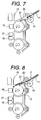
- FIG. 5 to Fig. 13 show various stages in the processing of a check P inserted to this printer.
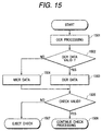
- Figs. 14 and 15 are flow charts of this check P processing routine.
- the checkout clerk When a customer uses a check to pay for a store purchase, the checkout clerk (operator) first has the customer sign the check in the specified space before the check is processed by the printer. Upon receiving the signed blank check from the customer, the operator inserts the check P to the insertion opening 10 with the front of the check facing the side of the transportation path 12 on which the scanner 16 is disposed.
- a check P inserted to the printer is advanced by drive rollers 13 and 14 through transportation path 12 toward the ejection opening 11 as shown in Fig. 5.
- an image of the check front is first captured by scanner 16 (step 1401 in Fig. 14).
- the magnetic ink characters are then scanned and read by the magnetic head 18 as area 241 passes thereby (1402).
- the payment information area 240 reaches print head 17, the check amount and store name (payee) are printed (1403).
- the check P When processing the check front is completed, the check P is advanced to the ejection opening 11 as shown in Fig. 6. The leading edge of the check P opens the path switch 21 at the junction with form return path 20, and the check P is thus fed to the transport roller pair 19. The check P is then advanced to the ejection opening 11 by transport roller pair 19 until the trailing edge of the check passes the path junction as shown in Fig. 7. This allows path switch 21 to return to its previous normal position, thus opening form return path 20.
- Rotation of the transport roller pair 19 is reversed once the path switch 21 returns so that the check P returns through form return path 20 to a position on the upstream side of the transportation path 12 (1404). This operation inverts check P so that it is passed again through transportation path 12 but with the opposite (endorsement) side presented to the print head 17.
- the check P verification process shown in Fig. 15 is accomplished either before or parallel to this form inverting process.
- the first step in this verification process is to recognize the magnetic ink characters from the image data captured by the scanner 16 (1501).
- Next is to detect whether character recognition based on the image data was appropriately accomplished (1502). If it was, the character data recognized from the image data is checked with the bank (1503). However, if the text was not correctly read due, for example, to soiling of the magnetic ink character area, the character data read by the magnetic head 18 is used for verification with the bank (1504). If the check is determined valid after waiting for the bank's response (1505), control returns to the procedure shown in Fig. 14 to finish check processing (1506). However, if the check is not confirmed by the bank to be valid, processing terminates and the check P is ejected from ejection opening 11 (1507).
- the check P is transported as shown in Fig. 9 so that the endorsement area 242 is presented to the print head 17. This time the print head 17 prints the check endorsement information (1405).
- the check P is advanced to the ejection opening 11 as shown in Fig. 10.
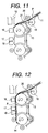
- the check P is again reversed by the transport roller pair 19 and returned to the upstream side of transportation path 12 as shown in Fig. 11 (1406).
- the check P is thus again inverted so that it passes once more through transportation path 12, this time with the front facing scanner 16.
- the scanner 16 is then again driven as the check passes by to capture an image of the completed signed check P (1407). This time the check is scanned the face of the check is completely filled out, containing the customer's signature, check amount, payee, and magnetic ink character account information.
- the resulting image is then sent to the bank where it is stored.
- the scanner 16 is disposed lengthwise to the check P, it is also possible to capture an image of only those parts of the check from which an image needs to be archived, such as the customer signature, amount, and payee.
- the size of the captured image, and thus the amount of data to be stored, can thereby be reduced and the processing time shortened.
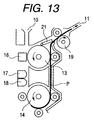
- the check P is advanced through transportation path 12 and ejected from the ejection opening 11 as shown in Fig. 13 (1408). This completes the check P processing routine.
- the front of the check P is scanned twice 1401, 1407 in Fig. 14.
- the primary purpose of scanning 1401, however, is to supplement reading the magnetic ink characters with an OCR function, and the object of step 1407 is to capture and store an image of the completed check.
- Other capture methods are possible. For example, it is also possible to capture 1401 an image of only that part of the check not printed 1403, capture 1407 an image of only that part printed 1403, and then combine these two scanned images to generate an image of the entire front side of the check P. This makes it possible to process the scanned image data in separate batches using, for example, the check P transportation time, and thereby improve process throughput.
- check P insertion direction that is, whether the front or back was inserted facing the scanner 16, for example, using the image data captured 1401. This can be accomplished by generating standard patterns from scanned check images, calculating a correlation between these standard check patterns and the image captured from the inserted check, and using this correlation to detect the insertion direction.
- check inversion 1404 can be accomplished before MICR reading 1402 if the check P was inserted backwards so that the subsequent check processing routine can be performed smoothly.
- the position at which the check P is stopped in MICR reading 1402 can be adjusted so that the magnetic head 18 reliably scans the MICR text. Accurate recognition can also be assured in this case by rotating the sample data used for the MICR operation 180 degrees. The print data can also be rotated 180 degrees in printing steps 1403, 1405 to assure the data is correctly printed.
- Fig. 16 is a typical side view showing the internal structure of a printer according to this embodiment
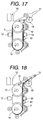
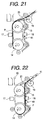
- Figs. 17 to 22 show the show various stages in the processing of a check P inserted to this printer
- Fig. 23 is a flow chart of the check P processing routine.
- Like parts in a printer according to this embodiment and the embodiment described above are identified by like reference numeral, and further description thereof is omitted below.
- the control system shown in Fig. 3 and the drive control system as shown in Fig. 4 are also used in this exemplary printer, and further description thereof is also omitted below.
- the printer 60 comprises a scanner 16 identical to that in the preceding embodiment. What differs is that this scanner 16 is disposed downstream of the print head 17, that is, on the opposite side of the U-shaped transportation path 12 from print head 17. As described below with reference to control of this printer 60, scanner 16 scans the check P after it has been printed by the print head 17, thus shortening the check P processing time and improving throughput.
- a printer 60 according to this embodiment does not have a magnetic head, and scanner 16 alone is used for recognizing the magnetic ink characters.
- This printer 60 further includes a form edge sensor 61 disposed to the transportation path 12 on the upstream side of scanner 16.
- This form edge sensor 61 detects the leading and trailing edges of a form passing through transportation path 12.
- the printer 60 controller measures the length of the form being processed based on the output from form edge sensor 61. In other words, the number of feed steps advanced by the drive rollers 13 and 14 between when the form edge sensor 61 detects the leading and trailing edges of the form is counted. This count is then used to calculate the form length.
- Form length detection is used to control form reversal by the transport roller pair 19. If the form inserted from insertion opening 10 is not check P and the length of the inserted form in the form advancing direction is greater than the length of the circulation path (the circulation path length below) formed by transportation path 12 and form return path 20, a paper jam can be caused at the path junction by feeding the form in reverse. That is, if a form longer than the circulation path length is advanced to the transportation path 12 by reverse rotation of the transport roller pair 19, the leading edge of the form will reach the path junction before the trailing edge thereof passes back through the path junction. This means that the leading edge pushes the path switch 21 up and thereby closes the form return path 20, possibly resulting in the trailing edge of the form being pinched. To prevent this, a printer 60 according to this embodiment of the invention is controlled to simply eject and not reverse any inserted form that is longer than the circulation path length.
- the checkout clerk When a customer uses a check to pay for a store purchase, the checkout clerk (operator) first has the customer sign the check in the specified space before the check is processed by the printer. Upon receiving the signed blank check from the customer, the operator inserts the check P to the insertion opening 10 with the front of the check facing the side of the transportation path 12 on which the print head 17 is disposed.
- a check P inserted to the printer is advanced by drive rollers 13 and 14 through transportation path 12 toward the ejection opening 11 as shown in Fig. 17.
- the payment information area 240 reaches print head 17, the check amount and store name (payee) are printed (2301).
- the leading edge of check P reaches the path junction with form return path 20 while the scanner 16 is capturing an image of the check face.
- the leading edge thus pushes the path switch 21 at the junction to form return path 20 open, and the check P is guided to transport roller pair 19.
- the transport roller pair 19 advances the check P to ejection opening 11.
- the path switch 21 returns to the previous position and opens form return path 20.
- the length of check P is measured and whether the results of magnetic ink character recognition are appropriate is determined before the check P is reversed from the position shown in Fig. 19 (2303). If character recognition was correct, the next step 2304 is performed while at the same time the character data is transmitted to the bank for verification as in the preceding embodiment.
- step 2309 and 2310 can be performed when check P validity is not verified by the bank. Furthermore, if it is detected in step 2303 that character recognition was not appropriately completed, further processing can be immediately terminated with the procedure skipping directly to step 2308 and the check P being immediately ejected.
- step 2303 detects that character recognition was appropriately completed, the check P length is next calculated and compared with the circulation path length.
- the form edge sensor 61 detects when the trailing edge of check P passes thereby as it is advanced to ejection opening 11 as shown in Fig. 18. A signal is then sent to the controller to stop counting drive roller 13 steps. Based on the number of steps counted by the controller and the distance advanced by drive roller 13 with each step, the controller can calculate the length of check P.
- the calculated check P length is then compared with the circulation path length (2304). If the check P length is greater than the circulation path length, a paper jam could result by reversing the form through form return path 20. Processing is therefore terminated by continuing to drive the transport roller pair 19 forward and eject the check P from ejection opening 11 (2308).
- the check P length is less than the circulation path length, the check P is determined to be an appropriate length and check processing continues. That is, the transport roller pair 19 is reversed so that the check P returns from form return path 20 to a position upstream of the transportation path 12 as shown in Fig. 20 (2305).
- This operation inverts the side of check P so that it is passed again through transportation path 12 with the opposite (endorsement) side presented to the print head 17.
- the print head 17 prints the check endorsement information (2306).
- the check P is advanced to the ejection opening 11 as shown in Fig. 22, during which time an image of the check back is captured by the scanner 16 and stored (2307). After the image is captured the check P is advanced through transportation path 12 and ejected from the ejection opening 11 to outside the printer (2308). This completes check P processing.
- Check processing by this embodiment circulates the check P only once through the printer. Processing time is thus shortened and throughput improved.
- Print head 17 and magnetic head 18 are mounted on a common carriage and moved together in the described embodiments. These can be mounted on separate carriages and moved independently.
- the print head 17 is also used to print the check amount and payee, but can alternatively be used to print only the endorsement information.
- the scanner 16, print head 17 and magnetic head 18 are disposed toward the insertion opening 10 in the above embodiments, but they can be provided further downstream or on the opposite side of the transportation path 12.
- a series of processes on the front and back sides of a check or other print medium can be efficiently accomplished by means of the present invention without requiring operator intervention to reverse the print medium.
- a printer capable of performing this process can be achieved in an extremely compact configuration.
Landscapes
- Engineering & Computer Science (AREA)
- Multimedia (AREA)
- Signal Processing (AREA)
- Financial Or Insurance-Related Operations Such As Payment And Settlement (AREA)
- Printers Characterized By Their Purpose (AREA)
- Handling Of Cut Paper (AREA)
Abstract
Description
- P
- check
- 10
- insertion opening
- 11
- ejection opening
- 12
- transportation path
- 13, 14
- drive rollers
- 15
- auxiliary rollers
- 16
- scanner
- 17
- print head
- 18
- magnetic head
- 19
- transport roller pair
- 20
- form return path
- 21
- path switch
- 30
- controller
- 31
- image interpreter
- 33
- communication means
- 34
- printing means
- 35
- transportation means
Claims (24)
- A printer, comprising:a transportation path having a print medium insertion opening and an ejection opening;a print medium transporter coupled to the transportation path, the print medium transporter adapted to move a print medium through the transportation path between the insertion opening and the ejection opening;an image reader disposed adjacent the transportation path and oriented to capture an image of the print medium;a printing mechanism disposed adjacent the transportation path and oriented to print on the printing medium;a reverse feed mechanism disposed to the transportation path upstream of the ejection opening and adapted to reverse feed the print medium; anda return path connected to the reverse feed mechanism and to a portion of the transportation path upstream of the image reader.
- A printer as described in claim 1, wherein the printing mechanism is disposed to the transportation path downstream of the image reader.
- A printer as described in claim 1, wherein the printing mechanism is disposed to the transportation path upstream of the image reader.
- A printer as described in claim 1, further comprising a path divider at a junction between the transportation path and return path, the path divider adapted to guide to the ejection opening a print medium advanced from the upstream side of the transportation path to the path junction, and adapted to guide to the return path a print medium reversed by the reverse feed mechanism from a downstream side of the transportation path to the path junction.
- A printer as described in claim 4, wherein the path divider is a path switch rotatably shaft supported, oriented in a direction closing the transportation path at the path junction, and adapted to be opened by a force of a leading edge of a print medium advanced toward the ejection opening and contacting the path switch.
- A printer as described in claim 1, wherein the print medium transporter comprises two drive side transport rollers disposed mutually separated, and a circulation path formed by the transportation path, the return path being disposed around the rollers.
- A printer as described in claim 6, further comprising a third transport roller driven in forward and reverse directions and disposed to the transportation path upstream of the ejection opening, wherein the reverse feed mechanism is achieved by driving the third transport roller in reverse.
- A printer as described in claim 7, further comprising a reversible motor;a first gear set adapted to drive the third transport roller forward or reverse according to the direction of motor rotation; anda second gear set adapted to drive the two transport rollers of the print medium transporter forward regardless of the direction of motor rotation.
- A printer as described in claim 8, wherein the second gear set comprises:motor drive to the transport roller by way of the other intervening one-way clutch.two one-way clutches supported on a rotating shaft of one transport roller of the print medium transporter adapted to alternately transfer torque in the same direction of rotation to said transport roller;a third gear set adapted to transfer drive force from the motor during forward motor drive to the transport roller by way of one intervening one-way clutch; anda fourth gear set adapted to transfer drive force from the motor during reverse motor drive to the transport roller by way of the other intervening one-way clutch.
- A printer as described in claim 1, in which the printing mechanism comprises:a print head; anda print head transport mechanism for moving the print head substantially orthogonal to the print medium transport direction.
- A printer as described in claim 1, further comprising a magnetic ink character reader disposed to the transportation path on a downstream side of the image reader.
- A printer as described in claim 11, wherein the magnetic ink character reader comprises:a magnetic head; anda magnetic head transport mechanism for moving the magnetic head substantially orthogonal to the print medium transport direction.
- A printer as described in claim 12, wherein the magnetic head transport mechanism is achieved by the print head transport mechanism.
- A printer as described in claim 1, further comprising a character recognition mechanism adapted to detect magnetic ink characters on the print medium captured and stored by the image reader.
- A printer as described in claim 1, further comprising a data capture mechanism adapted to obtain information relating to a print area of the print medium from the print medium image captured by the image reader, wherein the printing mechanism is controlled based on the captured data.
- A printer as described in claim 1, further comprising a print medium length detector adjacent the transportation path; anda reverse feed controller adapted to prohibit reverse feed of the print medium by the reverse feed mechanism when the print medium length detected by the length detector is longer than a length of a circulation path formed by the transportation path and return path.
- A printer as described in claim 1, wherein the print medium is a check.
- A printer control method, comprising:reading an image of a print medium transported through a print medium transporter;printing to a first side of the print medium by a printing mechanism;feeding the print medium to a return path by reversing the print medium transport direction by a reverse feed mechanism; andprinting to a second side of the print medium by a printing mechanism.
- A control method as described in claim 18, further comprising:feeding the print medium to the return path by reversing the print medium transport direction by the reverse feed mechanism;an capturing an image of the print medium during the print medium transportation by an image reader; andejecting the print medium from an ejection opening.
- A printer control method comprising:printing to a first side of a print medium by a printing mechanism;reading an image of a printed first side of the print medium;feeding the print medium to a return path by reversing the print medium transport direction by a reverse feed mechanism;printing to a second side of the print medium by the printing mechanism;reading an image of the printed second side of the print medium; andejecting the print medium from the ejection opening.
- A printer control method comprising:printing to a first side of a print medium by a printing mechanism;reading an image of a printed first side of the print medium;detecting by a length detector a length of the print medium guided to the transportation path; andejecting the print medium from an ejection opening when the print medium length detected by the length detector is longer than a length of a circulation path formed by the transportation path and return path.
- A printer comprising:a transportation path for transporting a print medium from an insertion opening to an ejection opening;transporting means for moving a print medium in the transportation path;image reading means disposed to the transportation path for capturing an image of a print medium transported in the transportation path;printing means disposed to the transportation path for printing to the print medium being transported through the transportation path;reverse feeding means disposed to the transportation path upstream of the ejection opening for reversing to the upstream side a print medium transported to the downstream side of the transportation path; anda return path for guiding a print medium reverse fed by the reverse feed mechanism to a position on the transportation path on the upstream side of the image reader.
- A printer comprising:a U-shaped transportation path having an insertion opening on one end and an ejection opening on an other end;a first roller disposed inside the U-shape at an intermediate part of the transportation path;a second roller disposed inside the U-shape near the insertion opening to the transportation path; anda third roller disposed near the ejection opening for pulling the print medium out from the transportation path and then passing the print medium above the first roller for printing to or scanning a reverse side of a first side of the print medium after printing to or scanning the first side of a print medium transported in the transportation path.
- A printer device as described in claim 23, in which the first roller and second roller always turn in a same direction, andthe third roller turns in forward and reverse directions.
Applications Claiming Priority (2)
| Application Number | Priority Date | Filing Date | Title |
|---|---|---|---|
| JP9002299 | 1999-03-30 | ||
| JP9002299 | 1999-03-30 |
Publications (2)
| Publication Number | Publication Date |
|---|---|
| EP1041806A2 true EP1041806A2 (en) | 2000-10-04 |
| EP1041806A3 EP1041806A3 (en) | 2001-09-19 |
Family
ID=13987080
Family Applications (1)
| Application Number | Title | Priority Date | Filing Date |
|---|---|---|---|
| EP00106066A Withdrawn EP1041806A3 (en) | 1999-03-30 | 2000-03-29 | Printer and control method for the same |
Country Status (4)
| Country | Link |
|---|---|
| US (1) | US6257783B1 (en) |
| EP (1) | EP1041806A3 (en) |
| KR (1) | KR100776922B1 (en) |
| CN (1) | CN1170689C (en) |
Cited By (5)
| Publication number | Priority date | Publication date | Assignee | Title |
|---|---|---|---|---|
| US6695427B2 (en) | 1997-08-06 | 2004-02-24 | Seiko Epson Corporation | Multifunction device and control method for the same |
| US6832723B2 (en) | 2001-06-22 | 2004-12-21 | Seiko Epson Corporation | Scanner apparatus and multifunction device having a scanner |
| US6983885B2 (en) * | 2001-06-22 | 2006-01-10 | Seiko Epson Corporation | Print media processing apparatus and control method for the same |
| EP2141103A1 (en) * | 2008-07-01 | 2010-01-06 | Sagem Communications Sas | Device for treating sheets equipped with means for preventing jamming when reinserting a sheet |
| WO2018077927A1 (en) * | 2016-10-27 | 2018-05-03 | Bundesdruckerei Gmbh | Device and method for printing onto a curved substrate |
Families Citing this family (55)
| Publication number | Priority date | Publication date | Assignee | Title |
|---|---|---|---|---|
| US6704553B1 (en) * | 1997-10-08 | 2004-03-09 | Thomas M. Eubanks | System and method for providing automatic tuning of a radio receiver and for providing automatic control of a CD/tape player |
| US7386511B2 (en) * | 2000-04-28 | 2008-06-10 | Netdeposit Inc. | Methods and systems for processing financial instrument deposits |
| US7216106B1 (en) * | 2000-04-28 | 2007-05-08 | Netdeposit, Inc. | Method and system for processing financial instrument deposits physically remote from a financial institution |
| US7181430B1 (en) * | 2000-04-28 | 2007-02-20 | Netdeposit, Inc. | Method and system for processing financial instrument deposits physically remote from a financial institution |
| US7475040B2 (en) * | 2000-04-28 | 2009-01-06 | Netdeposit, Inc. | Return item early notification and return |
| CN1215940C (en) * | 2001-06-04 | 2005-08-24 | 精工爱普生株式会社 | Printer with page turning mechanism |
| US20040044606A1 (en) * | 2001-08-09 | 2004-03-04 | Buttridge Kelly A. | Methods and systems for check processing |
| US20030033252A1 (en) * | 2001-08-09 | 2003-02-13 | Buttridge Kelly A. | Methods and systems for check processing using blank checks at a point-of-sale |
| US20030126081A1 (en) * | 2001-11-16 | 2003-07-03 | Hiroshi Ono | Check processing method and apparatus, and a computer-readable recording medium storing a check processing control program |
| CA2381375A1 (en) * | 2002-04-10 | 2003-10-10 | Rdm Corporation | Document processing machine |
| CA2435621C (en) * | 2002-07-22 | 2013-04-09 | Netdeposit, Inc. | Methods and systems for processing financial instrument deposits |
| JP3938027B2 (en) * | 2002-12-02 | 2007-06-27 | キヤノン株式会社 | Image recording / reading apparatus and prescan method |
| JP4321230B2 (en) * | 2003-01-21 | 2009-08-26 | セイコーエプソン株式会社 | Data reader |
| SG122813A1 (en) * | 2003-01-24 | 2006-06-29 | Seiko Epson Corp | Printing apparatus and printing method |
| US7665655B2 (en) * | 2003-04-10 | 2010-02-23 | Rdm Corporation | Apparatus and method for presenting both faces of a document for processing |
| JP4183244B2 (en) * | 2003-04-18 | 2008-11-19 | キヤノン株式会社 | Recording device |
| US20050052672A1 (en) * | 2003-06-30 | 2005-03-10 | Srikrishna Talluri | Method and system to seamlessly capture and integrate text and image information |
| JP4251029B2 (en) * | 2003-07-28 | 2009-04-08 | セイコーエプソン株式会社 | Printing apparatus and control method thereof |
| JP4131206B2 (en) * | 2003-07-29 | 2008-08-13 | セイコーエプソン株式会社 | Medium reading apparatus and medium reading method |
| JP4389550B2 (en) * | 2003-10-31 | 2009-12-24 | セイコーエプソン株式会社 | Double feed detection device and composite processing device |
| US7210630B2 (en) | 2003-11-10 | 2007-05-01 | Seiko Epson Corporation | Image scanning apparatus and a hybrid processing apparatus incorporating the image scanning apparatus |
| JP4419527B2 (en) * | 2003-11-13 | 2010-02-24 | セイコーエプソン株式会社 | Host computer for check processing apparatus, check processing system, and check processing method |
| KR100610946B1 (en) | 2003-11-14 | 2006-08-09 | 세이코 엡슨 가부시키가이샤 | Paper storage apparatus, and a paper processing apparatus having a paper storage apparatus |
| KR100636464B1 (en) * | 2003-11-14 | 2006-10-18 | 세이코 엡슨 가부시키가이샤 | Information processing apparatus and transportation path opening/closing mechanism |
| US7090131B2 (en) * | 2004-02-16 | 2006-08-15 | Seiko Epson Corporation | Single-pass magnetic reading and optical reading apparatus and method |
| US6966714B2 (en) * | 2004-02-20 | 2005-11-22 | International Business Machines Corporation | Duplex check printer having a separately driven document inverting loop |
| JP4431961B2 (en) | 2004-03-05 | 2010-03-17 | ブラザー工業株式会社 | Image recording device |
| JP4691900B2 (en) | 2004-05-12 | 2011-06-01 | セイコーエプソン株式会社 | CHECK PROCESSING METHOD, PROGRAM, AND CHECK PROCESSING DEVICE |
| KR100600859B1 (en) * | 2004-05-20 | 2006-07-14 | (주)브레인유니온시스템 | Transfer device for liquid material applicator |
| JP2006054578A (en) | 2004-08-10 | 2006-02-23 | Brother Ind Ltd | Information processing apparatus and program |
| JP2006126956A (en) * | 2004-10-26 | 2006-05-18 | Seiko Epson Corp | Character recognition apparatus and method |
| JP4720161B2 (en) * | 2004-12-01 | 2011-07-13 | セイコーエプソン株式会社 | Composite processing apparatus and control method thereof |
| JP2007283553A (en) * | 2006-04-13 | 2007-11-01 | Seiko Epson Corp | Control method for print medium processing apparatus and print medium processing apparatus |
| JP2007283593A (en) * | 2006-04-14 | 2007-11-01 | Seiko Epson Corp | Print medium processing apparatus and conveyance control method thereof |
| US7735950B2 (en) * | 2006-08-28 | 2010-06-15 | Seiko Epson Corporation | Printing apparatus and printing medium conveying apparatus |
| US7837096B2 (en) * | 2006-11-10 | 2010-11-23 | Diebold Self-Service Systems | Banking machine apparatus controlled responsive to data bearing records |
| US7832631B2 (en) * | 2006-11-10 | 2010-11-16 | Diebold Self-Service Systems Division Of Diebold, Incorporated | Method of reading coded records including magnetic indicia on checks deposited in an automated banking machine |
| CN101964127B (en) * | 2006-11-10 | 2013-11-06 | 迪布尔特有限公司 | Method for sensing coded records and method of sensing magnetic marks on coded records |
| WO2008078125A1 (en) | 2006-12-22 | 2008-07-03 | Telecom Italia S.P.A. | Scanner and printer unit for payment instruments |
| JP5216430B2 (en) * | 2008-06-16 | 2013-06-19 | 理想科学工業株式会社 | Printing device |
| US20100014743A1 (en) * | 2008-07-21 | 2010-01-21 | James Michael Spall | Compact multipass document processor |
| US8359192B2 (en) * | 2008-11-19 | 2013-01-22 | Lemi Technology, Llc | System and method for internet radio station program discovery |
| US8141692B2 (en) * | 2008-12-31 | 2012-03-27 | Burroughs Payment Systems, Inc. | Check-processing device with single image camera |
| US8294919B2 (en) * | 2008-12-31 | 2012-10-23 | Burroughs Payment Systems, Inc. | Endorsement printing by building characters |
| US8307971B2 (en) * | 2008-12-31 | 2012-11-13 | Burroughs Payment Systems, Inc. | Check-processing device with conditionally-reversible track direction |
| US20100295232A1 (en) * | 2009-05-22 | 2010-11-25 | Spall J Michael | Document processing device with optimised reversing track layout and single image capacity |
| CN102029805B (en) * | 2009-09-24 | 2013-11-27 | 山东新北洋信息技术股份有限公司 | Recording medium processing apparatus and method with embedded information |
| DE102011000785A1 (en) | 2011-02-17 | 2012-08-23 | Wincor Nixdorf International Gmbh | Device for debiting checks |
| JP2012206497A (en) | 2011-03-15 | 2012-10-25 | Seiko Epson Corp | Multifunction printing device |
| EP2804760B1 (en) * | 2012-02-23 | 2020-09-09 | Entrust Datacard Corporation | Card reorienting mechanism and methods utilizing same |
| CN105235398B (en) * | 2014-07-07 | 2017-10-20 | 北大方正集团有限公司 | The Method of printing and device of adaptive Print direction |
| JP2016097548A (en) * | 2014-11-20 | 2016-05-30 | 株式会社沖データ | Printing device |
| JP6980506B2 (en) | 2017-12-08 | 2021-12-15 | 東芝テック株式会社 | Magnetic ink reader and printer |
| JP7551346B2 (en) * | 2020-06-16 | 2024-09-17 | 東芝テック株式会社 | Magnetic ink reader and printer |
| CN115447277B (en) * | 2021-05-20 | 2025-02-14 | 深圳市汉森软件股份有限公司 | Automatically detect Onepass printing devices and Onepass printing methods |
Family Cites Families (12)
| Publication number | Priority date | Publication date | Assignee | Title |
|---|---|---|---|---|
| US4944505A (en) * | 1989-01-30 | 1990-07-31 | Brandt, Inc. | Sheet length detector with skew compensation |
| JPH05170372A (en) | 1991-12-20 | 1993-07-09 | Fujitsu Ltd | Sheet reversing mechanism and double-sided printing apparatus using the same |
| JPH06171158A (en) | 1992-12-10 | 1994-06-21 | Tokyo Electric Co Ltd | Printer |
| US5415391A (en) * | 1994-05-31 | 1995-05-16 | Xerox Corporation | Low cost compact inverter |
| US5532839A (en) * | 1994-10-07 | 1996-07-02 | Xerox Corporation | Simplified document handler job recovery system with reduced memory duplicate scanned image detection |
| TW293899B (en) * | 1994-10-18 | 1996-12-21 | Seiko Epson Corp | |
| JPH08175766A (en) | 1994-12-22 | 1996-07-09 | Nec Corp | Printer |
| US5863074A (en) * | 1996-12-23 | 1999-01-26 | Wilkinson; Rudolph P. | Fraud inhibiting personal check and method |
| US5865547A (en) | 1997-01-10 | 1999-02-02 | International Business Machines Corporation | Check flipper for point of sale printer and method therefor |
| JPH10315550A (en) * | 1997-05-22 | 1998-12-02 | Seiko Epson Corp | Printer and control method thereof |
| US6103985A (en) * | 1997-08-04 | 2000-08-15 | Unisys Corporation | Turn around loop apparatus for document scanning/processing |
| JP3215811B2 (en) * | 1997-11-21 | 2001-10-09 | 京セラミタ株式会社 | Document reading device |
-
2000
- 2000-03-29 KR KR1020000016087A patent/KR100776922B1/en not_active Expired - Fee Related
- 2000-03-29 EP EP00106066A patent/EP1041806A3/en not_active Withdrawn
- 2000-03-30 CN CNB001083228A patent/CN1170689C/en not_active Expired - Fee Related
- 2000-03-30 US US09/538,753 patent/US6257783B1/en not_active Expired - Lifetime
Cited By (6)
| Publication number | Priority date | Publication date | Assignee | Title |
|---|---|---|---|---|
| US6695427B2 (en) | 1997-08-06 | 2004-02-24 | Seiko Epson Corporation | Multifunction device and control method for the same |
| US6832723B2 (en) | 2001-06-22 | 2004-12-21 | Seiko Epson Corporation | Scanner apparatus and multifunction device having a scanner |
| US6983885B2 (en) * | 2001-06-22 | 2006-01-10 | Seiko Epson Corporation | Print media processing apparatus and control method for the same |
| EP2141103A1 (en) * | 2008-07-01 | 2010-01-06 | Sagem Communications Sas | Device for treating sheets equipped with means for preventing jamming when reinserting a sheet |
| FR2933387A1 (en) * | 2008-07-01 | 2010-01-08 | Sagem Comm | SHEET PROCESSING DEVICE PROVIDED WITH MEANS AVOIDING JAMS WHEN REINFORCING A SHEET |
| WO2018077927A1 (en) * | 2016-10-27 | 2018-05-03 | Bundesdruckerei Gmbh | Device and method for printing onto a curved substrate |
Also Published As
| Publication number | Publication date |
|---|---|
| US6257783B1 (en) | 2001-07-10 |
| KR100776922B1 (en) | 2007-11-20 |
| EP1041806A3 (en) | 2001-09-19 |
| CN1170689C (en) | 2004-10-13 |
| CN1268436A (en) | 2000-10-04 |
| KR20000071501A (en) | 2000-11-25 |
Similar Documents
| Publication | Publication Date | Title |
|---|---|---|
| US6257783B1 (en) | Printer and control method for the same | |
| US7997478B2 (en) | Check processing method, check processing program medium, and check processing apparatus | |
| US7341178B2 (en) | Processing apparatus, system and method for processing checks in communication with a host computer and a host computer for controlling the check processing apparatus | |
| KR100392971B1 (en) | Complex processing unit and its control method | |
| JP2000344428A (en) | Printing apparatus and control method thereof | |
| US8457383B2 (en) | Recording device and control method for a recording device | |
| US6109521A (en) | Check processing method and apparatus | |
| US8382102B2 (en) | Transportation alignment device, control method for a transportation alignment device, and recording device | |
| EP0801356B1 (en) | Method and apparatus for reading magnetic ink characters | |
| CA2291901C (en) | Printing apparatus, method of controlling it and storage medium | |
| JP3716876B2 (en) | Magnetic pattern recognition method, magnetic pattern recognition apparatus, and combined processing apparatus | |
| US8098391B2 (en) | Document processing system having improved operational sequencing | |
| US6293715B1 (en) | Self contained point of sale printing system and method | |
| JP4797287B2 (en) | Composite processing apparatus and control method thereof | |
| US20100295232A1 (en) | Document processing device with optimised reversing track layout and single image capacity | |
| JP7551346B2 (en) | Magnetic ink reader and printer | |
| JP2002361957A (en) | Printer equipped with magnetic reader and printing method of check paper | |
| US8335368B2 (en) | Bi-directional dual-speed document processor | |
| CN107234882A (en) | The control method of authentication device, printing equipment and authentication device | |
| JPH0877271A (en) | Automatic transaction equipment | |
| HK1030907A (en) | Printing device and control method thereof | |
| JPH05342418A (en) | Card processor | |
| JPH05258095A (en) | Optical card read / write method and read / write device | |
| JPH07246743A (en) | Passbook handling device | |
| HK1014250B (en) | Printing apparatus and a control method therefor |
Legal Events
| Date | Code | Title | Description |
|---|---|---|---|
| PUAI | Public reference made under article 153(3) epc to a published international application that has entered the european phase |
Free format text: ORIGINAL CODE: 0009012 |
|
| AK | Designated contracting states |
Kind code of ref document: A2 Designated state(s): AT BE CH CY DE DK ES FI FR GB GR IE IT LI LU MC NL PT SE |
|
| AX | Request for extension of the european patent |
Free format text: AL;LT;LV;MK;RO;SI |
|
| PUAL | Search report despatched |
Free format text: ORIGINAL CODE: 0009013 |
|
| AK | Designated contracting states |
Kind code of ref document: A3 Designated state(s): AT BE CH CY DE DK ES FI FR GB GR IE IT LI LU MC NL PT SE |
|
| AX | Request for extension of the european patent |
Free format text: AL;LT;LV;MK;RO;SI |
|
| 17P | Request for examination filed |
Effective date: 20020124 |
|
| AKX | Designation fees paid |
Free format text: AT BE CH CY DE DK ES FI FR GB GR IE IT LI LU MC NL PT SE |
|
| 17Q | First examination report despatched |
Effective date: 20070928 |
|
| STAA | Information on the status of an ep patent application or granted ep patent |
Free format text: STATUS: THE APPLICATION IS DEEMED TO BE WITHDRAWN |
|
| 18D | Application deemed to be withdrawn |
Effective date: 20080409 |