EP1041726A2 - A receiving apparatus of spectrum spread communication system - Google Patents
A receiving apparatus of spectrum spread communication system Download PDFInfo
- Publication number
- EP1041726A2 EP1041726A2 EP00106641A EP00106641A EP1041726A2 EP 1041726 A2 EP1041726 A2 EP 1041726A2 EP 00106641 A EP00106641 A EP 00106641A EP 00106641 A EP00106641 A EP 00106641A EP 1041726 A2 EP1041726 A2 EP 1041726A2
- Authority
- EP
- European Patent Office
- Prior art keywords
- signals
- detection
- outputs
- receiving apparatus
- series
- Prior art date
- Legal status (The legal status is an assumption and is not a legal conclusion. Google has not performed a legal analysis and makes no representation as to the accuracy of the status listed.)
- Granted
Links
Images


Classifications
-
- H—ELECTRICITY
- H04—ELECTRIC COMMUNICATION TECHNIQUE
- H04B—TRANSMISSION
- H04B1/00—Details of transmission systems, not covered by a single one of groups H04B3/00 - H04B13/00; Details of transmission systems not characterised by the medium used for transmission
- H04B1/69—Spread spectrum techniques
- H04B1/707—Spread spectrum techniques using direct sequence modulation
Definitions
- the present invention relates to a receiving apparatus of spectrum spread communication system used in a code division multiple access system (CDMA). Description of the Related Art
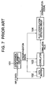
- FIG. 7 is a block diagram showing a conventional receiving apparatus of spectrum spread communication system.
- the receiving apparatus of spectrum spread communication system shown in FIG. 7 comprises a synchronism establishing circuit 101, a data buffer 102, a correlator 103 for de-spreading reception data using a transmission spread code based on a synchronization signal and a pilot interpolation detection circuit 104 for detecting a correlator output.
- the object of the present invention is to provide a receiving apparatus of spectrum spread communication system realizing optimum detection characteristics irrespectively of fading pitches when a signal is received in fading environment.
- a receiving apparatus of spectrum spread communication system comprises a plurality of detection circuits, each has optimum detection characteristics of receiving signals under different fading pitches, a detection output selection circuit, which determines one of detection circuits performing better detection result than others, and a selector, which selects output signals from the detection circuit determined by the detection output selection circuit as output signals of the receiving apparatus.
- a receiving apparatus of spectrum spread communication system comprises the following elements:
- the judging signal described above can be a ratio of average power to noise power of the phase shift estimated vector per one symbol of the series of synchronism establishment signals.
- one detection circuit has optimum detection characteristics of receiving signals under a low speed fading pitch, and another detection circuit has optimum detection characteristics of receiving signals under a high speed fading pitch.
- a receiving apparatus of spectrum spread communication system comprises the following elements:
- FIG. 1 is a block diagram showing an embodiment of a receiving apparatus of spectrum spread communication system according to the present invention.
- the receiving apparatus of spectrum spread communication system shown in FIG. 1 comprises a synchronism establishment circuit 1, a data buffer 2, a correlator 3, detection circuits 4, 5 which have different detection characteristics each other for obtaining different detection result at different fading pitches, a detection output selection circuit 6 for determining a better output from one of the detection circuits 4, 5 and providing a selection signal, and a selector 7 for selecting an output from one of the detection circuits 4, 5 as an output data in accordance with the selection signal.
- the synchronism establishment circuit 1 correlates a series of input data to a series of signals obtained by spreading a series of synchronism establishment signals inserted into reception signals using a spread code, and outputs synchronization signals to the data buffer 2, the correlator 3 and the detection circuits 4, 5.
- the data buffer 2 once stores input data and outputs the input data being synchronous with the synchronization signal to the correlator 3, and the correlator 3 performs a calculation of the correlation between the reception signal and the spread code synchronously with the synchronization signal and outputs a correlation value to both of the detection circuits 4, 5.
- the detection circuit 4 has optimum detection characteristics under a low speed fading environment and the detection circuit 5 has optimum detection characteristics under a high speed fading environment.
- Each of the detection circuits 4 and 5 detects a signal in view of the phase shift of the correlation value with respect to the transmission signal and outputs the detected signal as a demodulation signal.
- the detection circuits 4, 5 also output judging information for the selection of detection data to the detection output selection circuit 5.
- the detection output selection circuit 6 outputs a selection signal to the selector 7 so as to select an output of a detection circuit which has provided better detection result comparing with judging information provided by each detection circuit.
- the selector 7 outputs a demodulation signal in accordance with the selection signal.
- FIG. 2 is a flow chart for describing the operation of the embodiment shown in FIG. 1.
- a series of input data is taken into the synchronism establishment circuit 1.
- the synchronism establishment circuit 1 performs the calculation of the correlation between a series of input data arriving at near timing, which it is an expected timing that the leading portion of transmission data exists, and a series of signals obtained by spreading a synchronism establishment signal using a transmission spread signal (in a step 200). If a correlation value exceeding a threshold value is detected, it is determined that the timing is one at which the series of data to be received being arrived, and a synchronization signal as the reception timing is provided to the data buffer 2 and the correlator 3 (in a step 201).
- the data buffer 2 and the correlator 3 start de-spread processing in accordance with the designated reception timing (in step 202).
- the data buffer 2 provides a series of input data synchronous with the reception timing designated by the synchronization signal to the correlator 3.
- the correlator 3 de-spreads the reception data using a spread code synchronous with the reception timing, with the synchronization signal as a trigger, generates correlation value data in symbol units and outputs the correlation value data to the detection circuits 4, 5.
- the detection circuits 4, 5 start detection processing with the synchronization signal as a trigger as in the case of the correlator 3 (in steps 203 and 204).
- the detection circuit 4 estimates a phase shift value between a transmission signal and a reception signal using a series of synchronism establishment signals being interpolated so as to provide optimum detection characteristics under the low speed fading environment, and performs detection operation in consideration of the phase shift value to be compensated. Specifically, in FIG. 3, the detection circuit 4 calculates the average vector Vt of the phase shift estimated from the series of synchronism establishment signals of n symbols between time 0 and time T, and operates to reverse rotation with respect to the reception signal having the same time width by a phase ⁇ . On a static transmission path or during low speed fading, the phase variation can be regarded as 0 in a certain time width. Under the same conditions, it is possible to estimate a phase shift value with high accuracy, in which an influence of white noise is reduced, using the average value obtained by adding the same phase.
- the detection circuit 5 estimates a phase shift value using the series of synchronism establishment signals so as to provide optimum detection characteristics under the high speed fading environment and performs detection operation. Specifically, in FIG. 4, the detection circuit 5 first calculates the average vector V0 of a phase shift value estimated from the series of synchronism establishment signals by n0 symbols between time 0 and time T0, and the average vector V1 of a phase shift value estimated from the series of synchronism establishment signals by n1 symbols between time T0 and time T1.
- the detection circuit 5 uses this estimated vector Vt to reverse rotation by a phase ⁇ t at time t.
- the variation at the time of high speed fading cannot be regarded as a constant phase variation even at a short time interval.
- two estimated vectors are obtained from the averages at time widths T0 and T1 recognized as those having almost constant phase variation.
- a phase shift compensation vector Vt at time t is obtained to thereby compensate for phase rotation.
- T0 and T1 are determined by the trade-off between white noise reduction effect and phase variation speed.
- the detection circuits 4, 5 output the detection signals detected based on the above method to the selector 7. Further, the ratio of average power to noise power of the phase shift estimated vector per one symbol of the series of synchronism establishment signals is provided to the detection output selection circuit 6.
- the detection output selection circuit 6 outputs a selection signal to the selector 7 so as to output a detection signal which has performed better detection based on the above judging information (in a step 205).
- the selector 7 outputs a detection signal based on the selection signal received from the detection output selection circuit 6 (in a step 206).
- a detection circuit 8 is newly added.
- the detection circuit 8 performs detection so as to estimate the phase shift between a transmission signal and a reception signal using a higher-order secondary vector interpolation than the detection circuit 5 and compensates for the phase rotation.
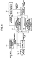
- FIG. 6 shows a constitution in which a detecting section and a phase shift vector generating section are separately provided, only a phase shift vector and the ratio of average power to noise power of a phase shift estimated vector per symbol of a series of synchronism establishment signals are calculated in advance to reduce operation amount.
- each of the pilot interpolated vector generating parts 14 and 15 calculates a pilot interpolated phase shift vector by the above-stated interpolation method and outputs the vector to the detection circuit 17. At the same time, each of the pilot interpolated vector generating parts 14 and 15 calculates the ratio of vector power to noise per symbol of a series of synchronism establishment signals and outputs the ratio to the detection output selection circuit 16.
- the detection output selection circuit 16 selects a better interpolation method from the received power to noise ratio and outputs a selection signal to the detection circuit 17.
- the detection circuit 17 performs detection processing to a reception signal data section using the vector of the interpolation method designated by the selection signal and outputs the vector as a detection signal.
- the receiving apparatus of spectrum spread communication system shown in FIG. 6 can be constituted to have only one detection circuit while obtaining the equivalent detection characteristics to those of the receiving apparatus of spectrum spread communication system shown in FIG. 1.
- the present invention has a plurality of detection circuits corresponding to a plurality of fading pitches. By selecting the detection output, it is possible to follow up the variation of the fading pitch at high speed. Thus, even if the fading pitch is varied, it is possible to obtain good reception characteristics.
Landscapes
- Engineering & Computer Science (AREA)
- Computer Networks & Wireless Communication (AREA)
- Signal Processing (AREA)
- Synchronisation In Digital Transmission Systems (AREA)
- Digital Transmission Methods That Use Modulated Carrier Waves (AREA)
- Cable Transmission Systems, Equalization Of Radio And Reduction Of Echo (AREA)
- Radio Relay Systems (AREA)
- Mobile Radio Communication Systems (AREA)
- Circuits Of Receivers In General (AREA)
Abstract
Description
Claims (8)
- A receiving apparatus of spectrum spread communication system used in a code division multiple access system, said receiving apparatus comprising:a plurality of detection circuits, each has optimum detection characteristics of receiving signals under different fading pitches;a detection output selection circuit, which determines one of detection circuits performing better detection result than others; anda selector, which selects output signals from the detection circuit determined by the detection output selection circuit as output signals of the receiving apparatus.
- A receiving apparatus of spectrum spread communication system used in a code division multiple access system, said receiving apparatus comprising:a plurality of detection circuits, each has optimum detection characteristics of receiving signals under different fading pitches, and outputs a judging signal indicating the detection result having being detected and detected signals;a detection output selection circuit, which determines one of detection circuits performing better detection result than others by comparing the judging signal from each detection circuit, and outputs a selection signal indicating the detection circuit from which output signals are to be selected as output signals of the receiving apparatus; anda selector, which selects output signals from the detection circuit indicated by the selection signal for providing output signals of the receiving apparatus.
- The receiving apparatus according to claim 2, wherein said judging signal is a ratio of average power to noise power of the phase shift estimated vector per one symbol of the series of synchronism establishment signals.
- A receiving apparatus of spectrum spread communication system used in a code division multiple access system, said receiving apparatus comprising:a synchronism establishment circuit, which correlates a series of input data to a series of signals obtained by spreading a series of synchronism establishment signals using a spread code, and outputs a synchronization signal;a data buffer, which stores the series of input data and outputs the input data synchronous with the synchronization signal;a correlator, which performs a correlation calculation between a reception signal from the data buffer and the spread code synchronously with the synchronization signal, and outputs a correlation value;a plurality of detection circuits, each has optimum detection characteristics of receiving signals under different fading pitches, compensates receiving signals in consideration of a phase shift based on the correlation value and the synchronization signal, and outputs a judging signal indicating the detection result having being detected and detected signals as demodulation signals;a detection output selection circuit, which outputs a selection signal indicating one of the detection circuits performing better detection result than others by comparing the judging signal from each detection circuit; anda selector, which selects demodulation signals from the detection circuit indicated by the selection signal, and outputs the demodulation signals as output signals of the receiving apparatus.
- The receiving apparatus according to claim 4, wherein said judging signal is a ratio of average power to noise power of the phase shift estimated vector per one symbol of the series of synchronism establishment signals.
- A receiving apparatus of spectrum spread communication system used in a code division multiple access system, said receiving apparatus comprising:a synchronism establishment circuit, which correlates a series of input data to a series of signals obtained by spreading a series of synchronism establishment signals using a spread code, and outputs a synchronization signal;a data buffer, which stores the series of input data and outputs the input data synchronous with the synchronization signal;a correlator, which performs a correlation calculation between a reception signal from the data buffer and the spread code synchronously with the synchronization signal, and outputs a correlation value;a first detection circuit, which has optimum detection characteristics of receiving signals under a low speed fading pitch, compensates receiving signals in consideration of a phase shift based on the correlation value and the synchronization signal, and outputs a first judging signal indicating the detection result having being detected and first detected signals as demodulation signals;a second detection circuit, which has optimum detection characteristics of receiving signals under a high speed fading pitch, compensates receiving signals in consideration of a phase shift based on the correlation value and the synchronization signal, and outputs a second judging signal indicating the detection result having being detected and second detected signals as demodulation signals;a detection output selection circuit, which outputs a selection signal indicating one of the first detection circuit and the second detection circuit performing better detection result than other by comparing the first judging signal and the second judging signal; anda selector, which selects demodulation signals from one of the first detection circuit and the second detection circuit indicated by the selection signal, and outputs the demodulation signals as output signals of the receiving apparatus.
- The receiving apparatus according to claim 6, wherein said judging signal is a ratio of average power to noise power of the phase shift estimated vector per one symbol of the series of synchronism establishment signals.
- A receiving apparatus of spectrum spread communication system used in a code division multiple access system, said receiving apparatus comprising:a synchronism establishment circuit, which correlates a series of input data to a series of signals obtained by spreading a series of synchronism establishment signals using a spread code, and outputs a synchronization signal;a data buffer, which stores the series of input data and outputs the input data synchronous with the synchronization signal;a correlator, which performs a correlation calculation between a reception signal from the data buffer and the spread code synchronously with the synchronization signal, and outputs a correlation value;a plurality of phase shift vector generating sections, each has optimum calculation characteristics of receiving signals under different fading pitches, calculates a phase shift vector of receiving signals based on the correlation value and the synchronization signal, and outputs the calculated phase shift vector of receiving signals and a judging signal indicating a ratio of average power to noise power of the phase shift estimated vector per one symbol of the series of synchronism establishment signals;a detection output selection circuit, which outputs a selection signal indicating one of the phase shift vector generating sections being considered obtaining a better result of calculation than others by comparing the judging signal from each phase shift vector generating section; anda detection circuit, which selects the phase shift vector of receiving signals from the phase shift vector generating section indicated by the selection signal, performs detection operation of receiving signals by using the phase shift vector of receiving signals and the synchronization signal, and outputs signals being detected as output signals of the receiving apparatus.
Applications Claiming Priority (2)
| Application Number | Priority Date | Filing Date | Title |
|---|---|---|---|
| JP9090199A JP3336991B2 (en) | 1999-03-31 | 1999-03-31 | Receiver for spread spectrum communication |
| JP9090199 | 1999-03-31 |
Publications (3)
| Publication Number | Publication Date |
|---|---|
| EP1041726A2 true EP1041726A2 (en) | 2000-10-04 |
| EP1041726A3 EP1041726A3 (en) | 2003-02-26 |
| EP1041726B1 EP1041726B1 (en) | 2005-06-08 |
Family
ID=14011313
Family Applications (1)
| Application Number | Title | Priority Date | Filing Date |
|---|---|---|---|
| EP20000106641 Expired - Lifetime EP1041726B1 (en) | 1999-03-31 | 2000-03-28 | Receiving apparatus for a spread spectrum communication system |
Country Status (7)
| Country | Link |
|---|---|
| US (1) | US6522686B1 (en) |
| EP (1) | EP1041726B1 (en) |
| JP (1) | JP3336991B2 (en) |
| KR (1) | KR100382133B1 (en) |
| CN (1) | CN1268822A (en) |
| BR (1) | BR0001111A (en) |
| DE (1) | DE60020632T2 (en) |
Cited By (1)
| Publication number | Priority date | Publication date | Assignee | Title |
|---|---|---|---|---|
| WO2006027603A1 (en) * | 2004-09-10 | 2006-03-16 | Ttpcom Limited | Method and apparatus for selecting a channel filter for a communication system |
Families Citing this family (3)
| Publication number | Priority date | Publication date | Assignee | Title |
|---|---|---|---|---|
| KR100770899B1 (en) * | 2001-10-12 | 2007-10-26 | 삼성전자주식회사 | Demodulation method and apparatus for mobile communication system supporting multi-level modulation |
| TWI256815B (en) * | 2004-07-27 | 2006-06-11 | Mediatek Inc | Frequency synchronization device and the method thereof |
| US8170087B2 (en) * | 2007-05-10 | 2012-05-01 | Texas Instruments Incorporated | Correlation coprocessor |
Family Cites Families (8)
| Publication number | Priority date | Publication date | Assignee | Title |
|---|---|---|---|---|
| JPH0537490A (en) | 1991-08-02 | 1993-02-12 | Nippon Telegr & Teleph Corp <Ntt> | Spread spectrum radio communication system |
| JPH0746168A (en) * | 1993-07-27 | 1995-02-14 | Matsushita Electric Ind Co Ltd | Diversity receiver |
| DE69629633T2 (en) * | 1995-07-19 | 2004-06-17 | Nec Corp. | Diversity messaging system with code division multiple access |
| JP2723094B2 (en) | 1995-11-07 | 1998-03-09 | 日本電気株式会社 | CDMA receiver |
| JP3286189B2 (en) * | 1996-11-14 | 2002-05-27 | 松下電器産業株式会社 | Receiver using algorithm diversity |
| JPH10190497A (en) | 1996-12-27 | 1998-07-21 | Fujitsu Ltd | SIR measurement device |
| US5710995A (en) * | 1997-01-16 | 1998-01-20 | Ford Motor Company | Adaptive antenna receiver |
| JP2853741B2 (en) | 1997-06-03 | 1999-02-03 | 日本電気株式会社 | CDMA receiver |
-
1999
- 1999-03-31 JP JP9090199A patent/JP3336991B2/en not_active Expired - Fee Related
-
2000
- 2000-03-28 DE DE2000620632 patent/DE60020632T2/en not_active Expired - Fee Related
- 2000-03-28 EP EP20000106641 patent/EP1041726B1/en not_active Expired - Lifetime
- 2000-03-30 KR KR1020000016425A patent/KR100382133B1/en not_active Expired - Fee Related
- 2000-03-30 CN CN00105537A patent/CN1268822A/en active Pending
- 2000-03-30 US US09/538,514 patent/US6522686B1/en not_active Expired - Fee Related
- 2000-03-31 BR BR0001111A patent/BR0001111A/en not_active IP Right Cessation
Cited By (2)
| Publication number | Priority date | Publication date | Assignee | Title |
|---|---|---|---|---|
| WO2006027603A1 (en) * | 2004-09-10 | 2006-03-16 | Ttpcom Limited | Method and apparatus for selecting a channel filter for a communication system |
| US8743910B2 (en) | 2004-09-10 | 2014-06-03 | Mstar Semiconductor, Inc. | Method and apparatus for selecting a channel filter for a communication system |
Also Published As
| Publication number | Publication date |
|---|---|
| KR100382133B1 (en) | 2003-05-01 |
| DE60020632D1 (en) | 2005-07-14 |
| CN1268822A (en) | 2000-10-04 |
| KR20000076990A (en) | 2000-12-26 |
| DE60020632T2 (en) | 2006-05-04 |
| EP1041726B1 (en) | 2005-06-08 |
| JP3336991B2 (en) | 2002-10-21 |
| JP2000286753A (en) | 2000-10-13 |
| EP1041726A3 (en) | 2003-02-26 |
| US6522686B1 (en) | 2003-02-18 |
| BR0001111A (en) | 2000-10-31 |
Similar Documents
| Publication | Publication Date | Title |
|---|---|---|
| KR100275613B1 (en) | Cdma receiving apparatus | |
| US20020181557A1 (en) | Communication terminal apparatus and demodulation method | |
| US6188679B1 (en) | CDMA chip synchronization circuit | |
| KR100220140B1 (en) | Apparatus and Method for Initial Synchronization of Spread Spectrum Codes in CDM Transmission System | |
| KR100711842B1 (en) | A Method and device of the estimating carrier frequency offset of subscriber terminal | |
| EP0940927A2 (en) | Cellular system, mobile portable apparatus, base station apparatus, optimum path detecting method, and apparatus thereof | |
| US20030153277A1 (en) | Wireless receiver estimating power of interference | |
| JPH118606A (en) | Adaptive rake reception system | |
| KR20010052444A (en) | Multipath propagation delay determining means using periodically inserted pilot symbols | |
| US6628700B1 (en) | CDMA reception method and CDMA receiver | |
| EP1032138B1 (en) | Reception path search method and searcher circuit of CDMA reception device | |
| EP1499032A1 (en) | Sir measurement device and method | |
| EP0978950A2 (en) | Decode circuit for code devision multiple access receiver | |
| EP1280282B1 (en) | Apparatus and method for measuring SIR in a Rake-receiver | |
| EP1041726B1 (en) | Receiving apparatus for a spread spectrum communication system | |
| JP3588089B2 (en) | CDMA receiving apparatus, mobile station apparatus and base station apparatus | |
| EP1148657A2 (en) | Demodulation apparatus and demodulation method for mobile communication | |
| EP1047201A2 (en) | CDMA receiver | |
| JP2001189768A (en) | Synchronous detector | |
| US20040259517A1 (en) | Apparatus and method for reception | |
| US7269437B2 (en) | Transmission power control circuit using W-CDMA method | |
| JP2002084568A (en) | Cell search method for mobile station in CDMA mobile communication system, and CDMA mobile communication system | |
| KR100347512B1 (en) | Neighbor Cell Search scheme and method for W-CDMA Mobile station | |
| US20030165185A1 (en) | Receiving device and receiving method | |
| KR102869663B1 (en) | Apparatus and method for estimating frequency offset based on correlation value |
Legal Events
| Date | Code | Title | Description |
|---|---|---|---|
| PUAI | Public reference made under article 153(3) epc to a published international application that has entered the european phase |
Free format text: ORIGINAL CODE: 0009012 |
|
| AK | Designated contracting states |
Kind code of ref document: A2 Designated state(s): AT BE CH CY DE DK ES FI FR GB GR IE IT LI LU MC NL PT SE |
|
| AX | Request for extension of the european patent |
Free format text: AL;LT;LV;MK;RO;SI |
|
| PUAL | Search report despatched |
Free format text: ORIGINAL CODE: 0009013 |
|
| AK | Designated contracting states |
Kind code of ref document: A3 Designated state(s): AT BE CH CY DE DK ES FI FR GB GR IE IT LI LU MC NL PT SE |
|
| AX | Request for extension of the european patent |
Extension state: AL LT LV MK RO SI |
|
| 17P | Request for examination filed |
Effective date: 20030117 |
|
| 17Q | First examination report despatched |
Effective date: 20030512 |
|
| AKX | Designation fees paid |
Designated state(s): DE GB |
|
| RTI1 | Title (correction) |
Free format text: RECEIVING APPARATUS FOR A SPREAD SPECTRUM COMMUNICATION SYSTEM |
|
| GRAP | Despatch of communication of intention to grant a patent |
Free format text: ORIGINAL CODE: EPIDOSNIGR1 |
|
| GRAS | Grant fee paid |
Free format text: ORIGINAL CODE: EPIDOSNIGR3 |
|
| GRAA | (expected) grant |
Free format text: ORIGINAL CODE: 0009210 |
|
| AK | Designated contracting states |
Kind code of ref document: B1 Designated state(s): DE GB |
|
| REG | Reference to a national code |
Ref country code: GB Ref legal event code: FG4D |
|
| REF | Corresponds to: |
Ref document number: 60020632 Country of ref document: DE Date of ref document: 20050714 Kind code of ref document: P |
|
| PLBE | No opposition filed within time limit |
Free format text: ORIGINAL CODE: 0009261 |
|
| STAA | Information on the status of an ep patent application or granted ep patent |
Free format text: STATUS: NO OPPOSITION FILED WITHIN TIME LIMIT |
|
| 26N | No opposition filed |
Effective date: 20060309 |
|
| PGFP | Annual fee paid to national office [announced via postgrant information from national office to epo] |
Ref country code: DE Payment date: 20070322 Year of fee payment: 8 |
|
| PGFP | Annual fee paid to national office [announced via postgrant information from national office to epo] |
Ref country code: GB Payment date: 20070328 Year of fee payment: 8 |
|
| GBPC | Gb: european patent ceased through non-payment of renewal fee |
Effective date: 20080328 |
|
| PG25 | Lapsed in a contracting state [announced via postgrant information from national office to epo] |
Ref country code: DE Free format text: LAPSE BECAUSE OF NON-PAYMENT OF DUE FEES Effective date: 20081001 |
|
| PG25 | Lapsed in a contracting state [announced via postgrant information from national office to epo] |
Ref country code: GB Free format text: LAPSE BECAUSE OF NON-PAYMENT OF DUE FEES Effective date: 20080328 |