EP1041682A1 - Cable connector in which two contacts clamp a wire core of a cable therebetween - Google Patents
Cable connector in which two contacts clamp a wire core of a cable therebetween Download PDFInfo
- Publication number
- EP1041682A1 EP1041682A1 EP00106708A EP00106708A EP1041682A1 EP 1041682 A1 EP1041682 A1 EP 1041682A1 EP 00106708 A EP00106708 A EP 00106708A EP 00106708 A EP00106708 A EP 00106708A EP 1041682 A1 EP1041682 A1 EP 1041682A1
- Authority
- EP
- European Patent Office
- Prior art keywords
- base
- insulator
- cable
- contact
- core wire
- Prior art date
- Legal status (The legal status is an assumption and is not a legal conclusion. Google has not performed a legal analysis and makes no representation as to the accuracy of the status listed.)
- Granted
Links
Images






Classifications
-
- H—ELECTRICITY
- H01—ELECTRIC ELEMENTS
- H01R—ELECTRICALLY-CONDUCTIVE CONNECTIONS; STRUCTURAL ASSOCIATIONS OF A PLURALITY OF MUTUALLY-INSULATED ELECTRICAL CONNECTING ELEMENTS; COUPLING DEVICES; CURRENT COLLECTORS
- H01R12/00—Structural associations of a plurality of mutually-insulated electrical connecting elements, specially adapted for printed circuits, e.g. printed circuit boards [PCB], flat or ribbon cables, or like generally planar structures, e.g. terminal strips, terminal blocks; Coupling devices specially adapted for printed circuits, flat or ribbon cables, or like generally planar structures; Terminals specially adapted for contact with, or insertion into, printed circuits, flat or ribbon cables, or like generally planar structures
- H01R12/50—Fixed connections
- H01R12/59—Fixed connections for flexible printed circuits, flat or ribbon cables or like structures
- H01R12/592—Fixed connections for flexible printed circuits, flat or ribbon cables or like structures connections to contact elements
-
- H—ELECTRICITY
- H01—ELECTRIC ELEMENTS
- H01R—ELECTRICALLY-CONDUCTIVE CONNECTIONS; STRUCTURAL ASSOCIATIONS OF A PLURALITY OF MUTUALLY-INSULATED ELECTRICAL CONNECTING ELEMENTS; COUPLING DEVICES; CURRENT COLLECTORS
- H01R12/00—Structural associations of a plurality of mutually-insulated electrical connecting elements, specially adapted for printed circuits, e.g. printed circuit boards [PCB], flat or ribbon cables, or like generally planar structures, e.g. terminal strips, terminal blocks; Coupling devices specially adapted for printed circuits, flat or ribbon cables, or like generally planar structures; Terminals specially adapted for contact with, or insertion into, printed circuits, flat or ribbon cables, or like generally planar structures
- H01R12/50—Fixed connections
- H01R12/59—Fixed connections for flexible printed circuits, flat or ribbon cables or like structures
- H01R12/594—Fixed connections for flexible printed circuits, flat or ribbon cables or like structures for shielded flat cable
- H01R12/596—Connection of the shield to an additional grounding conductor, e.g. drain wire
-
- H—ELECTRICITY
- H01—ELECTRIC ELEMENTS
- H01R—ELECTRICALLY-CONDUCTIVE CONNECTIONS; STRUCTURAL ASSOCIATIONS OF A PLURALITY OF MUTUALLY-INSULATED ELECTRICAL CONNECTING ELEMENTS; COUPLING DEVICES; CURRENT COLLECTORS
- H01R12/00—Structural associations of a plurality of mutually-insulated electrical connecting elements, specially adapted for printed circuits, e.g. printed circuit boards [PCB], flat or ribbon cables, or like generally planar structures, e.g. terminal strips, terminal blocks; Coupling devices specially adapted for printed circuits, flat or ribbon cables, or like generally planar structures; Terminals specially adapted for contact with, or insertion into, printed circuits, flat or ribbon cables, or like generally planar structures
- H01R12/70—Coupling devices
- H01R12/77—Coupling devices for flexible printed circuits, flat or ribbon cables or like structures
- H01R12/771—Details
- H01R12/772—Strain relieving means
-
- H—ELECTRICITY
- H01—ELECTRIC ELEMENTS
- H01R—ELECTRICALLY-CONDUCTIVE CONNECTIONS; STRUCTURAL ASSOCIATIONS OF A PLURALITY OF MUTUALLY-INSULATED ELECTRICAL CONNECTING ELEMENTS; COUPLING DEVICES; CURRENT COLLECTORS
- H01R12/00—Structural associations of a plurality of mutually-insulated electrical connecting elements, specially adapted for printed circuits, e.g. printed circuit boards [PCB], flat or ribbon cables, or like generally planar structures, e.g. terminal strips, terminal blocks; Coupling devices specially adapted for printed circuits, flat or ribbon cables, or like generally planar structures; Terminals specially adapted for contact with, or insertion into, printed circuits, flat or ribbon cables, or like generally planar structures
- H01R12/70—Coupling devices
- H01R12/77—Coupling devices for flexible printed circuits, flat or ribbon cables or like structures
- H01R12/778—Coupling parts carrying sockets, clips or analogous counter-contacts
-
- Y—GENERAL TAGGING OF NEW TECHNOLOGICAL DEVELOPMENTS; GENERAL TAGGING OF CROSS-SECTIONAL TECHNOLOGIES SPANNING OVER SEVERAL SECTIONS OF THE IPC; TECHNICAL SUBJECTS COVERED BY FORMER USPC CROSS-REFERENCE ART COLLECTIONS [XRACs] AND DIGESTS
- Y10—TECHNICAL SUBJECTS COVERED BY FORMER USPC
- Y10T—TECHNICAL SUBJECTS COVERED BY FORMER US CLASSIFICATION
- Y10T29/00—Metal working
- Y10T29/49—Method of mechanical manufacture
- Y10T29/49002—Electrical device making
- Y10T29/49117—Conductor or circuit manufacturing
- Y10T29/49169—Assembling electrical component directly to terminal or elongated conductor
- Y10T29/49171—Assembling electrical component directly to terminal or elongated conductor with encapsulating
- Y10T29/49172—Assembling electrical component directly to terminal or elongated conductor with encapsulating by molding of insulating material
-
- Y—GENERAL TAGGING OF NEW TECHNOLOGICAL DEVELOPMENTS; GENERAL TAGGING OF CROSS-SECTIONAL TECHNOLOGIES SPANNING OVER SEVERAL SECTIONS OF THE IPC; TECHNICAL SUBJECTS COVERED BY FORMER USPC CROSS-REFERENCE ART COLLECTIONS [XRACs] AND DIGESTS
- Y10—TECHNICAL SUBJECTS COVERED BY FORMER USPC
- Y10T—TECHNICAL SUBJECTS COVERED BY FORMER US CLASSIFICATION
- Y10T29/00—Metal working
- Y10T29/49—Method of mechanical manufacture
- Y10T29/49002—Electrical device making
- Y10T29/49117—Conductor or circuit manufacturing
- Y10T29/49174—Assembling terminal to elongated conductor
- Y10T29/49181—Assembling terminal to elongated conductor by deforming
-
- Y—GENERAL TAGGING OF NEW TECHNOLOGICAL DEVELOPMENTS; GENERAL TAGGING OF CROSS-SECTIONAL TECHNOLOGIES SPANNING OVER SEVERAL SECTIONS OF THE IPC; TECHNICAL SUBJECTS COVERED BY FORMER USPC CROSS-REFERENCE ART COLLECTIONS [XRACs] AND DIGESTS
- Y10—TECHNICAL SUBJECTS COVERED BY FORMER USPC
- Y10T—TECHNICAL SUBJECTS COVERED BY FORMER US CLASSIFICATION
- Y10T29/00—Metal working
- Y10T29/49—Method of mechanical manufacture
- Y10T29/49002—Electrical device making
- Y10T29/49117—Conductor or circuit manufacturing
- Y10T29/49174—Assembling terminal to elongated conductor
- Y10T29/49181—Assembling terminal to elongated conductor by deforming
- Y10T29/49185—Assembling terminal to elongated conductor by deforming of terminal
- Y10T29/49192—Assembling terminal to elongated conductor by deforming of terminal with insulation removal
-
- Y—GENERAL TAGGING OF NEW TECHNOLOGICAL DEVELOPMENTS; GENERAL TAGGING OF CROSS-SECTIONAL TECHNOLOGIES SPANNING OVER SEVERAL SECTIONS OF THE IPC; TECHNICAL SUBJECTS COVERED BY FORMER USPC CROSS-REFERENCE ART COLLECTIONS [XRACs] AND DIGESTS
- Y10—TECHNICAL SUBJECTS COVERED BY FORMER USPC
- Y10T—TECHNICAL SUBJECTS COVERED BY FORMER US CLASSIFICATION
- Y10T29/00—Metal working
- Y10T29/49—Method of mechanical manufacture
- Y10T29/49002—Electrical device making
- Y10T29/49117—Conductor or circuit manufacturing
- Y10T29/49194—Assembling elongated conductors, e.g., splicing, etc.
-
- Y—GENERAL TAGGING OF NEW TECHNOLOGICAL DEVELOPMENTS; GENERAL TAGGING OF CROSS-SECTIONAL TECHNOLOGIES SPANNING OVER SEVERAL SECTIONS OF THE IPC; TECHNICAL SUBJECTS COVERED BY FORMER USPC CROSS-REFERENCE ART COLLECTIONS [XRACs] AND DIGESTS
- Y10—TECHNICAL SUBJECTS COVERED BY FORMER USPC
- Y10T—TECHNICAL SUBJECTS COVERED BY FORMER US CLASSIFICATION
- Y10T29/00—Metal working
- Y10T29/51—Plural diverse manufacturing apparatus including means for metal shaping or assembling
- Y10T29/5193—Electrical connector or terminal
Definitions
- the present invention relates to a connector for a cable and, in particular, to a cable connector suitable for a ribbon-shaped flat cable with core wires arranged at a narrow pitch.
- wire connection is carried out by using a method in which a core wire of a cable is press-fitted into a slit formed on a press-contact portion of a contact to bring the core wire into press-contact with the contact, or another method in which a core wire of a cable is wrapped or enveloped by a crimping portion of a contact to crimp the core wire to the contact.
- the press-contact piece or the crimping piece of the contact is no longer adaptable to a present-day multi-wire cable in which core wires are arranged at a narrower pitch.
- an invention has been made of a connector in which a core wire of a cable is brought into direct contact with a side surface of a contact without providing the contact with a press-contact piece or a crimping piece, as disclosed in Japanese Unexamined Patent Publications (JP-A) Nos. H05-101853 and H10-255921.
- a first and a second fix/hold member clamp a coated wire with its core wire exposed.
- the first and the second fix/hold members are engaged with a fix/hold member attaching portion on a support plate while a center portion of the exposed core wire is placed on a core wire support portion. Furthermore, an end portion of the exposed core wire is placed on an end holding portion of the supporting plate.
- a male connector is formed. Thereafter, the male connector is inserted into a cylindrical female connector in a longitudinal direction of the coated wire to bring the exposed core wire into press-contact with the contact. In the above-mentioned manner, the exposed core wire is connected to the contact.
- clamping of the coated wire and wire connection can not simultaneously be carried out and therefore required troublesome operations.
- the male connector is inserted into the female connector in the longitudinal direction of the coated wire and, within the female connector, the core wire of the coated wire is pressed against the contact in the thickness direction of the male connector. Therefore, it is required to provide a pressing slider for pressing the core wire against the contact and a pressing protrusion for driving the pressing slider in the thickness direction of the male connector. This results in a complicated structure and a disadvantage in production cost.
- the connector disclosed in JP-A H10-255921 uses a cable conductor as a plug of the connector.
- a plurality of cables are arrayed on a cable holder by a cable array arranging portion (this corresponds to the clamping operation).
- each cable conductor is placed in a cable guide groove of the cable holder.
- the cable conductor is bent into a U-shape to be wound around an end portion of the cable holder.
- An end of the cable conductor is adhered to the cable holder by lamination (this corresponds to the wire-connecting operation).
- the above-described connector also requires troublesome operations because the clamping of the cable and the wire connection can not simultaneously be performed.
- the cable array arranging portion and the lamination are required. This results in a disadvantage in production cost.
- a cable connector for use in connecting a cable having a core wire
- the cable connector comprising a base insulator, a base contact coupled to the base insulator, and a pressing device for pressing the core wire against the base contact in a predetermined direction intersecting the core wire
- the pressing device comprising a cover insulator coupled to the base insulator and movable in the predetermined direction, a partition wall formed integral with the cover insulator for positioning the core wire to make the core wire face the base contact in the predetermined direction, and a support contact coupled to the cover insulator and cooperated with the base contact for clamping the core wire therebetween with movement of the cover insulator towards the base insulator.
- the cable connector is designated by a reference numeral 1 and comprises a base insulator 2, a plurality of base contacts 3, two cover insulators 4, and a plurality of support contacts 5.
- the cable connector 1 is for connecting a flattened coaxial cable 8 with a drain wire to a mating connector (not shown) as an object of connection.
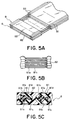
- the flattened coaxial cable 8 comprises a plurality of coaxial cables 81 with the drain wire and an UV-setting resin or film 82 coupling the coaxial cables 81.
- each of the coaxial cables 81 comprises a signal wire 81a, a dielectric member 81b surrounding the signal wire 81a, a drain wire 81c extending in parallel to the signal wire 81a, a shield 81d, and a sheath 81e.
- the shield 81d covers the signal wire 81a, the dielectric member 81b, and the drain wire 81c.
- the sheath 81e accommodates the signal wire 81a, the dielectric member 81b, the drain wire 81c, and the shield 81d.
- the signal wire 81a and the drain wire 81c will collectively be called as a core wire.
- the base insulator 2 has a flat-plate portion 21, a fitting portion 22, and protrusions 23 as a first clamp portion.
- the flat-plate portion 21 has a plate-like shape and adapted to receive and support the coaxial cable 8 in its thickness direction.
- the flat-plate portion 21 is provided with a stopper 21a for preventing the displacement of the base contact 3 in the direction perpendicular to the drawing sheet of Fig. 1.
- the fitting portion 22 is a portion to be engaged with the mating connector and is formed integral with one end of the flat-plate portion 21.
- the protrusions 23 are formed at the other end of the flat-plate portion 21 to integrally protrude from the upper and the lower surfaces thereof, respectively. The protrusions 23 serve to clamp the coaxial cable 8 in a predetermined direction A1.
- Each of the base contacts 3 has a clamping portion 31 for clamping the core wire of the coaxial cable 8, a core wire contacting portion 32 formed at one end of the clamping portion 31 to be contacted with the core wire, a press-fitted portion 33 formed at one end of the core wire contacting portion 32 to be press-fitted into the fitting portion 22, a mating connector contacting portion 34 formed at one end of the press-fit portion 33 to be brought into contact with the mating connector and a base-side elastic contacting spring 35 formed at the other end of the clamping portion 31 to press the core wire against the support contact 5.
- the base contacts 3 are press-fitted into the fitting portion 22 at a predetermined pitch on the upper and the lower surfaces of the flat-plate portion 21.
- Each of the cover insulators 4 has a generally flat plate-shape and comprises a plurality of contact holding portions 41 formed at its one end to be faced to the base contacts 3 in the predetermined direction A1, partition walls 42 formed on both sides of each contact holding portions 41 to position the core wire with respect to the support contact 5 and the base contact 3, and a clamp valley 43 as a second clamping portion which is formed on the side of the base insulator 2 at the other end of the cover insulator 4 to clamp, in the predetermined direction A1, the coaxial cable 8 at its end surface in its thickness direction in cooperation with the protrusions 23.
- the partition wall 42 is provided with a recess 42a to avoid contact with the stopper 21a formed on the base insulator 2.
- the two cover insulators 4 are abutted or assembled to the base insulator 2 to sandwich the base insulator 2 therebetween in the above-mentioned predetermined direction a.
- the cover insulators are coupled to each other by the use of screws 44 to be fixed to the base insulator 2 as shown in Fig. 4B.
- Each of the support contacts 5 is generally E-shaped and comprises a clamping portion 51 for clamping the core wire of the coaxial cable 8 in cooperation with the clamping portion 31 of the base contact 3 where the cover insulators 4 are abutted to the base insulator 2, a support-side elastic contacting spring 52 formed at one end of the clamping portion 51 to press the core wire against the core wire contacting portion 32 of the base contact 3, a press-fit portion 53 formed at the center portion of the clamping portion 51 to be press-fitted into the contact holding portion 41 of the cover insulator 4, and a receiving portion 54 formed at the other end of the clamping portion 51 to be faced to the base-side elastic contacting spring 35 of the base contact 3 and to receive the core wire pressed by the base side elastic contacting spring 35.
- Each of the support contacts 5 is arranged between the partition wails 42 by press-fitting the press-fit portion 53 into the contact holding portion 41 of the cover insulator 4. Next, description will be made about a wire connection method for connecting the flattened coaxial cable 8 to the cable connector 1.
- the UV-setting resin 82, the sheath 81e, the shield 81d, and the dielectric member 81b are cut off in the vicinity of a terminal end of the coaxial cable 8. A portion between the cut-off portion and the terminal end is displaced toward the terminal end of the cable as far as it is not released from the signal wire 81a and the drain wire 81c. Thus, a part of each of the signal wire 81a and the drain wire 81c is half-stripped as shown in Figs. 5A and 5B.
- the coaxial cable 8 is then placed on the cover insulator 4, as shown above the base insulator 2 illustrated in Figs. 1 to 3. At this time, each of the signal wire 81a and the drain wire 81c of the coaxial cable 8 is arranged between the partition walls 42 to bring each of the signal wire 81a and the drain wire 81c into contact with the support contact 5.
- the cover insulator 4 with the coaxial cable 8 arranged thereon is abutted to the base insulator 2 together with the coaxial cable 8 in the predetermined direction A1, as shown below the base insulator 2 illustrated in Figs. 1 to 3.
- each of the signal wire 81a and the drain wire 81 of the coaxial cable 8 is clamped by the base contact 3 and the support contact 5 so that each of the signal wire 81a and the drain wire 81c is connected to the base contact 3.
- the coaxial cable 8 is clamped by the protrusions 23 and the clamp valley 43 in the predetermined direction A1 at an unexposed portion where the signal wire 81a and the drain wire 81c are not exposed.
- each of the signal wire 81a and the drain wire 81c is electrically connected to the base contact 3 at least at two points, namely points P1 and P2, by the base side elastic contacting spring 35 and the support side elastic contacting spring 52. Then, as shown in Figs. 4A-4C, the cover insulators 4 abutted to the base insulator 2 from the upper and the lower sides are coupled to each other by the use of the screws 44 to fix the cover insulators 4 to the base insulator 2.
- the description will be made as regards a cable connector according to a second embodiment of the present invention. Similar parts are designated by like reference numerals.
- the base-side elastic contacting springs 35 are formed integral with both ends of the clamping portion 31 of the base contact 3.
- the receiving portions 54 are formed integral with both ends of the support contact 5.
- the base-side elastic contacting springs 35 of the base contact 3 clamp the core wire of the coaxial cable 8 in cooperation with the receiving portions 54 of the support contact 5.
- the description will be made as regards a cable connector according to a third embodiment of the present invention. Similar parts are designated by like reference numerals.
- the core wire contacting portion 32 is formed integral with the center of the clamping portion 31 of the base contact 3.
- a pair of the support-side elastic contacting springs 52 are formed integral with the clamping portion 51 of the support contact 5.
- the press-fit portion 53 is formed integral with one end of the clamping portion 51. The above-mentioned pair of support-side elastic contacting springs 52 clamp the core wire of the coaxial cable 8 and press the core wire against the core wire contacting portion 32.
- the cover insulator 4 comprises a cover insulator body 40 having the clamp valley (not shown) and the contact holding portion 41 which is a component separate from the cover insulator body 40, which has the partition wall 42, and which is removable from the cover insulator main body 40.
- the base insulator 2 is also provided with a partition wall 24.
- the fourth embodiment has a structure substantially same to that of the first embodiment if the contact holding portion 41 is attached to the cover insulator body 40. However, in the fourth embodiment, it is possible to perform connection of the core wire as a last step by attaching the contact holding portion 41 to the cover insulator body 40 after the cover insulator body 40 is fixed to the base insulator 2.
- the description will be made as regards a cable connector according to a fifth embodiment of the present invention. Similar parts are designated by like reference numerals.
- the core wire contacting portions 32 are formed integral with both ends of the clamping portion 31 of the base contact 3.
- the support-side elastic contacting springs 52 are formed integral with both ends of the clamping portion 51 of the support contact 5.
- the most characteristic part of this embodiment is the contact holding portion 41 of the cover insulator 4.
- the contact holding portion 41 is adapted to press the core wire of the coaxial cable 8 against the base contact 3 in cooperation with the support contact 5.
- the cable connector 1 of Fig. 10 is generally similar in structure to the cable connector of Fig. 9.
- the contact holding portion 41 of the cover insulator 4 is not adapted to press the core wire of the coaxial cable 8 against the base contact 3.
- the support contact 5 is press-fitted into the contact holding portion 41 so that the clamping portion 51 is located at one side of the contact holding portion 41 faced to base insulator 2.
- the description will be made as regards a cable connector according to a seventh embodiment of the present invention. Similar parts are designated by like reference numerals.
- the core wire contacting portion 32 is formed integral with one end of the clamping portion 31 of the base contact 3 while nothing is provided at the other end of the clamping portion 31.
- the first support-side elastic contacting spring 52 is formed at one end of the clamping portion 51 of the support contact 5 while the second support-side elastic contacting spring 52' is formed at the other end of the clamping portion 51 to be aligned therewith.
- the description will be made as regards a cable connector according to an eighth embodiment of the present invention. Similar parts are designated by like reference numerals.
- the core wire contacting portions 32 are formed integral with both ends of the clamping portion 31 of the base contact 3.
- the support-side elastic contacting springs 52 are formed integral with one end and at the center of the clamping portion 51 of the support contact 5.
- the press-fit portion 53 is formed integral with the other end of the clamping portion 51 to be aligned with the clamping portion 51.
- the cable connector 1 of Fig. 13 has a structure such that the relationship between the core wire contacting portion 32 and the support-side elastic contacting spring 52 is reverse to that of the cable connector of Fig. 12.
- the base-side elastic contacting springs 35 are formed integral with one end and with the center of the clamping portion 31 of the base contact 3, the receiving portions 54 being formed at both ends of the clamping portion 51 of the support contact 5.
- the cable connector 1 of Fig. 14 is substantially similar in structure to the cable connector of Fig. 12 except that the cover insulator 4 is not provided with the partition wall. Instead, the base insulator 2 is provided with the partition wall 24.
- the coaxial cable 82 is at first placed on the base insulator 2. Then, the cover insulator 4 is abutted and fixed to the base insulator 2.
- the cover insulator may be fixed to only one surface of the base insulator.
- the partition wall may be formed in each of the cover insulator and the base insulator.
- the partition wall may be formed only on the base insulator.
- the support contact may be connected to the connection object.
- both of the base contact and the support contact may be connected to the connection object.
- the cover insulator may be fixed to the base insulator, for example, by the use of an engaging mechanism such as engaging claws.
- the cable connector can be applied not only to the flattened coaxial cable with a drain wire but also to various common cables.
Landscapes
- Multi-Conductor Connections (AREA)
- Coupling Device And Connection With Printed Circuit (AREA)
- Connector Housings Or Holding Contact Members (AREA)
- Connections By Means Of Piercing Elements, Nuts, Or Screws (AREA)
Abstract
Description
- The present invention relates to a connector for a cable and, in particular, to a cable connector suitable for a ribbon-shaped flat cable with core wires arranged at a narrow pitch.
- In a typical existing cable connector, wire connection is carried out by using a method in which a core wire of a cable is press-fitted into a slit formed on a press-contact portion of a contact to bring the core wire into press-contact with the contact, or another method in which a core wire of a cable is wrapped or enveloped by a crimping portion of a contact to crimp the core wire to the contact.
- In the above-described wire connection methods, however, the press-contact piece or the crimping piece of the contact is no longer adaptable to a present-day multi-wire cable in which core wires are arranged at a narrower pitch.
- In order to solve the above-mentioned problem, an invention has been made of a connector in which a core wire of a cable is brought into direct contact with a side surface of a contact without providing the contact with a press-contact piece or a crimping piece, as disclosed in Japanese Unexamined Patent Publications (JP-A) Nos. H05-101853 and H10-255921.
- In the electrical connector disclosed in JP-A H05-101853, a first and a second fix/hold member clamp a coated wire with its core wire exposed. In this state, the first and the second fix/hold members are engaged with a fix/hold member attaching portion on a support plate while a center portion of the exposed core wire is placed on a core wire support portion. Furthermore, an end portion of the exposed core wire is placed on an end holding portion of the supporting plate. Thus, a male connector is formed. Thereafter, the male connector is inserted into a cylindrical female connector in a longitudinal direction of the coated wire to bring the exposed core wire into press-contact with the contact. In the above-mentioned manner, the exposed core wire is connected to the contact. Thus, in the above-mentioned electrical connector, clamping of the coated wire and wire connection can not simultaneously be carried out and therefore required troublesome operations.
- Moreover, in the above-described electrical connector, the male connector is inserted into the female connector in the longitudinal direction of the coated wire and, within the female connector, the core wire of the coated wire is pressed against the contact in the thickness direction of the male connector. Therefore, it is required to provide a pressing slider for pressing the core wire against the contact and a pressing protrusion for driving the pressing slider in the thickness direction of the male connector. This results in a complicated structure and a disadvantage in production cost.
- On the other hand, the connector disclosed in JP-A H10-255921 uses a cable conductor as a plug of the connector. In this structure, a plurality of cables are arrayed on a cable holder by a cable array arranging portion (this corresponds to the clamping operation). Then, each cable conductor is placed in a cable guide groove of the cable holder. The cable conductor is bent into a U-shape to be wound around an end portion of the cable holder. An end of the cable conductor is adhered to the cable holder by lamination (this corresponds to the wire-connecting operation). Thus, the above-described connector also requires troublesome operations because the clamping of the cable and the wire connection can not simultaneously be performed. In addition, the cable array arranging portion and the lamination are required. This results in a disadvantage in production cost.
- It is therefore an object of the present invention to provide a cable connector which is adaptable to a cable reduced in pitch, which low in cost, and which allows wire connection and clamping of the cable to be simultaneously carried out.
- Other objects of the present invention will become clear as the description proceeds.
- According to the present invention, there is provided a cable connector for use in connecting a cable having a core wire, the cable connector comprising a base insulator, a base contact coupled to the base insulator, and a pressing device for pressing the core wire against the base contact in a predetermined direction intersecting the core wire, the pressing device comprising a cover insulator coupled to the base insulator and movable in the predetermined direction, a partition wall formed integral with the cover insulator for positioning the core wire to make the core wire face the base contact in the predetermined direction, and a support contact coupled to the cover insulator and cooperated with the base contact for clamping the core wire therebetween with movement of the cover insulator towards the base insulator.
-
- Fig. 1 is a vertical sectional view of a cable connector according to a first embodiment of the present invention;
- Fig. 2 is a sectional view taken along a line II-II in Fig. 1;
- Fig. 3 is a sectional view taken along a line III-III in Fig. 1;
- Fig. 4A is a front view of the cable connector of Fig. 1;
- Fig. 4B is a plan view of the cable connector of Fig. 1;
- Fig. 4C is a side view of the cable connector of Fig. 1;
- Fig. 5A is a perspective view of a flattened coaxial cable with a drain wire, which is capable of being connected to the cable connector of Fig. 1;
- Fig. 5B is a plan view of the flattened coaxial cable of Fig. 5A;
- Fig. 5C is a horizontal sectional view of the flattened coaxial cable of Fig. 5A;
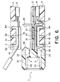
- Fig. 6 is a vertical sectional view of a cable connector according to a second embodiment of the present invention;
- Fig. 7 is a vertical sectional view of a cable connector according to a third embodiment of a present invention;
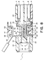
- Fig. 8 is a vertical sectional view of a cable connector according to a fourth embodiment of the present invention;
- Fig. 9 is a vertical sectional view of a cable connector according to a fifth embodiment of the present invention;
- Fig. 10 is a vertical sectional view of a cable connector according to a sixth embodiment of the present invention;
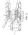
- Fig. 11 is a vertical sectional view of a cable connector according to a seventh embodiment of the present invention;
- Fig. 12 is a vertical sectional view of a cable connector according to an eighth embodiment of the present invention;
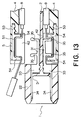
- Fig. 13 is a vertical sectional view of a cable connector according to a ninth embodiment of the present invention; and
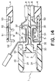
- Fig. 14 is a vertical sectional view of a cable connector according to a tenth embodiment of the present invention.
-
- With reference to Figs. 1, 2, 3, 4A, 4B, and 4C, description will be made as regards a cable connector according to a first embodiment of the present invention.
- The cable connector is designated by a
reference numeral 1 and comprises abase insulator 2, a plurality ofbase contacts 3, twocover insulators 4, and a plurality ofsupport contacts 5. Thecable connector 1 is for connecting a flattenedcoaxial cable 8 with a drain wire to a mating connector (not shown) as an object of connection. - Referring to Fig. 5 shortly, the flattened
coaxial cable 8 comprises a plurality ofcoaxial cables 81 with the drain wire and an UV-setting resin orfilm 82 coupling thecoaxial cables 81. Moreover, each of thecoaxial cables 81 comprises asignal wire 81a, adielectric member 81b surrounding thesignal wire 81a, adrain wire 81c extending in parallel to thesignal wire 81a, ashield 81d, and asheath 81e. Theshield 81d covers thesignal wire 81a, thedielectric member 81b, and thedrain wire 81c. Thesheath 81e accommodates thesignal wire 81a, thedielectric member 81b, thedrain wire 81c, and theshield 81d. In case of the flattenedcoaxial cable 8, thesignal wire 81a and thedrain wire 81c will collectively be called as a core wire. - Returning to Figs. 1-4C, the
base insulator 2 has a flat-plate portion 21, afitting portion 22, andprotrusions 23 as a first clamp portion. The flat-plate portion 21 has a plate-like shape and adapted to receive and support thecoaxial cable 8 in its thickness direction. The flat-plate portion 21 is provided with astopper 21a for preventing the displacement of thebase contact 3 in the direction perpendicular to the drawing sheet of Fig. 1. Thefitting portion 22 is a portion to be engaged with the mating connector and is formed integral with one end of the flat-plate portion 21. Theprotrusions 23 are formed at the other end of the flat-plate portion 21 to integrally protrude from the upper and the lower surfaces thereof, respectively. Theprotrusions 23 serve to clamp thecoaxial cable 8 in a predetermined direction A1. - Each of the
base contacts 3 has a clampingportion 31 for clamping the core wire of thecoaxial cable 8, a corewire contacting portion 32 formed at one end of the clampingportion 31 to be contacted with the core wire, a press-fittedportion 33 formed at one end of the corewire contacting portion 32 to be press-fitted into thefitting portion 22, a matingconnector contacting portion 34 formed at one end of the press-fit portion 33 to be brought into contact with the mating connector and a base-side elastic contactingspring 35 formed at the other end of the clampingportion 31 to press the core wire against thesupport contact 5. Thebase contacts 3 are press-fitted into thefitting portion 22 at a predetermined pitch on the upper and the lower surfaces of the flat-plate portion 21. - Each of the
cover insulators 4 has a generally flat plate-shape and comprises a plurality ofcontact holding portions 41 formed at its one end to be faced to thebase contacts 3 in the predetermined direction A1,partition walls 42 formed on both sides of eachcontact holding portions 41 to position the core wire with respect to thesupport contact 5 and thebase contact 3, and aclamp valley 43 as a second clamping portion which is formed on the side of thebase insulator 2 at the other end of thecover insulator 4 to clamp, in the predetermined direction A1, thecoaxial cable 8 at its end surface in its thickness direction in cooperation with theprotrusions 23. Thepartition wall 42 is provided with arecess 42a to avoid contact with thestopper 21a formed on thebase insulator 2. The twocover insulators 4 are abutted or assembled to thebase insulator 2 to sandwich thebase insulator 2 therebetween in the above-mentioned predetermined direction a. In this state, the cover insulators are coupled to each other by the use ofscrews 44 to be fixed to thebase insulator 2 as shown in Fig. 4B. - Each of the
support contacts 5 is generally E-shaped and comprises a clampingportion 51 for clamping the core wire of thecoaxial cable 8 in cooperation with the clampingportion 31 of thebase contact 3 where thecover insulators 4 are abutted to thebase insulator 2, a support-side elastic contactingspring 52 formed at one end of the clampingportion 51 to press the core wire against the corewire contacting portion 32 of thebase contact 3, a press-fit portion 53 formed at the center portion of the clampingportion 51 to be press-fitted into thecontact holding portion 41 of thecover insulator 4, and a receivingportion 54 formed at the other end of the clampingportion 51 to be faced to the base-side elastic contactingspring 35 of thebase contact 3 and to receive the core wire pressed by the base side elastic contactingspring 35. Each of thesupport contacts 5 is arranged between the partition wails 42 by press-fitting the press-fit portion 53 into thecontact holding portion 41 of thecover insulator 4. Next, description will be made about a wire connection method for connecting the flattenedcoaxial cable 8 to thecable connector 1. - At first, the UV-setting
resin 82, thesheath 81e, theshield 81d, and thedielectric member 81b are cut off in the vicinity of a terminal end of thecoaxial cable 8. A portion between the cut-off portion and the terminal end is displaced toward the terminal end of the cable as far as it is not released from thesignal wire 81a and thedrain wire 81c. Thus, a part of each of thesignal wire 81a and thedrain wire 81c is half-stripped as shown in Figs. 5A and 5B. - In this state, the
coaxial cable 8 is then placed on thecover insulator 4, as shown above thebase insulator 2 illustrated in Figs. 1 to 3. At this time, each of thesignal wire 81a and thedrain wire 81c of thecoaxial cable 8 is arranged between thepartition walls 42 to bring each of thesignal wire 81a and thedrain wire 81c into contact with thesupport contact 5. - Next, the
cover insulator 4 with thecoaxial cable 8 arranged thereon is abutted to thebase insulator 2 together with thecoaxial cable 8 in the predetermined direction A1, as shown below thebase insulator 2 illustrated in Figs. 1 to 3. As a result, each of thesignal wire 81a and thedrain wire 81 of thecoaxial cable 8 is clamped by thebase contact 3 and thesupport contact 5 so that each of thesignal wire 81a and thedrain wire 81c is connected to thebase contact 3. Simultaneously, thecoaxial cable 8 is clamped by theprotrusions 23 and theclamp valley 43 in the predetermined direction A1 at an unexposed portion where thesignal wire 81a and thedrain wire 81c are not exposed. In this state, each of thesignal wire 81a and thedrain wire 81c is electrically connected to thebase contact 3 at least at two points, namely points P1 and P2, by the base side elastic contactingspring 35 and the support side elastic contactingspring 52. Then, as shown in Figs. 4A-4C, thecover insulators 4 abutted to thebase insulator 2 from the upper and the lower sides are coupled to each other by the use of thescrews 44 to fix thecover insulators 4 to thebase insulator 2. - Finally, excessive parts of the
signal wire 81a and thedrain wire 81c are cut off and removed together with the UV-settingresin 82, thesheath 81e, theshield 81d, and thedielectric member 81b which have been cut off at one end of thecoaxial cable 8. Thecable connector 1 is completed through the above-described steps. - With reference to Fig. 6, the description will be made as regards a cable connector according to a second embodiment of the present invention. Similar parts are designated by like reference numerals. In the
cable connector 1 of Fig. 6, the base-side elastic contactingsprings 35 are formed integral with both ends of the clampingportion 31 of thebase contact 3. The receivingportions 54 are formed integral with both ends of thesupport contact 5. The base-side elastic contactingsprings 35 of thebase contact 3 clamp the core wire of thecoaxial cable 8 in cooperation with the receivingportions 54 of thesupport contact 5. - With reference to Fig. 7, the description will be made as regards a cable connector according to a third embodiment of the present invention. Similar parts are designated by like reference numerals. In the
cable connector 1 of Fig. 7, the corewire contacting portion 32 is formed integral with the center of the clampingportion 31 of thebase contact 3. A pair of the support-side elastic contactingsprings 52 are formed integral with the clampingportion 51 of thesupport contact 5. The press-fit portion 53 is formed integral with one end of the clampingportion 51. The above-mentioned pair of support-side elastic contactingsprings 52 clamp the core wire of thecoaxial cable 8 and press the core wire against the corewire contacting portion 32. - With reference to Fig. 8, the description will be made as regards a cable connector according to a fourth embodiment of the present invention. Similar parts are designated by like reference numerals. In the
cable connector 1 of Fig. 8, thecover insulator 4 comprises acover insulator body 40 having the clamp valley (not shown) and thecontact holding portion 41 which is a component separate from thecover insulator body 40, which has thepartition wall 42, and which is removable from the cover insulatormain body 40. In thecable connector 1, thebase insulator 2 is also provided with apartition wall 24. The fourth embodiment has a structure substantially same to that of the first embodiment if thecontact holding portion 41 is attached to thecover insulator body 40. However, in the fourth embodiment, it is possible to perform connection of the core wire as a last step by attaching thecontact holding portion 41 to thecover insulator body 40 after thecover insulator body 40 is fixed to thebase insulator 2. - With reference to Fig. 9, the description will be made as regards a cable connector according to a fifth embodiment of the present invention. Similar parts are designated by like reference numerals. In the
cable connector 1 of Fig. 9, the corewire contacting portions 32 are formed integral with both ends of the clampingportion 31 of thebase contact 3. The support-side elastic contactingsprings 52 are formed integral with both ends of the clampingportion 51 of thesupport contact 5. The most characteristic part of this embodiment is thecontact holding portion 41 of thecover insulator 4. Thecontact holding portion 41 is adapted to press the core wire of thecoaxial cable 8 against thebase contact 3 in cooperation with thesupport contact 5. - With reference to Fig. 10, the description wilt be made as regards a cable connector according to a sixth embodiment of the present invention. Similar parts are designated by like reference numerals. The
cable connector 1 of Fig. 10 is generally similar in structure to the cable connector of Fig. 9. However, thecontact holding portion 41 of thecover insulator 4 is not adapted to press the core wire of thecoaxial cable 8 against thebase contact 3. Thesupport contact 5 is press-fitted into thecontact holding portion 41 so that the clampingportion 51 is located at one side of thecontact holding portion 41 faced tobase insulator 2. - With reference to Fig. 11, the description will be made as regards a cable connector according to a seventh embodiment of the present invention. Similar parts are designated by like reference numerals. In the
cable connector 1 of Fig. 11, the corewire contacting portion 32 is formed integral with one end of the clampingportion 31 of thebase contact 3 while nothing is provided at the other end of the clampingportion 31. The first support-side elastic contactingspring 52 is formed at one end of the clampingportion 51 of thesupport contact 5 while the second support-side elastic contacting spring 52' is formed at the other end of the clampingportion 51 to be aligned therewith. - With reference to Fig. 12, the description will be made as regards a cable connector according to an eighth embodiment of the present invention. Similar parts are designated by like reference numerals. In the
cable connector 1 of Fig. 12, the corewire contacting portions 32 are formed integral with both ends of the clampingportion 31 of thebase contact 3. The support-side elastic contactingsprings 52 are formed integral with one end and at the center of the clampingportion 51 of thesupport contact 5. The press-fit portion 53 is formed integral with the other end of the clampingportion 51 to be aligned with the clampingportion 51. - With reference to Fig. 13, the description will be made as regards a cable connector according to a ninth embodiment of the present invention. Similar parts are designated by like reference numerals. The
cable connector 1 of Fig. 13 has a structure such that the relationship between the corewire contacting portion 32 and the support-side elastic contactingspring 52 is reverse to that of the cable connector of Fig. 12. Specifically, the base-side elastic contactingsprings 35 are formed integral with one end and with the center of the clampingportion 31 of thebase contact 3, the receivingportions 54 being formed at both ends of the clampingportion 51 of thesupport contact 5. - With reference to Fig. 14, the description will be made as regards a cable connector according to a tenth embodiment of the present invention. Similar parts are designated by like reference numerals. The
cable connector 1 of Fig. 14 is substantially similar in structure to the cable connector of Fig. 12 except that thecover insulator 4 is not provided with the partition wall. Instead, thebase insulator 2 is provided with thepartition wall 24. In the cable connector of Fig. 14, thecoaxial cable 82 is at first placed on thebase insulator 2. Then, thecover insulator 4 is abutted and fixed to thebase insulator 2. - While the present invention has thus far been described in connection with a few embodiments thereof, it will readily be possible for those skilled in the art to put this invention into practice in various other manners. For example, the cover insulator may be fixed to only one surface of the base insulator. The partition wall may be formed in each of the cover insulator and the base insulator. Alternatively, the partition wall may be formed only on the base insulator. The support contact may be connected to the connection object. Further alternatively, both of the base contact and the support contact may be connected to the connection object. The cover insulator may be fixed to the base insulator, for example, by the use of an engaging mechanism such as engaging claws. Moreover, the cable connector can be applied not only to the flattened coaxial cable with a drain wire but also to various common cables.
Claims (10)
- A cable connector (1) for use in connecting a cable (8) having a core wire (81a, 81c), said cable connector (1) comprising a base insulator (2), a base contact (3) coupled to said base insulator (2), and a pressing device (35) for pressing said core wire (81a, 81c) against said base contact (3) in a predetermined direction (A1) intersecting said core wire (81a, 81c), said pressing device comprising: a cover insulator (4) coupled to said base insulator (2) and movable in said predetermined direction; a partition wall (42) formed integral with said cover insulator (4) for positioning said core wire (81a, 81c) to make said core wire (81a, 81c) face said base contact (3) in said predetermined direction; and a support contact (5) coupled to said cover insulator (4) and cooperated with said base contact (3) for clamping said core wire (81a, 81c) therebetween with movement of said cover insulator (4) towards said base insulator (2).
- A cable connector as claimed in claim 1, wherein at least one of said base contact (3) and said support contact (5) has an elastic contacting spring portion (35, 52) for electrically connecting said core wire (81a, 81c) to said at least one.
- A cable connector as claimed in claim 1 or 2, wherein said base insulator (2) has a stopper (21a) for preventing said base contact (3) from being displaced in a direction which is perpendicular to said predetermined direction and said core wire (81a, 81c).
- A cable connector as claimed in one of claims 1 to 3, further comprising at least one screw (44) and/or an engaging mechanism for fixing said cover insulator (4) to said base insulator (2).
- A cable connector as claimed in one of claims 1 to 4, wherein said base insulator (2) has a first clamping portion (23), said cover insulator (4) having a second clamping portion (43) cooperated with said first clamping portion (23) for clamping said cable (8) in said predetermined direction (A1).
- A cable connection method for connecting a cable (8) to the cable connector (1) according to claim 1, said cable having a core wire (81a, 81c), said method comprising the steps of: exposing, as a exposed part, a part of said core wire (81s, 81c) by half stripping an end of said cable (8); disposing said cable(8) on said cover insulator (4) so that said exposed part is brought into contact with said support contact (5): and moving said cover insulator (4) together with said exposed part towards said vase insulator (2) in said predetermined direction (A1) to clamp said exposed part between said base contact (3) and said support contact (5).
- A method as claimed in claim 6, further comprising the step of fixing said cover insulator (4) to said base insulator (2) in a condition where said cover insulator (4) is moved towards said base insulator (2).
- A method as claimed in claim 6 or 7, further comprising the step of cutting the end of said cable (8) after the moving step.
- A method as claimed in claim 7, wherein at least one of said base contact (3) and said support contact (5) has an elastic contacting spring portion (35, 52) for electrically connecting said core wire (81a, 81c) to said at least one.
- A method as claimed in claim 7, wherein said base insulator (2) has a stopper (21a) for preventing said base contact (3) from being displaced in a direction which is perpendicular to said predetermined direction (A1) and said core wire (81a, 81c) and/or a first clamping portion (23), said cover insulator (4) having a second clamping portion (43) cooperated with said first clamping portion (23) for clamping said cable (8) in said predetermined direction (A1).
Applications Claiming Priority (2)
| Application Number | Priority Date | Filing Date | Title |
|---|---|---|---|
| JP08575299A JP3265424B2 (en) | 1999-03-29 | 1999-03-29 | Cable connector and its connection method |
| JP8575299 | 1999-03-29 |
Publications (2)
| Publication Number | Publication Date |
|---|---|
| EP1041682A1 true EP1041682A1 (en) | 2000-10-04 |
| EP1041682B1 EP1041682B1 (en) | 2003-07-09 |
Family
ID=13867601
Family Applications (1)
| Application Number | Title | Priority Date | Filing Date |
|---|---|---|---|
| EP00106708A Expired - Lifetime EP1041682B1 (en) | 1999-03-29 | 2000-03-29 | Cable connector in which two contacts clamp a wire core of a cable therebetween |
Country Status (6)
| Country | Link |
|---|---|
| US (2) | US6217344B1 (en) |
| EP (1) | EP1041682B1 (en) |
| JP (1) | JP3265424B2 (en) |
| AU (1) | AU776760B2 (en) |
| CA (1) | CA2302928C (en) |
| DE (1) | DE60003742T2 (en) |
Cited By (9)
| Publication number | Priority date | Publication date | Assignee | Title |
|---|---|---|---|---|
| WO2003032444A1 (en) * | 2000-08-22 | 2003-04-17 | Japan Aviation Electronics Industry, Limited | Connector for flat cable |
| WO2003032443A1 (en) * | 2000-08-28 | 2003-04-17 | Japan Aviation Electronics Industry, Limited | Cable connector |
| WO2004109862A1 (en) * | 2003-05-30 | 2004-12-16 | 3M Innovative Properties Company | Wire connection structure and connector |
| EP1227551A3 (en) * | 2001-01-22 | 2005-06-22 | Fci | Plug connector with strain relief clamp |
| US7070444B2 (en) | 2000-08-28 | 2006-07-04 | Japan Aviation Electronics Industry, Limited | Cable connector |
| US7114988B2 (en) | 2000-08-22 | 2006-10-03 | Japan Aviation Electronics Industry, Limited | Connector for connecting a flat cable and for securely retaining the same |
| US7201606B2 (en) | 2003-05-30 | 2007-04-10 | 3M Innovative Properties Company | Wire connection structure and connector |
| WO2008084275A3 (en) * | 2006-12-29 | 2008-11-20 | Framatome Connectors Int | Improved solderless wire termination assembly |
| EP2445059A1 (en) * | 2008-09-04 | 2012-04-25 | Sumitomo Wiring Systems, Ltd. | A connector cover, a connector and a method of assembling it |
Families Citing this family (12)
| Publication number | Priority date | Publication date | Assignee | Title |
|---|---|---|---|---|
| JP2005129255A (en) * | 2003-10-21 | 2005-05-19 | Three M Innovative Properties Co | Connector and connector system |
| JP2005294106A (en) * | 2004-04-01 | 2005-10-20 | Three M Innovative Properties Co | Connector and its wire connection method |
| JP2006049211A (en) * | 2004-08-06 | 2006-02-16 | Three M Innovative Properties Co | Coaxial cable grounding structure as well as connector and its wire connection method |
| JP2008077952A (en) * | 2006-09-21 | 2008-04-03 | Japan Aviation Electronics Industry Ltd | connector |
| US8123001B1 (en) | 2008-03-18 | 2012-02-28 | Paul Kristen, Inc. | Modular platform/ scaffolding |
| US7530839B1 (en) * | 2008-04-15 | 2009-05-12 | Jess-Link Products Co., Ltd. | Electrical connector |
| JP5087487B2 (en) * | 2008-07-22 | 2012-12-05 | 矢崎総業株式会社 | connector |
| JP5289154B2 (en) * | 2009-04-15 | 2013-09-11 | 矢崎総業株式会社 | connector |
| JP2013235808A (en) * | 2012-04-12 | 2013-11-21 | Panasonic Corp | Connector, housing with lead wire used in the connector, housing, and contact |
| US9543729B2 (en) | 2013-08-19 | 2017-01-10 | Sullstar Technologies, Inc | Electrical connector with removable external load bar, and method of its use |
| JP6762329B2 (en) * | 2018-02-15 | 2020-09-30 | 株式会社オートネットワーク技術研究所 | connector |
| US11489279B2 (en) * | 2020-06-24 | 2022-11-01 | Te Connectivity Solutions Gmbh | Connector for a flat flexible cable |
Citations (3)
| Publication number | Priority date | Publication date | Assignee | Title |
|---|---|---|---|---|
| EP0018160A1 (en) * | 1979-04-11 | 1980-10-29 | Amp Incorporated | Electrical connector for terminating flat, multi-conductor electrical cable |
| EP0147080A2 (en) * | 1983-12-27 | 1985-07-03 | Amp Incorporated | Ribbon coax cable connector |
| JPH10255921A (en) * | 1997-03-06 | 1998-09-25 | Aipetsukusu:Kk | connector |
Family Cites Families (13)
| Publication number | Priority date | Publication date | Assignee | Title |
|---|---|---|---|---|
| US3696319A (en) * | 1970-08-20 | 1972-10-03 | Berg Electronics Inc | Flat conductor cable connector |
| US4181384A (en) * | 1978-02-06 | 1980-01-01 | Amp Incorporated | Flat cable connector having wire deployment means |
| US4260209A (en) * | 1978-09-05 | 1981-04-07 | Amp Incorporated | Transmission cable connector |
| US4408823A (en) * | 1981-04-10 | 1983-10-11 | Amp Incorporated | Multi-piece connector and cover means |
| US4693539A (en) * | 1983-12-27 | 1987-09-15 | Amp Incorporated | Ribbon coax cable connector |
| JPH021818Y2 (en) * | 1985-11-05 | 1990-01-17 | ||
| US5231759A (en) * | 1990-03-30 | 1993-08-03 | Amp Incorporated | Method of terminating a cable to a connector |
| JPH086387Y2 (en) * | 1991-03-08 | 1996-02-21 | ヒロセ電機株式会社 | Connector for coaxial ribbon cable |
| JPH05101853A (en) | 1991-10-08 | 1993-04-23 | Kel Corp | Electrical connector |
| US5601447A (en) * | 1995-06-28 | 1997-02-11 | Reed; Carl G. | Patch cord assembly |
| JP4152019B2 (en) | 1998-09-30 | 2008-09-17 | 日本圧着端子製造株式会社 | Multipole coaxial connector |
| JP2000150030A (en) * | 1998-11-17 | 2000-05-30 | Japan Aviation Electronics Industry Ltd | Cable connector and its connection method |
| JP2000215938A (en) | 1999-01-20 | 2000-08-04 | Sumitomo Wiring Syst Ltd | Terminal device of flat cable |
-
1999
- 1999-03-29 JP JP08575299A patent/JP3265424B2/en not_active Expired - Fee Related
-
2000
- 2000-03-27 US US09/536,209 patent/US6217344B1/en not_active Expired - Fee Related
- 2000-03-27 AU AU22593/00A patent/AU776760B2/en not_active Ceased
- 2000-03-29 EP EP00106708A patent/EP1041682B1/en not_active Expired - Lifetime
- 2000-03-29 DE DE60003742T patent/DE60003742T2/en not_active Expired - Fee Related
- 2000-03-29 CA CA002302928A patent/CA2302928C/en not_active Expired - Fee Related
-
2001
- 2001-02-22 US US09/791,016 patent/US6813830B2/en not_active Expired - Fee Related
Patent Citations (3)
| Publication number | Priority date | Publication date | Assignee | Title |
|---|---|---|---|---|
| EP0018160A1 (en) * | 1979-04-11 | 1980-10-29 | Amp Incorporated | Electrical connector for terminating flat, multi-conductor electrical cable |
| EP0147080A2 (en) * | 1983-12-27 | 1985-07-03 | Amp Incorporated | Ribbon coax cable connector |
| JPH10255921A (en) * | 1997-03-06 | 1998-09-25 | Aipetsukusu:Kk | connector |
Non-Patent Citations (1)
| Title |
|---|
| PATENT ABSTRACTS OF JAPAN vol. 1998, no. 14 31 December 1998 (1998-12-31) * |
Cited By (12)
| Publication number | Priority date | Publication date | Assignee | Title |
|---|---|---|---|---|
| WO2003032444A1 (en) * | 2000-08-22 | 2003-04-17 | Japan Aviation Electronics Industry, Limited | Connector for flat cable |
| US7114988B2 (en) | 2000-08-22 | 2006-10-03 | Japan Aviation Electronics Industry, Limited | Connector for connecting a flat cable and for securely retaining the same |
| US7267573B2 (en) | 2000-08-22 | 2007-09-11 | Japan Aviation Electronics Industry, Limited | Connector for flat cable |
| WO2003032443A1 (en) * | 2000-08-28 | 2003-04-17 | Japan Aviation Electronics Industry, Limited | Cable connector |
| US7070444B2 (en) | 2000-08-28 | 2006-07-04 | Japan Aviation Electronics Industry, Limited | Cable connector |
| EP1227551A3 (en) * | 2001-01-22 | 2005-06-22 | Fci | Plug connector with strain relief clamp |
| EP1437799A4 (en) * | 2001-09-26 | 2007-06-13 | Japan Aviation Electron | CONNECTORS |
| AU2001292249B2 (en) * | 2001-09-26 | 2008-02-07 | Japan Aviation Electronics Industry, Limited | Cable connector |
| WO2004109862A1 (en) * | 2003-05-30 | 2004-12-16 | 3M Innovative Properties Company | Wire connection structure and connector |
| US7201606B2 (en) | 2003-05-30 | 2007-04-10 | 3M Innovative Properties Company | Wire connection structure and connector |
| WO2008084275A3 (en) * | 2006-12-29 | 2008-11-20 | Framatome Connectors Int | Improved solderless wire termination assembly |
| EP2445059A1 (en) * | 2008-09-04 | 2012-04-25 | Sumitomo Wiring Systems, Ltd. | A connector cover, a connector and a method of assembling it |
Also Published As
| Publication number | Publication date |
|---|---|
| US6813830B2 (en) | 2004-11-09 |
| US20010005651A1 (en) | 2001-06-28 |
| AU2259300A (en) | 2000-10-05 |
| DE60003742T2 (en) | 2004-05-27 |
| DE60003742D1 (en) | 2003-08-14 |
| JP2000277190A (en) | 2000-10-06 |
| AU776760B2 (en) | 2004-09-23 |
| JP3265424B2 (en) | 2002-03-11 |
| CA2302928A1 (en) | 2000-09-29 |
| US6217344B1 (en) | 2001-04-17 |
| EP1041682B1 (en) | 2003-07-09 |
| CA2302928C (en) | 2003-11-18 |
Similar Documents
| Publication | Publication Date | Title |
|---|---|---|
| CA2302928C (en) | Cable connector in which two contacts clamp a wire core of a cable therebetween | |
| US7377803B2 (en) | Connector and connector system | |
| US20230084529A1 (en) | Connector | |
| US11152718B2 (en) | Electrical cable including terminal having pressing portion that presses holding portion | |
| JPH0622927Y2 (en) | Pressure terminal | |
| JP3019188U (en) | Electrical connector for high density ribbon cable | |
| US6254430B1 (en) | Coaxial connector | |
| EP0490542B1 (en) | Strain relief for insulation displacement contact | |
| CN1069450C (en) | Connector for electric cable | |
| JPH0626152B2 (en) | Shielded electrical plug assembly | |
| JP3262198B2 (en) | connector | |
| US20020127904A1 (en) | Relay connector | |
| JPH087968A (en) | Connector and assembly method thereof | |
| US6149460A (en) | RF plug connection system and method for assembling the RF plug connection system | |
| EP0145315A2 (en) | Connecting device for closely spaced conductors and electrical contact terminal therefor | |
| US4898545A (en) | Thin-type coaxial connector and receptacle for mating with the coaxial connectors | |
| JPH0145714B2 (en) | ||
| EP1199773B1 (en) | Electrical connector and terminal | |
| CN1125509C (en) | Miniature electric connector and making method thereof | |
| JP3300298B2 (en) | connector | |
| JP2920819B2 (en) | Cable connector | |
| JPH0419679B2 (en) | ||
| JP3269809B2 (en) | IDC electrical connector | |
| JP2000306622A (en) | connector | |
| JP3282716B2 (en) | Method and apparatus for crimping wire |
Legal Events
| Date | Code | Title | Description |
|---|---|---|---|
| PUAI | Public reference made under article 153(3) epc to a published international application that has entered the european phase |
Free format text: ORIGINAL CODE: 0009012 |
|
| AK | Designated contracting states |
Kind code of ref document: A1 Designated state(s): DE FR NL |
|
| AX | Request for extension of the european patent |
Free format text: AL;LT;LV;MK;RO;SI |
|
| 17P | Request for examination filed |
Effective date: 20001211 |
|
| 17Q | First examination report despatched |
Effective date: 20010213 |
|
| AKX | Designation fees paid |
Free format text: DE FR NL |
|
| GRAG | Despatch of communication of intention to grant |
Free format text: ORIGINAL CODE: EPIDOS AGRA |
|
| GRAG | Despatch of communication of intention to grant |
Free format text: ORIGINAL CODE: EPIDOS AGRA |
|
| GRAG | Despatch of communication of intention to grant |
Free format text: ORIGINAL CODE: EPIDOS AGRA |
|
| GRAH | Despatch of communication of intention to grant a patent |
Free format text: ORIGINAL CODE: EPIDOS IGRA |
|
| RIN1 | Information on inventor provided before grant (corrected) |
Inventor name: KAMIYAMANE, SHIN, C/O NEC CORPORATION Inventor name: ISHIDA, HISASHI, C/O NEC CORPORATION Inventor name: HASHIGUCHI, OSAMU, C/O JAPAN AVIATION ELECTRONICS Inventor name: SAITO, KAZUKI, C/O JAPAN AVIATION ELECTRONICS IND. |
|
| GRAH | Despatch of communication of intention to grant a patent |
Free format text: ORIGINAL CODE: EPIDOS IGRA |
|
| GRAA | (expected) grant |
Free format text: ORIGINAL CODE: 0009210 |
|
| AK | Designated contracting states |
Designated state(s): DE FR NL |
|
| REF | Corresponds to: |
Ref document number: 60003742 Country of ref document: DE Date of ref document: 20030814 Kind code of ref document: P |
|
| ET | Fr: translation filed | ||
| PLBE | No opposition filed within time limit |
Free format text: ORIGINAL CODE: 0009261 |
|
| STAA | Information on the status of an ep patent application or granted ep patent |
Free format text: STATUS: NO OPPOSITION FILED WITHIN TIME LIMIT |
|
| 26N | No opposition filed |
Effective date: 20040414 |
|
| PGFP | Annual fee paid to national office [announced via postgrant information from national office to epo] |
Ref country code: FR Payment date: 20060327 Year of fee payment: 7 |
|
| PGFP | Annual fee paid to national office [announced via postgrant information from national office to epo] |
Ref country code: NL Payment date: 20060331 Year of fee payment: 7 Ref country code: DE Payment date: 20060331 Year of fee payment: 7 |
|
| NLV4 | Nl: lapsed or anulled due to non-payment of the annual fee |
Effective date: 20071001 |
|
| REG | Reference to a national code |
Ref country code: FR Ref legal event code: ST Effective date: 20071130 |
|
| PG25 | Lapsed in a contracting state [announced via postgrant information from national office to epo] |
Ref country code: NL Free format text: LAPSE BECAUSE OF NON-PAYMENT OF DUE FEES Effective date: 20071001 Ref country code: DE Free format text: LAPSE BECAUSE OF NON-PAYMENT OF DUE FEES Effective date: 20071002 |
|
| PG25 | Lapsed in a contracting state [announced via postgrant information from national office to epo] |
Ref country code: FR Free format text: LAPSE BECAUSE OF NON-PAYMENT OF DUE FEES Effective date: 20070402 |