EP1003245A1 - Cable connector capable of reliably connecting a cable and a method of connecting the cable to the cable connector - Google Patents
Cable connector capable of reliably connecting a cable and a method of connecting the cable to the cable connector Download PDFInfo
- Publication number
- EP1003245A1 EP1003245A1 EP99122755A EP99122755A EP1003245A1 EP 1003245 A1 EP1003245 A1 EP 1003245A1 EP 99122755 A EP99122755 A EP 99122755A EP 99122755 A EP99122755 A EP 99122755A EP 1003245 A1 EP1003245 A1 EP 1003245A1
- Authority
- EP
- European Patent Office
- Prior art keywords
- cable
- contacts
- base
- core wires
- cable connector
- Prior art date
- Legal status (The legal status is an assumption and is not a legal conclusion. Google has not performed a legal analysis and makes no representation as to the accuracy of the status listed.)
- Granted
Links
Images


Classifications
-
- H—ELECTRICITY
- H01—ELECTRIC ELEMENTS
- H01R—ELECTRICALLY-CONDUCTIVE CONNECTIONS; STRUCTURAL ASSOCIATIONS OF A PLURALITY OF MUTUALLY-INSULATED ELECTRICAL CONNECTING ELEMENTS; COUPLING DEVICES; CURRENT COLLECTORS
- H01R12/00—Structural associations of a plurality of mutually-insulated electrical connecting elements, specially adapted for printed circuits, e.g. printed circuit boards [PCB], flat or ribbon cables, or like generally planar structures, e.g. terminal strips, terminal blocks; Coupling devices specially adapted for printed circuits, flat or ribbon cables, or like generally planar structures; Terminals specially adapted for contact with, or insertion into, printed circuits, flat or ribbon cables, or like generally planar structures
- H01R12/70—Coupling devices
- H01R12/77—Coupling devices for flexible printed circuits, flat or ribbon cables or like structures
- H01R12/771—Details
- H01R12/774—Retainers
-
- H—ELECTRICITY
- H01—ELECTRIC ELEMENTS
- H01R—ELECTRICALLY-CONDUCTIVE CONNECTIONS; STRUCTURAL ASSOCIATIONS OF A PLURALITY OF MUTUALLY-INSULATED ELECTRICAL CONNECTING ELEMENTS; COUPLING DEVICES; CURRENT COLLECTORS
- H01R12/00—Structural associations of a plurality of mutually-insulated electrical connecting elements, specially adapted for printed circuits, e.g. printed circuit boards [PCB], flat or ribbon cables, or like generally planar structures, e.g. terminal strips, terminal blocks; Coupling devices specially adapted for printed circuits, flat or ribbon cables, or like generally planar structures; Terminals specially adapted for contact with, or insertion into, printed circuits, flat or ribbon cables, or like generally planar structures
- H01R12/70—Coupling devices
- H01R12/82—Coupling devices connected with low or zero insertion force
- H01R12/85—Coupling devices connected with low or zero insertion force contact pressure producing means, contacts activated after insertion of printed circuits or like structures
-
- H—ELECTRICITY
- H01—ELECTRIC ELEMENTS
- H01R—ELECTRICALLY-CONDUCTIVE CONNECTIONS; STRUCTURAL ASSOCIATIONS OF A PLURALITY OF MUTUALLY-INSULATED ELECTRICAL CONNECTING ELEMENTS; COUPLING DEVICES; CURRENT COLLECTORS
- H01R12/00—Structural associations of a plurality of mutually-insulated electrical connecting elements, specially adapted for printed circuits, e.g. printed circuit boards [PCB], flat or ribbon cables, or like generally planar structures, e.g. terminal strips, terminal blocks; Coupling devices specially adapted for printed circuits, flat or ribbon cables, or like generally planar structures; Terminals specially adapted for contact with, or insertion into, printed circuits, flat or ribbon cables, or like generally planar structures
- H01R12/50—Fixed connections
- H01R12/59—Fixed connections for flexible printed circuits, flat or ribbon cables or like structures
- H01R12/594—Fixed connections for flexible printed circuits, flat or ribbon cables or like structures for shielded flat cable
- H01R12/596—Connection of the shield to an additional grounding conductor, e.g. drain wire
Definitions
- the present invention relates to a cable connector for use in connecting a cable and to a method of connecting the cable to the cable connector.
- a cable connector of Fig. 1A comprises a contact housing 21 of synthetic resin, a cable housing 22 of synthetic resin, and a cover member 23 of synthetic resin.
- a flat cable 25 has core wires 26 and is previously passed through a slit 24 of the cover member 23.
- the cable housing 22 holds exposed tips of the core wires 26 and is inserted into a rear inner space 37 of the contact housing 21. Then, by engaging the recesses 29 of respective engaging strips 28 at both sides of the cover member 23 with respective protrusions 30 at both sides of the contact housing 21, the cable housing 22 and the contact housing 21 are fitted together as shown in Fig. 1B.
- the core wires 26 are extended along the cable housing 22.
- a plurality of contact members 31 are arranged on the contact housing 21.
- Each of the contact members 31 is made of metal to have a U-shaped portion 31a.
- the distance between an upper portion and a lower portion of each of the core wires 26 is made slightly larger than the distance between two tips of the U-shaped lead 31A of each of the contact members 31.
- a wire-cutting edge (not shown) is inserted through each of holes 38 of the contact housing 21 to cut off the tips of the core wires 26.
- the core wires 26 are pressed against the cable housing 22 the contact members 31, respectively.
- this conventional structure and method cannot cope with the cable connectors of today where the intervals between contacts are becoming rapidly smaller.
- These small pitch contacts require small diameter core wires which are sometimes as small as 0.1 mm. It is difficult to press such a thin wires with contacts against the contact housing made of synthetic resin, and the connection between the core wires and the contacts tends to lack in reliability and stability.
- a cable connector for connecting a cable having a plurality of core wires.
- the cable connector comprises a cover member for covering said cable, a plurality of support contacts held by said cover member and extending in a first direction, said core wires being in close contact with said support contacts, respectively, a base member removably coupled to said cover member, and a plurality of base contacts held by said base member and clamping said core wires onto said support contacts, respectively, in a second direction perpendicular to said first direction.
- each of said support contact has electrical conductivity, each of said base contacts having electrical conductivity and adapted to be connected to a mating connector.
- each of said base contacts has a pair of leads spaced to each other in said second direction, each of said support contacts being inserted between said leads of each of said base contact, each of said core wires extending between each of said leads of each of said base contact and each of said support contacts.
- each of said core wires is folded over each of said support contacts, each of said base contacts having a U-shaped portion which is fitted over each of said core wires to come in contact with each of said core wire at two points.
- said cover member has a plurality of partition walls which are at both sides of said support contact and opposite to each other in a third direction perpendicular to said first and said second direction, each of said base contacts being inserted between said partition walls.
- said core wires have signal wires and drain wires arranged alternately.
- a method of connecting a cable, having a plurality of core wires, to the above-mentioned cable connector comprises the steps of making said cable have a half-stripped portion in which said core wires are exposed, folding said core wires over said support contacts, respectively, coupling said base member with said cover members to make said base contacts press said core wires onto said support contacts, respectively, and cutting off the tips of said core wires outside of said base members. It may be arranged that the cutting step is carried out on the way of performing the coupling step.
- a cable connector 1 is for connecting upper and lower coaxial cables 2 and comprises upper and lower cover insulators 3 clamping the coaxial cables 2, a base insulator or a base member 4 removably coupled to the cover insulators 3, a plurality of support contacts 7 held by the cover insulators 3, and a plurality of base contacts 8 held by the base insulator 4.
- the base insulator 4 and the two cover insulators 3 are fixed together with four screws 5.
- a combination of the upper and the lower cover insulators 3 is referred to as a cover member for covering the coaxial cables 2.
- Each of the support contacts 7 extends in a left and right direction or a first direction.
- the coaxial cables 2 have a plurality of core wires 2a and 2b which extend around the support contacts 7 to be in close contact with the support contacts 7, respectively.
- the base contacts 8 press the core wires 2a and 2b onto the support contacts 7 in an upper and lower direction or a second direction perpendicular to the first direction.
- Each of the upper and the lower cover insulators 3 is made of synthetic resin.
- the base insulator 4 is made of synthetic resin.
- Each of the support contacts 7 is made of metal to have electrical conductivity.
- Each of the base contacts 8 is made of metal to have electrical conductivity.
- a spacer 6 is a plate member made of rubber or other material and is inserted between upper and lower coaxial cables 2. The spacer 6 is held between recesses 3a of upper and lower cover insulators 3, thus preventing each coaxial cable 2 from escaping out of the cover insulators 3.
- Each of the cover insulators 3 incorporates the support contacts 7 onto which the core wires 2a and 2b of each coaxial cable 2 are folded over, respectively. These wires 2a and 2b may be fixed the support contacts 7 by means of welding or soldering.
- the core wires 2a and 2b will be called signal wires and drain wires, respectively.
- the base contacts 8 are incorporated in the base insulator 4.
- Each of the base contacts has U-shaped portion 8a having a pair of leads spaced to each other in the second direction. The U-shaped portion 8a clamp the signal wires 2a and the drain wires 2b as well as the support contacts 7 with strong contacting force at two contacting points.
- the cable connector 1 is connected to a mating connector 9 in the manner known in the art.
- the mating connector 9 is already mounted on a printed circuit board 11.
- the respective base contacts 8 are connected electrically with respective contacts 10 of the mating connector 9.
- the respective support contacts 7 are incorporated in the respective cover insulators 3. Also, the respective base contacts 8 are incorporated in the base insulator 4.
- the two coaxial cables 2 laid one over another are clamped between the upper and lower cover insulators 3 which are fixed at two points (located farther from the base insulator 4 with two screws 5.
- the respective coaxial cables 2 have been half-stripped beforehand in the manner known in the art. After that, the wires 2a and 2b are separated at equal intervals.
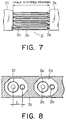
- a sheath 2c of the coaxial cable 2 is made of UV curable resin or film as shown in Fig. 8.
- the sheath 2c has multiple bores 2d at equal intervals to accommodate the signal wires 2a and the drain wires 2b therein.
- the signal wires 2a are coated with dielectric substance 2e.
- the drain wires 2b and dielectric substance 2e are coated with shields 2f.
- a structure is adopted in which the interval L between the signal wire 2a and the drain wire 2a is made larger than usual, in order to facilitate the forming operation in which the signal wires 2a and the drain wires 2b are folded over onto the support contacts 7, respectively.
- the cover insulator 3 has a plurality of partition walls 3c as shown in Figs. 8 and 9.
- the partition walls 3c are located at both sides of each of the support contacts 7 and opposite to each other in a third direction perpendicular to the first and the second direction.
- the partition walls 3c protrude higher than the signal wires 2a and the drain wires 2b in order that the wires do not leave the respective support contacts 7.
- Each of the base contacts 8 is inserted between the partition walls 3c.
- the respective signal wires 2a and the respective drain wires 2b can be connected simultaneously with the respective base contacts 8, by fitting the base insulator 4 with the two cover insulators 3.
- the cover insulators 3 are guided to a slot 4A by means of protrusions 3b which are provided at both sides of the cover insulators 3, respectively. There are little clearance between both sides of the cover insulators 3 and inside of the slot 4a of the base insulator 4, thus preventing the positional deviation in the lateral direction at the fitting.
- the respective base contacts 8 are guided into the respective intervals or channels between the partitions 3c of the cover insulators 3, causing the respective base contacts 8 to connect with the respective signal wires 2a and the respective drain wires 2b, without a pitch error.
- the signal wires 2a and the drain wires 2b are cut during the fitting operation as shown in Fig. 9.
- the respective support contacts 7 are inserted into the respective base contacts 8 to some extent, the cutting of the signal wires 2a and the drain wires 2b at the location shown by dotted lines does not cause wires to come to disorder or to escape from the cable connector 1.
- the respective support contacts 7 are inserted into the respective base contacts 8 as far as the position shown in Fig. 2.
- the signal wires 2a and the drain wires 2b do not protrude from the base insulator 4.
- the base insulator 4 and two cover insulators 3 are fixed at two points by means of two screws 5.
Abstract
Description
Claims (8)
- A cable connector (1) for connecting a cable (2) having a plurality of core wires (2a, 2b), said cable connector (1) comprising:a cover member (3) for covering said cable (2);a plurality of support contacts (7) held by said cover member (3) and extending in a first direction, said core wires (2a, 2b) being in close contact with said support contacts (7), respectively;a base member (4) removably coupled to said cover member (3); anda plurality of base contacts (8) held by said base member (4) and clamping said core wires (2a, 2b) onto said support contacts (7), respectively, in a second direction perpendicular to said first direction.
- A cable connector as claimed in claim 1, wherein each of said support contact (7) has electrical conductivity, each of said base contacts has electrical conductivity and is adapted to be connected to a mating connector (9).
- A cable connector as claimed in claim 1 or 2, wherein each of said base contacts (8) has a pair of leads spaced to each other in said second direction, each of said support contacts (7) being inserted between said leads of each of said base contact(8), each of said core wires (2a, 2b) extending between each of said leads of each of said base contact (8) and each of said support contacts (7).
- A cable connector as claimed in one of claims 1 to 3, wherein each of said core wires (2a, 2b) is folded over each of said support contacts (7), each of said base contacts (8) having a U-shaped portion (8a) which is fitted over each of said core wires (2a, 2b) to come in contact with each of said core wire (2a, 2b) at two points.
- A cable connector as claimed in one of claims 1 to 4, wherein said cover member (3) has a plurality of partition walls (3c) which are at both sides of said support contacts (7) and opposite to each other in a third direction perpendicular to said first and said second direction, each of said base contacts (8) being inserted between said partition walls (3c).
- A cable connector as claimed in one of claims 1 to 5, wherein said core wires (2a, 2b) have signal wires (2a) and drain wires (2b) arranged alternately.
- A method of connecting a cable (2), having a plurality of core wires (2a, 2b), to a cable connector (1) as claimed in claim 1, said method comprising the steps of:making said cable (2) have a half-stripped portion in which said core wires (2a, 2b) are exposed;folding said core wires (2a, 2b) over said support contacts (7), respectively;coupling said base member (4) with said cover member (3) to make said base contacts (8) press said core wires (2a, 2b) onto said support contact (7), respectively; andcutting off the tips of said core wires (2a, 2b) outside of said base members (4).
- A method as claimed in claim 7, wherein the cutting step is carried out on the way of performing the coupling step.
Applications Claiming Priority (2)
| Application Number | Priority Date | Filing Date | Title |
|---|---|---|---|
| JP32631598 | 1998-11-17 | ||
| JP10326315A JP2000150030A (en) | 1998-11-17 | 1998-11-17 | Cable connector and its wiring method |
Publications (2)
| Publication Number | Publication Date |
|---|---|
| EP1003245A1 true EP1003245A1 (en) | 2000-05-24 |
| EP1003245B1 EP1003245B1 (en) | 2002-02-13 |
Family
ID=18186400
Family Applications (1)
| Application Number | Title | Priority Date | Filing Date |
|---|---|---|---|
| EP99122755A Expired - Lifetime EP1003245B1 (en) | 1998-11-17 | 1999-11-16 | Cable connector capable of reliably connecting a cable and a method of connecting the cable to the cable connector |
Country Status (6)
| Country | Link |
|---|---|
| US (1) | US6165007A (en) |
| EP (1) | EP1003245B1 (en) |
| JP (1) | JP2000150030A (en) |
| AU (1) | AU753877B2 (en) |
| CA (1) | CA2289875C (en) |
| DE (1) | DE69900884T2 (en) |
Cited By (7)
| Publication number | Priority date | Publication date | Assignee | Title |
|---|---|---|---|---|
| EP1227551A2 (en) * | 2001-01-22 | 2002-07-31 | Fci | Plug connector with strain relief clamp |
| WO2003032443A1 (en) * | 2000-08-28 | 2003-04-17 | Japan Aviation Electronics Industry, Limited | Cable connector |
| WO2003032444A1 (en) * | 2000-08-22 | 2003-04-17 | Japan Aviation Electronics Industry, Limited | Connector for flat cable |
| EP1484823A1 (en) * | 2003-06-02 | 2004-12-08 | Japan Aviation Electronics Industry, Limited | Electrical connector and method of producing the same |
| US7070444B2 (en) | 2000-08-28 | 2006-07-04 | Japan Aviation Electronics Industry, Limited | Cable connector |
| US7114988B2 (en) | 2000-08-22 | 2006-10-03 | Japan Aviation Electronics Industry, Limited | Connector for connecting a flat cable and for securely retaining the same |
| EP1737074A2 (en) * | 2005-06-21 | 2006-12-27 | J.S.T. Mfg. Co., Ltd. | Electrical connecting device |
Families Citing this family (8)
| Publication number | Priority date | Publication date | Assignee | Title |
|---|---|---|---|---|
| JP3265424B2 (en) * | 1999-03-29 | 2002-03-11 | 日本航空電子工業株式会社 | Cable connector and its connection method |
| JP3929763B2 (en) * | 2001-01-12 | 2007-06-13 | 株式会社オートネットワーク技術研究所 | Connector for flat wiring material |
| JP2002343471A (en) * | 2001-05-21 | 2002-11-29 | Japan Aviation Electronics Industry Ltd | Cable connecting connector |
| JP3617002B2 (en) * | 2002-03-14 | 2005-02-02 | 日本航空電子工業株式会社 | Modular connector and hood |
| US6951476B1 (en) * | 2005-03-22 | 2005-10-04 | Japan Aviation Electronics Industry, Limited | Electrical connector |
| US7530839B1 (en) * | 2008-04-15 | 2009-05-12 | Jess-Link Products Co., Ltd. | Electrical connector |
| JP5289154B2 (en) * | 2009-04-15 | 2013-09-11 | 矢崎総業株式会社 | connector |
| JP6581408B2 (en) * | 2015-07-03 | 2019-09-25 | 矢崎総業株式会社 | Joint connection structure |
Citations (3)
| Publication number | Priority date | Publication date | Assignee | Title |
|---|---|---|---|---|
| US4749371A (en) * | 1985-11-05 | 1988-06-07 | Honda Tsushin Kogyo Kabushiki Kaisha | Connector for a flat cable |
| DE3915611C1 (en) * | 1989-05-12 | 1990-06-13 | Stocko Metallwarenfabriken Henkels Und Sohn Gmbh & Co, 5600 Wuppertal, De | Electrical plug and socket connector - has contact units with contact springs engaging socket suits |
| DE4041093C1 (en) * | 1990-12-21 | 1992-04-02 | Karl Lumberg Gmbh & Co, 5885 Schalksmuehle, De |
Family Cites Families (11)
| Publication number | Priority date | Publication date | Assignee | Title |
|---|---|---|---|---|
| US3154365A (en) * | 1962-07-16 | 1964-10-27 | Kent Mfg Co | Holder for conductor tape |
| US3696319A (en) * | 1970-08-20 | 1972-10-03 | Berg Electronics Inc | Flat conductor cable connector |
| US4023877A (en) * | 1975-10-23 | 1977-05-17 | Burroughs Corporation | Means for coupling a connector cable to contacts on a substrate |
| JPH028389A (en) * | 1988-06-24 | 1990-01-11 | Kamioka Kogyo Kk | Lead dioxide electrode and production thereof |
| NL9000087A (en) * | 1990-01-12 | 1991-08-01 | Du Pont Nederland | HYBRID CONNECTOR WITH CONTACT DEVICES IN THE FORM OF FLEXIBLE CONDUCTOR FOIL. |
| US5044980A (en) * | 1990-01-16 | 1991-09-03 | Beta Phase, Inc. | High density and multiple insertion connector |
| US5100342A (en) * | 1990-03-30 | 1992-03-31 | Amp Incorporated | High density flat cable connector |
| US5308262A (en) * | 1991-12-10 | 1994-05-03 | Sumitomo Wiring Systems, Ltd. | Electric connector for flexible ribbon cable |
| US5240420A (en) * | 1992-03-31 | 1993-08-31 | Research Organization For Circuit Knowledge | Self-aligning high-density printed circuit connector |
| US5564931A (en) * | 1994-05-24 | 1996-10-15 | The Whitaker Corporation. | Card edge connector using flexible film circuitry |
| US5525072A (en) * | 1995-01-10 | 1996-06-11 | Molex Incorporated | Electrical connector assembly for interconnecting a flat cable to a circuit board |
-
1998
- 1998-11-17 JP JP10326315A patent/JP2000150030A/en active Pending
-
1999
- 1999-11-16 AU AU59491/99A patent/AU753877B2/en not_active Ceased
- 1999-11-16 DE DE69900884T patent/DE69900884T2/en not_active Expired - Lifetime
- 1999-11-16 EP EP99122755A patent/EP1003245B1/en not_active Expired - Lifetime
- 1999-11-16 US US09/440,748 patent/US6165007A/en not_active Expired - Fee Related
- 1999-11-17 CA CA002289875A patent/CA2289875C/en not_active Expired - Fee Related
Patent Citations (3)
| Publication number | Priority date | Publication date | Assignee | Title |
|---|---|---|---|---|
| US4749371A (en) * | 1985-11-05 | 1988-06-07 | Honda Tsushin Kogyo Kabushiki Kaisha | Connector for a flat cable |
| DE3915611C1 (en) * | 1989-05-12 | 1990-06-13 | Stocko Metallwarenfabriken Henkels Und Sohn Gmbh & Co, 5600 Wuppertal, De | Electrical plug and socket connector - has contact units with contact springs engaging socket suits |
| DE4041093C1 (en) * | 1990-12-21 | 1992-04-02 | Karl Lumberg Gmbh & Co, 5885 Schalksmuehle, De |
Cited By (14)
| Publication number | Priority date | Publication date | Assignee | Title |
|---|---|---|---|---|
| US7114988B2 (en) | 2000-08-22 | 2006-10-03 | Japan Aviation Electronics Industry, Limited | Connector for connecting a flat cable and for securely retaining the same |
| WO2003032444A1 (en) * | 2000-08-22 | 2003-04-17 | Japan Aviation Electronics Industry, Limited | Connector for flat cable |
| US7267573B2 (en) | 2000-08-22 | 2007-09-11 | Japan Aviation Electronics Industry, Limited | Connector for flat cable |
| WO2003032443A1 (en) * | 2000-08-28 | 2003-04-17 | Japan Aviation Electronics Industry, Limited | Cable connector |
| US7070444B2 (en) | 2000-08-28 | 2006-07-04 | Japan Aviation Electronics Industry, Limited | Cable connector |
| EP1227551A2 (en) * | 2001-01-22 | 2002-07-31 | Fci | Plug connector with strain relief clamp |
| EP1227551A3 (en) * | 2001-01-22 | 2005-06-22 | Fci | Plug connector with strain relief clamp |
| EP1437799A1 (en) * | 2001-09-26 | 2004-07-14 | Japan Aviation Electronics Industry, Limited | Cable connector |
| EP1437799A4 (en) * | 2001-09-26 | 2007-06-13 | Japan Aviation Electron | Cable connector |
| AU2001292249B2 (en) * | 2001-09-26 | 2008-02-07 | Japan Aviation Electronics Industry, Limited | Cable connector |
| US7112087B2 (en) | 2003-06-02 | 2006-09-26 | Japan Aviation Electronics Industry, Ltd | Electrical connector and method of producing the same |
| EP1484823A1 (en) * | 2003-06-02 | 2004-12-08 | Japan Aviation Electronics Industry, Limited | Electrical connector and method of producing the same |
| EP1737074A2 (en) * | 2005-06-21 | 2006-12-27 | J.S.T. Mfg. Co., Ltd. | Electrical connecting device |
| EP1737074A3 (en) * | 2005-06-21 | 2008-09-10 | J.S.T. Mfg. Co., Ltd. | Electrical connecting device |
Also Published As
| Publication number | Publication date |
|---|---|
| DE69900884D1 (en) | 2002-03-21 |
| JP2000150030A (en) | 2000-05-30 |
| AU753877B2 (en) | 2002-10-31 |
| CA2289875A1 (en) | 2000-05-17 |
| AU5949199A (en) | 2000-05-18 |
| EP1003245B1 (en) | 2002-02-13 |
| CA2289875C (en) | 2003-02-18 |
| US6165007A (en) | 2000-12-26 |
| DE69900884T2 (en) | 2002-08-14 |
Similar Documents
| Publication | Publication Date | Title |
|---|---|---|
| CN111490410B (en) | Connector assembly | |
| US6165007A (en) | Cable connector capable of reliably connecting a cable and a method of connecting the cable to the cable connector | |
| US4533199A (en) | IDC termination for coaxial cable | |
| US4697862A (en) | Insulation displacement coaxial cable termination and method | |
| US4826443A (en) | Contact subassembly for an electrical connector and method of making same | |
| US5964620A (en) | Insulation displacement connector | |
| KR100256927B1 (en) | System for terminating the shield of a high speed cable | |
| JP3124332B2 (en) | Multi-contact connector assembly | |
| US6692294B2 (en) | Connector | |
| US4632486A (en) | Insulation displacement coaxial cable termination and method | |
| US20040002262A1 (en) | Electrical connector for balanced transmission cables with module for positioning cables | |
| US4035050A (en) | Ribbon coaxial cable connector | |
| JP2008098034A (en) | Terminal connection method for extra-fine coaxial cable | |
| US6813830B2 (en) | Method for connecting a cable to a cable connector having two contacts | |
| JPH05824B2 (en) | ||
| CN112242633B (en) | Connection structure, forming method of connection structure and cable of connection structure | |
| JPH0828252B2 (en) | Electric connector assembly and manufacturing method thereof | |
| JP3398890B2 (en) | Electrical connector with coaxial cable termination | |
| US4898545A (en) | Thin-type coaxial connector and receptacle for mating with the coaxial connectors | |
| JPH0418435B2 (en) | ||
| JP3244432B2 (en) | Electrical connector cable connection structure | |
| EP0123417A2 (en) | Notchless electrical ribbon cable | |
| US6176730B1 (en) | Electrical connection cable and manufacturing method thereof | |
| JP2002008765A (en) | Connector for thin cable | |
| JPH11162529A (en) | Hf plug connector system and assembling method for the hf plug connector |
Legal Events
| Date | Code | Title | Description |
|---|---|---|---|
| PUAI | Public reference made under article 153(3) epc to a published international application that has entered the european phase |
Free format text: ORIGINAL CODE: 0009012 |
|
| AK | Designated contracting states |
Kind code of ref document: A1 Designated state(s): DE FR NL |
|
| AX | Request for extension of the european patent |
Free format text: AL;LT;LV;MK;RO;SI |
|
| 17P | Request for examination filed |
Effective date: 20000609 |
|
| 17Q | First examination report despatched |
Effective date: 20000725 |
|
| AKX | Designation fees paid |
Free format text: DE FR NL |
|
| GRAG | Despatch of communication of intention to grant |
Free format text: ORIGINAL CODE: EPIDOS AGRA |
|
| GRAG | Despatch of communication of intention to grant |
Free format text: ORIGINAL CODE: EPIDOS AGRA |
|
| GRAH | Despatch of communication of intention to grant a patent |
Free format text: ORIGINAL CODE: EPIDOS IGRA |
|
| GRAH | Despatch of communication of intention to grant a patent |
Free format text: ORIGINAL CODE: EPIDOS IGRA |
|
| GRAA | (expected) grant |
Free format text: ORIGINAL CODE: 0009210 |
|
| AK | Designated contracting states |
Kind code of ref document: B1 Designated state(s): DE FR NL |
|
| REF | Corresponds to: |
Ref document number: 69900884 Country of ref document: DE Date of ref document: 20020321 |
|
| ET | Fr: translation filed | ||
| PLBE | No opposition filed within time limit |
Free format text: ORIGINAL CODE: 0009261 |
|
| STAA | Information on the status of an ep patent application or granted ep patent |
Free format text: STATUS: NO OPPOSITION FILED WITHIN TIME LIMIT |
|
| 26N | No opposition filed |
Effective date: 20021114 |
|
| REG | Reference to a national code |
Ref country code: FR Ref legal event code: PLFP Year of fee payment: 17 |
|
| PGFP | Annual fee paid to national office [announced via postgrant information from national office to epo] |
Ref country code: DE Payment date: 20151110 Year of fee payment: 17 |
|
| PGFP | Annual fee paid to national office [announced via postgrant information from national office to epo] |
Ref country code: NL Payment date: 20151012 Year of fee payment: 17 Ref country code: FR Payment date: 20151008 Year of fee payment: 17 |
|
| REG | Reference to a national code |
Ref country code: DE Ref legal event code: R119 Ref document number: 69900884 Country of ref document: DE |
|
| REG | Reference to a national code |
Ref country code: NL Ref legal event code: MM Effective date: 20161201 |
|
| REG | Reference to a national code |
Ref country code: FR Ref legal event code: ST Effective date: 20170731 |
|
| PG25 | Lapsed in a contracting state [announced via postgrant information from national office to epo] |
Ref country code: NL Free format text: LAPSE BECAUSE OF NON-PAYMENT OF DUE FEES Effective date: 20161201 |
|
| PG25 | Lapsed in a contracting state [announced via postgrant information from national office to epo] |
Ref country code: FR Free format text: LAPSE BECAUSE OF NON-PAYMENT OF DUE FEES Effective date: 20161130 |
|
| PG25 | Lapsed in a contracting state [announced via postgrant information from national office to epo] |
Ref country code: DE Free format text: LAPSE BECAUSE OF NON-PAYMENT OF DUE FEES Effective date: 20170601 |