EP1041669A1 - Microwave devices and method relating thereto - Google Patents
Microwave devices and method relating thereto Download PDFInfo
- Publication number
- EP1041669A1 EP1041669A1 EP00106586A EP00106586A EP1041669A1 EP 1041669 A1 EP1041669 A1 EP 1041669A1 EP 00106586 A EP00106586 A EP 00106586A EP 00106586 A EP00106586 A EP 00106586A EP 1041669 A1 EP1041669 A1 EP 1041669A1
- Authority
- EP
- European Patent Office
- Prior art keywords
- current
- parallell
- plates
- interrupting means
- plate
- Prior art date
- Legal status (The legal status is an assumption and is not a legal conclusion. Google has not performed a legal analysis and makes no representation as to the accuracy of the status listed.)
- Withdrawn
Links
Images


Classifications
-
- H—ELECTRICITY
- H01—ELECTRIC ELEMENTS
- H01P—WAVEGUIDES; RESONATORS, LINES, OR OTHER DEVICES OF THE WAVEGUIDE TYPE
- H01P7/00—Resonators of the waveguide type
- H01P7/08—Strip line resonators
- H01P7/082—Microstripline resonators
-
- Y—GENERAL TAGGING OF NEW TECHNOLOGICAL DEVELOPMENTS; GENERAL TAGGING OF CROSS-SECTIONAL TECHNOLOGIES SPANNING OVER SEVERAL SECTIONS OF THE IPC; TECHNICAL SUBJECTS COVERED BY FORMER USPC CROSS-REFERENCE ART COLLECTIONS [XRACs] AND DIGESTS
- Y10—TECHNICAL SUBJECTS COVERED BY FORMER USPC
- Y10S—TECHNICAL SUBJECTS COVERED BY FORMER USPC CROSS-REFERENCE ART COLLECTIONS [XRACs] AND DIGESTS
- Y10S505/00—Superconductor technology: apparatus, material, process
- Y10S505/70—High TC, above 30 k, superconducting device, article, or structured stock
-
- Y—GENERAL TAGGING OF NEW TECHNOLOGICAL DEVELOPMENTS; GENERAL TAGGING OF CROSS-SECTIONAL TECHNOLOGIES SPANNING OVER SEVERAL SECTIONS OF THE IPC; TECHNICAL SUBJECTS COVERED BY FORMER USPC CROSS-REFERENCE ART COLLECTIONS [XRACs] AND DIGESTS
- Y10—TECHNICAL SUBJECTS COVERED BY FORMER USPC
- Y10S—TECHNICAL SUBJECTS COVERED BY FORMER USPC CROSS-REFERENCE ART COLLECTIONS [XRACs] AND DIGESTS
- Y10S505/00—Superconductor technology: apparatus, material, process
- Y10S505/825—Apparatus per se, device per se, or process of making or operating same
- Y10S505/866—Wave transmission line, network, waveguide, or microwave storage device
Definitions
- the present invention relates to microwave devices comprising a number of parallell-plate resonators allowing selection of modes.
- the invention also relates to a method of suppressing undesired modes in a microwave device.
- WO 98/32187 shows the use of aperiodic gratings for mode conversion/ selection.
- the grating structures/surfaces are of complex shape and long. These devices furthermore suffer the drawback of being complicated and costly to fabricate and it is also difficult to obtain a mode selectivity which is as accurate as would be desired. Still further they can not be used for thin film resonators for which the thickness is less then ⁇ g /2, ⁇ g being the wavelengths of the microwave signal in the resonator. In several implementations it is however desirable to be able to use such resonators. Still further, the size of the resonators is changed when structures as in WO 98/32187 are used.
- the Swedish patent application SE 9502137-4 discloses parallell-plate resonators, specially with superconducting plates for low-loss narrow-band filter applications.
- “Lower Order Modes of YBCO/STO/YBCO Circular Disc Resonators” IEEE Transactions on Microwave Theory and Technics, Vol. 44 (10), pp. 1738-1741, 1996, it is shown that in electrical thin resonators (the thickness being smaller than ⁇ g /2), the higher order TM modes, so called whispering gallery modes, have higher quality factors. It would thus be desirable to utilize these modes in low loss narrow band filter applications.
- US-A-5 710 105 shows high power, high temperature superconductor filters having TM 0i0 mode circular shaped high temperature superconductor planar resonators.
- TM 0i0 mode circular shaped high temperature superconductor planar resonators.
- radially directed slots are provided which are positioned parallell to the current of the desired operating mode and perpendicular to the current of an undesired mode.
- these slots are centered at the radius of the disk. They do not cut the maxima. Moreover such slots will affect the useful modes. Thus this device will not work as efficiently as needed.
- this document merely contemplates the TM 0i0 -modes as attractive for selection.
- microwave devices particularly microwave resonators and filters, are needed which are mode selective, particularly with a precise mode selectivity.
- devices are needed wherein means enabling mode selectivity are provided which are suitable for use for input/output coupling as well as away from input/output ports of resonators of filters.
- a device is needed which is small and for example comprises thin resonators, particularly having a thickness smaller than ⁇ g /2, ⁇ g being the microwave wavelength in the resonator.
- a device is needed through which it is possible to use higher order TM modes in low loss narrow band filter applications.
- a device is needed through which higher order modes having close resonant frequencies can be used and through which parasitic and undesirable transmission poles can be avoided.
- a device is needed through which any standard thin film fabrication technology can be used and through which mode selectivity is enabled without changing the size of the resonators. Still further a device is needed which generally is cheap and easy to fabricate and through which the use of higher order TM modes is enabled without problems being caused by the close resonant frequencies of such modes.
- a method of suppressing undesired modes in such devices is also needed.
- a device and a method respectively is also needed which is more efficient in suppressing undesired modes than hitherto known devices at the same time as the effect of the suppression of undesired modes on the desired modes is minimized. Further yet a device and a method respectively is needed through which any mode can be selected or suppressed.
- a microwave device which particularly comprises a number of parallell-plate resonators.
- Each parallell-plate resonator comprises at least one dielectric substrate with first and second conducting (superconducting) plates arranged on either side of said dielectric substrate.
- the field (the field produced by coupling arrangement or similar, e.g. discussed in the applications by the same applicant which are incorporated herein by reference above) generates currents in both of said plates of the parallell-plate resonator or resonators (the resonator is thin).
- At least one of said first and second plates of each of a number of said parallell-plate resonators is patterned or formed in such a way, or comprises current interrupting means, that the current lines of at least one undesired mode are interrupted at their maxima (where the current lines have a maximum) to suppress said undesired mode or modes, thus providing for selectivity.
- the current interrupting means may be provided in a number of different ways, as actual means or as a particular pattern in, or forming of, the resonators.
- the current interrupting means are constituted of cuts in at least one resonator plate of one or more parallell-plate resonators.
- the resonator plates comprise metal and the current interrupting means consists of metal being removed except for along the current lines of the desired modes which in other words means that the parallell-plate resonator is patterned or formed in such a way.
- the resonator plates comprising metal strips
- the device comprises a number of electrically tunable resonators requiring whole resonator plates, i.e. resonator plates which should not contain any cuts or similar.
- this implementation consisting of replacing metal strips through resistive strips, is appropriate.
- the current interrupting means may either be provided on one only of the resonator plates of a respective parallell-plate resonator or current interrupting means may be provided on both plates.
- the device comprises one or more circular parallell-plate resonators.
- the current interrupting means i.e. the cuts, resistive films or removed metal parts, are arranged to interrupt the current lines of for example one or more of the TM 210 , TM 310 and TM 410 modes respectively. Then a number of current interrupting means are arranged which are directed substantially towards the center of the circular parallell-plate resonator.
- the current interrupting means are so formed that they have a larger width at the edge of the disc whereas the width is substantially zero, or zero, at the midpoint or at a distance from the midpoint thus promoting the desired modes, or not affecting the desired modes.
- the current interrupting means are arranged at a distance from the periphery and along at least a part (exceeding 180°) in the form of a stripe or similar of at least one plate to suppress the TM 020 mode.
- current interrupting means are arranged to suppress the TM 110 mode and the current interrupting means are then arranged along a diameter of at least one of the resonator plates and forming substantially 90° of the current lines to suppress said mode.
- a parallell-plate resonator is rectangular, square-shaped or of any appropriate regular or irregular shape.
- current interrupting means are provided for both plates of a parallell-plate resonator.
- the current interrupting means of each of the plates of a parallell-plate resonator may then be similar and symmetrical.
- a parallell-plate resonator may be circular, square-shaped, rectangular or of any other convenient shape.
- the device relates to a filter formed of a number of parallell-plate resonators as referred to above.
- the filter is a narrow-band filter.
- the electric substrate of the resonator may consists of different materials such as alumina (Al 2 O 3 ), zapphire, quartz, STO etc.
- the plates may be normal metal plates, superconducting plates or particularly high temperature superconducting.
- the inventive concept is particularly applicable on devices as disclosed in the Swedish patent application "Tunable Microwave Devices", 9502137-4, which hereby is incorporated herein by reference.
- the device enabling exact mode selectivity can advantageously be used in wireless communication systems.
- a method of suppressing undesired modes in a microwave device which comprises a number of parallell-plate resonators wherein each resonator includes a first and a second plate and wherein a field generates currents in both of said electrode plates is disclosed which comprises the step of interrupting the maximas of the current lines of the undesired modes in at least one of said plates.
- the method comprises the step of providing cuts/slots to interrupt the current lines of the undesired mode or modes in the maximas in at least one of the plates.
- symmetric cuts/slots are provided in both electrode plates.
- a method comprises the step of removing electrode plates throughout at least one of the plates except for along the current lines of the desired mode or modes.
- a method includes the step of arranging resistive strips along the current lines of undesired modes as a replacement for existing metal strips of said resonator plate or plates.
- the cuts/slots/resistive strips/removed material are positioned predominantly at the maximas of the current lines or current distribution of the modes to be suppressed and at the minimas of the current lines (distribution of the desired modes).
- the slot etc. may in general have a rectangular shape, but preferably their shape is selected based on the current distribution of undesired modes such that they are maximally suppressed while leaving the desired modes to the highest possible extent unaffected. Thus a careful observation of the maximas of current lines of undesired modes is highly important.
- TM 0i0 or particularly TM 020 can be selected as desired modes.
- Such other modes may have a higher Q-factor which make them very attractive for the fabrication of the filters.
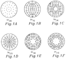
- Figs. 1A-1F disclose for illustrative purposes the lower order TM nmp field distributions for a circular parallell-plate resonator, i.e. the TM 010 , TM 110 , TM 210 , TM 020 , TM 310 , TM 410 -modes.
- Solid lines indicate the current
- dashed lines indicate the magnetic field
- the field/current distributions are fixed in space by coupling arrangements (coupling loop, coupling probe, or a second resonator).
- the current distributions for interfering (non TM 0i0 ) modes are "peaking" near the edges of a resonator disk, i.e. the peak values of the currents are near the circumference of the disk. (See also Fig. 3 to Fig. 10).
- Parallel-plate resonators e.g. in the form of circular dielectric disks and circular patches on dielectric substrates, may find a number of microwave applications.
- the resonators are regarded electrically thin if their thickness is smaller then the wavelength of the microwave signals in the resonator, d ⁇ /2 , so that no standing waves are present along the axis of the disk.
- the above formula may be corrected taking fringing fields into account.
- Attractive for filter applications are e.g. the axially symmetric modes with the plate currents only in radial direction. These modes are characterized by higher quality (Q) factors since they do not have surface currents along the edges of conductor plates. Extremely high Q-factors in circular patch resonators with HTS plates have been achieved due to the exploitation of the first axially symmetric mode.
- This mode is widely regarded as TM 010 as a mode accommodating one antinode in the radial direction.
- the mode TM 110 should also have one antinode along the radius, which is not true. In all published presentations this TM 110 has one antinode along the diameter.
- the first axially symmetric mode should be denoted as TM 020 , instead of TM 010 .
- This incorrect interpretation of mode indexes leads to confusion not only for TM 010 , but also for the other modes, and moreover, to incorrect interpretation of experimentally observed higher order modes, especially for multi-mode resonators.
- correct identification of experimentally observed modes is a critical issue in the evaluation of the field/current distributions in the resonators. Knowledge of these distributions is required particularly in the designing of coupling elements (probe, loop), coupling between resonators in multiresonator filters, in case of designing of mode selective components in multi-mode resonators etc.
- Table I summarizes the roots, k nm ,of twenty modes given in increasing order, to reflect increasing order of resonant frequencies.
- the table indicates mode indexes and numbers of field maximas and it is useful in computations, where absolute values of wavenumber. are required for resonant frequency computation, evaluation of field/current distributions or evaluation of equivalent circuit parameters and Q-factors of the modes.
- Mode Roots of J' n (k nm ) 0 Mode indices Number of field maxima TM nm0 k nm Angular n Radial m Angular p Diametrical q 1 TM 010 0 0 1 0 0 2 TM 110 1.8412 1 1 1 1 3 TM 210 3.0542 2 1 2 2 4 TM 020 3.8317 0 2 0 2 5 TM 310 4.2012 3 1 3 2 6 TM 410 5.3176 4 1 4 2 7 TM 120 5.3314 1 2 1 3 8 TM 510 6.4156 5 1 5 2 9 TM 220 6.7061 2 2 2 4 10 TM 030 7.0156 0 3 0 4 11 TM 610 7.5013 6 1 6 2 12 TM 320 8.0152 3 2 3 4 13 TM 130 8.5363 1 3 1 5 14 TM 710 8.5778 7 1 7 2 15 TM 420 9.2824 4 2 4 4 16 TM 810 9.6474 8 1 8 2 17 TM
- Figs. 1A-1F Some of the mode field distributions, in any plane parallel to the plate, in the form of vector plots are shown in a simplified manner in Figs. 1A-1F.
- the vector plots of surface currents have similar patterns where the vectors in Fig. 1A-1F are rotated 90°, owing to the simple relationship between surface currents and tangential magnetic fields, where z is a unit vector normal to the surface of the plate.
- Indexes n and m shown in Table I have straightforward mathematical explanations in terms of solutions of equation i.e. they indicate the angular and radial numbers of zeros of Bessel functions and magnetic field. In other words these are angular and radial mode indices.
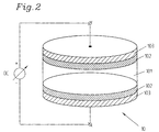
- Fig. 2 shows an example of a circular parallell-plate resonator 10 in which a non-linear bulk dielectric substrate 101, which has a high dielectric constant, is covered by two superconducting films 102, 102 on either side thereof.
- the low loss non-linear dielectric substrate 101 and the two superconducting films 102, 102 (below their critical temperature) comprise a microwave parallell-plate resonator 10 with a high quality factor, also called a Q-factor.
- a tunable voltage Via a variable DC-voltage source a tunable voltage may be applied.
- an electrically tunable resonator is shown, the invention is of course not limited to electrically tunable devices - this merely constitutes an example.
- the resonators may also be tunable by other means or not tunable.
- the superconducting films 102, 102 may be high temperature superconducting films although they do not have to be such films, they may also be normally superconducting or normally conducting. In the illustrated embodiment the superconducting films are covered by non-superconducting high conductivity films 103, 103 of for example gold, silver, copper or similar. Such devices are further discussed in "Tunable Microwave Devices" which is a Swedish patent application filed by the same applicant as referred to earlier. Also other parallell-plate resonators can however be used for example with only metal plates on either side of a substrate.
- the invention is not limited to any particular kind of parallell-plate resonators and any low loss dielectricum can be used, such as for example alumina (Al 2 O 3 ), zapphire, quartz, STO (SrTiO 3 ).
- Parallell-plate resonators as disclosed in the above mentioned Swedish patent application, which was incorporated herein by reference, are proposed e.g. for low loss narrow band filter applications.
- electrically thin parallell-plate resonators which have a thickness smaller than ⁇ g /2, wherein ⁇ g is the wavelength in the resonator
- the higher order TM modes have higher quality factors.
- the field generates currents in both plates.
- Fig. 3 shows an example with current interrupting means interrupting the maxima of the current lines of the TM 110 mode.
- the current interrupting means 1 in this embodiment consists of a cut or slot 1.
- the cut 1 is arranged diametrically accross the resonator plate orthogonally to the current lines.
- current interrupting means 2A, 2B, 2C, 2D are used to interrupt the current lines of the TM 210 mode and also in this embodiment the current interrupting means consist of cuts/slots directed towards the center (substantially) of the plate. The cuts are wider at the periphery and ends before the midpoint so as to cut the current lines of the undesired mode at the maximum and as little as possible affect main useful modes, for which the current has a maximum approximately at the midpoint. This is also illustrated in Figs. 6,7 and 9.
- the current interrupting means 3 are arranged to interrupt the current lines of the TM 020 mode and comprises a cut/slot in parallell to the periphery of the circular parallell-plate resonator and extending throughout at least 180°.
- the current interrupting means are also here provided at the maximum of the current distribution of the undesired mode which here is TM 020 .
- current interrupting means 4A-4F comprise cuts/slots interrupting the TM 310 mode whereas in Fig. 7 current interrupting means (also here cuts/slots) 5A-5H interrupt the TM 410 mode.
- the current interrupting means of Figs. 3-7 can be arranged either in/on one of the plates of the parallell-plate resonator or in both.
- the angle between the current interrupting means is the same as the angles between the current distribution pattern. In case they are arranged on one plate only, the angles between their respective current interrupting means 2A, 2B, 2C, 2D are identical.
- the current interrupting means 4A, 4B, ... are also identical and equal to 60°.
- the current interrupting means 5A,...5H are arranged at angles being identical to 45°.
- the behavior is similar for higher order modes (not shown herein).
- the current interrupting means as disclosed above may be provided for both plates of a parallell-plate resonator. Then the angles may be 90°, 60° or 45° respectively. Of course also other angles are possible.
- Figs. 3-7 all relate to current interrupting means in the form of cuts or slots.
- the current interrupting means comprise resistive films replacing metal strips along the current lines of undesired modes or of removed metal parts in one or both electrode plates.
- the resistive films may be arranged on either one or both of the plates.
- the current interrupting means may still be arranged as discussed above. The current patterns are fixed in space and the current interrupting means are fixed in relation to the current patterns; otherwise it will not function.
- Fig. 8 an embodiment is illustrated in which the current interrupting means 6A, 6B, 6C, 6D comprise a resistive film suppressing TM 110 and TM 210 modes.
- the angles between the films or removed parts or resistive films are equal to 90° as also discussed above.
- Current interrupting means in the form of a resistive film may with advantage be used when whole electrode plates are desired, which for example is the case for electrically tunable resonators.
- the shape is such that it is wider at the periphery and narrower at the midpoint or ends before the midpoint, c.f. discussion above with reference to Fig. 4.
- Fig. 9 shows an embodiment in which the current interrupting means 7A-7D comprise removed parts in an electrode (or both electrodes as discussed above). Also in this case only the TM 020 mode is supported if the angles between the removed parts are equal to 90°.
- the number of cuts or slots or resistive strips and the corresponding widths thereof are made as small as possible in order not to affect the Q-factor of the desired mode, i.e. the effect on desired modes is minimized.
- Fig. 10 shows an embodiment in which the current interrupting means 8 comprises removed metal film and in this embodiment only the TM 210 mode is kept.
- Fig. 11A very schematically illustrates a cross-sectional view of a three pole filter 30 based on the selected TM 020 mode.
- Fig. 11B shows the top-electrode plates 302A, 302B, 302C of the three pole filter of Fig. 11A.
- the three pole filter is electrically tunable and parts 9A, 9B, 9C, 9D are removed from the electrodes.
- the angles between the respective removed parts corresponding to the current interrupting means are equal to 90°.
- the current interrupting means are only provided on the top electrodes.
- a similar pattern may be formed on the bottom plates 302C 1 .
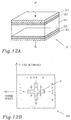
- Fig. 12A schematically illustrates a square-shaped parallell-plate resonator 20.
- a substrate 201 is wished on either side by electrodes 202, 202, which may be superconductors.
- non-superconducting high conductivity films 203, 203 are in turn provided on the superconductors. These are not necessary for the functioning.
- films 202, 203 may simply a metal conductor be provided.
- the parallell-plate resonator is electrically tunable which however of course not is necessarily the case.
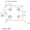
- Fig. 12C a parallell-plate square-shaped resonator similar to that of Fig. 12B is illustrated.
- the invention can be varied in a number ways within the scope of the claims.
- the invention is not limited to the explicitly shown resonators or filters but it can be used for in principle any parallell-plate resonator, filter or similar. More generally it can be implemented for any microwave device requiring precise mode selectivity and which is based on parallell-plate resonators. Particularly the inventive concept is implementable on all devices illustrated in "Tunable Microwave Devices" as disclosed in the earlier mentioned Swedish patent application, SE 9502137-4.
Landscapes
- Control Of Motors That Do Not Use Commutators (AREA)
Abstract
The present invention relates to a microwave device which
comprises a number of parallell-plate resonators which comprises
at least one dielectric substrate with first and second plates
arranged on either side thereof. At least one of said first and
second plates of each of a number of said parallell-plate
resonators is patterned/formed in such a way, or in other words
comprises current interrupting means (2A, 2B, 2C, 2D), such that
the current lines of at least one undesired mode are interrupted
at their maxima to suppress said undesired mode(s). The invention
also relates to a method of interrupting undesired modes in a
microwave device comprising a number of parallell-plate
resonators.
Description
- The present invention relates to microwave devices comprising a number of parallell-plate resonators allowing selection of modes. The invention also relates to a method of suppressing undesired modes in a microwave device.
- It is often desirable to be able to select the modes of microwave devices such as microwave resonators and filters. WO 98/32187 shows the use of aperiodic gratings for mode conversion/ selection. However, the grating structures/surfaces are of complex shape and long. These devices furthermore suffer the drawback of being complicated and costly to fabricate and it is also difficult to obtain a mode selectivity which is as accurate as would be desired. Still further they can not be used for thin film resonators for which the thickness is less then λg/2, λg being the wavelengths of the microwave signal in the resonator. In several implementations it is however desirable to be able to use such resonators. Still further, the size of the resonators is changed when structures as in WO 98/32187 are used.
- The Swedish patent application SE 9502137-4 discloses parallell-plate resonators, specially with superconducting plates for low-loss narrow-band filter applications. In "Lower Order Modes of YBCO/STO/YBCO Circular Disc Resonators", IEEE Transactions on Microwave Theory and Technics, Vol. 44 (10), pp. 1738-1741, 1996, it is shown that in electrical thin resonators (the thickness being smaller than λg/2), the higher order TM modes, so called whispering gallery modes, have higher quality factors. It would thus be desirable to utilize these modes in low loss narrow band filter applications. It is however a drawback related to using higher order modes since due to the resonant frequencies of these modes being very close to each other, the rejection bands of for example filters have parasitic undesirable transmission poles, i.e. in other words they are not spurious free. SE 9701450-0 "Arrangement and method relating to microwave devices" suggests one way to overcome this problem through the use of special mode selective coupling loops. However, such a device is comparatively bulky and most suitable for input/output coupling of resonators in multiresonator filters. Furthermore, since the coupling loops are quite bulky for certain applications, the parasitic modes will not be sufficiently suppressed. Still further such coupling loops are not possible to use in the resonators away from the input/output ports of for example filters.
- US-A-5 710 105 shows high power, high temperature superconductor filters having TM0i0 mode circular shaped high temperature superconductor planar resonators. To suppress interfeting non TM0i0 modes, radially directed slots are provided which are positioned parallell to the current of the desired operating mode and perpendicular to the current of an undesired mode. However, these slots are centered at the radius of the disk. They do not cut the maxima. Moreover such slots will affect the useful modes. Thus this device will not work as efficiently as needed. Moreover, this document merely contemplates the TM0i0-modes as attractive for selection.
- Therefore microwave devices, particularly microwave resonators and filters, are needed which are mode selective, particularly with a precise mode selectivity. Particularly devices are needed wherein means enabling mode selectivity are provided which are suitable for use for input/output coupling as well as away from input/output ports of resonators of filters. Particularly a device is needed which is small and for example comprises thin resonators, particularly having a thickness smaller than λg/2, λg being the microwave wavelength in the resonator. Still further a device is needed through which it is possible to use higher order TM modes in low loss narrow band filter applications. Particularly a device is needed through which higher order modes having close resonant frequencies can be used and through which parasitic and undesirable transmission poles can be avoided. Particularly a device is needed through which any standard thin film fabrication technology can be used and through which mode selectivity is enabled without changing the size of the resonators. Still further a device is needed which generally is cheap and easy to fabricate and through which the use of higher order TM modes is enabled without problems being caused by the close resonant frequencies of such modes. A method of suppressing undesired modes in such devices is also needed. A device and a method respectively is also needed which is more efficient in suppressing undesired modes than hitherto known devices at the same time as the effect of the suppression of undesired modes on the desired modes is minimized. Further yet a device and a method respectively is needed through which any mode can be selected or suppressed.
- Therefore a microwave device is provided which particularly comprises a number of parallell-plate resonators. Each parallell-plate resonator comprises at least one dielectric substrate with first and second conducting (superconducting) plates arranged on either side of said dielectric substrate. The field (the field produced by coupling arrangement or similar, e.g. discussed in the applications by the same applicant which are incorporated herein by reference above) generates currents in both of said plates of the parallell-plate resonator or resonators (the resonator is thin). At least one of said first and second plates of each of a number of said parallell-plate resonators is patterned or formed in such a way, or comprises current interrupting means, that the current lines of at least one undesired mode are interrupted at their maxima (where the current lines have a maximum) to suppress said undesired mode or modes, thus providing for selectivity. The current interrupting means may be provided in a number of different ways, as actual means or as a particular pattern in, or forming of, the resonators. According to one embodiment the current interrupting means are constituted of cuts in at least one resonator plate of one or more parallell-plate resonators. Particularly the resonator plates comprise metal and the current interrupting means consists of metal being removed except for along the current lines of the desired modes which in other words means that the parallell-plate resonator is patterned or formed in such a way.
- In an alternative embodiment, the resonator plates comprising metal strips, are the current interrupting means formed by resistive strips arranged along the current lines of the undesired modes, thus replacing said metal strips. This is particularly convenient if the device comprises a number of electrically tunable resonators requiring whole resonator plates, i.e. resonator plates which should not contain any cuts or similar. Also in other implementations requiring "whole" resonator plates this implementation consisting of replacing metal strips through resistive strips, is appropriate.
- For parallell-plate resonators, or devices built of or including parallell-plate resonators, the current interrupting means may either be provided on one only of the resonator plates of a respective parallell-plate resonator or current interrupting means may be provided on both plates. In a particular implementation the device comprises one or more circular parallell-plate resonators.
- Particularly one or more modes are suppressed. In some embodiments the current interrupting means, i.e. the cuts, resistive films or removed metal parts, are arranged to interrupt the current lines of for example one or more of the TM210, TM310 and TM410 modes respectively. Then a number of current interrupting means are arranged which are directed substantially towards the center of the circular parallell-plate resonator. The current interrupting means are so formed that they have a larger width at the edge of the disc whereas the width is substantially zero, or zero, at the midpoint or at a distance from the midpoint thus promoting the desired modes, or not affecting the desired modes.
- In one embodiment the current interrupting means are arranged at a distance from the periphery and along at least a part (exceeding 180°) in the form of a stripe or similar of at least one plate to suppress the TM020 mode. In one embodiment current interrupting means are arranged to suppress the TM110 mode and the current interrupting means are then arranged along a diameter of at least one of the resonator plates and forming substantially 90° of the current lines to suppress said mode.
- In alternative embodiments a parallell-plate resonator is rectangular, square-shaped or of any appropriate regular or irregular shape.
- In a number of alternative embodiments current interrupting means are provided for both plates of a parallell-plate resonator. The current interrupting means of each of the plates of a parallell-plate resonator may then be similar and symmetrical. Also in this case a parallell-plate resonator may be circular, square-shaped, rectangular or of any other convenient shape.
- In a particular embodiment the device relates to a filter formed of a number of parallell-plate resonators as referred to above. In a particular implementation the filter is a narrow-band filter.
- The electric substrate of the resonator may consists of different materials such as alumina (Al2O3), zapphire, quartz, STO etc. The plates may be normal metal plates, superconducting plates or particularly high temperature superconducting. The inventive concept is particularly applicable on devices as disclosed in the Swedish patent application "Tunable Microwave Devices", 9502137-4, which hereby is incorporated herein by reference. The device enabling exact mode selectivity can advantageously be used in wireless communication systems.
- A method of suppressing undesired modes in a microwave device which comprises a number of parallell-plate resonators wherein each resonator includes a first and a second plate and wherein a field generates currents in both of said electrode plates is disclosed which comprises the step of interrupting the maximas of the current lines of the undesired modes in at least one of said plates. According to one implementation the method comprises the step of providing cuts/slots to interrupt the current lines of the undesired mode or modes in the maximas in at least one of the plates. In a particular implementation symmetric cuts/slots are provided in both electrode plates.
- In an alternative embodiment a method comprises the step of removing electrode plates throughout at least one of the plates except for along the current lines of the desired mode or modes. In still another embodiment a method includes the step of arranging resistive strips along the current lines of undesired modes as a replacement for existing metal strips of said resonator plate or plates.
- According to the invention the cuts/slots/resistive strips/removed material are positioned predominantly at the maximas of the current lines or current distribution of the modes to be suppressed and at the minimas of the current lines (distribution of the desired modes).
- The slot etc. may in general have a rectangular shape, but preferably their shape is selected based on the current distribution of undesired modes such that they are maximally suppressed while leaving the desired modes to the highest possible extent unaffected. Thus a careful observation of the maximas of current lines of undesired modes is highly important.
- Moreover, according to the inventive concept also other modes than the TM0i0 or particularly TM020, can be selected as desired modes. Such other modes may have a higher Q-factor which make them very attractive for the fabrication of the filters.
- The invention will in the following be further described in a non-limiting way and with reference to the accompanying drawings, in which:
- FIGS 1A-1F
- show current lines (field distribution) for a number of different TM-modes for a circular parallell-plate resonator,
- FIG 2
- shows an example of a circular parallell-plate resonator,
- FIG 3
- shows an example on current interrupting means suppressing the TM110 mode,
- FIG 4
- illustrates an embodiment in which the TM210 mode is suppressed,
- FIG 5
- is an embodiment illustrating current interrupting means for suppressing the TM020 mode,
- FIG 6
- shows an embodiment of current interrupting means suppressing the TM310 mode,
- FIG 7
- shows current interrupting means suppressing the TM410 mode,
- FIG 8
- shows one embodiment for suppressing the TM110 and TM210 modes,
- FIG 9
- shows an alternative embodiment for suppressing the TM110 and TM210 modes respectively,
- FIG 10
- shows an embodiment for supporting only the TM210 mode,
- FIG 11A
- schematically illustrates a cross-section of a three pole filter,
- FIG 11B
- illustrates current interrupting means for the filter of Fig. 11A in which the TM020 mode is selected,
- FIG 12A
- schematically illustrates a rectangular parallell-plate resonator,
- FIG 12B
- shows an implementation of the rectangular parallell-plate resonator of Fig. 12A for suppressing the fundamental mode, and
- FIG 12C
- shows an implementation of a rectangular parallell-plate resonator of Fig. 12A for suppressing the mode having m=2.
- Figs. 1A-1F disclose for illustrative purposes the lower order TMnmp field distributions for a circular parallell-plate resonator, i.e. the TM010, TM110, TM210, TM020, TM310, TM410-modes. Solid lines indicate the current, dashed lines indicate the magnetic field and dots and crosses indicate the electric field. It is supposed that p=0, i.e. in other words that the thickness of the plate is smaller than a half wavelength in the resonator and that the resonator only supports TMnm0 modes. In all cases the field/current distributions are fixed in space by coupling arrangements (coupling loop, coupling probe, or a second resonator).
- The current distributions for interfering (non TM0i0) modes are "peaking" near the edges of a resonator disk, i.e. the peak values of the currents are near the circumference of the disk. (See also Fig. 3 to Fig. 10). Parallel-plate resonators e.g. in the form of circular dielectric disks and circular patches on dielectric substrates, may find a number of microwave applications. The resonators are regarded electrically thin if their thickness is smaller then the wavelength of the microwave signals in the resonator,where c0=3.108m/s is the velocity of light in vacuum, ε is the relative dielectric constant of disk/substrate, r is the radius of the conducting plate, and knm are the roots of Bessel functions with mode indexes n and m. For an electrically thin parallel-plate resonator the third index, 1=0. The above formula may be corrected taking fringing fields into account.

- Attractive for filter applications are e.g. the axially symmetric modes with the plate currents only in radial direction. These modes are characterized by higher quality (Q) factors since they do not have surface currents along the edges of conductor plates. Extremely high Q-factors in circular patch resonators with HTS plates have been achieved due to the exploitation of the first axially symmetric mode. This mode is widely regarded as TM010 as a mode accommodating one antinode in the radial direction. According to this approach the mode TM110 should also have one antinode along the radius, which is not true. In all published presentations this TM110 has one antinode along the diameter. It has been mentioned that the first axially symmetric mode should be denoted as TM020, instead of TM010. This incorrect interpretation of mode indexes leads to confusion not only for TM010, but also for the other modes, and moreover, to incorrect interpretation of experimentally observed higher order modes, especially for multi-mode resonators. On the other hand correct identification of experimentally observed modes is a critical issue in the evaluation of the field/current distributions in the resonators. Knowledge of these distributions is required particularly in the designing of coupling elements (probe, loop), coupling between resonators in multiresonator filters, in case of designing of mode selective components in multi-mode resonators etc. These and similar problems may be easily solved by using a mode chart of parallel-plate resonators as discussed below.
- For the purposes of mode chart discussions the fringing electric fields at the edges of the disk(s) may be ignored. This is equivalent to assuming a magnetic wall at the

- Jn (βρ) and J'n (βρ) are the bessel functions of the n-th order and their derivaties, β is the wavenumber, and ζ=0 or π/2, corresponding to two degenerate modes in a fully symmetric resonator. From (3) the magnetic wall approximation at ρ=r leads to
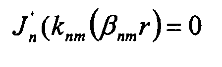
- Table I below summarizes the roots, knm,of twenty modes given in increasing order, to reflect increasing order of resonant frequencies. Indices m=1,2,3... shows the number of zeros of the J'n (βρ) function over the radius of the disk. The table indicates mode indexes and numbers of field maximas and it is useful in computations, where absolute values of wavenumber. are required for resonant frequency computation, evaluation of field/current distributions or evaluation of equivalent circuit parameters and Q-factors of the modes.
Mode Roots of J'n(knm)=0 Mode indices Number of field maxima TM nm0 k nm Angular n Radial m Angular p Diametrical q 1 TM010 0 0 1 0 0 2 TM110 1.8412 1 1 1 1 3 TM210 3.0542 2 1 2 2 4 TM020 3.8317 0 2 0 2 5 TM310 4.2012 3 1 3 2 6 TM410 5.3176 4 1 4 2 7 TM120 5.3314 1 2 1 3 8 TM510 6.4156 5 1 5 2 9 TM220 6.7061 2 2 2 4 10 TM030 7.0156 0 3 0 4 11 TM610 7.5013 6 1 6 2 12 TM320 8.0152 3 2 3 4 13 TM130 8.5363 1 3 1 5 14 TM710 8.5778 7 1 7 2 15 TM420 9.2824 4 2 4 4 16 TM810 9.6474 8 1 8 2 17 TM230 9.9695 2 3 2 6 18 TM040 10.1735 0 4 0 6 19 TM520 10.5199 5 2 5 4 20 TM910 10.7114 9 1 9 2 - Some of the mode field distributions, in any plane parallel to the plate, in the form of vector plots are shown in a simplified manner in Figs. 1A-1F. The vector plots of surface currents have similar patterns where the vectors in Fig. 1A-1F are rotated 90°, owing to the simple relationship between surface currents and tangential magnetic fields,where

z is a unit vector normal to the surface of the plate. Indexes n and m shown in Table I have straightforward mathematical explanations in terms of solutions of equationi.e. they indicate the angular and radial numbers of zeros of Bessel functions and magnetic field. In other words these are angular and radial mode indices.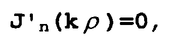
- Fig. 2 shows an example of a circular parallell-
plate resonator 10 in which a non-linearbulk dielectric substrate 101, which has a high dielectric constant, is covered by twosuperconducting films dielectric substrate 101 and the twosuperconducting films 102, 102 (below their critical temperature) comprise a microwave parallell-plate resonator 10 with a high quality factor, also called a Q-factor. Via a variable DC-voltage source a tunable voltage may be applied. Although an electrically tunable resonator is shown, the invention is of course not limited to electrically tunable devices - this merely constitutes an example. The resonators may also be tunable by other means or not tunable. - The
superconducting films high conductivity films - Fig. 3 shows an example with current interrupting means interrupting the maxima of the current lines of the TM110 mode. The current interrupting means 1 in this embodiment consists of a cut or slot 1. The cut 1 is arranged diametrically accross the resonator plate orthogonally to the current lines.
- In Fig. 4 current interrupting means 2A, 2B, 2C, 2D are used to interrupt the current lines of the TM210 mode and also in this embodiment the current interrupting means consist of cuts/slots directed towards the center (substantially) of the plate. The cuts are wider at the periphery and ends before the midpoint so as to cut the current lines of the undesired mode at the maximum and as little as possible affect main useful modes, for which the current has a maximum approximately at the midpoint. This is also illustrated in Figs. 6,7 and 9.
- In Fig. 5 the current interrupting
means 3 are arranged to interrupt the current lines of the TM020 mode and comprises a cut/slot in parallell to the periphery of the circular parallell-plate resonator and extending throughout at least 180°. The current interrupting means are also here provided at the maximum of the current distribution of the undesired mode which here is TM020. - In Fig. 6 current interrupting means 4A-4F comprise cuts/slots interrupting the TM310 mode whereas in Fig. 7 current interrupting means (also here cuts/slots) 5A-5H interrupt the TM410 mode.
- The current interrupting means of Figs. 3-7 can be arranged either in/on one of the plates of the parallell-plate resonator or in both. The angle between the current interrupting means is the same as the angles between the current distribution pattern. In case they are arranged on one plate only, the angles between their respective current interrupting means 2A, 2B, 2C, 2D are identical. The current interrupting means 4A, 4B, ... are also identical and equal to 60°. Finally the current interrupting means 5A,...5H are arranged at angles being identical to 45°. The behavior is similar for higher order modes (not shown herein). According to other embodiments, not shown explicitly herein, the current interrupting means as disclosed above may be provided for both plates of a parallell-plate resonator. Then the angles may be 90°, 60° or 45° respectively. Of course also other angles are possible.
- Figs. 3-7 all relate to current interrupting means in the form of cuts or slots. However, in alternative embodiments the current interrupting means comprise resistive films replacing metal strips along the current lines of undesired modes or of removed metal parts in one or both electrode plates. Of course also the resistive films may be arranged on either one or both of the plates. The current interrupting means may still be arranged as discussed above. The current patterns are fixed in space and the current interrupting means are fixed in relation to the current patterns; otherwise it will not function.
- In Fig. 8 an embodiment is illustrated in which the current interrupting means 6A, 6B, 6C, 6D comprise a resistive film suppressing TM110 and TM210 modes. The angles between the films or removed parts or resistive films are equal to 90° as also discussed above. Current interrupting means in the form of a resistive film may with advantage be used when whole electrode plates are desired, which for example is the case for electrically tunable resonators.
- Also when the current interrupting means are provided in form of resistive films or removed parts, advantageously the shape is such that it is wider at the periphery and narrower at the midpoint or ends before the midpoint, c.f. discussion above with reference to Fig. 4.
- Fig. 9 shows an embodiment in which the current interrupting means 7A-7D comprise removed parts in an electrode (or both electrodes as discussed above). Also in this case only the TM020 mode is supported if the angles between the removed parts are equal to 90°.
- In all the embodiments disclosed above, the number of cuts or slots or resistive strips and the corresponding widths thereof are made as small as possible in order not to affect the Q-factor of the desired mode, i.e. the effect on desired modes is minimized.
- Fig. 10 shows an embodiment in which the current interrupting
means 8 comprises removed metal film and in this embodiment only the TM210 mode is kept. - Fig. 11A very schematically illustrates a cross-sectional view of a three
pole filter 30 based on the selected TM020 mode. - Fig. 11B shows the top-
electrode plates 302A, 302B, 302C of the three pole filter of Fig. 11A. The three pole filter is electrically tunable andparts 9A, 9B, 9C, 9D are removed from the electrodes. The angles between the respective removed parts corresponding to the current interrupting means are equal to 90°. In the threepole filter 30 301 corresponds to the substrate, 302C correspond to the respective upper electrodes whereas 302C1 corresponds to the bottom electrode plates. In this particular embodiment the current interrupting means are only provided on the top electrodes. Of course, in an alternative embodiment a similar pattern may be formed on the bottom plates 302C1. - Fig. 12A schematically illustrates a square-shaped parallell-
plate resonator 20. Like in Fig. 2 asubstrate 201 is coveted on either side byelectrodes high conductivity films films substrate 101. Also in this case the parallell-plate resonator is electrically tunable which however of course not is necessarily the case. - In Fig. 12B a square-shaped parallell-plate resonator is illustrated having length and width equal to L. Also illustrated in the figure are the charge distribution and the charged density. Plus (+) and minus (-) in the figure indicate the charges. In Fig. 12B current interrupting means 11 are arranged which are used to suppress the fundamental (m=1) mode.
- In Fig. 12C a parallell-plate square-shaped resonator similar to that of Fig. 12B is illustrated. In this case current interrupting means 12A, 12B, 12C, 12D are illustrated which are used to suppress the mode with m=2. It should all be clear that these only constitute examples on current interrupting means in the form of cuts or removed plate for suppressing some particular modes. A number of alternatives are of course also possible like for the circular resonators.
- It should be clear that the invention can be varied in a number ways within the scope of the claims. The invention is not limited to the explicitly shown resonators or filters but it can be used for in principle any parallell-plate resonator, filter or similar. More generally it can be implemented for any microwave device requiring precise mode selectivity and which is based on parallell-plate resonators. Particularly the inventive concept is implementable on all devices illustrated in "Tunable Microwave Devices" as disclosed in the earlier mentioned Swedish patent application, SE 9502137-4.
Claims (23)
- Microwave device (10;20;20A;20B;30) comprising a number of parallell-plate resonators (10;20;20A;20B), each comprising at least one dielectric substrate (101;201;301) with first and second (superconducting) plates (102;202;302A;302B;302C) arranged on either side of said dielectric substrate, a field generating currents in both of said plates of said parallell-plate resonators,
characterized inthat at least one of said first and second plates (102;202;302A;302B;302C) of each of a number of said parallell-plate resonators (10;20;20A;20B) is patterned/formed in such a way or comprises current interrupting means (1;2A-2D;3;4A-4E;5A-5G; 7A-7D;11;12A-12D), that the current lines of at least one undesired mode are interrupted substantially at the maxima of said current lines to suppress said undesired mode(s). - A device according to claim 1,
characterized inthat the current interrupting means are constituted of cuts or slots positioned predominantly at the maxima of the current lines of mode(s) to be suppressed and at the minima of the current lines of desired mode(s) (1;2A-2D;3;4A-4E;5A-5G;7A-7D;11;12A-12D) in at least one resonator plate of one or more parallell-plate resonators. - A device according to claim 1,
characterized inthat the resonator plates comprise metal, and in that the current interrupting means are formed by metal being removed (8) except for along the current lines of the desired modes. - A device according to claim 1,
characterized inthat the resonator plates comprise metal strips (6A-6D) and inthat the current interrupting means comprise resistive strips which are arranged along the current lines of the undesired modes, replacing metal strips, the shape of the resistive strips being given by the current distribution of modes such that undesired modes are maximally suppressed and desired modes are minimally affected. - A device according to claim 4,
characterized inthat the device comprises a number of electrically tunable resonators. - A device according to any one of the preceding claims,
characterized inthat only one of the resonator plates of each parallell-plate resonators comprises current interrupting means or is patterned/formed so that the current lines of the undesired modes are interrupted. - A device according to any one of the preceding claims,
characterized inthat it comprises a circular parallell-plate resonator (10). - A device according to claim 7,
characterized inthat the current interrupting means, i.e. the cuts, slots, resistive films or removed metal parts, are arranged to interrupt the current lines of for example one or more of TM210, TM310 and TM410 modes, requiring a number of centrally directed current interrupting means and in that the angles between said current interrupting means are the same and equal to 45°, 60° or 90° respectively for TM210, TM310 and/or TM410 etc. respectively, and inthat the current interrupting means are wider at the periphery and narrower towards the midpoint. - A device according to any one of claims 1-6,
characterized inthat the current interrupting means (3) are radially arranged all around or along a part (at least forming 180°) of at least one plate to suppress the TM020 mode, at the same distance from the periphery. - A device according to any one of claims 1-6,
characterized inthat the current interrupting means (1) are arranged along a diameter of at least one of the resonator plates forming substantially 90° with the current lines to suppress the TM110 mode. - A device according to claim 6,
characterized inthat the parallell-plate resonator is rectangular, square-shaped (20;20A;20B) or of any appropriate regular or irregular shape. - A device according to claim any one of claims 1-5,
characterized inthat current interrupting means are provided for both plates of a parallell-plate resonator. - A device according to any one of claims 1-8,11 or 12,
characterized inthat the current interrupting means are arranged to interrupt the current lines of e.g. one or more of TM210, TM310 and TM410 and inthat the current interrupting means are centrally directed (20A-20D;4B-4F;5A-5H;6A-6D;7A-7D), the angles between the interrupting means being the same and e.g. corresponding to one or more of 45°, 60°, 90° respectively for interrupting the current lines of the undesired mode(s). - A device according to claim 12,
characterized inthat the parallell-plate resonator is square-shaped, rectangular or of any other convenient shape. - A device according to any one of the preceding claims,
characterized inthat it comprises a filter (30) formed by a number of parallell plate resonators. - A device according to claim 15,
characterized inthat it comprises a narrow-band filter. - A device according to any one off the preceding claims,
characterized inthat the dielectric substrate (101;201;301) comprises alumina (Al2O3), zapphire, quartz, STO etc. - Use of the device of any one of preceding claims in a wireless communication system.
- Method of suppressing undesired modes in a microwave device comprising a number of parallell-plate resonators, each resonator including a first and a second plate and wherein an applied field generates currents in both of said electrode plates,
characterized inthat it comprises the step of:interrupting the current lines of the undesired mode(s) in at least one of said plates at the maxima of the current lines. - A method according to claim 19,
characterized inthat it comprises the step of:providing cuts or slots to interrupt the current lines of the undesired mode(s) in at least one of said plates. - A method according to claim 20,
characterized inthat it comprises the step of:providing symmetric cuts or slots in both electrode plates. - A method according to claim 19 or 20,
characterized inthat it comprises the step of:removing metal throughout at least one of the plates except for along the current lines of the desired mode(s). - A method according to claim 19 or 20 for suppressing undesired modes for a number of resonators requiring whole plates,
characterized inthat it comprises the step of:arranging resistive strips along the current lines of undesired modes as a replacement for existing metal strips of the resonator plates.
Applications Claiming Priority (2)
| Application Number | Priority Date | Filing Date | Title |
|---|---|---|---|
| SE9901190A SE9901190L (en) | 1999-04-01 | 1999-04-01 | Microwave devices and method related thereto |
| SE9901190 | 1999-04-01 |
Publications (1)
| Publication Number | Publication Date |
|---|---|
| EP1041669A1 true EP1041669A1 (en) | 2000-10-04 |
Family
ID=20415088
Family Applications (1)
| Application Number | Title | Priority Date | Filing Date |
|---|---|---|---|
| EP00106586A Withdrawn EP1041669A1 (en) | 1999-04-01 | 2000-03-27 | Microwave devices and method relating thereto |
Country Status (5)
| Country | Link |
|---|---|
| US (1) | US6501972B1 (en) |
| EP (1) | EP1041669A1 (en) |
| JP (1) | JP2001136009A (en) |
| SE (1) | SE9901190L (en) |
| TW (1) | TW441147B (en) |
Cited By (1)
| Publication number | Priority date | Publication date | Assignee | Title |
|---|---|---|---|---|
| WO2005124926A1 (en) * | 2004-06-17 | 2005-12-29 | Oleg Muzyrya | Ferroelectric antenna |
Families Citing this family (5)
| Publication number | Priority date | Publication date | Assignee | Title |
|---|---|---|---|---|
| SE519705C2 (en) * | 2001-08-22 | 2003-04-01 | Ericsson Telefon Ab L M | A tunable ferroelectric resonator device |
| UA110214C2 (en) * | 2013-03-04 | 2015-12-10 | Usykov Inst Of Radio Physics And Electronics Of The Nat Academy Of Sciences Of Ukraine O | Measuring resonator whispering gallery waves |
| US10665634B2 (en) * | 2016-02-02 | 2020-05-26 | Massachusetts Institute Of Technology | Distributed nanowire sensor for single photon imaging |
| NO347026B1 (en) * | 2020-03-25 | 2023-04-24 | Roxar Flow Measurement As | Multiphase salinity and watercut measurements |
| CN111987403B (en) * | 2020-07-10 | 2021-07-16 | 深圳大学 | Geometrically shaped microwave resonators |
Citations (4)
| Publication number | Priority date | Publication date | Assignee | Title |
|---|---|---|---|---|
| US4233579A (en) * | 1979-06-06 | 1980-11-11 | Bell Telephone Laboratories, Incorporated | Technique for suppressing spurious resonances in strip transmission line circuits |
| US4238747A (en) * | 1979-08-10 | 1980-12-09 | The United States Of America As Represented By The Secretary Of The Air Force | Mode filter apparatus |
| RU2012954C1 (en) * | 1990-07-09 | 1994-05-15 | Тольяттинский филиал Московского технологического института | Microstrip resonator |
| US5710105A (en) * | 1995-05-11 | 1998-01-20 | E. I. Du Pont De Nemours And Company | TM0i0 mode high power high temperature superconducting filters |
Family Cites Families (5)
| Publication number | Priority date | Publication date | Assignee | Title |
|---|---|---|---|---|
| US3775694A (en) * | 1973-02-02 | 1973-11-27 | Gen Electric | Amplifier for microwaves comprising radial waveguide-hybrid coupler |
| JPS63500559A (en) * | 1985-10-03 | 1988-02-25 | ヒユ−ズ・エアクラフト・カンパニ− | Non-reactive radiation power divider/combiner with integral mode filter |
| US5172084A (en) | 1991-12-18 | 1992-12-15 | Space Systems/Loral, Inc. | Miniature planar filters based on dual mode resonators of circular symmetry |
| SE506313C2 (en) | 1995-06-13 | 1997-12-01 | Ericsson Telefon Ab L M | Tunable microwave appliances |
| SE506303C2 (en) * | 1995-06-13 | 1997-12-01 | Ericsson Telefon Ab L M | Device and method of tunable devices |
-
1999
- 1999-04-01 SE SE9901190A patent/SE9901190L/en not_active Application Discontinuation
- 1999-04-15 TW TW088106030A patent/TW441147B/en not_active IP Right Cessation
-
2000
- 2000-03-27 EP EP00106586A patent/EP1041669A1/en not_active Withdrawn
- 2000-03-30 JP JP2000144183A patent/JP2001136009A/en active Pending
- 2000-03-31 US US09/539,797 patent/US6501972B1/en not_active Expired - Fee Related
Patent Citations (4)
| Publication number | Priority date | Publication date | Assignee | Title |
|---|---|---|---|---|
| US4233579A (en) * | 1979-06-06 | 1980-11-11 | Bell Telephone Laboratories, Incorporated | Technique for suppressing spurious resonances in strip transmission line circuits |
| US4238747A (en) * | 1979-08-10 | 1980-12-09 | The United States Of America As Represented By The Secretary Of The Air Force | Mode filter apparatus |
| RU2012954C1 (en) * | 1990-07-09 | 1994-05-15 | Тольяттинский филиал Московского технологического института | Microstrip resonator |
| US5710105A (en) * | 1995-05-11 | 1998-01-20 | E. I. Du Pont De Nemours And Company | TM0i0 mode high power high temperature superconducting filters |
Non-Patent Citations (2)
| Title |
|---|
| PATENT ABSTRACTS OF JAPAN vol. 13, no. 196 (E - 755) 10 May 1989 (1989-05-10) * |
| SOVIET PATENTS ABSTRACTS Section EI Week 9505, 3 March 1995 Derwent World Patents Index; Class W02, AN 9503514205, XP002140848 * |
Cited By (1)
| Publication number | Priority date | Publication date | Assignee | Title |
|---|---|---|---|---|
| WO2005124926A1 (en) * | 2004-06-17 | 2005-12-29 | Oleg Muzyrya | Ferroelectric antenna |
Also Published As
| Publication number | Publication date |
|---|---|
| SE9901190D0 (en) | 1999-04-01 |
| SE9901190L (en) | 2000-10-02 |
| US6501972B1 (en) | 2002-12-31 |
| TW441147B (en) | 2001-06-16 |
| JP2001136009A (en) | 2001-05-18 |
Similar Documents
| Publication | Publication Date | Title |
|---|---|---|
| JP4021844B2 (en) | Tunable ferroelectric resonator device | |
| EP0832507B1 (en) | Tunable microwave devices | |
| US6538527B2 (en) | Resonator, filter, duplexer, and communication device | |
| US7902945B2 (en) | Dual mode ring resonator filter with a dual mode generating line disposed inside the ring resonator | |
| EP0764996B1 (en) | Dielectric resonator capable of varying resonant frequency | |
| CA2286997A1 (en) | General response dual-mode, dielectric resonator loaded cavity filter | |
| EP1777773A1 (en) | Electronically tunable dielectric resonator circuits | |
| US9614264B2 (en) | Filter | |
| JP2010527210A (en) | Zigzag array resonator for relatively high performance HTS applications | |
| EP1041669A1 (en) | Microwave devices and method relating thereto | |
| US6484043B1 (en) | Dual mode microwave band pass filter made of high quality resonators | |
| KR100362849B1 (en) | Apparatus and method related to tunable device | |
| Atia et al. | General TE/sub 011/-Mode Waveguide Bandpass Filters | |
| US6185441B1 (en) | Arrangement and method relating to coupling of signals to/from microwave devices | |
| JPH01236724A (en) | Chip for magnetostatic wave element and magnetostatic wave element | |
| US6069543A (en) | Dielectric resonator capable of varying resonant frequency | |
| JP4769830B2 (en) | Dual mode filter and tuning method | |
| JP2010028787A (en) | Dual mode filter | |
| Zhang | Novel Planar Microstrip and Dielectric Resonator Filters | |
| JPH01208001A (en) | Resonator device | |
| Crnojević-Bengin et al. | 7 Multi-band microstrip filters based |
Legal Events
| Date | Code | Title | Description |
|---|---|---|---|
| PUAI | Public reference made under article 153(3) epc to a published international application that has entered the european phase |
Free format text: ORIGINAL CODE: 0009012 |
|
| AK | Designated contracting states |
Kind code of ref document: A1 Designated state(s): AT BE CH CY DE DK ES FI FR GB GR IE IT LI LU MC NL PT SE |
|
| AX | Request for extension of the european patent |
Free format text: AL;LT;LV;MK;RO;SI |
|
| 17P | Request for examination filed |
Effective date: 20010321 |
|
| AKX | Designation fees paid |
Free format text: AT BE CH CY DE DK ES FI FR GB GR IE IT LI LU MC NL PT SE |
|
| STAA | Information on the status of an ep patent application or granted ep patent |
Free format text: STATUS: THE APPLICATION IS DEEMED TO BE WITHDRAWN |
|
| 18D | Application deemed to be withdrawn |
Effective date: 20031001 |