EP1041466A2 - Electronic wrist watch with an bearing detector - Google Patents
Electronic wrist watch with an bearing detector Download PDFInfo
- Publication number
- EP1041466A2 EP1041466A2 EP00301835A EP00301835A EP1041466A2 EP 1041466 A2 EP1041466 A2 EP 1041466A2 EP 00301835 A EP00301835 A EP 00301835A EP 00301835 A EP00301835 A EP 00301835A EP 1041466 A2 EP1041466 A2 EP 1041466A2
- Authority
- EP
- European Patent Office
- Prior art keywords
- bearing
- measurement
- circuit
- wrist watch
- electronic wrist
- Prior art date
- Legal status (The legal status is an assumption and is not a legal conclusion. Google has not performed a legal analysis and makes no representation as to the accuracy of the status listed.)
- Withdrawn
Links
Images




Classifications
-
- G—PHYSICS
- G04—HOROLOGY
- G04G—ELECTRONIC TIME-PIECES
- G04G21/00—Input or output devices integrated in time-pieces
- G04G21/02—Detectors of external physical values, e.g. temperature
-
- G—PHYSICS
- G04—HOROLOGY
- G04B—MECHANICALLY-DRIVEN CLOCKS OR WATCHES; MECHANICAL PARTS OF CLOCKS OR WATCHES IN GENERAL; TIME PIECES USING THE POSITION OF THE SUN, MOON OR STARS
- G04B47/00—Time-pieces combined with other articles which do not interfere with the running or the time-keeping of the time-piece
- G04B47/06—Time-pieces combined with other articles which do not interfere with the running or the time-keeping of the time-piece with attached measuring instruments, e.g. pedometer, barometer, thermometer or compass
- G04B47/065—Time-pieces combined with other articles which do not interfere with the running or the time-keeping of the time-piece with attached measuring instruments, e.g. pedometer, barometer, thermometer or compass with a compass
Definitions
- the present invention relates to an electronic wrist watch with an bearing detector and, more particularly, to start and end of bearing measurement in an electronic wrist watch with an bearing detector.
- a conventional electronic wrist watch with an bearing detector is structured, for example shown by a block diagram in Fig. 7, a microprocessor (CPU) 10, a memory (ROM) 11 storing a system program, processing program and the like for the CPU 10, a memory (RAM) 12 storing processing data and the like, an oscillation circuit 13 for providing a clock signal to the CPU 10, a display circuit 14 driven by the CPU 10 and performing time display, bearing measurement value display and the like, an bearing detection circuit 15 controlled by the CPU 10 and performing bearing measurement, a frequency-dividing circuit 16 for frequency-dividing an oscillation frequency of the oscillation circuit 13 and generating a 1-Hz timing signal, a push button 17 for starting bearing measurement and a interrupt circuit 18.
- CPU microprocessor
- ROM read-only memory
- RAM random access memory
- an oscillation circuit 13 for providing a clock signal to the CPU 10
- a display circuit 14 driven by the CPU 10 and performing time display
- bearing measurement value display and the like an bearing detection circuit 15 controlled by the CPU 10 and performing bearing measurement
- the electronic wrist watch with an bearing detector is usually utilized by wearing on the arm, a wearer has been required to press a measurement push button 17 where starting bearing measurement.
- the wearer fully understands that measurement with the electronic wrist watch with an bearing detector positioned in a horizontal state is suited for bearing measurement.
- the push button 17 is pressed in a state that the electronic wrist watch with an bearing detector is not horizontal but inclined. If bearing measurement be made by the electronic wrist watch with an bearing detector in such an inclined state, there is a problem that measurement accuracy naturally lower.
- the problem that the invention is to solve is to improve bearing measurement accuracy by automatically starting bearing measurement when an electronic wrist watch with an bearing detector becomes into a horizontal state.
- a microprocessor In order to solve the above problem, provided are a microprocessor, a memory storing a processing program, processing data and the like for the microprocessor, an oscillation circuit for providing a clock signal to the microprocessor; a display circuit driven by the microprocessor to perform time display, bearing measurement value display and the like, and an bearing detection circuit controlled by the microprocessor to perform bearing measurement, wherein when the horizontal detection circuit detects a horizontal state of the electronic wrist watch with an bearing detector, bearing measurement and bearing measurement value display are performed.
- bearing measurement started by detecting a horizontal state of the electronic wrist watch with an bearing detector by the horizontal detection circuit is continued until a measurement stop signal is inputted. Further, the measurement stop signal is manually given by a push button or given after elapsing a predetermined time period by a timer.
- One embodiment of an electronic wrist watch with an bearing detector of the present invention is basically structured by adding to a conventional apparatus shown in Fig. 7 means to make bearing measurement and bearing measurement value display when detecting a horizontal state of the electronic wrist watch with an bearing detector.
- the one embodiment of an electronic wrist watch with an bearing detector is structured by a microprocessor (CPU) 10, a memory (ROM) 11 storing a system program, processing program and the like for the CPU 10, a memory (RAM) 12 storing processing data and the like, an oscillation circuit 13 for providing a clock signal to the CPU 10, a display circuit 14 driven by the CPU 10 and performing time display, bearing measurement value display and the like, an bearing detection circuit 15 controlled by the CPU 10 and performing bearing measurement, a frequency-dividing circuit 16 for frequency-dividing an oscillation frequency and generating a 1-Hz timing signal, a push button 17, an interrupt circuit 18 and a horizontal detection circuit 19 for generating a horizontal detection signal.
- CPU microprocessor
- ROM read-only memory
- RAM random access memory
- an oscillation circuit 13 for providing a clock signal to the CPU 10
- a display circuit 14 driven by the CPU 10 and performing time display
- bearing measurement value display and the like an bearing detection circuit 15 controlled by the CPU 10 and performing bearing measurement
- a frequency-dividing circuit 16 for frequency-
- the interrupt circuit 18 inputs a timing signal from the frequency-dividing circuit 16, an bearing measurement stop signal from the push button 17 and a horizontal detection signal from the horizontal detection circuit 19, respectively, to the CPU 10.
- the bearing measurement stop signal is possible to be generated by a timer, as hereinafter described.
- the horizontal detection circuit 19 is arranged within a case of the electronic wrist watch with an bearing detector or attached to the case. Consequently, the horizontal detection circuit 19 generates a horizontal detection signal when the electronic wrist watch with an bearing detector becomes into a horizontal state, and provides it to the interrupt circuit 18.
- the interrupt circuit 18 allows this horizontal detection signal to input to the CPU 10.
- the horizontal detection circuit 19 is provided with a horizontal sensor 20 as described below.
- the horizontal sensor 20 is comprised, for example as shown in a perspective view 5A, longitudinal sectional views 5B and 5C and a plan view with a lid removed 5D of Figs. 5, a circular container 21 of an insulation material having a generally-cylindrical interior chamber 21a, two conductive strip members 24a and 24b arranged within the circular container 21 to function as a pair of fixed contacts, and a conductive spherical member 25 enclosed in the circular container 21 to function as a movable contact.
- the circular container 21 is formed by a cup-formed lid member 22 and a dish-formed bottom member 23.
- the dish-formed bottom member 23 is formed by a conical surface 23a opened at a center with a small hole 23c and a horizontal surface 23b provided on an outer side thereof.
- the two conductive strip member 24a and 24b has respective outer ends projecting outside the container 21 to function as a pair of terminals, and respective inner end thereof extend to ends of small hole 23c of the bottom member 23 to function as a pair of fixed contacts.
- the two conductive strip members 24a and 24b at surfaces are exposed in the generally-cylindrical interior chamber 21a and buried in the bottom member 23.
- the conductive spherical member 25 functioning as a movable contact is enclosed within the generally-cylindrical interior chamber 21a of the container 21 so that it can freely rotate and move according to a gravity.
- the conductive spherical member 25 moves to and seat on the small hole 23c in the center of the bottom member 23, and electrically connects between the paired inner ends of the two conductive strip members 24a and 24b.
- the horizontal sensor 20 is inclined from a horizontal state, if inclined left for example, then as shown in Figs. 5C and 5D the conductive spherical member 25 leaves from the center small hole 23c of the bottom member 23 and moves to an end of the generally-cylindrical interior chamber 21a of the container 21, thus electrically disconnect the paired inner ends of the two conductive strip members 24a and 24b. In this manner, the horizontal sensor 20 electrically detects a horizontal state.
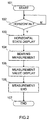
- Fig. 2 is a basic flowchart of bearing measurement start to end
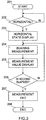
- Fig. 3 is a flowchart before automatically end after lapse of a predetermined time
- Fig. 4 is a flowchart before forcible end due to the push button.
- the horizontal detection circuit 19 start operation (101).
- the horizontal detection circuit 19 if detecting a horizontal state provides a horizontal detection signal to the interrupt circuit 18.
- the interrupt circuit 18 inputs the horizontal detection signal to the CPU 10.
- the CPU 10 determines that the electronic wrist watch with an bearing detector has become a horizontal state (102) and drives the display circuit 14 to perform horizontal state display (103).
- the CPU 10 drives the bearing detection circuit 15 to perform bearing measurement (104) and further drives the display circuit 14 to make bearing measurement value display (105).
- the CPU 10 ends the horizontal detection, bearing measurement and measurement value display (106).
- the series of operations are executed according to a content of a program stored in the ROM 11. In this manner, the electronic wrist watch with an bearing detector in an bearing measurement mode automatically starts bearing measurement if positioned in a horizontal state.
- the horizontal detection circuit 19 starts operation (201).
- the horizontal detection circuit 19 if detecting a horizontal state, provides a horizontal detection signal to the interrupt circuit 18.
- the interrupt circuit 18 inputs the horizontal detection signal to the CPU 10.
- the CPU 10 determines that the electronic wrist watch with an bearing detector becomes a horizontal state (202) and drives the display circuit 14 to make horizontal state display (203).
- the CPU 10 drives the bearing detection circuit 15 to perform bearing measurement (204) and further drives the display circuit 14 to perform bearing measurement value display (205).
- the CPU 10 determines whether or not 30 seconds has passed from a start of bearing measurement (206) and, if not elapsed by 30 seconds, continues the bearing measurement and measurement value display. In the case that 30 seconds has elapsed is determined, the CPU 10 ends the horizontal detection, bearing measurement and measurement value display (207).
- the series of CPU 10 operations are executed according to a content of a program stored in the ROM 11.
- the electronic wrist watch with an bearing detector in an bearing measurement mode can automatically start bearing measurement merely by being positioned in a horizontal state and, after lapse of a predetermined time, automatically ended of bearing measurement.
- This predetermined time was 30 seconds in the flowchart of Fig. 3, but can be arbitrary set and changed.
- measurement of the predetermined time is performed using, for example, a built-in timer. That is, the predetermined time is set on this timer, and started of count at a time point that a horizontal detection signal from the horizontal detection circuit 19 is inputted through the interrupt circuit 18 to the CPU 10. When the count value reaches the set predetermined value, a coincidence signal is generated to end the count. The coincidence signal is utilized as a measurement end signal.
- the horizontal detection circuit 19 starts operation (301).
- the horizontal detection circuit 19 if detecting a horizontal state provides a horizontal detection signal to the interrupt circuit 18.
- the interrupt circuit 18 inputs the horizontal detection signal to the CPU 10.
- the CPU 10 determined that the electronic wrist watch with an bearing detector has become a horizontal state (302) and drives the display circuit 14 to perform horizontal state display (303).
- the CPU 10 drives the bearing detection circuit 15 to perform bearing measurement (304) and further drives the display circuit 14 to perform bearing measurement value display (305).
- the CPU 10 determines whether measurement stop input has been made by the push button 17 or not (306). If there is no measurement stop input, the bearing measurement and measurement value display are continued. In the case that measurement stop input has been made by the push button 17, the CPU 10 ends the horizontal detection, bearing measurement and measurement value display (307).
- the series of CPU 10 operations are executed according to a content of a program stored in the ROM 11.
- the electronic wrist watch with an bearing detector according to the invention in the bearing measurement mode, is automatically started of bearing measurement by merely positioned to a horizontal state, and the bearing measurement can be ended also by pressing manually the push button 17 to generate a measurement stop signal.
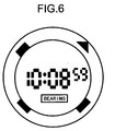
- Fig. 6 is a figure showing one example of a display panel used for the display circuit 14 of the electronic wrist watch with an bearing detector according to the present invention.
- the display panel is, for example, an LCD panel.
- the display panel of Fig. 6 has inner and outer two display areas divided by larger and smaller two circles.
- the inner display area has time display in a center and horizontal state display thereunder.
- the time display exhibits 10:8:59 and the horizontal state display is indicated by characters of BEARING within a box.
- the horizontal state display may be other display instead of BEARING.
- In the outer display region i.e.
- bearing marks of a triangular mark indicative of north and three square marks indicative of west, east and south are displayed with an equal interval on a circumference. It is natural the bearing marks can use other marks.
- bearing measurement could be automatically started by merely being positioned in a horizontal state the electronic wrist watch with an bearing detector. Accordingly, because bearing measurement is made in a horizontal state, i.e. in a state parallel with the ground, accuracy improvement was made for bearing measurement using an electronic wrist watch with an bearing detector. Also, because bearing measurement push button is not required to manually press upon starting measurement, the electronic wrist watch is easy for a wearer to utilize.
Landscapes
- Physics & Mathematics (AREA)
- General Physics & Mathematics (AREA)
- Electric Clocks (AREA)
Abstract
Description
Claims (4)
- An electronic wrist watch with an bearing detector comprising:a microprocessor,a memory storing a processing program; processing data and the like for the microprocessor;an oscillation circuit for providing a clock signal to the microprocessor;a display circuit driven by the microprocessor to perform time display,and bearing measurement value display; andan bearing detection circuit controlled by the microprocessor to perform bearing measurement; wherein when the horizontal detection circuit detects a horizontal state of the electronic wrist watch with an bearing detector, bearing measurement and bearing measurement value display are performed.
- An electronic wrist watch with an bearing detector according to claim 1, characterized in that bearing measurement started by detecting a horizontal state of the electronic wrist watch with an bearing detector by the horizontal detection circuit is continued until a measurement stop signal is inputted.
- An electronic wrist watch with an bearing detector according to claim 2, characterized in that the measurement stop signal is manually given by a push button.
- An electronic wrist watch with an bearing detector according to claim 2, characterized in that the measurement stop signal is given after elapsing a predetermined time period by a timer.
Applications Claiming Priority (2)
| Application Number | Priority Date | Filing Date | Title |
|---|---|---|---|
| JP6646999 | 1999-03-12 | ||
| JP11066469A JP2000258564A (en) | 1999-03-12 | 1999-03-12 | Electronic wristwatch with compass |
Publications (2)
| Publication Number | Publication Date |
|---|---|
| EP1041466A2 true EP1041466A2 (en) | 2000-10-04 |
| EP1041466A3 EP1041466A3 (en) | 2002-04-17 |
Family
ID=13316687
Family Applications (1)
| Application Number | Title | Priority Date | Filing Date |
|---|---|---|---|
| EP00301835A Withdrawn EP1041466A3 (en) | 1999-03-12 | 2000-03-07 | Electronic wrist watch with an bearing detector |
Country Status (3)
| Country | Link |
|---|---|
| US (1) | US6252824B1 (en) |
| EP (1) | EP1041466A3 (en) |
| JP (1) | JP2000258564A (en) |
Cited By (1)
| Publication number | Priority date | Publication date | Assignee | Title |
|---|---|---|---|---|
| WO2006104967A3 (en) * | 2005-03-25 | 2007-04-12 | Swiss Army Brands Inc | Timepiece having compass feature |
Families Citing this family (1)
| Publication number | Priority date | Publication date | Assignee | Title |
|---|---|---|---|---|
| KR20050073911A (en) * | 2004-01-12 | 2005-07-18 | 삼성전자주식회사 | Apparatus and method for adjusting time automatically of analog watch of analog watch built-in terminal |
Family Cites Families (9)
| Publication number | Priority date | Publication date | Assignee | Title |
|---|---|---|---|---|
| JPS5268464A (en) * | 1975-12-04 | 1977-06-07 | Seiko Instr & Electronics Ltd | Switch of electronic watches |
| US4117602A (en) * | 1977-04-04 | 1978-10-03 | The Laitram Corporation | Electromagnetic compass |
| US4337530A (en) * | 1980-05-27 | 1982-06-29 | Toft Jr Leonard L | Universal time-keeping system and apparatus |
| FR2515838A1 (en) * | 1981-10-30 | 1983-05-06 | Omega Brandt & Freres Sa Louis | CLOCKWARE HAVING AN ORIENTATION DEVICE |
| JP2935047B2 (en) * | 1990-03-13 | 1999-08-16 | カシオ計算機株式会社 | Electronic compass |
| US5216816A (en) * | 1990-03-20 | 1993-06-08 | Casio Computer Co., Ltd. | Compass |
| CH687288B5 (en) * | 1994-11-21 | 1997-05-15 | Asulab Sa | Watch comprising a detection device of the northbound earth magnetic. |
| US5600611A (en) * | 1995-10-04 | 1997-02-04 | Timex Corporation | Wrist mountable compass |
| CH691089A5 (en) * | 1997-05-14 | 2001-04-12 | Asulab Sa | timepiece associated with a compass and a viewfinder. |
-
1999
- 1999-03-12 JP JP11066469A patent/JP2000258564A/en active Pending
-
2000
- 2000-03-01 US US09/516,992 patent/US6252824B1/en not_active Expired - Lifetime
- 2000-03-07 EP EP00301835A patent/EP1041466A3/en not_active Withdrawn
Cited By (2)
| Publication number | Priority date | Publication date | Assignee | Title |
|---|---|---|---|---|
| WO2006104967A3 (en) * | 2005-03-25 | 2007-04-12 | Swiss Army Brands Inc | Timepiece having compass feature |
| US7778116B2 (en) | 2005-03-25 | 2010-08-17 | Swiss Army Brands, Inc. | Timepiece having compass feature |
Also Published As
| Publication number | Publication date |
|---|---|
| EP1041466A3 (en) | 2002-04-17 |
| JP2000258564A (en) | 2000-09-22 |
| US6252824B1 (en) | 2001-06-26 |
Similar Documents
| Publication | Publication Date | Title |
|---|---|---|
| US7532544B2 (en) | Multifunction timer device | |
| KR100843897B1 (en) | Means for loading or extracting data from a portable object, such as, in particular, a timepiece | |
| EP0268255A3 (en) | Stop watch | |
| WO2002014960A3 (en) | Electronic apparatus and method of controlling the electronic apparatus | |
| HK70389A (en) | Analog electronic timepiece | |
| US6252824B1 (en) | Electronic time piece with a bearing detector | |
| US6625087B2 (en) | Means for loading or extracting data from a portable object, such as, in particular, a timepiece | |
| HK1031437A (en) | Electronic wrist watch with an bearing detector | |
| GB2060954B (en) | Electronic timepiece | |
| JPS562583A (en) | Analog type chronograph watch | |
| WO1991006838A3 (en) | Electrical expiry indicator | |
| JPS56128480A (en) | Versatile wrist watch | |
| JP4293605B2 (en) | Clock device | |
| JPS5788377A (en) | Radio wave normalizing timepiece | |
| JPS57146185A (en) | Electronic wristwatch with accelometer | |
| JPS56147092A (en) | Watch processing method using microcomputer | |
| JPS55121184A (en) | Display means of electronic watch | |
| JPS54112682A (en) | Multifunctional electronic watch with bearing display | |
| JPS562581A (en) | Electronic watch | |
| JPS5412778A (en) | Digital display type electronic watch | |
| JPS57104886A (en) | Circuit for displaying morning and afternoon in electronic watch | |
| JPS5342774A (en) | Portable electronic watch | |
| JPS5458471A (en) | Electronic watch with alarm | |
| JPH05256960A (en) | Time measurement device | |
| JPS51140761A (en) | Multifunctional electronic clock device |
Legal Events
| Date | Code | Title | Description |
|---|---|---|---|
| PUAI | Public reference made under article 153(3) epc to a published international application that has entered the european phase |
Free format text: ORIGINAL CODE: 0009012 |
|
| AK | Designated contracting states |
Kind code of ref document: A2 Designated state(s): DE FR GB Kind code of ref document: A2 Designated state(s): AT BE CH CY DE DK ES FI FR GB GR IE IT LI LU MC NL PT SE |
|
| AX | Request for extension of the european patent |
Free format text: AL;LT;LV;MK;RO;SI |
|
| PUAL | Search report despatched |
Free format text: ORIGINAL CODE: 0009013 |
|
| AK | Designated contracting states |
Kind code of ref document: A3 Designated state(s): AT BE CH CY DE DK ES FI FR GB GR IE IT LI LU MC NL PT SE |
|
| AX | Request for extension of the european patent |
Free format text: AL;LT;LV;MK;RO;SI |
|
| RIC1 | Information provided on ipc code assigned before grant |
Free format text: 7G 04G 1/00 A, 7G 04C 3/00 B |
|
| 17P | Request for examination filed |
Effective date: 20021003 |
|
| AKX | Designation fees paid |
Free format text: DE FR GB |
|
| 17Q | First examination report despatched |
Effective date: 20050314 |
|
| STAA | Information on the status of an ep patent application or granted ep patent |
Free format text: STATUS: THE APPLICATION IS DEEMED TO BE WITHDRAWN |
|
| 18D | Application deemed to be withdrawn |
Effective date: 20050726 |
|
| REG | Reference to a national code |
Ref country code: HK Ref legal event code: WD Ref document number: 1031437 Country of ref document: HK |