EP1041333A2 - Trocken-Trennkupplung mit verbesserter Dichtung - Google Patents
Trocken-Trennkupplung mit verbesserter Dichtung Download PDFInfo
- Publication number
- EP1041333A2 EP1041333A2 EP00302742A EP00302742A EP1041333A2 EP 1041333 A2 EP1041333 A2 EP 1041333A2 EP 00302742 A EP00302742 A EP 00302742A EP 00302742 A EP00302742 A EP 00302742A EP 1041333 A2 EP1041333 A2 EP 1041333A2
- Authority
- EP
- European Patent Office
- Prior art keywords
- poppet
- coupler
- receptacle
- coupling
- face
- Prior art date
- Legal status (The legal status is an assumption and is not a legal conclusion. Google has not performed a legal analysis and makes no representation as to the accuracy of the status listed.)
- Withdrawn
Links
- 230000008878 coupling Effects 0.000 title claims abstract description 74
- 238000010168 coupling process Methods 0.000 title claims abstract description 74
- 238000005859 coupling reaction Methods 0.000 title claims abstract description 74
- 239000012530 fluid Substances 0.000 claims abstract description 36
- 238000007789 sealing Methods 0.000 claims abstract description 35
- 238000012546 transfer Methods 0.000 claims abstract description 8
- 239000007788 liquid Substances 0.000 claims description 22
- 230000013011 mating Effects 0.000 claims description 7
- 230000000717 retained effect Effects 0.000 claims description 7
- 230000007613 environmental effect Effects 0.000 claims description 5
- 230000002093 peripheral effect Effects 0.000 claims 1
- 210000003128 head Anatomy 0.000 description 24
- 210000001331 nose Anatomy 0.000 description 12
- 241000282472 Canis lupus familiaris Species 0.000 description 10
- 210000000887 face Anatomy 0.000 description 8
- 238000004519 manufacturing process Methods 0.000 description 4
- 238000000034 method Methods 0.000 description 4
- 238000006073 displacement reaction Methods 0.000 description 3
- 230000008901 benefit Effects 0.000 description 2
- 239000000463 material Substances 0.000 description 2
- 230000007246 mechanism Effects 0.000 description 2
- 238000009736 wetting Methods 0.000 description 2
- CWGBFIRHYJNILV-UHFFFAOYSA-N (1,4-diphenyl-1,2,4-triazol-4-ium-3-yl)-phenylazanide Chemical compound C=1C=CC=CC=1[N-]C1=NN(C=2C=CC=CC=2)C=[N+]1C1=CC=CC=C1 CWGBFIRHYJNILV-UHFFFAOYSA-N 0.000 description 1
- 239000004809 Teflon Substances 0.000 description 1
- 229920006362 Teflon® Polymers 0.000 description 1
- 230000003466 anti-cipated effect Effects 0.000 description 1
- 238000011109 contamination Methods 0.000 description 1
- 230000007812 deficiency Effects 0.000 description 1
- 239000000428 dust Substances 0.000 description 1
- 239000013536 elastomeric material Substances 0.000 description 1
- 238000005516 engineering process Methods 0.000 description 1
- NBVXSUQYWXRMNV-UHFFFAOYSA-N fluoromethane Chemical compound FC NBVXSUQYWXRMNV-UHFFFAOYSA-N 0.000 description 1
- 239000002828 fuel tank Substances 0.000 description 1
- 231100001261 hazardous Toxicity 0.000 description 1
- 230000003137 locomotive effect Effects 0.000 description 1
- 210000003141 lower extremity Anatomy 0.000 description 1
- 238000012423 maintenance Methods 0.000 description 1
- 239000003209 petroleum derivative Substances 0.000 description 1
- 239000012858 resilient material Substances 0.000 description 1
- 238000000926 separation method Methods 0.000 description 1
- 239000002689 soil Substances 0.000 description 1
- 238000012360 testing method Methods 0.000 description 1
Images


Classifications
-
- F—MECHANICAL ENGINEERING; LIGHTING; HEATING; WEAPONS; BLASTING
- F16—ENGINEERING ELEMENTS AND UNITS; GENERAL MEASURES FOR PRODUCING AND MAINTAINING EFFECTIVE FUNCTIONING OF MACHINES OR INSTALLATIONS; THERMAL INSULATION IN GENERAL
- F16L—PIPES; JOINTS OR FITTINGS FOR PIPES; SUPPORTS FOR PIPES, CABLES OR PROTECTIVE TUBING; MEANS FOR THERMAL INSULATION IN GENERAL
- F16L37/00—Couplings of the quick-acting type
- F16L37/28—Couplings of the quick-acting type with fluid cut-off means
- F16L37/30—Couplings of the quick-acting type with fluid cut-off means with fluid cut-off means in each of two pipe-end fittings
-
- Y—GENERAL TAGGING OF NEW TECHNOLOGICAL DEVELOPMENTS; GENERAL TAGGING OF CROSS-SECTIONAL TECHNOLOGIES SPANNING OVER SEVERAL SECTIONS OF THE IPC; TECHNICAL SUBJECTS COVERED BY FORMER USPC CROSS-REFERENCE ART COLLECTIONS [XRACs] AND DIGESTS
- Y10—TECHNICAL SUBJECTS COVERED BY FORMER USPC
- Y10T—TECHNICAL SUBJECTS COVERED BY FORMER US CLASSIFICATION
- Y10T137/00—Fluid handling
- Y10T137/8593—Systems
- Y10T137/87917—Flow path with serial valves and/or closures
- Y10T137/87925—Separable flow path section, valve or closure in each
-
- Y—GENERAL TAGGING OF NEW TECHNOLOGICAL DEVELOPMENTS; GENERAL TAGGING OF CROSS-SECTIONAL TECHNOLOGIES SPANNING OVER SEVERAL SECTIONS OF THE IPC; TECHNICAL SUBJECTS COVERED BY FORMER USPC CROSS-REFERENCE ART COLLECTIONS [XRACs] AND DIGESTS
- Y10—TECHNICAL SUBJECTS COVERED BY FORMER USPC
- Y10T—TECHNICAL SUBJECTS COVERED BY FORMER US CLASSIFICATION
- Y10T137/00—Fluid handling
- Y10T137/8593—Systems
- Y10T137/87917—Flow path with serial valves and/or closures
- Y10T137/87925—Separable flow path section, valve or closure in each
- Y10T137/87973—Coupling interlocked with valve, or closure or actuator
Definitions
- the present invention relates to improvements in dry disconnect couplings.
- Dry disconnect couplings also commonly called dry-break couplings, are used in various applications to connect one fluid conduit to another to form a continuous flow path.
- dry disconnect couplings comprise a receptacle and a coupler.
- the receptacle may be mounted on a fluid conduit, or may form the inlet to, or outlet from, a fluid container such as a storage tank.
- the coupler may be mounted on a fluid conduit and means are provided for mechanically locking the coupler and receptacle together to provide an environmentally sealed connection for the transfer of fluids.
- the receptacle and coupler each have a flow passageway, which is sealed by a poppet valve when the coupling is uncoupled.
- the poppets When the coupler is locked on to the receptacle, the poppets are displaced from their seats to permit flow of fluid through the coupling.
- Mechanical interlocks are provided to prevent separation of the two components unless the poppets are returned to their closed position.
- the primary source of spillage is the liquid remaining in the annular space between the periphery of the poppets and the circumferential seal between the coupler and the receptacle, when the poppets are retracted to the closed position.
- a secondary source of spillage is liquid, which may enter into the space between the opposed faces of the poppets when they are displaced in the open position and which remains there when the poppets are retracted. This space is the result of misalignment between the poppet faces, manufacturing imperfections, or damage to the poppet faces, or a combination of these causes.
- Oberrecht provides an O-ring mounted in a groove formed in the face of the coupler poppet which forms a seal against the face of the receptacle poppet to prevent the interface being wetted when the poppets are in the open position. Liquid residue may still remain around the periphery of this seal. Oberrecht also reveals an alternative method in which a sealing ring of rectangular cross section is bonded to the face of the coupler poppet with the purpose of minimizing the annular gap around the periphery of the poppet. The cross section of this seal is much less resilient than the O-ring and is less suitable for the function desired. Furthermore, being bonded in place, it is difficult to replace when this becomes necessary. Roberts accepts the aforementioned deficiencies and provides a reservoir to collect any spillage and a means to return it to the flow path. It will be noted that this return flow is induced by the passage of liquid through the coupling and ceases when the poppets are closed.
- the present invention provides a dry disconnect coupling for connecting one fluid conduit to another fluid conduit to form a continuous flow path, said coupling comprising a receptacle and a coupler, each being secured to a respective conduit or container, with means for securing and locking the receptacle and the coupler together to provide a connection for transfer of fluids,
- the coupler has resilient sealing means around the periphery of the interface between the coupler and the receptacle which comprises a resilient annular seal in the end face of a sleeve located within the coupler body and two additional resilient annular seals provided between the coupler body and the sleeve and between the sleeve and the coupler poppet, respectively, to contain fluid under pressure; and
- the coupling of the present invention provides a dry disconnect coupling in which spillage of liquid is minimized by a) providing an effective method of preventing the wetting of the entirety of the poppet faces and b) reducing the annular space around the periphery of the poppet seals to a minimum.
- An additional advantage of the coupling of the present invention is that maintenance and replacement of the coupler poppet head and seal are easily accomplished without the need to remove internal fluid pressure from the coupler.
- the present coupling includes means for mechanically locking the two components together before and during fluid transfer using technology known in the art.
- the receptacle is sealed by a spring loaded poppet, the poppet having a frusto-conical sealing surface which is seated on a matching frusto-conical seat in the receptacle body.
- Other suitable shapes may be selected for the sealing surfaces.
- the effectiveness of the sealing arrangement just described is increased by resilient sealing means, for example, an O-ring which resides in a groove in the poppet sealing surface.
- the geometry of the receptacle poppet and body are such that the face of the poppet is flush with the adjacent face of the body when the poppet is in the closed position.
- the coupler incorporates resilient sealing means that preferably comprises an O-ring which provides an environmental seal around the periphery of the interface between the coupler and receptacle when the two are conjoined and locked together in condition for fluid transfer.
- This face seal is preferably carried in a groove in the end face of a sleeve within the body of the coupler, the face seal sleeve being spring-loaded to force the seal against a corresponding face on the receptacle body.
- Two additional adjacent, annular seals, preferably O-ring seals are used to seal between the coupler body and the face seal sleeve and between the face seal sleeve and the coupler poppet to contain liquid under pressure.
- a mating portion for example a shoulder on the poppet body engages a corresponding mating portion, for example a corresponding register on the face seal sleeve and causes the sleeve to retract slightly thus disengaging the face O-ring seal from its contact with the receptacle.
- a small clearance between the two poppets which is provided so that engagement between the coupler and the receptacle may take place without mechanical interference between the poppets as a result of dimensional discrepancies among the various components.
- self-alignment of the coupler poppet is achieved as follows.
- the face of the coupler poppet is not rigidly attached to the poppet body but is freely located in a recess in the end of the poppet body and is loosely retained by means of a screw on the axial centreline so that the poppet head can move axially and may tilt in any direction to align itself with the receptacle poppet when the two poppets come into contact.
- the surface of the poppet head is extended circumferentially to form a small flange which acts to retain an O-ring against the main body of the poppet.
- the geometry of the components is such that the outside diameter of the O-ring is approximately the same as the diameter of the poppet body and the face of the O-ring is slightly proud of the surface of the poppet head. Consequently, when the coupler poppet is pressed against the face of the receptacle poppet, the coupler poppet head tilts to align face-to-face with the receptacle poppet and at the same time the O-ring is compressed between the coupler poppet body and the receptacle poppet. By this means, any intrusion of liquid between the two poppet faces is prevented.
- resilient sealing means may be made from the same suitably resilient material, examples of which include VitonTM, BUNA NTM, a nitron or fluorocarbon material.
- the coupler mechanism is activated causing the coupler poppet to extend and this in turn allows the face seal sleeve spring to force the sleeve to extend until the face seal is forcibly pressed against the face of the receptacle thus effecting an environmental seal against leakage of liquid from within the coupling.
- the coupler poppet head seal is compressed against the receptacle poppet as described earlier. Further extension of the coupler poppet causes the receptacle poppet to open simultaneously until the coupling is fully open.
- the theoretical volume of the interspace is approximately .26 cubic centimeters. In practice, allowing for manufacturing tolerances, misalignment of the coupling members, etc., a spillage of not more than 1 cubic centimeter is anticipated.
- coupler poppet head seal and the poppet head in addition to the coupler face seal, can be maintained or replaced without the need to remove internal fluid pressure from the coupler.
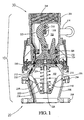
- FIG. 1 is a sectional view of a dry disconnect coupling according to the invention showing the coupler connected to the receptacle and the poppets of the coupler and the receptacle closed.
- FIG. 2 is a sectional view of the coupler of the coupling of FIG. 1 taken in a plane normal to the plane of FIG. 1 showing the coupler in its disconnected state.
- FIG. 3 is an end elevational view of the coupler of FIG. 2 taken from the proximate side of FIG. 2.
- FIG. 4 is a fragmentary sectional view taken on line 4 - 4 in FIG. 2
- FIG. 5 is a sectional view of a dry disconnect coupling according to the invention showing the coupler connected to the receptacle and the poppets of the coupler and the receptacle fully open.
- FIG. 6 is a fragmentary sectional view at an enlarged scale of a coupler poppet and a receptacle poppet and seals employed in the coupling of FIG. 1
- FIG. 7 is a fragmentary sectional view at an enlarged scale of the poppets and seals of FIG. 6 with the coupler poppet extended to make contact with the receptacle poppet.
- FIG. 8 is a fragmentary sectional view at an enlarged scale of the poppets and seals of FIG. 6 with the coupler poppet and the receptacle poppet displaced to partially open the coupling of FIG. 1.
- FIG. 9 is a fragmentary sectional view at a much enlarged scale of a coupler poppet and seal employed in the coupler of FIG. 2.
- FIG. 1 illustrates a dry disconnect coupling according to the invention, indicated generally at 10.
- the coupling comprises two separable components, a receptacle indicated generally at 20 and a coupler indicated generally at 30.
- the receptacle comprises a generally cylindrical body, 201 defining a flow passageway 202 therethrough.
- Body 201 comprises a flange 204 for attaching one end of the body to a body extension 206 which in turn comprises a flange 208 for attaching the receptacle to the end of a fluid conduit (not shown), or preferably to the inlet of a vehicle fuel tank (not shown).
- the other end of body 201 comprises an annular flange 210 for attaching the coupler 30 to the receptacle 20.
- Receptacle 20 further comprises a poppet valve 212 for sealing the flow passageway 202.
- Poppet 212 comprises a frusto-conical sealing surface 214 biased by a spring 218 against a mating frusto-conical surface 216 at the end of the receptacle 20.
- An O-ring seal 220 seals surface 214 and surface 216 when the poppet valve 212 is closed.
- O-ring 220 typically, is preferably formed of a resilient elastomeric material which is not degraded by petroleum products or other liquids which may flow through the coupling when in service.
- Poppet 212 further comprises a cylindrical guide rod 222 which is threadably attached to a hub 224 forming part of poppet 212 and is axially concentric with poppet 212.
- Guide rod 222 is slidably engaged with a hub 226 which comprises a frusto-conical extension 236 and a plurality of radial ribs 228 that are secured to the interior of body 201 by means of retaining ring 230.
- poppet valve 212 When poppet valve 212 is fully open (FIG. 5) the posterior surface 238 of poppet 212 is in close proximity to the end 240 of hub extension 236 so that the alignment of poppet surface 214 and the exterior surface of hub extension 236 define a profile resulting in low resistance to flow of liquid through the receptacle.
- Coupler 30 further comprises a poppet valve 306 for sealing the flow passageway and a poppet actuating mechanism comprising lever 314, shaft 316, cranks 318 and link 320.
- Shaft 316 is journaled on coupler body 301by means of bearings 315 and 317.
- O-ring seals 319 and 321 seal shaft 316 and body 301.
- Shaft 316 is retained in body 301 by hairclip clip 323 which resides in a groove in shaft 316.
- Lever 314 and cranks 318 are mounted in locked angular relationship on shaft 316.
- One end of link 320 is pivotally connected between cranks 318 by means of pin 322 and the other end of link 320 is pivotally connected to poppet 306 by means of pin 344 so that rotation of lever 314 actuates poppet 306 from its closed position to its fully open position, and subsequent reverse rotation of lever 314 retracts poppet 306 to its closed position.
- An annular nose seal ring 308 is interposed between poppet 306 and the inner surface of body 301.
- O-ring seal 328 seals ring 308 and body 301.
- Poppet 306 has three longitudinal guide arms 326 which engage the inner surface of nose seal ring 308 to guide the poppet throughout its axial movement relative to the passageway 302. Nose seal ring 308 is biased by a wave spring 310 against a shoulder 312 on poppet 306 such that ring 308 moves with the poppet relative to body 301.
- the poppet and nose seal ring 308 are sealed by O-ring 330.
- Poppet 306 comprises poppet body 358 and poppet head 352.
- Poppet head 352 is slidably retained in a recess in poppet body 358 by shoulder screw 354, the proportions of the parts being such that a clearance, typically of the order of 0.020 inches, remains between the back surface of poppet head 352 and the adjacent surface of poppet body 358.
- the clearances between poppet head 352, poppet body 358 and shoulder screw 354 allow poppet head 352 to tilt slightly when subject to external forces.
- Reference to FIG. 6 and FIG. 9 clearly reveals the geometric relationship between the poppet components.
- O-ring 356 is retained between annular projecting lip 360 on poppet body 358 and annular projecting lip 362 on poppet head 352 and, due to its resilient properties, forces poppet head 352 to be seated against the shoulder of shoulder screw 354.
- O-ring 364 is retained in an annular groove 368 concentric with the coupler axis to form a face seal on the end face of nose seal ring 308.
- the thickness of the annular wall between groove 368 and the inner face 370 (FIG. 8) is typically of the order of 0.040 in. and as is apparent from reference to FIG. 6, when the poppet valve 306 is closed, the proximity of O-ring seals 330, 356 and 364 is as close as may be achieved by normal manufacturing methods.
- Body 301 further comprises, at its lower extremity a plurality of out-turned brackets 342 (FIG. 4), disposed in pairs which are spaced equidistant around the circumference of body 301.
- Each pair of brackets 342 is drilled in line to accommodate a pivot pin 344.
- a latching dog 346 is pivotally mounted on pivot pin 344.
- an annular latch sleeve 332 comprises an inturned flange 334 which limits travel of sleeve 332 between body flange 336 and cam 338, the latter being mounted on shaft 316 in locked angular relationship with lever 314 and cranks 318.
- a dust seal 340 preferably made of teflon or similar material with low friction properties, is retained in a groove in flange 334 and seals sleeve 332 and body 301.
- An annular groove 348 is machined on the inner surface of sleeve 332 in a location such that when sleeve 332 is fully retracted, each latching dog 346 is urged by a torsion spring 350 to engage in groove 348 thereby preventing displacement of sleeve 332 from its retracted position when coupler 30 is not engaged with receptacle 20.
- shaft 316 is prevented from rotation as a result of the proximity of cam 338 and sleeve 332.
- FIG. 6 as has been previously described, the poppets of the receptacle and coupler are shown in the closed state corresponding to that of FIG. 1 in which coupler 30 and receptacle 20 are coupled and locked together.
- the coupler is disengaged from the receptacle by following a reverse procedure to that previously described for coupling them.
- Lever 314 is rotated from its open position as shown in FIG. 5 to its closed position as shown in FIG. 1.
- the resulting rotation of shaft 316 and crank 318 displaces link 320 thus causing poppet 306 to travel axially to its closed position as shown in FIG. 1 and FIG. 6.
- receptacle poppet 212 is urged by spring 218 to maintain contact with coupler poppet 306 until poppet surface 214 contacts receptacle body surface 216 and the surfaces are sealed by O-ring 220.
- cam 338 is disposed as shown in FIG.
- latch sleeve 332 When latch sleeve 332 is fully retracted, torsion springs 350 urge latch dogs 346 to rotate on pivot pins 344 and consequently, to snap into groove 348 (FIG. 4), thus preventing further axial movement of latch sleeve 332. Further, the rotation of latch dogs 346 causes latch dog faces 366 to move away from the back face of receptacle flange 210, thus unlocking the coupling and allowing coupler 30 to be withdrawn from contact with receptacle 20.
- the volume of liquid which resides in the annular interspace between O-rings 220, 330, 356 and 364 under the condition shown in FIG. 7 is the amount of liquid which may escape during uncoupling of the coupler and receptacle.
Landscapes
- Engineering & Computer Science (AREA)
- General Engineering & Computer Science (AREA)
- Mechanical Engineering (AREA)
- Quick-Acting Or Multi-Walled Pipe Joints (AREA)
Applications Claiming Priority (2)
| Application Number | Priority Date | Filing Date | Title |
|---|---|---|---|
| US285467 | 1988-12-16 | ||
| US09/285,467 US6155294A (en) | 1999-04-02 | 1999-04-02 | Dry disconnect coupling with improved poppet seal |
Publications (2)
| Publication Number | Publication Date |
|---|---|
| EP1041333A2 true EP1041333A2 (de) | 2000-10-04 |
| EP1041333A3 EP1041333A3 (de) | 2002-08-14 |
Family
ID=23094360
Family Applications (1)
| Application Number | Title | Priority Date | Filing Date |
|---|---|---|---|
| EP00302742A Withdrawn EP1041333A3 (de) | 1999-04-02 | 2000-03-31 | Trocken-Trennkupplung mit verbesserter Dichtung |
Country Status (3)
| Country | Link |
|---|---|
| US (1) | US6155294A (de) |
| EP (1) | EP1041333A3 (de) |
| CA (1) | CA2302789A1 (de) |
Cited By (2)
| Publication number | Priority date | Publication date | Assignee | Title |
|---|---|---|---|---|
| ITBO20080585A1 (it) * | 2008-09-26 | 2010-03-27 | Gima Spa | Dispositivo e metodo per regolare e miscelare un fluido attivo in un fluido da trattare |
| WO2010048134A1 (en) * | 2008-10-21 | 2010-04-29 | OPW Engineered Systems | Handle shaft assemblies for bottom loading couplers |
Families Citing this family (47)
| Publication number | Priority date | Publication date | Assignee | Title |
|---|---|---|---|---|
| US7878219B2 (en) * | 2000-07-28 | 2011-02-01 | Hiltap Fittings, Ltd. | Fluid system coupling with pin lock |
| US6672327B1 (en) * | 2000-07-28 | 2004-01-06 | Hiltap Fittings, Ltd. | Dry break valve assembly |
| US6981513B2 (en) * | 2000-07-28 | 2006-01-03 | Hiltap Fittings, Ltd | Fluid flow management system |
| US7152630B2 (en) * | 2000-07-28 | 2006-12-26 | Hiltap Fittings, Ltd. | Fluid system coupling |
| US7909365B2 (en) * | 2000-07-28 | 2011-03-22 | Hiltap Fittings, Ltd. | Fluid system coupling with handle actuating member |
| US8225809B2 (en) | 2000-07-28 | 2012-07-24 | Hiltap Fittings, Ltd. | Methods and apparatus for introducing a pig into a fluid system |
| US6298876B1 (en) | 2001-05-02 | 2001-10-09 | Ozone Industries, Inc. | Quick disconnect coupling |
| US6688650B2 (en) * | 2001-12-04 | 2004-02-10 | Sun Microsystems, Inc. | Dry disconnect fluidic coupling |
| US6945477B2 (en) * | 2002-09-04 | 2005-09-20 | Parker-Hannifin Corporation | Cryogenic coupling device |
| US20050061366A1 (en) * | 2003-06-09 | 2005-03-24 | Rademacher John L. | Dual stop valve assembly for use in cargo tank vehicles |
| US20060027262A1 (en) * | 2003-06-09 | 2006-02-09 | Rademacher John L | Dual stop valve assembly for use in cargo tank vehicles |
| IL163624A (en) * | 2003-08-29 | 2007-06-03 | Triumph Brands Inc | Quick disconnect with retaining spring |
| US7117892B2 (en) * | 2003-10-24 | 2006-10-10 | Hiltap Fittings, Ltd. | Quick disconnect valve assembly |
| US6932123B1 (en) | 2004-07-19 | 2005-08-23 | Marathon Ashland Petroluem Llc | Drop tube assembly |
| US7575024B2 (en) | 2005-11-05 | 2009-08-18 | Snap-Tite Technologies, Inc. | Threaded coupling with flow shutoff |
| US7762279B2 (en) | 2005-11-05 | 2010-07-27 | Snap-Tite Technologies, Inc. | Threaded coupling with flow shutoff |
| US7988200B2 (en) * | 2008-07-21 | 2011-08-02 | Hiltap Fittings, Ltd. | Fluid system coupling with pivoting handle actuating member |
| US8113240B2 (en) * | 2008-08-01 | 2012-02-14 | Marshall Excelsior Company | Low emission fluid transfer device |
| US8336853B2 (en) * | 2009-07-17 | 2012-12-25 | Delaware Capital Formation, Inc. | Recock handle assemblies for coupler devices and coupler devices comprising the same |
| CN103270362B (zh) | 2010-08-10 | 2015-11-25 | 霍华德·M·小西 | 快速连接的联接器 |
| US8454059B2 (en) * | 2010-09-13 | 2013-06-04 | Pall Corporation | Connector assemblies, fluid systems including connector assemblies, and procedures for making fluid connections |
| ES2983067T3 (es) * | 2011-03-21 | 2024-10-21 | Engineered Controls Int Llc | Acoplador de conexión rápida con parada de evacuación |
| EP3289269B1 (de) | 2015-04-27 | 2021-12-22 | Engineered Controls International, LLC | Schnellverbindungskoppler mit entlüftungsanschlag |
| EP4290120A3 (de) | 2015-12-03 | 2024-04-17 | Engineered Controls International, LLC | Emissionsarme düsen und behälter |
| US10563773B2 (en) * | 2016-05-20 | 2020-02-18 | Opw-Engineered Systems, Inc. | Fluid system coupling with internal valves |
| US10696906B2 (en) | 2017-09-29 | 2020-06-30 | Marathon Petroleum Company Lp | Tower bottoms coke catching device |
| US12000720B2 (en) | 2018-09-10 | 2024-06-04 | Marathon Petroleum Company Lp | Product inventory monitoring |
| US12031676B2 (en) | 2019-03-25 | 2024-07-09 | Marathon Petroleum Company Lp | Insulation securement system and associated methods |
| ES3054061T3 (en) | 2019-04-05 | 2026-01-29 | Engineered Controls Int Llc | Coupler having anti-rotation feature |
| US11975316B2 (en) | 2019-05-09 | 2024-05-07 | Marathon Petroleum Company Lp | Methods and reforming systems for re-dispersing platinum on reforming catalyst |
| CA3212048A1 (en) | 2019-05-30 | 2020-11-30 | Marathon Petroleum Company Lp | Methods and systems for minimizing nox and co emissions in natural draft heaters |
| CA3109606C (en) | 2020-02-19 | 2022-12-06 | Marathon Petroleum Company Lp | Low sulfur fuel oil blends for paraffinic resid stability and associated methods |
| US11898109B2 (en) | 2021-02-25 | 2024-02-13 | Marathon Petroleum Company Lp | Assemblies and methods for enhancing control of hydrotreating and fluid catalytic cracking (FCC) processes using spectroscopic analyzers |
| US20250012744A1 (en) | 2021-02-25 | 2025-01-09 | Marathon Petroleum Company Lp | Methods and assemblies for enhancing control of refining processes using spectroscopic analyzers |
| US12473500B2 (en) | 2021-02-25 | 2025-11-18 | Marathon Petroleum Company Lp | Assemblies and methods for enhancing control of fluid catalytic cracking (FCC) processes using spectroscopic analyzers |
| US11702600B2 (en) | 2021-02-25 | 2023-07-18 | Marathon Petroleum Company Lp | Assemblies and methods for enhancing fluid catalytic cracking (FCC) processes during the FCC process using spectroscopic analyzers |
| US12461022B2 (en) | 2021-02-25 | 2025-11-04 | Marathon Petroleum Company Lp | Methods and assemblies for determining and using standardized spectral responses for calibration of spectroscopic analyzers |
| US11905468B2 (en) | 2021-02-25 | 2024-02-20 | Marathon Petroleum Company Lp | Assemblies and methods for enhancing control of fluid catalytic cracking (FCC) processes using spectroscopic analyzers |
| US11692141B2 (en) | 2021-10-10 | 2023-07-04 | Marathon Petroleum Company Lp | Methods and systems for enhancing processing of hydrocarbons in a fluid catalytic cracking unit using a renewable additive |
| US11802257B2 (en) | 2022-01-31 | 2023-10-31 | Marathon Petroleum Company Lp | Systems and methods for reducing rendered fats pour point |
| US12311305B2 (en) | 2022-12-08 | 2025-05-27 | Marathon Petroleum Company Lp | Removable flue gas strainer and associated methods |
| CA3238046A1 (en) | 2023-05-12 | 2025-07-07 | Marathon Petroleum Company Lp | Systems, apparatuses, and methods for sample cylinder inspection, pressurization, and sample disposal |
| US12533615B2 (en) | 2023-06-02 | 2026-01-27 | Marathon Petroleum Company Lp | Methods and systems for reducing contaminants in a feed stream |
| CN116817058B (zh) * | 2023-06-13 | 2024-08-30 | 广东泰恩流体控制设备有限公司 | 一种管道连接器 |
| CN116986162A (zh) * | 2023-08-24 | 2023-11-03 | 中集安瑞环科技股份有限公司 | 阀件及罐式集装箱 |
| US12415962B2 (en) | 2023-11-10 | 2025-09-16 | Marathon Petroleum Company Lp | Systems and methods for producing aviation fuel |
| US12599848B2 (en) | 2024-06-03 | 2026-04-14 | Marathon Petroleum Company Lp | Systems, analyzers, controllers, and associated methods to enhance fluid separation for distillation operations |
Citations (2)
| Publication number | Priority date | Publication date | Assignee | Title |
|---|---|---|---|---|
| US5273071A (en) | 1992-03-05 | 1993-12-28 | Dover Corporation | Dry disconnect couplings |
| US5628344A (en) | 1995-05-17 | 1997-05-13 | Emco Wheaton, Inc. | Dry disconnect coupling including means for returning fluid residue to flow path |
Family Cites Families (5)
| Publication number | Priority date | Publication date | Assignee | Title |
|---|---|---|---|---|
| US3910312A (en) * | 1974-04-22 | 1975-10-07 | Karl Weinhold | Coupling for pressure conduits |
| DE3621951A1 (de) * | 1986-06-30 | 1988-01-21 | Hubert Skibowski | Vollschlauchsystemkupplung |
| US5404909A (en) * | 1992-06-11 | 1995-04-11 | Parker-Hannifin Corporation | Coupling device |
| US5433247A (en) * | 1994-08-05 | 1995-07-18 | Catlow, Inc. | Coaxial breakaway coupling with vapor assist check |
| US5709243A (en) * | 1995-11-20 | 1998-01-20 | Aeroquip Corporation | Low spill female coupling |
-
1999
- 1999-04-02 US US09/285,467 patent/US6155294A/en not_active Expired - Fee Related
-
2000
- 2000-03-28 CA CA002302789A patent/CA2302789A1/en not_active Abandoned
- 2000-03-31 EP EP00302742A patent/EP1041333A3/de not_active Withdrawn
Patent Citations (2)
| Publication number | Priority date | Publication date | Assignee | Title |
|---|---|---|---|---|
| US5273071A (en) | 1992-03-05 | 1993-12-28 | Dover Corporation | Dry disconnect couplings |
| US5628344A (en) | 1995-05-17 | 1997-05-13 | Emco Wheaton, Inc. | Dry disconnect coupling including means for returning fluid residue to flow path |
Cited By (3)
| Publication number | Priority date | Publication date | Assignee | Title |
|---|---|---|---|---|
| ITBO20080585A1 (it) * | 2008-09-26 | 2010-03-27 | Gima Spa | Dispositivo e metodo per regolare e miscelare un fluido attivo in un fluido da trattare |
| WO2010048134A1 (en) * | 2008-10-21 | 2010-04-29 | OPW Engineered Systems | Handle shaft assemblies for bottom loading couplers |
| US8302628B2 (en) | 2008-10-21 | 2012-11-06 | Delaware Capital Formation, Inc. | Handle shaft assemblies for bottom loading couplers |
Also Published As
| Publication number | Publication date |
|---|---|
| US6155294A (en) | 2000-12-05 |
| CA2302789A1 (en) | 2000-10-02 |
| EP1041333A3 (de) | 2002-08-14 |
Similar Documents
| Publication | Publication Date | Title |
|---|---|---|
| US6155294A (en) | Dry disconnect coupling with improved poppet seal | |
| US5273071A (en) | Dry disconnect couplings | |
| US4768538A (en) | Radial seal hydraulic coupler | |
| US20120090713A1 (en) | Grease delivery receiver and nozzle couplable without fluid pressure bleed-down and having pressurization lockout and flush face coupling | |
| US3706318A (en) | Fluid coupling | |
| US5115836A (en) | Breakaway hose coupling with integrated swivel mechanism | |
| CA2137825A1 (en) | Coupling device | |
| CA2019227A1 (en) | Valved quick connect/disconnect coupling | |
| AU2012325814A1 (en) | Grease delivery receiver and nozzle having pressurization lockout and bleed-down capture | |
| US5255699A (en) | Nipple with integral crossbar actuator and check valve | |
| WO1994013990A1 (en) | Push-to-connect coupler with interlocking three-way valve | |
| US6009901A (en) | Dry disconnect coupling | |
| EP1166002B1 (de) | Druckausgeglichene kupplung mit druckablass | |
| US5191914A (en) | Redundant valve disconnect coupling | |
| US4289295A (en) | Self-sealing connector | |
| CA2033571C (en) | Dry break pipe coupling | |
| US6505861B2 (en) | Rotatable swivel elbow | |
| CA2674159A1 (en) | Coupling assembly with check valve actuator | |
| CA2967673C (en) | Valved coupler | |
| US2972491A (en) | Hydraulic quick disconnect | |
| US4989638A (en) | Substantially leak-free disconnection apparatus | |
| US3432191A (en) | Separable coupling | |
| AU2009307773B2 (en) | Handle shaft assemblies for bottom loading couplers | |
| US2983526A (en) | Self sealing pipe coupling | |
| US8042571B2 (en) | Rigid mount anti-leak fluid coupler |
Legal Events
| Date | Code | Title | Description |
|---|---|---|---|
| PUAI | Public reference made under article 153(3) epc to a published international application that has entered the european phase |
Free format text: ORIGINAL CODE: 0009012 |
|
| AK | Designated contracting states |
Kind code of ref document: A2 Designated state(s): AT BE CH CY DE DK ES FI FR GB GR IE IT LI LU MC NL PT SE |
|
| AX | Request for extension of the european patent |
Free format text: AL;LT;LV;MK;RO;SI |
|
| PUAL | Search report despatched |
Free format text: ORIGINAL CODE: 0009013 |
|
| AK | Designated contracting states |
Kind code of ref document: A3 Designated state(s): AT BE CH CY DE DK ES FI FR GB GR IE IT LI LU MC NL PT SE |
|
| AX | Request for extension of the european patent |
Free format text: AL;LT;LV;MK;RO;SI |
|
| AKX | Designation fees paid | ||
| REG | Reference to a national code |
Ref country code: DE Ref legal event code: 8566 |
|
| STAA | Information on the status of an ep patent application or granted ep patent |
Free format text: STATUS: THE APPLICATION IS DEEMED TO BE WITHDRAWN |
|
| 18D | Application deemed to be withdrawn |
Effective date: 20030215 |