EP1041320A2 - Improvements in pumps - Google Patents
Improvements in pumps Download PDFInfo
- Publication number
- EP1041320A2 EP1041320A2 EP00302554A EP00302554A EP1041320A2 EP 1041320 A2 EP1041320 A2 EP 1041320A2 EP 00302554 A EP00302554 A EP 00302554A EP 00302554 A EP00302554 A EP 00302554A EP 1041320 A2 EP1041320 A2 EP 1041320A2
- Authority
- EP
- European Patent Office
- Prior art keywords
- fluid
- seal
- pump
- shroud
- chamber
- Prior art date
- Legal status (The legal status is an assumption and is not a legal conclusion. Google has not performed a legal analysis and makes no representation as to the accuracy of the status listed.)
- Granted
Links
Images


Classifications
-
- H—ELECTRICITY
- H01—ELECTRIC ELEMENTS
- H01R—ELECTRICALLY-CONDUCTIVE CONNECTIONS; STRUCTURAL ASSOCIATIONS OF A PLURALITY OF MUTUALLY-INSULATED ELECTRICAL CONNECTING ELEMENTS; COUPLING DEVICES; CURRENT COLLECTORS
- H01R31/00—Coupling parts supported only by co-operation with counterpart
- H01R31/06—Intermediate parts for linking two coupling parts, e.g. adapter
-
- F—MECHANICAL ENGINEERING; LIGHTING; HEATING; WEAPONS; BLASTING
- F16—ENGINEERING ELEMENTS AND UNITS; GENERAL MEASURES FOR PRODUCING AND MAINTAINING EFFECTIVE FUNCTIONING OF MACHINES OR INSTALLATIONS; THERMAL INSULATION IN GENERAL
- F16J—PISTONS; CYLINDERS; SEALINGS
- F16J15/00—Sealings
- F16J15/16—Sealings between relatively-moving surfaces
- F16J15/34—Sealings between relatively-moving surfaces with slip-ring pressed against a more or less radial face on one member
- F16J15/3404—Sealings between relatively-moving surfaces with slip-ring pressed against a more or less radial face on one member and characterised by parts or details relating to lubrication, cooling or venting of the seal
-
- F—MECHANICAL ENGINEERING; LIGHTING; HEATING; WEAPONS; BLASTING
- F04—POSITIVE - DISPLACEMENT MACHINES FOR LIQUIDS; PUMPS FOR LIQUIDS OR ELASTIC FLUIDS
- F04D—NON-POSITIVE-DISPLACEMENT PUMPS
- F04D29/00—Details, component parts, or accessories
- F04D29/08—Sealings
- F04D29/10—Shaft sealings
- F04D29/12—Shaft sealings using sealing-rings
- F04D29/126—Shaft sealings using sealing-rings especially adapted for liquid pumps
- F04D29/128—Shaft sealings using sealing-rings especially adapted for liquid pumps with special means for adducting cooling or sealing fluid
-
- F—MECHANICAL ENGINEERING; LIGHTING; HEATING; WEAPONS; BLASTING
- F04—POSITIVE - DISPLACEMENT MACHINES FOR LIQUIDS; PUMPS FOR LIQUIDS OR ELASTIC FLUIDS
- F04D—NON-POSITIVE-DISPLACEMENT PUMPS
- F04D29/00—Details, component parts, or accessories
- F04D29/40—Casings; Connections of working fluid
- F04D29/42—Casings; Connections of working fluid for radial or helico-centrifugal pumps
- F04D29/426—Casings; Connections of working fluid for radial or helico-centrifugal pumps especially adapted for liquid pumps
-
- H—ELECTRICITY
- H01—ELECTRIC ELEMENTS
- H01R—ELECTRICALLY-CONDUCTIVE CONNECTIONS; STRUCTURAL ASSOCIATIONS OF A PLURALITY OF MUTUALLY-INSULATED ELECTRICAL CONNECTING ELEMENTS; COUPLING DEVICES; CURRENT COLLECTORS
- H01R24/00—Two-part coupling devices, or either of their cooperating parts, characterised by their overall structure
- H01R24/60—Contacts spaced along planar side wall transverse to longitudinal axis of engagement
-
- H—ELECTRICITY
- H04—ELECTRIC COMMUNICATION TECHNIQUE
- H04M—TELEPHONIC COMMUNICATION
- H04M1/00—Substation equipment, e.g. for use by subscribers
- H04M1/02—Constructional features of telephone sets
- H04M1/0202—Portable telephone sets, e.g. cordless phones, mobile phones or bar type handsets
- H04M1/026—Details of the structure or mounting of specific components
- H04M1/0274—Details of the structure or mounting of specific components for an electrical connector module
-
- H—ELECTRICITY
- H01—ELECTRIC ELEMENTS
- H01R—ELECTRICALLY-CONDUCTIVE CONNECTIONS; STRUCTURAL ASSOCIATIONS OF A PLURALITY OF MUTUALLY-INSULATED ELECTRICAL CONNECTING ELEMENTS; COUPLING DEVICES; CURRENT COLLECTORS
- H01R2201/00—Connectors or connections adapted for particular applications
- H01R2201/16—Connectors or connections adapted for particular applications for telephony
-
- H—ELECTRICITY
- H02—GENERATION; CONVERSION OR DISTRIBUTION OF ELECTRIC POWER
- H02J—CIRCUIT ARRANGEMENTS OR SYSTEMS FOR SUPPLYING OR DISTRIBUTING ELECTRIC POWER; SYSTEMS FOR STORING ELECTRIC ENERGY
- H02J7/00—Circuit arrangements for charging or depolarising batteries or for supplying loads from batteries
- H02J7/14—Circuit arrangements for charging or depolarising batteries or for supplying loads from batteries for charging batteries from dynamo-electric generators driven at varying speed, e.g. on vehicle
Definitions
- This invention relates to improvements in pumps and in particular but not exclusively to improved performance and reliability of shaft fluid seals as used in impeller pumps.
- the shaft seal In the field of impeller pumps which incorporate a single impeller on an overhung shaft, the shaft seal is often provided with a suitably shaped annular space around it commonly referred to as a seal chamber or balance chamber.
- a seal chamber One purpose of the seal chamber is to assist in conducting away heat generated by the shaft seal.
- the seal chamber must be of adequate capacity and of suitable shape to promote a sufficient degree of swirling to enable a necessary proportion of the heat generated by the shaft seal to be transferred into the pumped media during the passage of that pumped media from wearing ring to impeller balance holes.
- the swirling action in the seal chamber is assisted by a duct or multiplicity of duets which permit a portion of the outlet pumped media to be directed into the seal chamber in a manner conducive to the cooling of the shaft seal.
- the ducts may be drillings or pairs of drillings each of which also may need to be tapped or plugged, or one or more external tubes or pipes to pipe connectors which require drilling and tapping and may be also plugging.
- the ducted pumped media is typically circulated back to the main pumped flow through conventional impeller balance holes.
- impeller pumps are called upon to be axially compact. As such there may be insufficient space for an effectively proportioned seal chamber. Also there may be insufficient space for wearing rings or, alternatively, no wearing rings may be fitted as a cost saving.
- the present invention seeks to avoid or at least mitigate certain problems in the prior art including the lack of cooling of the shaft seal in, for example, an axially reduced pump arrangement.
- One object of the invention is to increase fluid recirculation back into the main flow path of the pump thereby to effect cooling and/or recirculation of fluid in the region of the shaft seal.
- One aspect of the present invention provides a fluid pump comprising a body housing a fluid pumping chamber having a rotatable pumping member, a drive shaft which passes through an aperture in the body into the pumping chamber to effect rotation of the pumping member in use, and a seal between the pump body and rotary shaft to inhibit fluid moving along the shaft out of the pumping chamber, characterised by a dividing shroud operably located between the seal and the rotatable pumping member to divide the seal chamber between the seal and the rotary pumping member.
- the dividing shroud is stationary in use.
- the dividing shroud is found to increase circulation of the pump fluid, especially around the seal.
- fluid inlet into the first portion of the divided seal chamber which first portion is adjacent the seal, is provided.
- a pressure gradient exists across the fluid inlet, and indeed across the whole first portion of the divided seal chamber, thereby to effect fluid flow into the first portion of the seal chamber.
- the dividing shroud comprises a central aperture which operably surrounds the rotatable shaft in use.
- the radius of the aperture is slightly greater than the radius of the shaft thereby to provide a fluid passageway between the first and second divided portions of the seal chamber.
- the circular rim of the central aperture can comprise a lip. The lip can extend axially along the rotatable shaft. Preferably, the lip extends away from the seal.
- the shroud can comprise one or more apertures to enable co-operating locking means such as a threaded bolt and threaded sockets in the pump body to be used to attach the shroud to the pump body.
- co-operating locking means such as a threaded bolt and threaded sockets in the pump body
- threaded bolts can protrude from the pump body and nuts can be used to fasten the shroud onto the pump body in this reverse configuration.
- the dividing shroud can comprise an attachment or retaining device for co-operating with part of the pump body.
- the shroud can comprise an annular resilient clip which engages a lip on the pump body thereby to provide a mechanical/frictional attachment.
- the fluid inlet to the first portion can comprise a series of fluid passageways in the pump body around the dividing shroud.
- a series of passageways can be provided between a series of bosses, castellations, or crenallations in the pump body itself.
- Another aspect of the invention provides a dividing shroud for a seal chamber of pump. Another aspect provides a flow or recirculation enhancer for increasing recirculation of the fluid or pumped medium past a shaft seal in a pump back into the main flow path between pump inlet and outlet. A further aspect provides a pressure enhancer for increasing fluid pressure in the vicinity of the seal, preferably taking it close to the fluid outlet pressure for the pump.
- a yet further aspect of the invention provides a fluid pump comprising a body housing a fluid pumping chamber having a rotatable pumping member, a drive shaft which passes through an aperture in the body into the pumping chamber to effect rotation of the pumping member in use, and a seal between the pump body and rotary shaft to inhibit fluid moving along the shaft out of the pumping chamber, wherein the fluid pumping chamber comprises a seal chamber defined at least in part by the seal and the rotatable pumping member and wherein the pump further comprises means locatable within the seal chamber for effecting circulation of fluid over the seal and back into the main fluid pumping chamber in use.
- Impeller 16 comprises a series of blades for effecting fluid flow along the axial direction indicated by arrow I through to a radial outlet direction indicated by arrow 0.
- Pump 10 comprises a seal 18 comprising an annular stepped clip 20 for engaging part of the pump body 14 adjacent the central aperture for shaft 12.
- Clip 20 carries an annulus 22 having a seat portion 24 for engaging and co-operating with a second seat portion 26 which in turn is attached to a sleeve 28 which is located to effect abutment between seats 24 and 26 in a rotationally fast position on shaft 12.
- Pump 10 further comprises a dividing shroud 32 which is substantially disk shaped, having a radially outer cup portion 34 for gripping part of pump body 14 and a central aperture through shaft 12, which aperture is defined by a lip 38 which extends axially along shaft 12 away from seal 18.
- Shroud 32 further comprises a series of apertures 36 in a radial outer position.
- Shroud 32 divides the seal chamber 30 forming part of the pumping chamber within pump 10, which seal chamber 30 is defined by seal 18 and part of the pump body 14 as well as the face of impeller 16.
- Shroud 32 acts to divide the seal chamber 30 into a first portion 31a adjacent seal 18 and a second portion 31b which in this embodiment is between shroud 32 and impeller 16.
- shaft 12 is caused to rotate thereby to effect rotation of impeller 16 thereby causing fluid flow along the direction of arrow I into pump 10 and out along the direction of arrow 0.
- Shaft 12 further effects rotation of sleeve 28 and annular rotational seat 26.
- the frictional contact between seats 24 and 26 causes heating of the seal.
- the pumped media between the impeller 16 and stationary stepped annular disc or shroud 32 typically will rotate at approximately half the impeller speed thereby effecting a radial pressure imbalance between the impeller periphery and the shaft seal. No such pressure imbalance is generated between the stationary pump head 14 and shroud 32.
- a circulation of fluid consisting of a substantially radial inward flow between the stationary pump head 14 and shroud 32 and a radially outwardly spiralling fluid movement between shroud 32 and the rotating impeller 16 is thus promoted by the impeller thereby enhancing the cooling of the shaft seal 18.
- impeller 16 increases fluid flows past seal 18 along a path through apertures 36 in shroud 32 down to shaft 12 via the portion 31a of chamber 30 between shroud 32 and seal 18 thereby to effect some cooling of seal 18.
- the fluid is further recirculated back into the second portion of the seal chamber between shroud 32 and impeller 16 via the annulus between lip 38 on shroud 32 and shaft 12.
- the fluid is then drawn up towards outlet arrow 0 between shroud 32 and impeller 16 and or drawn through the axial bores or balance holes 17 in impeller 16.
- shroud 32 acts to divide chamber 30 and disrupts the otherwise isolated movement of fluid within chamber 30, and effects recirculation of fluid about seal 18 thereby to provide better cooling of the seal.
- the pressure in the seal chamber should be maintained at a level sufficiently remote from the vapour pressure to prevent the pumped medium from boiling and, in the case of coolant pumps in the I.C. engine field, to prevent the well-known phenomenon of filming of the shaft seal surfaces from occurring which leads to coolant leakage.
- the pressure of the pumped medium in the seal chamber 30 can be close to the low pump inlet pressure and if the inlet pressure is close to the vapour pressure of the pumped medium then the additional heat generated by the shaft seal 18 may cause the pumped medium to boil at the seal and/or advance the rate of filming at the shaft seal mating surfaces as just described.
- the fluid pressure in portion 31a of seal chamber 30 is raised to be closer to the higher outlet pressure and hence shroud 32 helps to mitigate the problems in the prior art arrangement by reducing the possibility of boiling and/or filming at the seal 18.
- This effect is enhanced by ensuring a small running clearance between the internal diameter of lip 38 and shaft 12, and by arranging a series of apertures or slots 36 in the shroud 32 near to the outlet of the pump.
- the seal chamber pressure self adjusts to a value appreciably closer to the pressure at the impeller periphery than to the pump inlet pressure thereby reducing the possibility of the shaft seal to film over and leak.
- a pump 110 is provided as shown in part in Figures 2 and 3.
- pump 110 comprises a shaft 112, pump body 114 and seal 118.
- Shroud 132 comprises a inner stepped annulus 142 which extends down to rim 138.
- the shroud 132 further comprises a series of apertures 140 for receiving bolts 147.
- the pump body 114 in this embodiment comprises fluid communication passageways which lead into seal chamber 130 and in particular portion 131a.
- the fluid communication passageways comprise slots 148 between the series of bosses, castellations or crenallations 144.
- the castellations 144 each comprise a threaded bore 146 for co-operating with bolts 147 thereby to locate shroud 132 in plate.
- shroud 132 shown in Figure 3 differs slightly from that shown in Figure 2 in that stepped inner annular portion 142 is not shown.
- stepped portion 142 increases the size of the first portion of cavity 130 adjacent seal 118 thereby enabling greater fluid movement in the vicinity of the seal.
- slots 148 can be varied.
- castellations 144 can be varied such that any number can be provided and not just the four shown in the present embodiment.
- pump 210 comprises a shaft 212, pump body 214, seal 218 and seal chamber 230.
- a dividing shroud 232 is provided which engages a series of castellations 244 at an intermediate radial position.
- shroud 232 comprises a radially outer curved portion 250 for guiding fluid down towards castellations 244.
- Shroud 232 further comprises an annular stepped portion 252 which grips the radially outer surfaces of castellations 244 thereby to fix the shroud 232 in position.
- Shroud 232 further comprises an inner stepped annulus 244 and finally a lip 238. Accordingly, stepped annulus 252 acts to secure the shroud 232 in position whilst stepped annulus 244 acts to increase the area around seal 218.
- a shroud 332 comprises a radially outer portion 350 for guiding fluid between shroud 332 and pump body 314 down towards apertures 336 in the shroud.
- Shroud 332 comprises a stepped portion 354 which engages part of pump body 314 thereby to locate the shroud in position.
- shroud 332 further carries annulus 320 which forms part of the seal 318 (not shown).
- annulus 320 carries a further annulus 322 and stationary circular seat 324.
- shroud 332 acts, in particular through outer portion 350, to increase fluid flow down towards shaft 312 through apertures 336 thereby to effect cooling of the seal.
- a shroud 432 comprises a stepped radially outer portion 460 for engaging crenallations in the pump body 414.
- the S-shaped central portion of shroud 432 extends from stepped portion 460 to apertures 436 which can be provided in a circular series around the shroud 432. Accordingly, the central portion of shroud 436 acts to guide fluid between slots located between the series of bosses or castellations 444 in the pump and the apertures 436.
- Shroud 432 further comprises an inner annular clip 420 for engaging part of pump body 414. Annulus 420 forms part of a seal 418 (not shown), and therefore carries a further annulus and seat for engaging the rotatable part of the seal as shown in earlier embodiments.
Abstract
Description
- This invention relates to improvements in pumps and in particular but not exclusively to improved performance and reliability of shaft fluid seals as used in impeller pumps.
- In the field of impeller pumps which incorporate a single impeller on an overhung shaft, the shaft seal is often provided with a suitably shaped annular space around it commonly referred to as a seal chamber or balance chamber. One purpose of the seal chamber is to assist in conducting away heat generated by the shaft seal. The seal chamber must be of adequate capacity and of suitable shape to promote a sufficient degree of swirling to enable a necessary proportion of the heat generated by the shaft seal to be transferred into the pumped media during the passage of that pumped media from wearing ring to impeller balance holes.
- Sometimes the swirling action in the seal chamber is assisted by a duct or multiplicity of duets which permit a portion of the outlet pumped media to be directed into the seal chamber in a manner conducive to the cooling of the shaft seal. Typically the ducts may be drillings or pairs of drillings each of which also may need to be tapped or plugged, or one or more external tubes or pipes to pipe connectors which require drilling and tapping and may be also plugging. The ducted pumped media is typically circulated back to the main pumped flow through conventional impeller balance holes.
- However, many impeller pumps are called upon to be axially compact. As such there may be insufficient space for an effectively proportioned seal chamber. Also there may be insufficient space for wearing rings or, alternatively, no wearing rings may be fitted as a cost saving.
- In such arrangements it is thought that fluid circulation is impeded because the whole mass of fluid between the impeller and pump head tends to rotate as a whole in the manner associated with a liquid annular seal. The resulting pressure differential available across each of the impeller balance holes is insufficient to promote the flow rate which is required for adequate shaft seal cooling.
- Accordingly, the present invention seeks to avoid or at least mitigate certain problems in the prior art including the lack of cooling of the shaft seal in, for example, an axially reduced pump arrangement. One object of the invention is to increase fluid recirculation back into the main flow path of the pump thereby to effect cooling and/or recirculation of fluid in the region of the shaft seal.
- One aspect of the present invention provides a fluid pump comprising a body housing a fluid pumping chamber having a rotatable pumping member, a drive shaft which passes through an aperture in the body into the pumping chamber to effect rotation of the pumping member in use, and a seal between the pump body and rotary shaft to inhibit fluid moving along the shaft out of the pumping chamber, characterised by a dividing shroud operably located between the seal and the rotatable pumping member to divide the seal chamber between the seal and the rotary pumping member. Preferably, the dividing shroud is stationary in use.
- Beneficially, the dividing shroud is found to increase circulation of the pump fluid, especially around the seal.
- Preferably, fluid inlet into the first portion of the divided seal chamber, which first portion is adjacent the seal, is provided. Beneficially, a pressure gradient exists across the fluid inlet, and indeed across the whole first portion of the divided seal chamber, thereby to effect fluid flow into the first portion of the seal chamber.
- Preferably, the dividing shroud comprises a central aperture which operably surrounds the rotatable shaft in use. Preferably, the radius of the aperture is slightly greater than the radius of the shaft thereby to provide a fluid passageway between the first and second divided portions of the seal chamber. Preferably, the circular rim of the central aperture can comprise a lip. The lip can extend axially along the rotatable shaft. Preferably, the lip extends away from the seal.
- Preferably, means for aft aching the dividing shroud to the pump body are provided. For example, the shroud can comprise one or more apertures to enable co-operating locking means such as a threaded bolt and threaded sockets in the pump body to be used to attach the shroud to the pump body. Of course, threaded bolts can protrude from the pump body and nuts can be used to fasten the shroud onto the pump body in this reverse configuration.
- The dividing shroud can comprise an attachment or retaining device for co-operating with part of the pump body. For example, the shroud can comprise an annular resilient clip which engages a lip on the pump body thereby to provide a mechanical/frictional attachment.
- The fluid inlet to the first portion can comprise a series of fluid passageways in the pump body around the dividing shroud. For example, a series of passageways can be provided between a series of bosses, castellations, or crenallations in the pump body itself.
- Another aspect of the invention provides a dividing shroud for a seal chamber of pump. Another aspect provides a flow or recirculation enhancer for increasing recirculation of the fluid or pumped medium past a shaft seal in a pump back into the main flow path between pump inlet and outlet. A further aspect provides a pressure enhancer for increasing fluid pressure in the vicinity of the seal, preferably taking it close to the fluid outlet pressure for the pump.
- A yet further aspect of the invention provides a fluid pump comprising a body housing a fluid pumping chamber having a rotatable pumping member, a drive shaft which passes through an aperture in the body into the pumping chamber to effect rotation of the pumping member in use, and a seal between the pump body and rotary shaft to inhibit fluid moving along the shaft out of the pumping chamber, wherein the fluid pumping chamber comprises a seal chamber defined at least in part by the seal and the rotatable pumping member and wherein the pump further comprises means locatable within the seal chamber for effecting circulation of fluid over the seal and back into the main fluid pumping chamber in use.
- Embodiments of the invention will now be described, by way of example only, with reference to the accompanying drawings, in which:
- FIGURE 1 is a schematic sectional side elevation view of a first embodiment of part of a pump according to the invention;
- FIGURE 2 is a schematic side elevation view of part of a second embodiment of a pump according to the invention;
- FIGURE 3 is a schematic perspective view of part of the pump shown in Figure 2 viewed from the right hand side of Figure 2;
- FIGURE 4 is a schematic sectional side elevation view of part of a pump according to a third embodiment of the invention;
- FIGURE 5 is a schematic side elevation view of a fourth embodiment; and
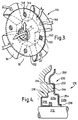
- FIGURE 6 is a schematic side elevation view of part of a fifth embodiment of the invention.
-
- Referring to Figure 1 there is shown part of a
pump 10 according to the invention comprising arotatable shaft 12, apump body 14 and animpeller 16.Impeller 16 comprises a series of blades for effecting fluid flow along the axial direction indicated by arrow I through to a radial outlet direction indicated by arrow 0. -
Pump 10 comprises aseal 18 comprising anannular stepped clip 20 for engaging part of thepump body 14 adjacent the central aperture forshaft 12.Clip 20 carries anannulus 22 having aseat portion 24 for engaging and co-operating with asecond seat portion 26 which in turn is attached to asleeve 28 which is located to effect abutment betweenseats shaft 12. -
Pump 10 further comprises a dividingshroud 32 which is substantially disk shaped, having a radiallyouter cup portion 34 for gripping part ofpump body 14 and a central aperture throughshaft 12, which aperture is defined by alip 38 which extends axially alongshaft 12 away fromseal 18. Shroud 32 further comprises a series ofapertures 36 in a radial outer position. - Shroud 32 divides the
seal chamber 30 forming part of the pumping chamber withinpump 10, whichseal chamber 30 is defined byseal 18 and part of thepump body 14 as well as the face ofimpeller 16. Shroud 32 acts to divide theseal chamber 30 into a first portion 31aadjacent seal 18 and asecond portion 31b which in this embodiment is betweenshroud 32 andimpeller 16. - In use,
shaft 12 is caused to rotate thereby to effect rotation ofimpeller 16 thereby causing fluid flow along the direction of arrow I intopump 10 and out along the direction of arrow 0. Shaft 12 further effects rotation ofsleeve 28 and annularrotational seat 26. The frictional contact betweenseats impeller 16 and stationary stepped annular disc orshroud 32 typically will rotate at approximately half the impeller speed thereby effecting a radial pressure imbalance between the impeller periphery and the shaft seal. No such pressure imbalance is generated between thestationary pump head 14 andshroud 32. A circulation of fluid consisting of a substantially radial inward flow between thestationary pump head 14 andshroud 32 and a radially outwardly spiralling fluid movement betweenshroud 32 and the rotatingimpeller 16 is thus promoted by the impeller thereby enhancing the cooling of theshaft seal 18. - Hence, in accordance with the present invention,
impeller 16 increases fluid flows pastseal 18 along a path throughapertures 36 inshroud 32 down toshaft 12 via the portion 31a ofchamber 30 betweenshroud 32 andseal 18 thereby to effect some cooling ofseal 18. The fluid is further recirculated back into the second portion of the seal chamber betweenshroud 32 andimpeller 16 via the annulus betweenlip 38 onshroud 32 andshaft 12. The fluid is then drawn up towards outlet arrow 0 betweenshroud 32 andimpeller 16 and or drawn through the axial bores orbalance holes 17 inimpeller 16. Accordingly,shroud 32 acts to dividechamber 30 and disrupts the otherwise isolated movement of fluid withinchamber 30, and effects recirculation of fluid aboutseal 18 thereby to provide better cooling of the seal. - Moreover, in impeller pumps where the fluid pressure at the pump inlet is close to the vapour pressure of the pumped medium, it is preferable that the pressure in the seal chamber should be maintained at a level sufficiently remote from the vapour pressure to prevent the pumped medium from boiling and, in the case of coolant pumps in the I.C. engine field, to prevent the well-known phenomenon of filming of the shaft seal surfaces from occurring which leads to coolant leakage.
- In prior art pump arrangements, the pressure of the pumped medium in the
seal chamber 30 can be close to the low pump inlet pressure and if the inlet pressure is close to the vapour pressure of the pumped medium then the additional heat generated by theshaft seal 18 may cause the pumped medium to boil at the seal and/or advance the rate of filming at the shaft seal mating surfaces as just described. - In the arrangement of the present invention, the fluid pressure in portion 31a of
seal chamber 30 is raised to be closer to the higher outlet pressure and henceshroud 32 helps to mitigate the problems in the prior art arrangement by reducing the possibility of boiling and/or filming at theseal 18. This effect is enhanced by ensuring a small running clearance between the internal diameter oflip 38 andshaft 12, and by arranging a series of apertures orslots 36 in theshroud 32 near to the outlet of the pump. Accordingly, the seal chamber pressure self adjusts to a value appreciably closer to the pressure at the impeller periphery than to the pump inlet pressure thereby reducing the possibility of the shaft seal to film over and leak. - In another embodiment of the invention, a pump 110 is provided as shown in part in Figures 2 and 3. In this embodiment, components having identical or like functions to those shown in the first embodiment are given the same two digit reference number prefixed with the number 1. Accordingly, pump 110 comprises a
shaft 112,pump body 114 andseal 118.Shroud 132 comprises a inner steppedannulus 142 which extends down torim 138. Theshroud 132 further comprises a series ofapertures 140 for receivingbolts 147. Referring in particular to Figure 3, it can be seen that thepump body 114 in this embodiment comprises fluid communication passageways which lead intoseal chamber 130 and inparticular portion 131a. In this embodiment, the fluid communication passageways compriseslots 148 between the series of bosses, castellations orcrenallations 144. Thecastellations 144 each comprise a threadedbore 146 for co-operating withbolts 147 thereby to locateshroud 132 in plate. - It should be noted that
shroud 132 shown in Figure 3 differs slightly from that shown in Figure 2 in that stepped innerannular portion 142 is not shown. Beneficially, steppedportion 142 increases the size of the first portion ofcavity 130adjacent seal 118 thereby enabling greater fluid movement in the vicinity of the seal. - Of course, the nature and number of fluid passageways, in this
embodiment slots 148 can be varied. Similarly, the number ofcastellations 144 can be varied such that any number can be provided and not just the four shown in the present embodiment. - Referring to Figure 4, there is shown part of a third embodiment of a
pump 210 according to the invention. Here, like components with the earlier embodiments are given the same two digit reference number prefixed with the number 2. Accordingly, pump 210 comprises ashaft 212,pump body 214,seal 218 andseal chamber 230. A dividingshroud 232 is provided which engages a series ofcastellations 244 at an intermediate radial position. In this embodiment,shroud 232 comprises a radially outercurved portion 250 for guiding fluid down towardscastellations 244.Shroud 232 further comprises an annular steppedportion 252 which grips the radially outer surfaces ofcastellations 244 thereby to fix theshroud 232 in position. Of course, further mechanical attachment devices can be used such as a nut and bolt arrangement as shown in the previous embodiment.Shroud 232 further comprises an inner steppedannulus 244 and finally alip 238. Accordingly, steppedannulus 252 acts to secure theshroud 232 in position whilst steppedannulus 244 acts to increase the area aroundseal 218. - A yet further embodiment of the invention is shown in Figure 5 wherein a
shroud 332 comprises a radiallyouter portion 350 for guiding fluid betweenshroud 332 and pumpbody 314 down towardsapertures 336 in the shroud.Shroud 332 comprises a steppedportion 354 which engages part ofpump body 314 thereby to locate the shroud in position. In this embodiment,shroud 332 further carriesannulus 320 which forms part of the seal 318 (not shown). Accordingly,annulus 320 carries a further annulus 322 and stationary circular seat 324. Beneficially,shroud 332 acts, in particular throughouter portion 350, to increase fluid flow down towardsshaft 312 throughapertures 336 thereby to effect cooling of the seal. - In a further embodiment of the invention shown in Figure 6, a
shroud 432 comprises a stepped radiallyouter portion 460 for engaging crenallations in thepump body 414. The S-shaped central portion ofshroud 432 extends from steppedportion 460 toapertures 436 which can be provided in a circular series around theshroud 432. Accordingly, the central portion ofshroud 436 acts to guide fluid between slots located between the series of bosses orcastellations 444 in the pump and theapertures 436.Shroud 432 further comprises an innerannular clip 420 for engaging part ofpump body 414.Annulus 420 forms part of a seal 418 (not shown), and therefore carries a further annulus and seat for engaging the rotatable part of the seal as shown in earlier embodiments.
Claims (17)
- A fluid pump comprising a body housing a fluid pumping chamber having a rotatable pumping member, a drive shaft which passes through an aperture in the body into the pumping chamber to effect rotation of the pumping member in use, and a seal between the pump body and drive shaft to inhibit fluid moving along the shaft out of the pumping chamber, characterised by a dividing shroud operably located between the seal and the rotatable pumping member to divide the fluid pumping chamber between the seal and the rotatable pumping member.
- A fluid pump according to Claim 1 wherein the dividing shroud is stationary in use.
- A fluid pump according to Claim 1 or 2 wherein a fluid inlet is provided into a first portion of the divided fluid pumping chamber, which first portion is adjacent the seal.
- A fluid pump according to Claim 3 wherein dividing shroud operably creates a pressure gradient across the fluid inlet and first portion of the divided fluid pumping chamber, thereby to effect fluid flow into the first portion.
- A fluid pump according to any preceding claim wherein the dividing shroud comprises an aperture which operably surrounds the drive shaft in use.
- A fluid pump according to Claim 5 wherein the radius of the aperture is slightly greater than the radius of the drive shaft thereby to provide a fluid passageway between the divided portions of the pumping chamber.
- A fluid pump according to Claim 5 or 6 wherein the rim of the aperture is circular.
- A fluid pump according to Claim 5, 6 or 7 wherein the aperture comprises a protruding lip.
- A fluid pump according to Claim 8 wherein the lip extends co-axially along the drive shaft.
- A fluid pump according to Claims 6, 7, 8, or 9 wherein the lip extends away from the seal.
- A fluid pump according to any preceding claim comprising means for attaching the dividing shroud to the pump body.
- A fluid pump according to Claim 11 wherein the shroud comprises an annular resilient clip which engages a lip on the pump body thereby to provide a mechanical/frictional attachment.
- A fluid pump according to any preceding claim comprising a fluid inlet to the first portion having a series of fluid passageways in the pump body around the dividing shroud.
- A fluid pump according to claim 13 wherein the series of fluid passageways comprises a series of castellations, in the pump body.
- A dividing shroud for a seal chamber of a fluid pump.
- A flow enhancer for increasing recirculation of fluid, or pumped medium, past a shaft seal in a pump back into a main fluid flow path between a pump inlet and outlet.
- A fluid pump comprising a body housing a fluid pumping chamber having a rotatable pumping member, a drive shaft which passes through an aperture in the body into the pumping chamber to effect rotation of the pumping member in use, and a seal between the pump body and drive shaft to inhibit fluid moving along the shaft out of the pumping chamber, wherein the fluid pumping chamber comprises a seal chamber defined at least in part by the seal and the rotatable pumping member and wherein the pump further comprises means locatable within the seal chamber for effecting circulation of fluid over the seal and back into a main fluid pumping chamber in use.
Applications Claiming Priority (2)
| Application Number | Priority Date | Filing Date | Title |
|---|---|---|---|
| GB9907372 | 1999-03-30 | ||
| GBGB9907372.8A GB9907372D0 (en) | 1999-03-30 | 1999-03-30 | Improvements in pumps |
Publications (3)
| Publication Number | Publication Date |
|---|---|
| EP1041320A2 true EP1041320A2 (en) | 2000-10-04 |
| EP1041320A3 EP1041320A3 (en) | 2002-08-21 |
| EP1041320B1 EP1041320B1 (en) | 2006-12-27 |
Family
ID=10850686
Family Applications (1)
| Application Number | Title | Priority Date | Filing Date |
|---|---|---|---|
| EP00302554A Expired - Lifetime EP1041320B1 (en) | 1999-03-30 | 2000-03-28 | Improvements in pumps |
Country Status (14)
| Country | Link |
|---|---|
| US (1) | US6402461B1 (en) |
| EP (1) | EP1041320B1 (en) |
| JP (1) | JP2000291598A (en) |
| KR (1) | KR20000062989A (en) |
| CN (1) | CN1269471A (en) |
| AT (1) | ATE349639T1 (en) |
| AU (1) | AU2246100A (en) |
| BR (1) | BR0001466A (en) |
| CA (1) | CA2303569A1 (en) |
| DE (1) | DE60032534T2 (en) |
| GB (2) | GB9907372D0 (en) |
| ID (1) | ID25805A (en) |
| NO (1) | NO20001642L (en) |
| ZA (1) | ZA200001462B (en) |
Cited By (3)
| Publication number | Priority date | Publication date | Assignee | Title |
|---|---|---|---|---|
| GB2386931A (en) * | 2002-03-18 | 2003-10-01 | Aes Eng Ltd | A flow induced mechanical seal for a rotating shaft |
| EP2458225A1 (en) * | 2010-11-24 | 2012-05-30 | Frideco AG | Covering board for a screw centrifuge wheel pump and screw centrifuge wheel pump comprising such a covering board |
| WO2018069691A1 (en) * | 2016-10-10 | 2018-04-19 | Aspen Pumps Limited | Centrifugal pump flow modifier |
Families Citing this family (16)
| Publication number | Priority date | Publication date | Assignee | Title |
|---|---|---|---|---|
| US8465970B2 (en) | 2004-10-07 | 2013-06-18 | Transmedics, Inc. | Systems and methods for ex-vivo organ care |
| US8304181B2 (en) | 2004-10-07 | 2012-11-06 | Transmedics, Inc. | Method for ex-vivo organ care and for using lactate as an indication of donor organ status |
| US9078428B2 (en) | 2005-06-28 | 2015-07-14 | Transmedics, Inc. | Systems, methods, compositions and solutions for perfusing an organ |
| US8506238B2 (en) * | 2006-03-16 | 2013-08-13 | Ford Global Technologies, Llc | Water pump with housing/impeller to enhance seal performance |
| US9457179B2 (en) | 2007-03-20 | 2016-10-04 | Transmedics, Inc. | Systems for monitoring and applying electrical currents in an organ perfusion system |
| KR101430686B1 (en) | 2007-04-05 | 2014-08-14 | 위어 미네랄즈 오스트레일리아 리미티드 | Air Diffuser System for Industrial Pumps |
| US10750738B2 (en) | 2008-01-31 | 2020-08-25 | Transmedics, Inc. | Systems and methods for ex vivo lung care |
| AU2012242578B2 (en) | 2011-04-14 | 2016-07-21 | Transmedics, Inc. | Organ care solution for ex-vivo machine perfusion of donor lungs |
| CN104005982B (en) * | 2013-02-27 | 2016-12-07 | 株式会社久保田 | Pump |
| ITCO20130069A1 (en) | 2013-12-18 | 2015-06-19 | Nuovo Pignone Srl | MULTI-STAGE CENTRIFUGAL COMPRESSOR |
| AU2015271799B2 (en) | 2014-06-02 | 2019-07-11 | Transmedics, Inc. | Ex vivo organ care system |
| JP6010588B2 (en) * | 2014-07-29 | 2016-10-19 | 本田技研工業株式会社 | Centrifugal pump |
| EP3229588A4 (en) | 2014-12-12 | 2019-03-13 | Freed, Darren | Apparatus and method for organ perfusion |
| CA2997267A1 (en) | 2015-09-09 | 2017-03-16 | Transmedics, Inc. | Aortic cannula for ex vivo organ care system |
| CN208169144U (en) * | 2018-02-05 | 2018-11-30 | 上海荣威塑胶工业有限公司 | Pump with waterproof construction |
| CN111720331B (en) * | 2020-05-22 | 2022-08-09 | 洛阳瑞华新能源技术发展有限公司 | Single-stage centrifugal pump with liquid collecting and draining flow channel and flow dividing partition plate having at least 2 liquid draining ports |
Family Cites Families (17)
| Publication number | Priority date | Publication date | Assignee | Title |
|---|---|---|---|---|
| US2777395A (en) * | 1952-03-12 | 1957-01-15 | Union Steam Pump Company | Pump and packing thereof |
| US2769390A (en) * | 1954-06-02 | 1956-11-06 | Brummer Seal Co | Water cooled annular seal |
| US3340813A (en) * | 1965-06-11 | 1967-09-12 | Itt | Centrifugal pumps |
| DE1703090B2 (en) * | 1968-03-26 | 1972-06-15 | Siemens AG, 1000 Berlin u. 8000 München | SELF-PRIMING AXIAL CENTRIFUGAL PUMP |
| GB1258101A (en) | 1969-03-24 | 1971-12-22 | ||
| US3632220A (en) * | 1970-08-27 | 1972-01-04 | Chrysler Corp | Coolant pump |
| US4773823A (en) * | 1984-11-13 | 1988-09-27 | Tolo, Inc. | Centrifugal pump having improvements in seal life |
| JPS61181621A (en) * | 1985-02-06 | 1986-08-14 | Matsushita Refrig Co | Apparatus for adjusting temperature of mold |
| EP0386315A1 (en) * | 1989-03-07 | 1990-09-12 | Feodor Burgmann Dichtungswerke GmbH & Co. | Sealing device and pump provided therewith |
| DE3914652A1 (en) * | 1989-05-03 | 1990-11-08 | Sihi Gmbh & Co Kg | CENTRIFUGAL PUMP |
| CA2015777C (en) * | 1990-04-30 | 1993-10-12 | Lynn P. Tessier | Centrifugal pump |
| GB9018851D0 (en) * | 1990-08-29 | 1990-10-10 | Concentric Pumps Ltd | Coolant pump |
| US5195867A (en) | 1992-03-05 | 1993-03-23 | Barrett, Haentjens & Co. | Slurry pump shaft seal flushing |
| US5409350A (en) * | 1993-10-29 | 1995-04-25 | Caterpillar Inc. | Water pump bearing and seal cartridge |
| US5591001A (en) * | 1994-09-06 | 1997-01-07 | Cornell Pump Manufacturing Corporation | Aeration system |
| US5827041A (en) * | 1996-03-25 | 1998-10-27 | Charhut; Frank J. | Pump and seal arrangement to prevent leakage due to fluid boiling and cavitation |
| US5718436A (en) * | 1996-07-30 | 1998-02-17 | Dunford; Joseph R. | Flow controller for mechanical seal protection |
-
1999
- 1999-03-30 GB GBGB9907372.8A patent/GB9907372D0/en not_active Ceased
-
2000
- 2000-03-21 AU AU22461/00A patent/AU2246100A/en not_active Abandoned
- 2000-03-23 KR KR1020000014698A patent/KR20000062989A/en active IP Right Grant
- 2000-03-28 DE DE60032534T patent/DE60032534T2/en not_active Expired - Lifetime
- 2000-03-28 AT AT00302554T patent/ATE349639T1/en not_active IP Right Cessation
- 2000-03-28 EP EP00302554A patent/EP1041320B1/en not_active Expired - Lifetime
- 2000-03-28 GB GB0007340A patent/GB2348927B/en not_active Expired - Fee Related
- 2000-03-28 US US09/536,773 patent/US6402461B1/en not_active Expired - Lifetime
- 2000-03-29 JP JP2000091749A patent/JP2000291598A/en active Pending
- 2000-03-29 NO NO20001642A patent/NO20001642L/en not_active Application Discontinuation
- 2000-03-30 CN CN00104829A patent/CN1269471A/en active Pending
- 2000-03-30 BR BR0001466-4A patent/BR0001466A/en active Search and Examination
- 2000-03-30 CA CA002303569A patent/CA2303569A1/en not_active Abandoned
- 2000-03-30 ID IDP20000252D patent/ID25805A/en unknown
- 2000-05-25 ZA ZA200001462A patent/ZA200001462B/en unknown
Non-Patent Citations (1)
| Title |
|---|
| None |
Cited By (16)
| Publication number | Priority date | Publication date | Assignee | Title |
|---|---|---|---|---|
| GB2386931A (en) * | 2002-03-18 | 2003-10-01 | Aes Eng Ltd | A flow induced mechanical seal for a rotating shaft |
| EP2458225A1 (en) * | 2010-11-24 | 2012-05-30 | Frideco AG | Covering board for a screw centrifuge wheel pump and screw centrifuge wheel pump comprising such a covering board |
| WO2012069619A1 (en) * | 2010-11-24 | 2012-05-31 | Frideco Ag | Self-cleaning cover plate in a pump with radial flow |
| WO2012069618A1 (en) * | 2010-11-24 | 2012-05-31 | Frideco Ag | Self-cleaning screw-type centrifugal wheel pump with recirculation behind the impeller |
| CN103299085A (en) * | 2010-11-24 | 2013-09-11 | 弗里德科股份公司 | Self-cleaning cover plate in a pump with radial flow |
| CN103339386A (en) * | 2010-11-24 | 2013-10-02 | 弗里德科股份公司 | Self-cleaning screw-type centrifugal wheel pump with recirculation behind the impeller |
| RU2559958C2 (en) * | 2010-11-24 | 2015-08-20 | Фридеко Аг | Self-cleaning rotary screw pump with recycling downstream of impeller |
| RU2566865C2 (en) * | 2010-11-24 | 2015-10-27 | Фридеко Аг | Self-cleaning closing board in radial-flow pump |
| CN103339386B (en) * | 2010-11-24 | 2017-03-29 | 弗里德科股份公司 | Self-cleaning screw-type centrifugal wheel pump with recirculation after the impeller |
| EP3179112A1 (en) | 2010-11-24 | 2017-06-14 | Frideco AG | Pump cover plate with through holes that are designed as inertial filters |
| US9709071B2 (en) | 2010-11-24 | 2017-07-18 | Frideco Ag | Self-cleaning screw-type centrifugal wheel pump with recirculation behind the impeller |
| US9879695B2 (en) | 2010-11-24 | 2018-01-30 | Frideco Ag | Self-cleaning cover plate in a pump with radial flow |
| WO2018069691A1 (en) * | 2016-10-10 | 2018-04-19 | Aspen Pumps Limited | Centrifugal pump flow modifier |
| CN109804165A (en) * | 2016-10-10 | 2019-05-24 | 艾斯本泵业有限公司 | Centrifugal pump flow conditioner |
| US10890353B2 (en) * | 2016-10-10 | 2021-01-12 | Aspen Pumps Limited | Centrifugal pump flow modifier |
| CN109804165B (en) * | 2016-10-10 | 2021-03-12 | 艾斯本泵业有限公司 | Flow regulator of centrifugal pump |
Also Published As
| Publication number | Publication date |
|---|---|
| GB2348927A (en) | 2000-10-18 |
| CN1269471A (en) | 2000-10-11 |
| CA2303569A1 (en) | 2000-09-30 |
| GB9907372D0 (en) | 1999-05-26 |
| ZA200001462B (en) | 2000-10-24 |
| ATE349639T1 (en) | 2007-01-15 |
| EP1041320A3 (en) | 2002-08-21 |
| JP2000291598A (en) | 2000-10-17 |
| DE60032534T2 (en) | 2007-07-05 |
| GB0007340D0 (en) | 2000-05-17 |
| ID25805A (en) | 2000-11-02 |
| NO20001642L (en) | 2000-10-02 |
| EP1041320B1 (en) | 2006-12-27 |
| AU2246100A (en) | 2000-10-05 |
| DE60032534D1 (en) | 2007-02-08 |
| GB2348927B (en) | 2003-12-24 |
| US6402461B1 (en) | 2002-06-11 |
| BR0001466A (en) | 2000-10-10 |
| KR20000062989A (en) | 2000-10-25 |
| NO20001642D0 (en) | 2000-03-29 |
Similar Documents
| Publication | Publication Date | Title |
|---|---|---|
| US6402461B1 (en) | Pumps | |
| JP4124525B2 (en) | Centrifugal pump with integral axial field motor | |
| US4560173A (en) | Mechanical seal assembly with coolant circulation structure | |
| EP0746683B1 (en) | Pump with fluid bearing | |
| US6208512B1 (en) | Contactless hermetic pump | |
| US4589822A (en) | Centrifugal blood pump with impeller | |
| US4466619A (en) | Mechanical seal assembly with integral pumping device | |
| US4872689A (en) | Mechanical seal with heat exchanger | |
| US7264443B2 (en) | Centrifugal water pump | |
| JPH07224766A (en) | Cooling device for magnetic coupling of pump | |
| US8506238B2 (en) | Water pump with housing/impeller to enhance seal performance | |
| US6761359B2 (en) | Spacing element for centering components in a mechanical seal and for promoting circulation of a seal fluid therein | |
| US5567132A (en) | Seal for pump having an internal gas pump | |
| US2938661A (en) | Compressor seals | |
| JPS5821129B2 (en) | journal bearing | |
| US4131386A (en) | Sealing system for centrifugal pump | |
| US3637329A (en) | Pump | |
| US20070221463A1 (en) | Hydrodynamic coupling | |
| GB2390398A (en) | Fluid pump with pumping chamber dividing shroud | |
| CN113958608A (en) | Magnetic fluid bearing | |
| JP2000080919A (en) | Pump | |
| TW527476B (en) | Improvements in pumps | |
| GB2213541A (en) | Pump impeller seals | |
| US9562539B2 (en) | Method and apparatus for sealing a rotating machine using floating seals | |
| CN216867312U (en) | Magnetic fluid bearing |
Legal Events
| Date | Code | Title | Description |
|---|---|---|---|
| PUAI | Public reference made under article 153(3) epc to a published international application that has entered the european phase |
Free format text: ORIGINAL CODE: 0009012 |
|
| AK | Designated contracting states |
Kind code of ref document: A2 Designated state(s): AT BE CH CY DE DK ES FI FR GB GR IE IT LI LU MC NL PT SE |
|
| AX | Request for extension of the european patent |
Free format text: AL;LT;LV;MK;RO;SI |
|
| PUAL | Search report despatched |
Free format text: ORIGINAL CODE: 0009013 |
|
| AK | Designated contracting states |
Kind code of ref document: A3 Designated state(s): AT BE CH CY DE DK ES FI FR GB GR IE IT LI LU MC NL PT SE |
|
| AX | Request for extension of the european patent |
Free format text: AL;LT;LV;MK;RO;SI |
|
| 17P | Request for examination filed |
Effective date: 20030219 |
|
| AKX | Designation fees paid |
Designated state(s): AT BE CH CY DE DK ES FI FR GB GR IE IT LI LU MC NL PT SE |
|
| 17Q | First examination report despatched |
Effective date: 20030528 |
|
| GRAP | Despatch of communication of intention to grant a patent |
Free format text: ORIGINAL CODE: EPIDOSNIGR1 |
|
| GRAS | Grant fee paid |
Free format text: ORIGINAL CODE: EPIDOSNIGR3 |
|
| RAP1 | Party data changed (applicant data changed or rights of an application transferred) |
Owner name: CONCENTRIC PLC |
|
| GRAA | (expected) grant |
Free format text: ORIGINAL CODE: 0009210 |
|
| AK | Designated contracting states |
Kind code of ref document: B1 Designated state(s): AT BE CH CY DE DK ES FI FR GR IE IT LI LU MC NL PT SE |
|
| PG25 | Lapsed in a contracting state [announced via postgrant information from national office to epo] |
Ref country code: IT Free format text: LAPSE BECAUSE OF FAILURE TO SUBMIT A TRANSLATION OF THE DESCRIPTION OR TO PAY THE FEE WITHIN THE PRESCRIBED TIME-LIMIT;WARNING: LAPSES OF ITALIAN PATENTS WITH EFFECTIVE DATE BEFORE 2007 MAY HAVE OCCURRED AT ANY TIME BEFORE 2007. THE CORRECT EFFECTIVE DATE MAY BE DIFFERENT FROM THE ONE RECORDED. Effective date: 20061227 Ref country code: DK Free format text: LAPSE BECAUSE OF FAILURE TO SUBMIT A TRANSLATION OF THE DESCRIPTION OR TO PAY THE FEE WITHIN THE PRESCRIBED TIME-LIMIT Effective date: 20061227 Ref country code: NL Free format text: LAPSE BECAUSE OF FAILURE TO SUBMIT A TRANSLATION OF THE DESCRIPTION OR TO PAY THE FEE WITHIN THE PRESCRIBED TIME-LIMIT Effective date: 20061227 Ref country code: CH Free format text: LAPSE BECAUSE OF FAILURE TO SUBMIT A TRANSLATION OF THE DESCRIPTION OR TO PAY THE FEE WITHIN THE PRESCRIBED TIME-LIMIT Effective date: 20061227 Ref country code: FI Free format text: LAPSE BECAUSE OF FAILURE TO SUBMIT A TRANSLATION OF THE DESCRIPTION OR TO PAY THE FEE WITHIN THE PRESCRIBED TIME-LIMIT Effective date: 20061227 Ref country code: LI Free format text: LAPSE BECAUSE OF FAILURE TO SUBMIT A TRANSLATION OF THE DESCRIPTION OR TO PAY THE FEE WITHIN THE PRESCRIBED TIME-LIMIT Effective date: 20061227 Ref country code: BE Free format text: LAPSE BECAUSE OF FAILURE TO SUBMIT A TRANSLATION OF THE DESCRIPTION OR TO PAY THE FEE WITHIN THE PRESCRIBED TIME-LIMIT Effective date: 20061227 Ref country code: AT Free format text: LAPSE BECAUSE OF FAILURE TO SUBMIT A TRANSLATION OF THE DESCRIPTION OR TO PAY THE FEE WITHIN THE PRESCRIBED TIME-LIMIT Effective date: 20061227 |
|
| RBV | Designated contracting states (corrected) |
Designated state(s): AT BE CH CY DE DK ES FI FR GR IE IT LI LU MC NL PT SE |
|
| REG | Reference to a national code |
Ref country code: IE Ref legal event code: FG4D |
|
| REF | Corresponds to: |
Ref document number: 60032534 Country of ref document: DE Date of ref document: 20070208 Kind code of ref document: P |
|
| PG25 | Lapsed in a contracting state [announced via postgrant information from national office to epo] |
Ref country code: SE Free format text: LAPSE BECAUSE OF FAILURE TO SUBMIT A TRANSLATION OF THE DESCRIPTION OR TO PAY THE FEE WITHIN THE PRESCRIBED TIME-LIMIT Effective date: 20070327 |
|
| PG25 | Lapsed in a contracting state [announced via postgrant information from national office to epo] |
Ref country code: ES Free format text: LAPSE BECAUSE OF FAILURE TO SUBMIT A TRANSLATION OF THE DESCRIPTION OR TO PAY THE FEE WITHIN THE PRESCRIBED TIME-LIMIT Effective date: 20070407 |
|
| PG25 | Lapsed in a contracting state [announced via postgrant information from national office to epo] |
Ref country code: PT Free format text: LAPSE BECAUSE OF FAILURE TO SUBMIT A TRANSLATION OF THE DESCRIPTION OR TO PAY THE FEE WITHIN THE PRESCRIBED TIME-LIMIT Effective date: 20070528 |
|
| NLV1 | Nl: lapsed or annulled due to failure to fulfill the requirements of art. 29p and 29m of the patents act | ||
| REG | Reference to a national code |
Ref country code: CH Ref legal event code: PL |
|
| EN | Fr: translation not filed | ||
| PLBE | No opposition filed within time limit |
Free format text: ORIGINAL CODE: 0009261 |
|
| STAA | Information on the status of an ep patent application or granted ep patent |
Free format text: STATUS: NO OPPOSITION FILED WITHIN TIME LIMIT |
|
| 26N | No opposition filed |
Effective date: 20070928 |
|
| PG25 | Lapsed in a contracting state [announced via postgrant information from national office to epo] |
Ref country code: MC Free format text: LAPSE BECAUSE OF NON-PAYMENT OF DUE FEES Effective date: 20070331 Ref country code: IE Free format text: LAPSE BECAUSE OF NON-PAYMENT OF DUE FEES Effective date: 20070328 |
|
| PG25 | Lapsed in a contracting state [announced via postgrant information from national office to epo] |
Ref country code: GR Free format text: LAPSE BECAUSE OF FAILURE TO SUBMIT A TRANSLATION OF THE DESCRIPTION OR TO PAY THE FEE WITHIN THE PRESCRIBED TIME-LIMIT Effective date: 20070328 Ref country code: FR Free format text: LAPSE BECAUSE OF FAILURE TO SUBMIT A TRANSLATION OF THE DESCRIPTION OR TO PAY THE FEE WITHIN THE PRESCRIBED TIME-LIMIT Effective date: 20070817 |
|
| PG25 | Lapsed in a contracting state [announced via postgrant information from national office to epo] |
Ref country code: FR Free format text: LAPSE BECAUSE OF FAILURE TO SUBMIT A TRANSLATION OF THE DESCRIPTION OR TO PAY THE FEE WITHIN THE PRESCRIBED TIME-LIMIT Effective date: 20061227 |
|
| PG25 | Lapsed in a contracting state [announced via postgrant information from national office to epo] |
Ref country code: LU Free format text: LAPSE BECAUSE OF NON-PAYMENT OF DUE FEES Effective date: 20070328 Ref country code: CY Free format text: LAPSE BECAUSE OF FAILURE TO SUBMIT A TRANSLATION OF THE DESCRIPTION OR TO PAY THE FEE WITHIN THE PRESCRIBED TIME-LIMIT Effective date: 20061227 |
|
| PGFP | Annual fee paid to national office [announced via postgrant information from national office to epo] |
Ref country code: DE Payment date: 20160330 Year of fee payment: 17 |
|
| REG | Reference to a national code |
Ref country code: DE Ref legal event code: R119 Ref document number: 60032534 Country of ref document: DE |
|
| PG25 | Lapsed in a contracting state [announced via postgrant information from national office to epo] |
Ref country code: DE Free format text: LAPSE BECAUSE OF NON-PAYMENT OF DUE FEES Effective date: 20171003 |