EP1041281A2 - Variabler Verdrängungskompressor - Google Patents
Variabler Verdrängungskompressor Download PDFInfo
- Publication number
- EP1041281A2 EP1041281A2 EP00106954A EP00106954A EP1041281A2 EP 1041281 A2 EP1041281 A2 EP 1041281A2 EP 00106954 A EP00106954 A EP 00106954A EP 00106954 A EP00106954 A EP 00106954A EP 1041281 A2 EP1041281 A2 EP 1041281A2
- Authority
- EP
- European Patent Office
- Prior art keywords
- inclination angle
- swash plate
- engaging surface
- drive shaft
- guide hole
- Prior art date
- Legal status (The legal status is an assumption and is not a legal conclusion. Google has not performed a legal analysis and makes no representation as to the accuracy of the status listed.)
- Granted
Links
- 230000007246 mechanism Effects 0.000 claims abstract description 49
- 238000006073 displacement reaction Methods 0.000 claims abstract description 47
- 230000008878 coupling Effects 0.000 claims description 36
- 238000010168 coupling process Methods 0.000 claims description 36
- 238000005859 coupling reaction Methods 0.000 claims description 36
- 230000033001 locomotion Effects 0.000 claims description 17
- 239000003507 refrigerant Substances 0.000 description 10
- 238000004378 air conditioning Methods 0.000 description 9
- 230000006835 compression Effects 0.000 description 5
- 238000007906 compression Methods 0.000 description 5
- 230000007423 decrease Effects 0.000 description 4
- 238000005057 refrigeration Methods 0.000 description 4
- 230000001276 controlling effect Effects 0.000 description 3
- 230000005540 biological transmission Effects 0.000 description 2
- 230000005284 excitation Effects 0.000 description 2
- 230000002452 interceptive effect Effects 0.000 description 2
- 230000004048 modification Effects 0.000 description 2
- 238000012986 modification Methods 0.000 description 2
- 230000000717 retained effect Effects 0.000 description 2
- 230000009471 action Effects 0.000 description 1
- 230000004913 activation Effects 0.000 description 1
- 238000013459 approach Methods 0.000 description 1
- 238000001816 cooling Methods 0.000 description 1
- 230000000694 effects Effects 0.000 description 1
- 230000008030 elimination Effects 0.000 description 1
- 238000003379 elimination reaction Methods 0.000 description 1
- 238000001704 evaporation Methods 0.000 description 1
- 230000008020 evaporation Effects 0.000 description 1
- 238000002474 experimental method Methods 0.000 description 1
- 238000003475 lamination Methods 0.000 description 1
- 230000009467 reduction Effects 0.000 description 1
- 230000001105 regulatory effect Effects 0.000 description 1
- 238000007789 sealing Methods 0.000 description 1
- 239000010802 sludge Substances 0.000 description 1
Images





Classifications
-
- F—MECHANICAL ENGINEERING; LIGHTING; HEATING; WEAPONS; BLASTING
- F04—POSITIVE - DISPLACEMENT MACHINES FOR LIQUIDS; PUMPS FOR LIQUIDS OR ELASTIC FLUIDS
- F04B—POSITIVE-DISPLACEMENT MACHINES FOR LIQUIDS; PUMPS
- F04B49/00—Control, e.g. of pump delivery, or pump pressure of, or safety measures for, machines, pumps, or pumping installations, not otherwise provided for, or of interest apart from, groups F04B1/00 - F04B47/00
- F04B49/12—Control, e.g. of pump delivery, or pump pressure of, or safety measures for, machines, pumps, or pumping installations, not otherwise provided for, or of interest apart from, groups F04B1/00 - F04B47/00 by varying the length of stroke of the working members
- F04B49/123—Control, e.g. of pump delivery, or pump pressure of, or safety measures for, machines, pumps, or pumping installations, not otherwise provided for, or of interest apart from, groups F04B1/00 - F04B47/00 by varying the length of stroke of the working members by changing the eccentricity of one element relative to another element
- F04B49/125—Control, e.g. of pump delivery, or pump pressure of, or safety measures for, machines, pumps, or pumping installations, not otherwise provided for, or of interest apart from, groups F04B1/00 - F04B47/00 by varying the length of stroke of the working members by changing the eccentricity of one element relative to another element by changing the eccentricity of the actuation means, e.g. cams or cranks, relative to the driving means, e.g. driving shafts
-
- F—MECHANICAL ENGINEERING; LIGHTING; HEATING; WEAPONS; BLASTING
- F04—POSITIVE - DISPLACEMENT MACHINES FOR LIQUIDS; PUMPS FOR LIQUIDS OR ELASTIC FLUIDS
- F04B—POSITIVE-DISPLACEMENT MACHINES FOR LIQUIDS; PUMPS
- F04B27/00—Multi-cylinder pumps specially adapted for elastic fluids and characterised by number or arrangement of cylinders
- F04B27/08—Multi-cylinder pumps specially adapted for elastic fluids and characterised by number or arrangement of cylinders having cylinders coaxial with, or parallel or inclined to, main shaft axis
- F04B27/10—Multi-cylinder pumps specially adapted for elastic fluids and characterised by number or arrangement of cylinders having cylinders coaxial with, or parallel or inclined to, main shaft axis having stationary cylinders
- F04B27/1036—Component parts, details, e.g. sealings, lubrication
- F04B27/1054—Actuating elements
- F04B27/1072—Pivot mechanisms
-
- F—MECHANICAL ENGINEERING; LIGHTING; HEATING; WEAPONS; BLASTING
- F04—POSITIVE - DISPLACEMENT MACHINES FOR LIQUIDS; PUMPS FOR LIQUIDS OR ELASTIC FLUIDS
- F04B—POSITIVE-DISPLACEMENT MACHINES FOR LIQUIDS; PUMPS
- F04B1/00—Multi-cylinder machines or pumps characterised by number or arrangement of cylinders
- F04B1/12—Multi-cylinder machines or pumps characterised by number or arrangement of cylinders having cylinder axes coaxial with, or parallel or inclined to, main shaft axis
- F04B1/122—Details or component parts, e.g. valves, sealings or lubrication means
- F04B1/124—Pistons
-
- F—MECHANICAL ENGINEERING; LIGHTING; HEATING; WEAPONS; BLASTING
- F04—POSITIVE - DISPLACEMENT MACHINES FOR LIQUIDS; PUMPS FOR LIQUIDS OR ELASTIC FLUIDS
- F04B—POSITIVE-DISPLACEMENT MACHINES FOR LIQUIDS; PUMPS
- F04B1/00—Multi-cylinder machines or pumps characterised by number or arrangement of cylinders
- F04B1/12—Multi-cylinder machines or pumps characterised by number or arrangement of cylinders having cylinder axes coaxial with, or parallel or inclined to, main shaft axis
- F04B1/128—Driving means
-
- F—MECHANICAL ENGINEERING; LIGHTING; HEATING; WEAPONS; BLASTING
- F04—POSITIVE - DISPLACEMENT MACHINES FOR LIQUIDS; PUMPS FOR LIQUIDS OR ELASTIC FLUIDS
- F04B—POSITIVE-DISPLACEMENT MACHINES FOR LIQUIDS; PUMPS
- F04B1/00—Multi-cylinder machines or pumps characterised by number or arrangement of cylinders
- F04B1/12—Multi-cylinder machines or pumps characterised by number or arrangement of cylinders having cylinder axes coaxial with, or parallel or inclined to, main shaft axis
- F04B1/20—Multi-cylinder machines or pumps characterised by number or arrangement of cylinders having cylinder axes coaxial with, or parallel or inclined to, main shaft axis having rotary cylinder block
- F04B1/2014—Details or component parts
- F04B1/2078—Swash plates
-
- F—MECHANICAL ENGINEERING; LIGHTING; HEATING; WEAPONS; BLASTING
- F05—INDEXING SCHEMES RELATING TO ENGINES OR PUMPS IN VARIOUS SUBCLASSES OF CLASSES F01-F04
- F05B—INDEXING SCHEME RELATING TO WIND, SPRING, WEIGHT, INERTIA OR LIKE MOTORS, TO MACHINES OR ENGINES FOR LIQUIDS COVERED BY SUBCLASSES F03B, F03D AND F03G
- F05B2210/00—Working fluid
- F05B2210/10—Kind or type
- F05B2210/11—Kind or type liquid, i.e. incompressible
Definitions
- the present invention relates to a variable displacement type compressor that has a coupling mechanism for coupling a cam plate, which drives pistons, to a drive shaft and changes the reciprocation stroke of the pistons by altering the inclination angle of the cam plate by controlling the pressure in a crank chamber.
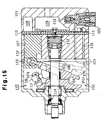
- Figure 15 shows one type of a variable displacement type compressor for use in a vehicle air-conditioning system.
- a crank chamber 102 Accommodated in a housing 101 of the compressor are a crank chamber 102, a suction chamber 108, a discharge chamber 109 and a plurality of cylinder bores 107 (only one shown).
- a piston 110 is retained in each cylinder bore 107.
- a drive shaft 103 and a lug plate 104, which are fixed to each other, are located in the crank chamber 102.
- the housing 101 is provided with a lip seal 114 around the front end of the drive shaft 103.
- the front end of the drive shaft 103 is coupled to the engine (external drive source) of the vehicle directly or indirectly.
- a spring 112 for urging the drive shaft 103 in a forward direction is located at the rear end of the drive shaft 103.
- the spring 112 positions the drive shaft 103 and the lug plate 104 in the crank chamber 102 in the axial direction while absorbing the tolerances of the drive shaft 103 and various components associated with the drive shaft 103.
- a swash plate 105,or cam plate Provided around the drive shaft 103 is a swash plate 105,or cam plate.
- the swash plate 105 which is coupled to the individual pistons 110 via shoes 113, converts the rotational motion of the drive shaft 103 to reciprocal motion of each piston 110.
- This swash plate 105 is coupled to the lug plate (rotary support) 104 via a coupling mechanism 115.
- the coupling mechanism 115 has guide pins 116 protruding from the front face of the swash plate 105 and support arms 117 protruding from the rear face of the lug plate 104. The head of each guide pin 116 is inserted into a cylindrical guide hole 117a formed in the associated support arm 117.
- This coupling mechanism 115 allows the swash plate 105 to rotate with the drive shaft 103 and to tilt as the swash plate 105 moves along the drive shaft 103 (in the axial direction).
- the stroke of the pistons 110, or the discharge displacement, is determined by the inclination angle of the swash plate 105, which is mainly determined by the difference between the pressure of the crank chamber 102 (crank pressure Pc) and the pressure in the cylinder bores 107 via the associated piston 110. This difference is controlled by a displacement control valve 120.
- crank pressure Pc the pressure of the crank chamber 102
- a displacement control valve 120 the swash plate 105 disinclines, or slides on the drive shaft 103 away from the lug plate 104, making the inclination angle of the swash plate 105 smaller.
- a restriction ring 106 is fixed on the drive shaft 103 so that, when the swash plate 105 contacts the restriction ring 106, further disinclination of the swash plate 105 is restricted, thereby defining the minimum inclination angle of the swash plate 105.
- the control mechanism for the crank pressure Pc comprises a restriction-equipped bleed passage 118, which connects the crank chamber 102 to the suction chamber 108, an supply passage 119, which connects the discharge chamber 109 to the crank chamber 102, and the displacement control valve 120 located midway in the supply passage 119. The opening of this displacement control valve 120 can be adjusted by external energization.
- this control valve 120 As the opening of this control valve 120 is adjusted externally, the amount of high-pressure refrigerant gas supplied into the crank chamber 102 from the discharge chamber 109 via the supply passage 119 is adjusted.
- the crank pressure Pc is determined by the relationship between the flow rate of gas supplied to the crank chamber 102 and the flow rate of gas that is released from the crank chamber 102 via the bleed passage 118.
- the capacity of the compressor is minimized to reduce the engine load as much as possible when rapidly accelerating the vehicle.
- the discharge capacity of the compressor is often minimized in advance to prevent the next activation of the compressor from applying an excess load to the engine.
- the capacity of the compressor is minimized by supplying high-pressure refrigerant gas into the crank chamber 102 from the discharge chamber 109 with the displacement control valve fully opened by an external signal. To minimize the capacity of the compressor when rapidly accelerating the vehicle, particularly, it is necessary to quickly minimize the discharge capacity. Thus, high-pressure refrigerant gas is often rapidly led into the crank chamber 102.
- the inclination angle of the swash plate 105 is minimized and the swash plate 105 abuts against the restriction ring 106.
- the swash plate 105 urges the drive shaft 103 against the force of the spring 112 via the restriction ring 106.
- the swash plate 105 is coupled to the lug plate 104 by the engagement of each guide pin 116 and the associated guide hole 117a of the coupling mechanism 115. If the swash plate 105 is rapidly disinclined, the swash plate 105 pulls the lug plate 104 and the drive shaft 103 rearward against the force of the spring 112.
- an electromagnetic clutch is located in the power transmitting path between the engine and the drive shaft 103.
- the typical electromagnetic clutch has a drive clutch plate on the engine side and a driven clutch plate (armature), which rotates with the drive shaft 103 and can be shifted axially by the force of a spring.
- the clutch is engaged by electromagnetically engaging the armature and the drive clutch plate. when the electric power is cut off, a predetermined gap should exist between the armature and the drive clutch plate.
- the electromagnetic clutch is deactivated and the displacement control valve 120 is fully opened. As the displacement control valve 120 is fully open, as mentioned above, the drive shaft 103 moves further rearward beyond the design limit.
- the armature together with the drive shaft 103 approaches the drive clutch plate from the original separated position so that the predetermined gap between both clutch plates may not be secured at all. That is, in spite of the attempted power cutoff action, the armature and the drive clutch plate have a slide contact with each other. This slide contact not only disables the power cutoff but also brings about a new problem of producing noise or heat or wearing the clutch plates.
- variable displacement type compressor which prevents the drive shaft from being pulled rearward by the swash plate (cam plate) coupled to the pistons and moving rearward over the design limit in the axial direction even when the difference between the crank pressure and the inner pressure of each cylinder bore via the associated piston is excessively large as a result of the rapid rise in crank pressure in a short period of time due to an internal or external factor.
- a variable displacement type compressor comprising: pistons for performing a compressing operation; a cam plate located in a crank chamber and coupled to the pistons for converting rotation of a drive shaft to a reciprocal motion of the pistons, the stroke of which depends on the inclination angle of said cam plate, which varies according to the pressure in said crank chamber; and a coupling mechanism for coupling the cam plate to the drive shaft, the coupling mechanism including: a rotary support that rotates integrally with the drive shaft; a first engaging surface provided on the rotary support; and a second engaging surface provided on the cam plate, wherein the first engaging surface and the second engaging surface engage and couple the cam plate to the rotary support to permit said inclination of the cam plate with respect to said drive shaft, characterized in that at least one of the first engaging surface and the second engaging surface has a predetermined shape that causes the first engaging surface to separate and disengage from the second engaging surface when the inclination angle of said cam plate is at or near a
- variable displacement type swash plate compressor includes a cylinder block 1, a front housing 2 which is connected to the front end of the cylinder block 1, and a rear housing 4 which is connected through a valve plate 3 to the rear end of the cylinder block 1.
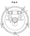
- the cylinder block 1, front housing 2, valve plate 3 and rear housing 4 are securely joined by a plurality of bolts 10 (see Figure 5) to form compressor housing.
- a crank chamber 5 is defined by the cylinder block 1 and the front housing 2.
- a drive shaft 6 is located in the crank chamber 5 and is supported front and rear radial bearings 31 and 32, which are respectively provided in the front housing 2 and the cylinder block 1.
- a first coil spring 7, which urges the drive shaft 6 forward and a rear thrust bearing 8.
- a lug plate 11 is fixed to the drive shaft 6.
- a front thrust bearing 9 is located between the lug plate 11 and the inner wall of the front housing 2.
- the drive shaft 6 and lug plate 11 are axially positioned by the rear thrust bearing 8, which is urged in a forward direction by the first coil spring 7, and the front thrust bearing 9.
- the front end of the drive shaft 6 protrudes from the front portion of the front housing 2.
- a lip seal 33 is located between the outer surface of the drive shaft 6 and the inner surface of the front portion of the front housing 2.
- the lip seal 33 has a lip ring 34 which firmly contacts the outer surface of the drive shaft 6, thereby sealing the front of the drive shaft 6 to hermetically seal the crank chamber 5.
- the front end of the drive shaft 6 is coupled to a vehicular engine E as an external drive source through an electromagnetic clutch 40.
- the electromagnetic clutch 40 has a pulley 42, a ring-like solenoid coil 43, a hub 44 which is made of an elastic member, and an armature 45.
- the pulley 42 is supported on the front cylindrical portion of the front housing 2 by a bearing 41.
- the hub 44 is secured to the front end of the drive shaft 6.
- Figure 1 shows the armature 45 engaged with the end face of the pulley 42 against the forward elastic force of the hub 44.
- the end face of the pulley 42 and the armature 45 serve as a pair of clutch plates, which can engage and separate from each other.
- the driving power of the engine E is transmitted to the drive shaft 6 through a power transmission belt 46, the pulley 42, the armature 45 and the hub 44.
- the armature 45 moves away from the pulley 42 by the elastic force of the hub 44, thus discontinuing power transmission.
- the engine power is therefore selectively transmitted to the drive shaft 6 by controlling the excitation of the coil 43 of the electromagnetic clutch 40.
- a cam plate which is a swash plate 12 in this embodiment, is accommodated in the crank chamber 5.
- the drive shaft 6 passes through a hole formed in the center of the swash plate 12.
- the swash plate 12 is coupled to the lug plate 11 and the drive shaft 6 through a hinge mechanism 13.
- the hinge mechanism 13 includes two support arms 14 (holding members), which protrude from the rear face of the lug plate 11, and two guide pins 15 (inserting members), which protrude from the front face of the swash plate 12 (see Figures 1 and 5).
- the hinge mechanism 13 and the lug plate 11 form a coupling mechanism, which will be discussed later in detail.
- the linkage of the support arms 14 and the guide pins 15 and the contact of the swash plate 12 with the drive shaft 6 causes the swash plate 12 to rotate with the lug plate 11 and the drive shaft 6 and allows the swash plate 12 to tilt with respect to the axis L1 of drive shaft 6 as the swash plate 12 slides along the drive shaft 6.
- the swash plate 12 has a counter weight 12a located opposite to the hinge mechanism 13.
- a second coil spring 16 for reducing the inclination angle of the swash plate 12 is provided on the drive shaft 6 between the lug plate 11 and the swash plate 12.
- the coil spring 16 urges the swash plate 12 toward the cylinder block 1 (i.e., in a direction reducing the inclination angle of the swash plate 12).
- a third coil spring 17, or return spring is provided on the drive shaft 6 behind the swash plate 12 , or between the swash plate 12 and the front end face 1c of the cylinder block 1 (the face of the cylinder block 1 on the crank chamber side).
- the third coil spring 17 is simply wound around the drive shaft 6 and does not apply force to the swash plate 12 or any other member and is movable along the drive shaft 6 while keeping its natural length.
- the third coil spring 17 is compressed between the swash plate 12 and the front end face 1c of the cylinder block 1, and urges the swash plate 12 away from the cylinder block 1 (i.e., in the direction increasing the inclination angle of the swash plate 12) in accordance with the degree of compression of the coil with the front end face 1c serving as a support seat.
- the natural length of the third coil spring 17 and the axial position of the front end face 1c are set so that the third coil spring (return spring) 17 is not compressed all the way even when the swash plate 12 reaches the designed minimum inclination angle ⁇ min (ranging between 1 to 5°) when the compressor is in operation.
- each cylinder bore 1a (only one shown) are formed in the cylinder block 1 to surround the drive shaft 6.
- the rear end of each cylinder bore 1a is closed by the valve plate 3.
- a single-headed piston 18 is retained in each cylinder bore 1a.
- Defined in each cylinder bore 1a is a compression chamber, the volume of which changes in accordance with the reciprocation of the associated piston 18.
- the front end of each piston 18 is connected to the periphery of the swash plate 12 via a pair of shoes 19, so that the pistons 18 can be driven by the swash plate 12.
- the rotational motion of the swash plate 12 is converted to linear reciprocating motion of the pistons 18, and the stroke corresponds to the inclination angle ⁇ of the swash plate 12.
- the use of the above-described hinge mechanism 13 keeps the top dead centers of the pistons 18 approximately constant. This allows the top clearance C1 (see Figure 2) to be kept at a desired value.
- the top clearance C1 is not set to zero but is a very small value.
- the valve plate 3 is a lamination of a suction-valve forming plate, a port forming plate, a discharge-valve forming plate and a retainer forming plate.
- a suction port 23, a suction valve 24 for opening and closing the suction port 23, a discharge port 25, and a discharge valve 26 for opening and closing the discharge port 25 are formed in the valve plate 3 in association with each cylinder bore 1a.
- the suction chamber 21 is connected to the individual cylinder bores 1a through the suction port 23, and the discharge chamber 22 is connected to the individual cylinder bores 1a through the discharge port 25.
- the inclination angle ⁇ of the swash plate 12 is determined based on the balance of various moments, such as a rotational moment caused by centrifugal force during rotation of the swash plate 12, a moment caused by the urging force of the spring 16 (and the return spring 17), which decreases the inclination angle of the swash plate 12, a moment caused by the reciprocal force of inertia of the pistons 18, and a moment caused by the gas pressure.
- the gas-pressure moment is generated based on the relationship between the cylinder-bore inner pressure and the inner pressure of the crank chamber 5 (crank pressure Pc), which is known as the piston back pressure, and acts both in the direction of reducing the inclination angle of the swash plate 12 and in the direction of increasing it depending on the crank pressure Pc.
- crank pressure Pc crank pressure
- the compressor in Figure 1 is designed to be able to vary the inclination angle ⁇ of the swash plate 12 to any angle between the minimum inclination angle ⁇ min and a maximum inclination angle ⁇ max ( ⁇ min ⁇ ⁇ ⁇ ⁇ max) by properly changing the gas-pressure moment, which is done by adjusting the crank pressure Pc with a displacement control valve 50 (discussed later).
- the inclination angle ⁇ of the swash plate 12 is the angle defined by the swash plate 12 and an imaginary plane perpendicular to the axis L1 of the drive shaft 6.
- the maximum inclination angle ⁇ max of the swash plate 12 is in effect when the counter weight 12a of the swash plate 12 abuts against a restriction portion 11a of the lug plate 11 (see Figure 1).
- the minimum inclination angle ⁇ min of the swash plate 12 is determined mainly by the urging force of the second spring 16, the urging force of the return spring 17 and the gas-pressure moment, which is nearly maximized in the direction of reducing the inclination angle of the swash plate 12.
- the minimum inclination angle ⁇ min is not determined by a mechanical stop.
- the inclination angle ⁇ min is an angle around zero. Therefore, while it is not possible to fit a constant minimum inclination angle ⁇ min, the discharge capacity of the compressor is reduced sufficiently at the minimum inclination angle just as if the minimum inclination angle were determined by a mechanical stop.
- the crank pressure Pc which greatly affects the inclination angle of the swash plate 12, is controlled by a bleed passage 27, an supply passage 28 and the displacement control valve 50, all of which are in the housing of the compressor, as shown in Figures 1 and 2.
- the bleed passage 27 connects the suction chamber 21 to the crank chamber 5, and the supply passage 28 connects the discharge chamber 22 to the crank chamber 5.
- the displacement control valve 50 is in the supply passage 28. Adjusting the position of the control valve 50 regulates the flow rate of high-pressure gas supplied to the crank chamber 5 via the supply passage 28 with respect to the flow rate of gas released from the crank chamber 5 via the bleed passage 27.
- the crank pressure Pc is determined accordingly. As the crank pressure Pc changes, the difference between the crank pressure Pc and the inner pressure of the cylinder bore 1a is changed. This alters the inclination angle of the swash plate 12, which adjust the piston stroke, or the discharge displacement.
- the displacement control valve 50 has a valve chamber 51, a valve hole 52, a spherical valve body 53, and a spring 53a, which urges the valve body 53 in a direction to close the valve hole 52.
- the valve chamber 51 and the valve hole 52 form part of the supply passage 28.
- the control valve 50 further includes a solenoid 54, which includes a fixed core 55, a movable core 56, a coil 57, which extends about both cores, and a spring 58, which opens the valve hole 52.
- the movable core 56 and the valve body 53 are connected by a rod 59.
- the spring 58 urges the valve body 53 via the movable core 56 and the rod 59 in a direction to open the valve hole 52.
- the suction chamber 21 and the discharge chamber 22 of the compressor shown in, for example, Figure 1 are connected through an external refrigeration circuit 60.
- the external refrigeration circuit 60 and the compressor form a cooling circuit of a vehicle air-conditioning system.
- the external refrigeration circuit 60 includes a condenser 61, a temperature-sensitive expansion valve 62 and an evaporator 63.
- the angle of the expansion valve 62 is feedback controlled based on the temperature detected by a temperature sensing cylinder 64 provided at the outlet side of the evaporator 63 and the evaporation pressure (specifically, the pressure at the outlet of the evaporator).
- the expansion valve 62 allows an amount of refrigerant that matches the thermal load to be supplied to the evaporator 63, thereby regulating the flow rate of the refrigerant gas in the external refrigeration circuit 60.
- the air-conditioning system has a computer C, which performs general control of the air-conditioning system.
- a computer C Connected to the input side of the computer C are, for example, a temperature sensor 65 for detecting the temperature inside the passenger compartment, a temperature setting unit 66 for allowing a passenger to set the temperature inside the passenger compartment, and an engine speed sensor 67 for detecting the rotational speed of the engine E of the vehicle.
- the output side of the computer C is connected via a drive circuit 68 to the coil 57 of the control valve 50.
- the computer C computes the level of the current to be supplied to the coil 57 based on external information, such as the temperature of the passenger compartment from the temperature sensor 65, the temperature set by the temperature setting unit 66 and the engine speed detected by the engine speed sensor 67 and supplies the current to the coil 57 via the drive circuit 68 in accordance with the result of the computation.
- the coupling mechanism includes the lug plate (rotary support) 11 and the hinge mechanism 13.
- the hinge mechanism 13 includes the two support arms 14 and the two guide pins 15.
- the right and left guide pins 15 are associated with the respective two support arms 14.
- a set of one support arm 14 and one guide pin 15 forms the smallest essential mechanism.
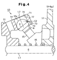
- Figures 3 and 4 show one set of the support arm 14 and the guide pin 15.
- Figure 3 shows the support arm 14 engaged with the associated guide pin 15 when the swash plate 12 is at the maximum inclination angle ⁇ max
- Figure 4 shows the condition when the swash plate 12 is at the minimum inclination angle ⁇ min.
- each guide pin 15 obliquely extends upward and forward from the front face of the swash plate 12.
- An approximately spherical head portion 15a is formed at the distal end of each guide pin 15.
- An annular socket is provided at the distal end of each support arm 14.
- a cylindrical guide hole 70 is formed inside each socket.
- the head portion 15a of each guide pin 15 is fitted into the corresponding guide hole 70 and is guided by the wall of the hole 70.
- the guide hole 70 may be a recess instead of a hole.
- the axis L2 of the guide hole 70 approximately coincides with the axis of the guide pin 15 in Figure 3.
- the thickness of the annular wall of the support arm 14 that defines the cylindrical guide hole 70 varies in the direction of the axial line L2.
- the portion of the annular wall on the rear side of the axis L2 is divided into an upper portion 71, a middle portion 72 and a lower portion 73.
- the upper portion 71 and the middle portion 72 of the support arm 14 are formed in such a way that the inside diameter of the guide hole 70 is nearly equal to the maximum diameter D of the head portion 15a of the guide pin 15. That is, when the head portion 15a of the guide pin 15 is in the upper area or middle area of the guide hole 70 (i.e., when the swash plate 12 is inclined at the maximum inclination angle or at an intermediate angle between the maximum inclination angle and the minimum inclination angle), nearly the entire circumference of the head portion 15a contacts the inner surface of the socket.
- the guide pin 15 is securely held while sliding motion and rocking motion are permitted in accordance with changes in the inclination angle of the swash plate 12.
- the lower portion 73 of the support arm 14 is cut away and is thus thinner than the upper portion 71 and the middle portion 72.
- An imaginary line M indicates the location of the wall of the guide hole 70, and an angled surface 74 is formed on the lower portion 73 at a position rearward of the imaginary line M. Without the angled surface 74, when the head portion 15a of the guide pin 15 is positioned in the lower portion 73 (i.e., when the inclination angle of the swash plate 12 is minimum as shown in Figure 4), the head portion 15a would contact the wall of the guide hole 70 at a location indicated by the imaginary line M.
- the clearance is set so that the minimum clearance C2 (as measured along a line parallel to the axis L1) is equal to or greater than the top clearance C1 of the piston 18. That is, since C1 ⁇ C2, when the guide pin 15 and the swash plate 12 move toward the cylinder block 1, the guide pin 15 and the lower portion 73 of the associated support arm 14 are prevented from interfering with each other until the end face of the piston 18 contacts the valve plate 3.
- the cooperation of the support arms 14 and guide pins 15 of the coupling mechanism allows the swash plate 12 to rotate integrally with the lug plate 11 and the drive shaft 6 and to tilt with respect to the drive shaft 6 while sliding on and along the drive shaft 6.
- the rear portion of the guide pin 15 does not interfere with the inner surface of the corresponding socket. Therefore, the guide pin 15 and the swash plate 12 are permitted to move further toward the cylinder block 1 in the direction of the axis L1 of the drive shaft 6. When such movement takes place, the guide pin 15 does not pull the support arm 14.
- the guide hole 70 allows the guide pin 15 to slide and move upward along the axis L2 of the guide hole 70.
- the temperature of the vehicle passenger compartment may be set higher at the temperature setting unit 66 while the compressor is running at the maximum discharge displacement (at the maximum inclination angle of the swash plate). Further, the engine speed that is detected by the engine speed sensor 67 may increase abruptly due to sudden depression of the accelerator. In these cases, the computer C deexcites the solenoid 54 of the displacement control valve 50 to minimize the discharge displacement of the compressor. When the air-conditioning system is switched off or the engine E is stopped, the computer C likewise deexcites the solenoid 54 of the displacement control valve 50.
- the deexcitation of the solenoid 54 opens the valve hole 52 of the control valve 50 to rapidly increase the opening size of the supply passage 28 so that the high-pressure refrigerant gas in the discharge chamber 22 swiftly flows into the crank chamber 5.
- the flow rate of refrigerant gas through the bleed passage 27 is relatively small. Therefore, the crank pressure Pc abruptly increases. As a result, the difference between the crank pressure Pc and the cylinder-bore pressure increases, which minimizes the inclination angle of the swash plate 12.
- the pistons 18 are moved toward the valve plate 3. Accordingly, the swash plate 12 is pulled in a rearward axial direction.
- the cutaway surfaces 74 formed on the sockets of the support arms 14 provide the minimum clearances C2 so that the guide pin 15 and the support arm 14 do not interfere with each other. This permits the pistons 18, the shoes 19, the swash plate 12 and the guide pins 15, which are integrated into one assembly, to independently move axially rearward.
- the force of the return spring 17 affects the positioning of the swash plate 12.
- the force of the return spring 17 and the force of the spring 16 to reduce the inclination angle of the swash plate 12, the inclination angle ⁇ of the swash plate 12 gradually converges to near the minimum inclination angle ⁇ min (or an intermediate angle between the minimum inclination angle ⁇ min and the maximum inclination angle ⁇ max depending on the operational state of the compressor).
- the swash plate 12 When disinclining, the swash plate 12 is disengaged from the walls of guide holes 70 and becomes unstable in the axial direction.
- the swash plate 12 When the swash plate 12 is pushed back forward influenced by the return spring 17 and its inclination angle becomes equal to or greater than the minimum inclination angle ⁇ min, however, the spherical head portion 15a of each guide pin 15 reaches the boundary between the middle portion 72 and the lower portion 73 of the corresponding socket while being guided a long the angled cutaway surface 74. Therefore, the head portion 15a of each guide pin 15 is smoothly be engaged again with the annular middle portion 72.
- this embodiment has the following advantages.
- a variable displacement type swash plate compressor that prevents a drive shaft (6) from moving axially when the difference between a crank chamber pressure and a cylinder bore pressure becomes excessive.
- a hinge mechanism (13) has a support arm (14) extending from a lug plate (11) and a guide pin (15) extends from a swash plate (12). The head portion (15a) of the guide pin (15) fits in a guide hole (70) formed in the support arm (14).
- a cutaway surface (74) is formed in a part (73) of the support arm that defines the guide hole (70). The cutaway surface (74) forms a clearance (C2) in the hinge. The clearance (C2) permits the swash plate (12) to move without pulling the drive shaft (6).
Landscapes
- Engineering & Computer Science (AREA)
- Mechanical Engineering (AREA)
- General Engineering & Computer Science (AREA)
- Compressors, Vaccum Pumps And Other Relevant Systems (AREA)
Abstract
Description
Claims (12)
- A variable displacement type compressor comprising: pistons (18) for performing a compressing operation; a cam plate (12), located in a crank chamber (5) and coupled to the pistons for converting rotation of a drive shaft (6) to a reciprocal motion of the pistons, the stroke of which depends on the inclination angle of said cam plate, which varies according to the pressure in said crank chamber; and a coupling mechanism for coupling the cam plate to the drive shaft, the coupling mechanism including: a rotary support (11) that rotates integrally with the drive shaft; a first engaging surface (14, 70; 86; 88, 88a; 94, 95) provided on the rotary support; and a second engaging surface (15, 15a; 84, 85; 89, 90; 99) provided on the cam plate, wherein the first engaging surface and the second engaging surface engage and couple the cam plate to the rotary support to permit said inclination of the cam plate with respect to said drive shaft, characterized in that at least one of the first engaging surface and the second engaging surface has a predetermined shape (74; 81; 81A; 87; 93) that causes the first engaging surface to separate and disengage from the second engaging surface when the inclination angle of said cam plate is at or near a minimum.
- The variable displacement type compressor according to claim 1, wherein the coupling mechanism allows a top clearance of the pistons (18) to become zero when the inclination angle of the cam plate (12) is minimized.
- The variable displacement type compressor according to claim 1, wherein the coupling mechanism does not transmit the pressure in the crank chamber (5) acting on the pistons (18) to the drive shaft (6) when the inclination angle of the cam plate (12) is minimized.
- The variable displacement type compressor according to claim 1, wherein said first engaging surface is part of a socket (14), which includes a cylindrical guide hole (70), and the second engaging surface is part of a spherical portion (15a) that fits into the guide hole, wherein the predetermined shape is a cutaway portion (74) formed in the socket and intersects the guide hole, the predetermined shape being located at a location where the spherical portion is located when the inclination angle of the cam plate is minimized, and the predetermined shape is opposite to the rotary support (11) with respect to the spherical portion.
- The variable displacement type compressor according to claim 4, wherein the inside diameter of the guide hole (70) at a location apart from the cutaway portion (74) is substantially equal to the maximum diameter of the spherical portion (15a).
- The variable displacement type compressor according to claim 1, wherein the first engaging surface is a socket (14) having a cylindrical guide hole (70), and the second engaging surface is a spherical inserting portion (15a) that fits in the guide hole, and the predetermined shape is a cutaway portion (81) formed on a side of the spherical portion (15a) that faces away from the rotary support.
- The variable displacement type compressor according to claim 1, wherein the first engaging surface is on a socket (14) having a cylindrical guide hole (70), and the second engaging surface is on a spherical portion (15a) that fits in the guide hole, wherein the predetermined shape is a cutaway portion (81A) formed in an entire surface of the spherical portion (15a), wherein the shape of the spherical portion is constant about an axis passing through the center of the spherical portion.
- The variable displacement type compressor according to claim 6 or 7, wherein the inside diameter of the guide hole (70) is substantially equal to the maximum diameter of the spherical portion (15a).
- The variable displacement type compressor according to any one of claims 1 to 7, further comprising a return spring (17) for urging the cam plate in a direction to increase inclination angle of cam plate when said inclination angle of the cam plate (12) is small.
- The variable displacement type compressor according to any one of claims 4 to 7, wherein a clearance (C2) is formed between the spherical portion (15a) and the surface of the guide hole (70) by the predetermined shape (74) when the inclination angle of the cam plate (12) is minimized, and the clearance is equal to or greater than a top clearance (C1) of the pistons (18).
- The variable displacement type compressor according to claim 1, wherein the second engaging surface is located on a holder (84) having a guide hole (85), the first engaging surface is a rod-like structure (86) that fits into the guide hole, and the predetermined shape (87) is formed in an inner surface of the guide hole at a location where the first engaging surface is located when the inclination angle of the cam plate is minimized, and the predetermined shape is located between the rod-like structure and the rotary support (11).
- The variable displacement type compressor according to claim 1, wherein the second engaging surface is a socket (89) having a guide groove (90), the first engaging surface is a spherical portion (88a) that fits in the guide groove, the predetermined shape is an enlargement (93) of the groove and the enlargement is formed at a location where the first engaging surface is located when said inclination angle of said cam plate is a minimized, and the enlargement creates a space between the spherical portion and the rotary support (11).
Applications Claiming Priority (4)
| Application Number | Priority Date | Filing Date | Title |
|---|---|---|---|
| JP9592699 | 1999-04-02 | ||
| JP9592699 | 1999-04-02 | ||
| JP16104799A JP4035922B2 (en) | 1999-04-02 | 1999-06-08 | Variable capacity compressor |
| JP16104799 | 1999-06-08 |
Publications (3)
| Publication Number | Publication Date |
|---|---|
| EP1041281A2 true EP1041281A2 (en) | 2000-10-04 |
| EP1041281A3 EP1041281A3 (en) | 2001-03-14 |
| EP1041281B1 EP1041281B1 (en) | 2005-06-01 |
Family
ID=26437095
Family Applications (1)
| Application Number | Title | Priority Date | Filing Date |
|---|---|---|---|
| EP00106954A Expired - Lifetime EP1041281B1 (en) | 1999-04-02 | 2000-03-31 | Variable displacement type compressor |
Country Status (7)
| Country | Link |
|---|---|
| US (1) | US6283722B1 (en) |
| EP (1) | EP1041281B1 (en) |
| JP (1) | JP4035922B2 (en) |
| KR (1) | KR100370749B1 (en) |
| CN (1) | CN1175183C (en) |
| BR (1) | BR0001113A (en) |
| DE (1) | DE60020440T2 (en) |
Cited By (2)
| Publication number | Priority date | Publication date | Assignee | Title |
|---|---|---|---|---|
| EP3477104A1 (en) * | 2017-10-26 | 2019-05-01 | Valeo Japan Co., Ltd. | Variable displacement compressor, in particular for a refrigerant circuit of a vehicle air condition system |
| EP3477105A1 (en) * | 2017-10-26 | 2019-05-01 | Valeo Japan Co., Ltd. | Variable displacement compressor, in particular for a refrigerant circuit of a vehicle air condition system |
Families Citing this family (15)
| Publication number | Priority date | Publication date | Assignee | Title |
|---|---|---|---|---|
| JP2001304108A (en) * | 2000-04-20 | 2001-10-31 | Toyota Industries Corp | Compressor |
| JP2002005011A (en) * | 2000-06-27 | 2002-01-09 | Toyota Industries Corp | Variable displacement compressor |
| JP2002054662A (en) * | 2000-08-11 | 2002-02-20 | Toyota Industries Corp | Power transmission mechanism |
| KR20020067964A (en) * | 2001-02-19 | 2002-08-24 | 가부시키가이샤 도요다 지도숏키 | Method of manufacturing valve plate for compressor |
| JP2003083244A (en) * | 2001-09-06 | 2003-03-19 | Nippon Soken Inc | Swash plate type variable capacity compressor |
| JP3741022B2 (en) * | 2001-10-15 | 2006-02-01 | 株式会社豊田自動織機 | Air conditioner for vehicles |
| JP2003269329A (en) * | 2002-03-15 | 2003-09-25 | Sanden Corp | Compressor for vehicle |
| JP2006022785A (en) * | 2004-07-09 | 2006-01-26 | Toyota Industries Corp | Variable displacement compressor |
| JP5579144B2 (en) * | 2011-09-22 | 2014-08-27 | サンデン株式会社 | Variable capacity compressor |
| FR2998023B1 (en) * | 2012-11-12 | 2015-09-04 | Skf Ab | PULLEY DEVICE, ROTATING MACHINE EQUIPPED WITH SUCH DEVICE AND METHOD FOR MOUNTING SUCH A DEVICE ON A ROTATING MACHINE |
| JP5999622B2 (en) * | 2012-02-06 | 2016-09-28 | サンデンホールディングス株式会社 | Variable capacity compressor |
| JP6013768B2 (en) * | 2012-04-25 | 2016-10-25 | サンデンホールディングス株式会社 | Variable capacity compressor and manufacturing method thereof |
| JP6063150B2 (en) * | 2012-05-28 | 2017-01-18 | サンデンホールディングス株式会社 | Variable capacity compressor |
| JP6047307B2 (en) * | 2012-05-28 | 2016-12-21 | サンデンホールディングス株式会社 | Variable capacity compressor |
| CN119878486B (en) * | 2024-12-24 | 2025-10-03 | 中国航空工业集团公司金城南京机电液压工程研究中心 | Axial plunger pump with sloping cam plate bearing structure |
Family Cites Families (13)
| Publication number | Priority date | Publication date | Assignee | Title |
|---|---|---|---|---|
| JP3060671B2 (en) * | 1991-11-29 | 2000-07-10 | 株式会社豊田自動織機製作所 | Swash plate type variable capacity compressor |
| US5364232A (en) * | 1992-03-03 | 1994-11-15 | Kabushiki Kaisha Toyoda Jidoshokki Seisakusho | Variable displacement compressor |
| JP3125952B2 (en) | 1993-04-08 | 2001-01-22 | 株式会社豊田自動織機製作所 | Variable capacity swash plate compressor |
| JPH0942150A (en) * | 1995-07-27 | 1997-02-10 | Toyota Autom Loom Works Ltd | Variable displacement type swash plate compressor |
| JPH09112420A (en) * | 1995-10-19 | 1997-05-02 | Toyota Autom Loom Works Ltd | Variable displacement compressor |
| JP3422186B2 (en) | 1995-11-24 | 2003-06-30 | 株式会社豊田自動織機 | Variable capacity compressor |
| KR100215157B1 (en) | 1996-06-19 | 1999-08-16 | 이소가이 지세이 | Variable displacement compressor and its attachment method |
| JP3272962B2 (en) | 1996-08-09 | 2002-04-08 | 株式会社ゼクセルヴァレオクライメートコントロール | Variable displacement compressor |
| DE69822686T2 (en) * | 1997-01-24 | 2004-09-23 | Kabushiki Kaisha Toyota Jidoshokki, Kariya | Variable flow compressor |
| JP3826473B2 (en) * | 1997-02-28 | 2006-09-27 | 株式会社豊田自動織機 | Variable capacity compressor |
| JPH1182297A (en) * | 1997-09-08 | 1999-03-26 | Toyota Autom Loom Works Ltd | Variable delivery compressor |
| JPH11193781A (en) * | 1997-12-26 | 1999-07-21 | Toyota Autom Loom Works Ltd | Variable capacity type compression machine |
| JPH11201032A (en) * | 1998-01-13 | 1999-07-27 | Toyota Autom Loom Works Ltd | Variable displacement type compressor |
-
1999
- 1999-06-08 JP JP16104799A patent/JP4035922B2/en not_active Expired - Fee Related
-
2000
- 2000-03-30 KR KR10-2000-0016603A patent/KR100370749B1/en not_active Expired - Fee Related
- 2000-03-31 US US09/539,575 patent/US6283722B1/en not_active Expired - Fee Related
- 2000-03-31 BR BR0001113-4A patent/BR0001113A/en active Search and Examination
- 2000-03-31 CN CNB001178768A patent/CN1175183C/en not_active Expired - Fee Related
- 2000-03-31 DE DE60020440T patent/DE60020440T2/en not_active Expired - Lifetime
- 2000-03-31 EP EP00106954A patent/EP1041281B1/en not_active Expired - Lifetime
Non-Patent Citations (1)
| Title |
|---|
| None |
Cited By (2)
| Publication number | Priority date | Publication date | Assignee | Title |
|---|---|---|---|---|
| EP3477104A1 (en) * | 2017-10-26 | 2019-05-01 | Valeo Japan Co., Ltd. | Variable displacement compressor, in particular for a refrigerant circuit of a vehicle air condition system |
| EP3477105A1 (en) * | 2017-10-26 | 2019-05-01 | Valeo Japan Co., Ltd. | Variable displacement compressor, in particular for a refrigerant circuit of a vehicle air condition system |
Also Published As
| Publication number | Publication date |
|---|---|
| EP1041281B1 (en) | 2005-06-01 |
| DE60020440D1 (en) | 2005-07-07 |
| KR100370749B1 (en) | 2003-02-05 |
| CN1175183C (en) | 2004-11-10 |
| BR0001113A (en) | 2000-10-31 |
| DE60020440T2 (en) | 2006-05-04 |
| EP1041281A3 (en) | 2001-03-14 |
| US6283722B1 (en) | 2001-09-04 |
| CN1271816A (en) | 2000-11-01 |
| KR20000071520A (en) | 2000-11-25 |
| JP4035922B2 (en) | 2008-01-23 |
| JP2000345959A (en) | 2000-12-12 |
Similar Documents
| Publication | Publication Date | Title |
|---|---|---|
| EP1041281B1 (en) | Variable displacement type compressor | |
| KR100215158B1 (en) | Variable displacement compressor and its control method | |
| US5890876A (en) | Control valve in variable displacement compressor | |
| US6358017B1 (en) | Control valve for variable displacement compressor | |
| KR100378704B1 (en) | Compressor and capacity control valve for the compressor and method for controlling capacity of the compressor | |
| EP0848164B1 (en) | Control valve in variable displacement compressor | |
| US6318971B1 (en) | Variable displacement compressor | |
| EP2182213B1 (en) | Variable displacement type compressor with displacement control mechanism | |
| EP0953766B1 (en) | Control valve | |
| EP0635640B1 (en) | Bearing structure used in a compressor | |
| JP2000002180A (en) | Variable capacity type swash plate compressor, cooling circuit for air-conditioning, and capacity control valve | |
| US6290468B1 (en) | Variable displacement compressor | |
| EP1696123B1 (en) | Variable displacement compressor | |
| US5616008A (en) | Variable displacement compressor | |
| EP1122428A2 (en) | Piston type compressor and compressor assembly method | |
| US6146107A (en) | Variable displacement compressor | |
| US6416297B1 (en) | Stopping means for preventing movement of the drive shaft of a variable displacement compressor | |
| US6241483B1 (en) | Variable displacement compressor | |
| EP1167759A1 (en) | Variable displacement compressor | |
| US6544004B2 (en) | Single-headed piston type compressor | |
| EP1207302B1 (en) | Control apparatus for variable displacement compressor | |
| EP0997639B1 (en) | Variable displacement compressor | |
| US5890878A (en) | Valve structure in compressor | |
| JP4120154B2 (en) | Piston compressor and assembly method thereof | |
| JP4505976B2 (en) | Piston compressor |
Legal Events
| Date | Code | Title | Description |
|---|---|---|---|
| PUAI | Public reference made under article 153(3) epc to a published international application that has entered the european phase |
Free format text: ORIGINAL CODE: 0009012 |
|
| 17P | Request for examination filed |
Effective date: 20000331 |
|
| AK | Designated contracting states |
Kind code of ref document: A2 Designated state(s): DE FR IT SE |
|
| AX | Request for extension of the european patent |
Free format text: AL;LT;LV;MK;RO;SI |
|
| PUAL | Search report despatched |
Free format text: ORIGINAL CODE: 0009013 |
|
| AK | Designated contracting states |
Kind code of ref document: A3 Designated state(s): AT BE CH CY DE DK ES FI FR GB GR IE IT LI LU MC NL PT SE |
|
| AX | Request for extension of the european patent |
Free format text: AL;LT;LV;MK;RO;SI |
|
| RTI1 | Title (correction) |
Free format text: VARIABLE DISPLACEMENT TYPE COMPRESSOR |
|
| AKX | Designation fees paid |
Free format text: DE FR IT SE |
|
| RAP1 | Party data changed (applicant data changed or rights of an application transferred) |
Owner name: KABUSHIKI KAISHA TOYOTA JIDOSHOKKI |
|
| GRAP | Despatch of communication of intention to grant a patent |
Free format text: ORIGINAL CODE: EPIDOSNIGR1 |
|
| GRAS | Grant fee paid |
Free format text: ORIGINAL CODE: EPIDOSNIGR3 |
|
| RIN1 | Information on inventor provided before grant (corrected) |
Inventor name: TAKENAKA, KENJI Inventor name: MIZUTANI, HIDEKI Inventor name: KAYUKAWA, HIROAKI Inventor name: FUKANUMA, TETSUHIKO Inventor name: KAWAGUCHI, MASAHIRO Inventor name: NAKAIMA, HIROYUKI Inventor name: HIROTA, SUGURU |
|
| GRAA | (expected) grant |
Free format text: ORIGINAL CODE: 0009210 |
|
| AK | Designated contracting states |
Kind code of ref document: B1 Designated state(s): DE FR IT SE |
|
| REG | Reference to a national code |
Ref country code: SE Ref legal event code: TRGR |
|
| REF | Corresponds to: |
Ref document number: 60020440 Country of ref document: DE Date of ref document: 20050707 Kind code of ref document: P |
|
| ET | Fr: translation filed | ||
| PLBE | No opposition filed within time limit |
Free format text: ORIGINAL CODE: 0009261 |
|
| STAA | Information on the status of an ep patent application or granted ep patent |
Free format text: STATUS: NO OPPOSITION FILED WITHIN TIME LIMIT |
|
| 26N | No opposition filed |
Effective date: 20060302 |
|
| PGFP | Annual fee paid to national office [announced via postgrant information from national office to epo] |
Ref country code: FR Payment date: 20110317 Year of fee payment: 12 Ref country code: SE Payment date: 20110311 Year of fee payment: 12 Ref country code: IT Payment date: 20110324 Year of fee payment: 12 |
|
| PGFP | Annual fee paid to national office [announced via postgrant information from national office to epo] |
Ref country code: DE Payment date: 20110323 Year of fee payment: 12 |
|
| REG | Reference to a national code |
Ref country code: SE Ref legal event code: EUG |
|
| REG | Reference to a national code |
Ref country code: FR Ref legal event code: ST Effective date: 20121130 |
|
| PG25 | Lapsed in a contracting state [announced via postgrant information from national office to epo] |
Ref country code: FR Free format text: LAPSE BECAUSE OF NON-PAYMENT OF DUE FEES Effective date: 20120402 |
|
| REG | Reference to a national code |
Ref country code: DE Ref legal event code: R119 Ref document number: 60020440 Country of ref document: DE Effective date: 20121002 |
|
| PG25 | Lapsed in a contracting state [announced via postgrant information from national office to epo] |
Ref country code: SE Free format text: LAPSE BECAUSE OF NON-PAYMENT OF DUE FEES Effective date: 20120401 Ref country code: IT Free format text: LAPSE BECAUSE OF NON-PAYMENT OF DUE FEES Effective date: 20120331 |
|
| PG25 | Lapsed in a contracting state [announced via postgrant information from national office to epo] |
Ref country code: DE Free format text: LAPSE BECAUSE OF NON-PAYMENT OF DUE FEES Effective date: 20121002 |