EP1040967A1 - Air-bag control apparatus - Google Patents
Air-bag control apparatus Download PDFInfo
- Publication number
- EP1040967A1 EP1040967A1 EP00106751A EP00106751A EP1040967A1 EP 1040967 A1 EP1040967 A1 EP 1040967A1 EP 00106751 A EP00106751 A EP 00106751A EP 00106751 A EP00106751 A EP 00106751A EP 1040967 A1 EP1040967 A1 EP 1040967A1
- Authority
- EP
- European Patent Office
- Prior art keywords
- signal
- air
- circuit
- modulation
- carrier
- Prior art date
- Legal status (The legal status is an assumption and is not a legal conclusion. Google has not performed a legal analysis and makes no representation as to the accuracy of the status listed.)
- Granted
Links
- 230000007274 generation of a signal involved in cell-cell signaling Effects 0.000 claims abstract description 30
- 230000004913 activation Effects 0.000 claims abstract description 7
- 230000003213 activating effect Effects 0.000 claims abstract description 4
- 230000014759 maintenance of location Effects 0.000 claims description 22
- 238000001514 detection method Methods 0.000 claims description 5
- 238000010586 diagram Methods 0.000 description 39
- 230000005540 biological transmission Effects 0.000 description 22
- 230000008878 coupling Effects 0.000 description 4
- 238000010168 coupling process Methods 0.000 description 4
- 238000005859 coupling reaction Methods 0.000 description 4
- 230000000694 effects Effects 0.000 description 3
- 230000007257 malfunction Effects 0.000 description 2
- 238000000034 method Methods 0.000 description 2
- 230000035939 shock Effects 0.000 description 1
Images


Classifications
-
- B—PERFORMING OPERATIONS; TRANSPORTING
- B60—VEHICLES IN GENERAL
- B60R—VEHICLES, VEHICLE FITTINGS, OR VEHICLE PARTS, NOT OTHERWISE PROVIDED FOR
- B60R16/00—Electric or fluid circuits specially adapted for vehicles and not otherwise provided for; Arrangement of elements of electric or fluid circuits specially adapted for vehicles and not otherwise provided for
- B60R16/02—Electric or fluid circuits specially adapted for vehicles and not otherwise provided for; Arrangement of elements of electric or fluid circuits specially adapted for vehicles and not otherwise provided for electric constitutive elements
- B60R16/023—Electric or fluid circuits specially adapted for vehicles and not otherwise provided for; Arrangement of elements of electric or fluid circuits specially adapted for vehicles and not otherwise provided for electric constitutive elements for transmission of signals between vehicle parts or subsystems
- B60R16/027—Electric or fluid circuits specially adapted for vehicles and not otherwise provided for; Arrangement of elements of electric or fluid circuits specially adapted for vehicles and not otherwise provided for electric constitutive elements for transmission of signals between vehicle parts or subsystems between relatively movable parts of the vehicle, e.g. between steering wheel and column
-
- B—PERFORMING OPERATIONS; TRANSPORTING
- B60—VEHICLES IN GENERAL
- B60R—VEHICLES, VEHICLE FITTINGS, OR VEHICLE PARTS, NOT OTHERWISE PROVIDED FOR
- B60R21/00—Arrangements or fittings on vehicles for protecting or preventing injuries to occupants or pedestrians in case of accidents or other traffic risks
- B60R21/01—Electrical circuits for triggering passive safety arrangements, e.g. airbags, safety belt tighteners, in case of vehicle accidents or impending vehicle accidents
Definitions
- the present invention relates to an air-bag control apparatus provided for controlling an air-bag unit. More particularly, the present invention relates to an air-bag control apparatus that is hardly affected by noise introduced onto a line for transmitting a signal driving an air-bag unit, being capable of avoiding a malfunction of the air-bag unit.
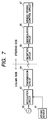
- Fig. 7 is an explanatory diagram showing the configuration of an embodiment implementing the conventional air-bag control apparatus.
- an air-bag sensor 61 for detecting a collision of the car
- a carrier generation means 62 for generating a carrier
- a modulation circuit 63 for modulating the carrier
- a transmission circuit 64 for transmitting a modulated carrier to the steering-wheel side.
- a reception circuit 65 On the steering-wheel side, on the other hand, there are provided a reception circuit 65, a demodulation circuit 66 and an air-bag driving control circuit 67.
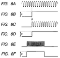
- the carrier generation means 62 on the column side generates typically a sinusoidal carrier like one shown in diagram A of Fig. 8 at normal times.
- This carrier is supplied to the modulation circuit 63 which is typically a balanced modulation circuit.
- the modulation circuit 63 does not output a modulated carrier. Only when a modulation signal is supplied to the modulation circuit 63 does the modulation circuit 63 output a modulated carrier.
- the air-bag sensor 61 detects a car collision at a point of time t0. In this case, the air-bag sensor 61 generates a predetermined voltage E as shown in diagram B of Fig. 8.
- the voltage E serves as a modulation signal supplied to the modulation circuit 63.
- the modulation circuit 63 modulates the carrier supplied thereto by the carrier generation circuit 62 starting from the point of time t0 as shown in diagram C of Fig. 8 and outputs a modulated carrier to the transmission circuit 64.
- the transmission circuit 64 transmits the modulated carrier received from the modulation circuit 63 to the reception circuit 65.
- a signal is transmitted from the transmission circuit 64 to the reception circuit 65 through typically a non-contact coupling means (or a non-contact coupler not shown in the figure).
- the reception circuit 65 passes on the modulated carrier received from the transmission circuit 64 to the demodulation circuit 66.
- the demodulation circuit 66 demodulates the modulated carrier received from the reception circuit 65 to produce a predetermined voltage E' shown in diagram D of Fig. 8 as a demodulated signal which is supplied to the air-bag driving control circuit 67.
- the air-bag driving control circuit 67 drives the air-bag unit in accordance with the demodulated signal.
- the other electronic equipment generates a variety of electromagnetic waves and radiates them.
- An electromagnetic wave generated by the other electronic equipment may be introduced onto a transmission line between, for example, the modulation circuit 63 and the demodulation circuit 66 in the configuration of the conventional embodiment in spite of the fact that the car does not collide with anything and, hence, the air-bag sensor 61 does not generate the predetermined voltage E.
- a noise signal like one shown in diagram E of Fig. 8 is supplied to the demodulation circuit 66 which then demodulates to inadvertently generate a demodulated signal like one shown in diagram F of Fig. 8.
- the demodulated signal is supplied to the air-bag driving control circuit 67.
- the air-bag driving control circuit 67 inadvertently drives the air-bag unit in accordance with the demodulated signal generated by the demodulation circuit 66 in spite of the fact that the demodulated signal is originated from an introduced noise signal.
- an air-bag control apparatus wherein first modulation means modulates a first carrier in accordance with a signal having a predetermined pattern from signal generation means to generate a first modulated signal and supply it to first demodulation means when collision detection means detects a car collision; the first demodulation means demodulates the first modulated signal to produce a first demodulated signal and supply it to signal comparison means; and the signal comparison means outputs an activation signal for activating an air bag only if the first demodulated signal matches the signal having the predetermined pattern.
- an air-bag control apparatus as in the first aspect, wherein the signal generation means comprises a plurality of switches for controlling car electronic equipment and a signal generation circuit for generating the signal having the predetermined pattern in accordance with an operating state of the switches.
- an air-bag control apparatus as in the second aspect, wherein the switches are installed on a steering wheel.
- an air-bag control apparatus as in the first, second or third aspect, wherein, the second modulation means modulates the second carrier in accordance with the signal having the predetermined pattern output from signal generation means to generate a second modulated signal and supply it to the second demodulation means; the second demodulation means demodulates the second modulated signal to produce a second signal; and the first modulation means modulates the first carrier in accordance with the second signal.
- an air-bag control apparatus as in the first aspect, wherein the signal generation means comprises a data retention unit for storing data having a predetermined format and a microcomputer, and the microcomputer reads out the data and generates the signal having the predetermined pattern.
- an air-bag control apparatus as in the fifth aspect, wherein two data retention units and two microcomputers are provided, and one of the data retention units and one of the microcomputers are provided on a column side, and one of the data retention units and one of the microcomputers are provided on a steering-wheel side.
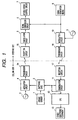
- Fig. 1 is a block diagram showing the configuration of an air-bag control apparatus provided by the present invention.
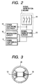
- Fig. 2 is a block diagram showing the configuration of a signal generation means employed in the air-bag control apparatus provided by the present invention.
- Fig. 3 is a diagram showing a layout of switches on a steering wheel of the air-bag control apparatus provided by the present invention.
- Fig. 5 is a block diagram showing the configuration of an air-bag control apparatus implemented by another embodiment of the present invention.
- Figs. 4 and 6 are diagrams each showing principal signals in a variety of components composing the air-bag control apparatus provided by the present invention.
- Figs. 1 and 2 As shown in Fig. 1, on the column side, there are provided, among other components, an air-bag sensor 1 for detecting a collision of the car, a switching gate 2 functioning as a gate, a first-carrier generation means 3 for generating a first carrier, a first modulation circuit 4 for modulating the first carrier, a first transmission circuit 14 for transmitting a first modulated carrier to the steering-wheel side, a second reception circuit 17 for receiving a signal from the steering-wheel side, a second demodulation circuit 11, a CPU 12 and other electronic equipment 13.
- an air-bag sensor 1 for detecting a collision of the car
- a switching gate 2 functioning as a gate
- a first-carrier generation means 3 for generating a first carrier
- a first modulation circuit 4 for modulating the first carrier
- a first transmission circuit 14 for transmitting a first modulated carrier to the steering-wheel side
- a second reception circuit 17 for receiving a signal from the steering-wheel side
- a first reception circuit 15 for receiving the first modulated carrier from the column side, a first demodulation circuit 5, a signal comparison circuit 6, an air-bag driving control circuit 7, a signal generation means 8, a second-carrier generation means 9 for generating a second carrier, a second modulation circuit 10 for modulating the second carrier, a second transmission circuit 16 for transmitting a second modulated carrier to the steering-wheel side.
- the signal generation means 8 has a plurality of switches 18 which are installed on the steering wheel 20 in a layout like typically one shown in Fig. 3. The switches 18 are used for controlling the other equipment 13.
- a signal generation circuit 19 generates a signal of a predetermined pattern in accordance with the operating state of the switches 18. The signal generated by the signal generation circuit 19 is supplied to the second modulation circuit 10 and the signal comparison circuit 6.
- the first carrier generation means 3 on the column side generates typically a sinusoidal carrier like one shown in diagram A of Fig. 4 at normal times.
- This carrier is supplied to the first modulation circuit 4 which is typically a balanced modulation circuit.
- the first modulation circuit 4 does not output a modulated carrier. Only when a modulation signal is supplied, the modulation circuit 4 output a modulated carrier.
- the signal generation means 8 continuously generates a signal having a predetermined pattern like one shown in diagram B of Fig. 4, supplying the signal to the signal comparison circuit 6 and the second modulation circuit 10.
- the second-carrier generation means 9 generates a carrier similar to the one which is generated by the first-carrier generation means 3 as shown in diagram A of Fig. 4.
- the carrier is supplied to the second modulation circuit 10 which is also typically a balanced modulation circuit.
- the second modulation circuit 10 does not output a modulated carrier. Only when a modulation signal is supplied, the modulation circuit 10 output a modulated carrier.
- the second modulation circuit 10 modulates the carrier by using the signal received from the signal generation circuit 8 as a modulation signal, outputting a result of modulation as a second modulated carrier like one shown in diagram C of Fig.
- a signal is transmitted from the second transmission circuit 16 to the second reception circuit 17 through typically a non-contact coupling means (or a non-contact coupler not shown in the figure).
- the second demodulation circuit 11 demodulates the second modulated carrier into a second demodulated signal like the one shown in diagram B of Fig. 4, outputting the demodulated signal to the switching gate 2.
- the air-bag sensor 1 detects a car collision at a point of time t0.
- the air-bag sensor 1 generates a predetermined voltage E as shown in diagram D of Fig. 4.
- the voltage E is supplied to the switching gate 2 to open the gate 2. With the switching gate 2 opened, the gate 2 passes on the demodulated signal with a predetermined pattern like one shown in diagram E of Fig. 4 from the second demodulation circuit 11 and outputs the demodulated signal to the first modulation circuit 4 as a modulation signal.
- the first modulation circuit 4 modulates the first carrier supplied thereto by the first-carrier generation means 3 starting from the point of time t0 as shown in diagram F of Fig. 4 and outputs a first modulated carrier to the first transmission circuit 14.
- the first transmission circuit 14 transmits the first modulated carrier received from the first modulation circuit 4 to the first reception circuit 15 on the steering-wheel side.
- a signal is transmitted from the first transmission circuit 14 to the first reception circuit 15 through typically a non-contact coupling means (or a non-contact coupler not shown in the figure).
- the first reception circuit 15 passes on the first modulated carrier received from the first transmission circuit 14 to the first demodulation circuit 5.
- the first demodulation circuit 5 demodulates the first modulated carrier received from the first reception circuit 15 to produce a first demodulated signal like one shown in diagram E of Fig. 4.
- the first demodulated signal is supplied to the signal comparison circuit 6.
- the signal comparison circuit 6 compares the first demodulated signal received from the first demodulation circuit 5 with the modulation signal received from the signal generation means 8 with timing determined by synchronization between the first demodulated signal and the modulation signal. Only if the first demodulated signal matches the modulation signal is a predetermined voltage E' serving as an activation signal like one shown in diagram G of Fig. 4 output to the air-bag driving control circuit 7.
- the air-bag driving control circuit 7 drives the air-bag unit in accordance with the predetermined voltage E'. If the signal comparison circuit 6 finds that the first demodulated signal does not match the modulation signal, on the other hand, the signal comparison circuit 6 does not generate the predetermined voltage E'. As a result, the air bag will not function incorrectly due to a noise signal. It should be noted that the second demodulated signal generated by the second demodulation circuit 11 is supplied to the CPU 12 too. The CPU 12 controls the operation of the other electronic equipment 13 in accordance with the second demodulated signal received from the second demodulation circuit 11.
- an air-bag sensor 1 used as a collision detection means for detecting a collision of the car
- a carrier generation means 30 used as a first-carrier generation means for generating a first carrier
- a modulation circuit 31 used as a first modulation circuit for modulating the first carrier
- a switching gate 2 functioning as a gate
- a modulation-signal generation circuit 35 for generating a modulation signal and a first data retention circuit 36 connected to the modulation-signal generation circuit 35
- a transmission circuit 32 for transmitting a modulated carrier to the steering-wheel side.
- the signal generation means 8 comprising the modulation-signal generation circuit 35 and the first data retention circuit 36 generates a modulation signal having a predetermined pattern.
- the modulation-signal generation circuit 35 is implemented by a microcomputer for reading out data with a predetermined format from the first data retention circuit 36 and generating the modulation signal having the predetermined pattern.
- a reception circuit 33 for receiving the modulated carrier from the column side, a demodulation circuit 34 used as a first demodulation means, a comparison-signal generation circuit 37 for generating a comparison signal, a second data retention circuit 38 connected to the comparison-signal generation circuit 37, a signal comparison circuit 6 for comparing a demodulated signal received from the demodulation circuit 34 and comparison-signal generation circuit 37, and an air-bag driving control circuit 7.
- the signal generation means 8 for generating a signal with a predetermined pattern comprises the comparison-signal generation circuit 37 and the second data retention circuit 38.
- the comparison-signal generation circuit 37 is implemented typically by a microcomputer for reading out data with a predetermined format from the second data retention circuit 38 and generating the comparison signal having the predetermined pattern.
- the data stored in the second data retention circuit 38 is the same as the data stored in the first data retention circuit 36 on the column side.
- the modulation signal generated by the modulation-signal generation circuit 35 has the same pattern as the comparison signal generated by the comparison-signal generation circuit 37.
- the function of the switching gate 2 may be included in the microcomputer or a CPU used as a typical means for implementing the modulation-signal generation circuit 35 as described above.
- the function of the signal comparison circuit 6 may be included in the microcomputer or a CPU used as a typical means for implementing the comparison-signal generation circuit 37 as described above.
- the carrier generation means 30 generates typically a sinusoidal carrier like one shown in diagram A of Fig. 6 at normal times. This carrier is supplied to the modulation circuit 31 which is typically a balanced modulation circuit. At normal times, however, the first modulation circuit 31 does not output a modulated carrier. Only when a modulation signal is supplied, the modulation circuit 31 output a modulated carrier. In the mean time, the modulation-signal generation circuit 35 reads out data with a predetermined format from the first data retention circuit 36 and outputs a modulation signal having a predetermined pattern like one shown in diagram B of Fig. 6 to the switching gate 2.
- the air-bag sensor 1 detects a car collision at a point of time t0.
- the air-bag sensor 1 generates a predetermined voltage E as shown in diagram C of Fig. 6.
- the voltage E is supplied to the switching gate 2 to open the gate 2.
- the gate 2 passes on a signal with a predetermined pattern like one shown in diagram D of Fig. 6 from the signal generation means 8 and outputs the signal to the modulation circuit 31 as a modulation signal.
- the modulation circuit 31 modulates the carrier supplied thereto by the carrier generation means 30 starting from the point of time t0 as shown in diagram E of Fig. 6 and outputs a modulated carrier to the transmission circuit 32.
- the transmission circuit 32 transmits the modulated carrier received from the modulation circuit 31 to the reception circuit 33 on the steering-wheel side.
- a signal is transmitted from the transmission circuit 32 to the reception circuit 33 through typically a non-contact coupling means (or a non-contact coupler not shown in the figure).
- the reception circuit 33 passes on the modulated carrier received from the transmission circuit 32 to the demodulation circuit 34.
- the demodulation circuit 34 demodulates the modulated carrier received from the reception circuit 33 to produce a demodulated signal like one shown in diagram D of Fig. 6.
- the demodulated signal is then supplied to the signal comparison circuit 6.
- the comparison-signal generation circuit 37 reads out data with a predetermined format from the second data retention circuit 38 and outputs the comparison signal having a predetermined pattern like the one shown in diagram B of Fig. 6 to the signal comparison circuit 6.
- the signal comparison circuit 6 compares the demodulated signal received from the demodulation circuit 34 with the comparison signal received from the comparison-signal generation circuit 37 with timing determined by synchronization between the demodulated signal and the comparison signal.
- the air-bag driving control circuit 7 drives the air-bag unit in accordance with the predetermined voltage E'.
- AM modulation The technique for modulating a carrier in the air-bag control apparatus described above is AM modulation. It should be noted that PM-modulation and FM-modulation techniques are of course capable of providing the same effects.
- the air-bag control apparatus provided by the present invention exhibits the following effects.
- an air-bag control apparatus wherein first modulation means modulates a first carrier in accordance with a signal having a predetermined pattern from signal generation means to generate a first modulated signal and supply it to first demodulation means when collision detection means detects a car collision; the first demodulation means demodulates the first modulated signal to produce a first demodulated signal and supply it to signal comparison means; and the signal comparison means outputs an activation signal for activating an air bag only if the first demodulated signal matches the signal having the predetermined pattern.
- the activation signal is not generated by a noise signal caused by an effect of an electromagnetic wave originated from other electronic equipment.
- a signal generation means comprises a plurality of switches for controlling car electronic equipment and a signal generation circuit for generating the signal having the predetermined pattern in accordance with an operating state of the switches.
- an air-bag control apparatus as in the second aspect wherein the switches are installed on a steering wheel.
- an air-bag control apparatus as in the first, second or third aspect wherein, a signal having the predetermined pattern output from the signal generation means is supplied to the first modulation means via a second modulation means and second demodulation means, the first modulation means modulates the first carrier in accordance with the signal demodulated by the second demodulation means.
- the signal generated by the signal generation means with the predetermined pattern is hardly affected by an electromagnetic wave generated by other electronic equipment.
- the signal having the predetermined pattern can be transmitted with a high degree of precision.
- an air-bag control apparatus as in the first aspect wherein; in the signal generation means, a microcomputer reads out the data and generates the signal having the predetermined pattern.
- the signal is generated by the microcomputer with always the same pattern.
- the signal can be transmitted with a high degree of precision.
- an air-bag control apparatus as in the fifth aspect wherein, two data retention units and two microcomputers are provided, and one of the data retention units and one of the microcomputers are provided on a column side, and one of the data retention units and one of the microcomputers are provided on a steering-wheel side.
Landscapes
- Engineering & Computer Science (AREA)
- Mechanical Engineering (AREA)
- Air Bags (AREA)
Abstract
Description
- In general, the present invention relates to an air-bag control apparatus provided for controlling an air-bag unit. More particularly, the present invention relates to an air-bag control apparatus that is hardly affected by noise introduced onto a line for transmitting a signal driving an air-bag unit, being capable of avoiding a malfunction of the air-bag unit.
- In recent years, there are an increasing number of cars in each of which an air-bag unit is provided on a steering wheel to protect the passengers against a shock caused by a car collision in the event of an accident.
- Fig. 7 is an explanatory diagram showing the configuration of an embodiment implementing the conventional air-bag control apparatus. As shown in the figure, on the column side, there are provided an air-
bag sensor 61 for detecting a collision of the car, a carrier generation means 62 for generating a carrier, amodulation circuit 63 for modulating the carrier and atransmission circuit 64 for transmitting a modulated carrier to the steering-wheel side. On the steering-wheel side, on the other hand, there are provided areception circuit 65, ademodulation circuit 66 and an air-bagdriving control circuit 67. - Next, the operation of the embodiment implementing the conventional air-bag control apparatus is explained by referring to Figs. 7 and 8. The carrier generation means 62 on the column side generates typically a sinusoidal carrier like one shown in diagram A of Fig. 8 at normal times. This carrier is supplied to the
modulation circuit 63 which is typically a balanced modulation circuit. At normal times, however, themodulation circuit 63 does not output a modulated carrier. Only when a modulation signal is supplied to themodulation circuit 63 does themodulation circuit 63 output a modulated carrier. Assume that the air-bag sensor 61 detects a car collision at a point of time t0. In this case, the air-bag sensor 61 generates a predetermined voltage E as shown in diagram B of Fig. 8. The voltage E serves as a modulation signal supplied to themodulation circuit 63. As a result, themodulation circuit 63 modulates the carrier supplied thereto by thecarrier generation circuit 62 starting from the point of time t0 as shown in diagram C of Fig. 8 and outputs a modulated carrier to thetransmission circuit 64. Thetransmission circuit 64 transmits the modulated carrier received from themodulation circuit 63 to thereception circuit 65. A signal is transmitted from thetransmission circuit 64 to thereception circuit 65 through typically a non-contact coupling means (or a non-contact coupler not shown in the figure). Thereception circuit 65 passes on the modulated carrier received from thetransmission circuit 64 to thedemodulation circuit 66. Thedemodulation circuit 66 demodulates the modulated carrier received from thereception circuit 65 to produce a predetermined voltage E' shown in diagram D of Fig. 8 as a demodulated signal which is supplied to the air-bagdriving control circuit 67. The air-bagdriving control circuit 67 drives the air-bag unit in accordance with the demodulated signal. - By the way, in recent years, there are many other pieces of electronic equipment installed in a car. The other electronic equipment generates a variety of electromagnetic waves and radiates them. An electromagnetic wave generated by the other electronic equipment may be introduced onto a transmission line between, for example, the
modulation circuit 63 and thedemodulation circuit 66 in the configuration of the conventional embodiment in spite of the fact that the car does not collide with anything and, hence, the air-bag sensor 61 does not generate the predetermined voltage E. When such an electromagnetic wave is introduced onto the transmission line, a noise signal like one shown in diagram E of Fig. 8 is supplied to thedemodulation circuit 66 which then demodulates to inadvertently generate a demodulated signal like one shown in diagram F of Fig. 8. The demodulated signal is supplied to the air-bagdriving control circuit 67. When this happens, the air-bagdriving control circuit 67 inadvertently drives the air-bag unit in accordance with the demodulated signal generated by thedemodulation circuit 66 in spite of the fact that the demodulated signal is originated from an introduced noise signal. - When the air-bag unit is driven in spite of the fact that no accident such as a car collision takes place, the driver's field of vision is blocked and the driving is disturbed.
- It is thus an object of the present invention to avoid a malfunction of an air-bag unit caused by an electromagnetic wave generated by various kinds of electronic equipment.
- According to a first aspect of the present invention, there is provided an air-bag control apparatus: wherein first modulation means modulates a first carrier in accordance with a signal having a predetermined pattern from signal generation means to generate a first modulated signal and supply it to first demodulation means when collision detection means detects a car collision; the first demodulation means demodulates the first modulated signal to produce a first demodulated signal and supply it to signal comparison means; and the signal comparison means outputs an activation signal for activating an air bag only if the first demodulated signal matches the signal having the predetermined pattern.
- According to a second aspect of the present invention, there is provided an air-bag control apparatus as in the first aspect, wherein the signal generation means comprises a plurality of switches for controlling car electronic equipment and a signal generation circuit for generating the signal having the predetermined pattern in accordance with an operating state of the switches.
- According to a third aspect of the present invention, there is provided an air-bag control apparatus as in the second aspect, wherein the switches are installed on a steering wheel.
- According to a fourth aspect of the present invention, there is provided an air-bag control apparatus as in the first, second or third aspect, wherein, the second modulation means modulates the second carrier in accordance with the signal having the predetermined pattern output from signal generation means to generate a second modulated signal and supply it to the second demodulation means; the second demodulation means demodulates the second modulated signal to produce a second signal; and the first modulation means modulates the first carrier in accordance with the second signal.
- According to a fifth aspect of the present invention, there is provided an air-bag control apparatus as in the first aspect, wherein the signal generation means comprises a data retention unit for storing data having a predetermined format and a microcomputer, and the microcomputer reads out the data and generates the signal having the predetermined pattern.
- According to a sixth aspect of the present invention, there is provided an air-bag control apparatus as in the fifth aspect, wherein two data retention units and two microcomputers are provided, and one of the data retention units and one of the microcomputers are provided on a column side, and one of the data retention units and one of the microcomputers are provided on a steering-wheel side.
-
- Fig. 1 is a block diagram showing one embodiment of the configuration of an air-bag control apparatus provided by the present invention;
- Fig. 2 is a block diagram showing another embodiment of the configuration of an air-bag control apparatus provided by the present invention;
- Fig. 3 is a diagram showing an embodiment of a layout of switches of the air-bag control apparatus provided by the present invention;
- Fig. 4 is diagrams showing signals at main components of the embodiment implementing the air-bag control apparatus provided by the present invention as shown in Fig. 1;
- Fig. 5 is a block diagram showing the configuration of a signal generation means of the air-bag control apparatus implemented by another embodiment of the present invention;
- Fig. 6 is diagrams showing signals at main components of the embodiment implementing the air-bag control apparatus provided by the present invention as shown in Fig. 5;
- Fig. 7 is a block diagram showing the conventional air-bag control apparatus; and
- Fig. 8 is diagrams showing signals at main components of the conventional air-bag control apparatus shown in Fig. 7.
-
- The present invention will become more apparent from a careful study of the following detailed description of some preferred embodiments with reference to the accompanying diagrams. Fig. 1 is a block diagram showing the configuration of an air-bag control apparatus provided by the present invention. Fig. 2 is a block diagram showing the configuration of a signal generation means employed in the air-bag control apparatus provided by the present invention. Fig. 3 is a diagram showing a layout of switches on a steering wheel of the air-bag control apparatus provided by the present invention. Fig. 5 is a block diagram showing the configuration of an air-bag control apparatus implemented by another embodiment of the present invention. Figs. 4 and 6 are diagrams each showing principal signals in a variety of components composing the air-bag control apparatus provided by the present invention.
- First of all, the configuration of an embodiment of the present invention is explained by referring to Figs. 1 and 2. As shown in Fig. 1, on the column side, there are provided, among other components, an air-
bag sensor 1 for detecting a collision of the car, a switching gate 2 functioning as a gate, a first-carrier generation means 3 for generating a first carrier, a first modulation circuit 4 for modulating the first carrier, afirst transmission circuit 14 for transmitting a first modulated carrier to the steering-wheel side, a second reception circuit 17 for receiving a signal from the steering-wheel side, asecond demodulation circuit 11, aCPU 12 and otherelectronic equipment 13. On the steering-wheel side, on the other hand, there are provided, among other components, afirst reception circuit 15 for receiving the first modulated carrier from the column side, afirst demodulation circuit 5, a signal comparison circuit 6, an air-bag driving control circuit 7, a signal generation means 8, a second-carrier generation means 9 for generating a second carrier, asecond modulation circuit 10 for modulating the second carrier, asecond transmission circuit 16 for transmitting a second modulated carrier to the steering-wheel side. As shown in Fig. 2, the signal generation means 8 has a plurality ofswitches 18 which are installed on thesteering wheel 20 in a layout like typically one shown in Fig. 3. Theswitches 18 are used for controlling theother equipment 13. In addition, asignal generation circuit 19 generates a signal of a predetermined pattern in accordance with the operating state of theswitches 18. The signal generated by thesignal generation circuit 19 is supplied to thesecond modulation circuit 10 and the signal comparison circuit 6. - Next, the operation of this embodiment of the present invention is explained by referring to Figs. 1 and 4. The first carrier generation means 3 on the column side generates typically a sinusoidal carrier like one shown in diagram A of Fig. 4 at normal times. This carrier is supplied to the first modulation circuit 4 which is typically a balanced modulation circuit. At normal times, however, the first modulation circuit 4 does not output a modulated carrier. Only when a modulation signal is supplied, the modulation circuit 4 output a modulated carrier. On the steering-wheel side, on the other hand, the signal generation means 8 continuously generates a signal having a predetermined pattern like one shown in diagram B of Fig. 4, supplying the signal to the signal comparison circuit 6 and the
second modulation circuit 10. At normal times, the second-carrier generation means 9 generates a carrier similar to the one which is generated by the first-carrier generation means 3 as shown in diagram A of Fig. 4. The carrier is supplied to thesecond modulation circuit 10 which is also typically a balanced modulation circuit. At normal times, however, thesecond modulation circuit 10 does not output a modulated carrier. Only when a modulation signal is supplied, themodulation circuit 10 output a modulated carrier. Thesecond modulation circuit 10 modulates the carrier by using the signal received from thesignal generation circuit 8 as a modulation signal, outputting a result of modulation as a second modulated carrier like one shown in diagram C of Fig. 4 to thesecond demodulation circuit 11 on the column side by way of thesecond transmission circuit 16 on the steering-wheel side and the second reception circuit 17 on the column side. A signal is transmitted from thesecond transmission circuit 16 to the second reception circuit 17 through typically a non-contact coupling means (or a non-contact coupler not shown in the figure). - The
second demodulation circuit 11 demodulates the second modulated carrier into a second demodulated signal like the one shown in diagram B of Fig. 4, outputting the demodulated signal to the switching gate 2. Assume that the air-bag sensor 1 detects a car collision at a point of time t0. In this case, the air-bag sensor 1 generates a predetermined voltage E as shown in diagram D of Fig. 4. The voltage E is supplied to the switching gate 2 to open the gate 2. With the switching gate 2 opened, the gate 2 passes on the demodulated signal with a predetermined pattern like one shown in diagram E of Fig. 4 from thesecond demodulation circuit 11 and outputs the demodulated signal to the first modulation circuit 4 as a modulation signal. As a result, the first modulation circuit 4 modulates the first carrier supplied thereto by the first-carrier generation means 3 starting from the point of time t0 as shown in diagram F of Fig. 4 and outputs a first modulated carrier to thefirst transmission circuit 14. Thefirst transmission circuit 14 transmits the first modulated carrier received from the first modulation circuit 4 to thefirst reception circuit 15 on the steering-wheel side. A signal is transmitted from thefirst transmission circuit 14 to thefirst reception circuit 15 through typically a non-contact coupling means (or a non-contact coupler not shown in the figure). - The
first reception circuit 15 passes on the first modulated carrier received from thefirst transmission circuit 14 to thefirst demodulation circuit 5. Thefirst demodulation circuit 5 demodulates the first modulated carrier received from thefirst reception circuit 15 to produce a first demodulated signal like one shown in diagram E of Fig. 4. The first demodulated signal is supplied to the signal comparison circuit 6. The signal comparison circuit 6 compares the first demodulated signal received from thefirst demodulation circuit 5 with the modulation signal received from the signal generation means 8 with timing determined by synchronization between the first demodulated signal and the modulation signal. Only if the first demodulated signal matches the modulation signal is a predetermined voltage E' serving as an activation signal like one shown in diagram G of Fig. 4 output to the air-bag driving control circuit 7. The air-bag driving control circuit 7 drives the air-bag unit in accordance with the predetermined voltage E'. If the signal comparison circuit 6 finds that the first demodulated signal does not match the modulation signal, on the other hand, the signal comparison circuit 6 does not generate the predetermined voltage E'. As a result, the air bag will not function incorrectly due to a noise signal. It should be noted that the second demodulated signal generated by thesecond demodulation circuit 11 is supplied to theCPU 12 too. TheCPU 12 controls the operation of the otherelectronic equipment 13 in accordance with the second demodulated signal received from thesecond demodulation circuit 11. - Next, the configuration of another embodiment of the present invention is explained by referring to Fig. 5. As shown in Fig. 5, on the column side, there are provided an air-
bag sensor 1 used as a collision detection means for detecting a collision of the car, a carrier generation means 30 used as a first-carrier generation means for generating a first carrier, amodulation circuit 31 used as a first modulation circuit for modulating the first carrier, a switching gate 2 functioning as a gate, a modulation-signal generation circuit 35 for generating a modulation signal and a firstdata retention circuit 36 connected to the modulation-signal generation circuit 35, and atransmission circuit 32 for transmitting a modulated carrier to the steering-wheel side. The signal generation means 8 comprising the modulation-signal generation circuit 35 and the firstdata retention circuit 36 generates a modulation signal having a predetermined pattern. Typically, the modulation-signal generation circuit 35 is implemented by a microcomputer for reading out data with a predetermined format from the firstdata retention circuit 36 and generating the modulation signal having the predetermined pattern. - On the steering-wheel side, on the other hand, there are provided a
reception circuit 33 for receiving the modulated carrier from the column side, ademodulation circuit 34 used as a first demodulation means, a comparison-signal generation circuit 37 for generating a comparison signal, a seconddata retention circuit 38 connected to the comparison-signal generation circuit 37, a signal comparison circuit 6 for comparing a demodulated signal received from thedemodulation circuit 34 and comparison-signal generation circuit 37, and an air-bag driving control circuit 7. As described above, the signal generation means 8 for generating a signal with a predetermined pattern comprises the comparison-signal generation circuit 37 and the seconddata retention circuit 38. Much like the modulation-signal generation circuit 35, the comparison-signal generation circuit 37 is implemented typically by a microcomputer for reading out data with a predetermined format from the seconddata retention circuit 38 and generating the comparison signal having the predetermined pattern. The data stored in the seconddata retention circuit 38 is the same as the data stored in the firstdata retention circuit 36 on the column side. Thus, the modulation signal generated by the modulation-signal generation circuit 35 has the same pattern as the comparison signal generated by the comparison-signal generation circuit 37. In addition, the function of the switching gate 2 may be included in the microcomputer or a CPU used as a typical means for implementing the modulation-signal generation circuit 35 as described above. Similarly, the function of the signal comparison circuit 6 may be included in the microcomputer or a CPU used as a typical means for implementing the comparison-signal generation circuit 37 as described above. - Next, the operation of the other embodiment of the present invention is explained by referring to Figs. 5 and 6. The carrier generation means 30 generates typically a sinusoidal carrier like one shown in diagram A of Fig. 6 at normal times. This carrier is supplied to the
modulation circuit 31 which is typically a balanced modulation circuit. At normal times, however, thefirst modulation circuit 31 does not output a modulated carrier. Only when a modulation signal is supplied, themodulation circuit 31 output a modulated carrier. In the mean time, the modulation-signal generation circuit 35 reads out data with a predetermined format from the firstdata retention circuit 36 and outputs a modulation signal having a predetermined pattern like one shown in diagram B of Fig. 6 to the switching gate 2. Assume that the air-bag sensor 1 detects a car collision at a point of time t0. In this case, the air-bag sensor 1 generates a predetermined voltage E as shown in diagram C of Fig. 6. The voltage E is supplied to the switching gate 2 to open the gate 2. With the switching gate 2 opened, the gate 2 passes on a signal with a predetermined pattern like one shown in diagram D of Fig. 6 from the signal generation means 8 and outputs the signal to themodulation circuit 31 as a modulation signal. As a result, themodulation circuit 31 modulates the carrier supplied thereto by the carrier generation means 30 starting from the point of time t0 as shown in diagram E of Fig. 6 and outputs a modulated carrier to thetransmission circuit 32. Thetransmission circuit 32 transmits the modulated carrier received from themodulation circuit 31 to thereception circuit 33 on the steering-wheel side. A signal is transmitted from thetransmission circuit 32 to thereception circuit 33 through typically a non-contact coupling means (or a non-contact coupler not shown in the figure). - The
reception circuit 33 passes on the modulated carrier received from thetransmission circuit 32 to thedemodulation circuit 34. Thedemodulation circuit 34 demodulates the modulated carrier received from thereception circuit 33 to produce a demodulated signal like one shown in diagram D of Fig. 6. The demodulated signal is then supplied to the signal comparison circuit 6. In the mean time, the comparison-signal generation circuit 37 reads out data with a predetermined format from the seconddata retention circuit 38 and outputs the comparison signal having a predetermined pattern like the one shown in diagram B of Fig. 6 to the signal comparison circuit 6. The signal comparison circuit 6 compares the demodulated signal received from thedemodulation circuit 34 with the comparison signal received from the comparison-signal generation circuit 37 with timing determined by synchronization between the demodulated signal and the comparison signal. Only if the demodulated signal matches the comparison signal is a predetermined voltage E' serving as an activation signal like one shown in diagram F of Fig. 6 output to the air-bag driving control circuit 7. The air-bag driving control circuit 7 drives the air-bag unit in accordance with the predetermined voltage E'. - The technique for modulating a carrier in the air-bag control apparatus described above is AM modulation. It should be noted that PM-modulation and FM-modulation techniques are of course capable of providing the same effects.
- The air-bag control apparatus provided by the present invention exhibits the following effects.
- According to a first aspect of the present invention, there is provided an air-bag control apparatus, wherein first modulation means modulates a first carrier in accordance with a signal having a predetermined pattern from signal generation means to generate a first modulated signal and supply it to first demodulation means when collision detection means detects a car collision; the first demodulation means demodulates the first modulated signal to produce a first demodulated signal and supply it to signal comparison means; and the signal comparison means outputs an activation signal for activating an air bag only if the first demodulated signal matches the signal having the predetermined pattern.
- As a result, the activation signal is not generated by a noise signal caused by an effect of an electromagnetic wave originated from other electronic equipment.
- According to a second aspect of the present invention, there is provided an air-bag control apparatus as in the first aspect wherein a signal generation means comprises a plurality of switches for controlling car electronic equipment and a signal generation circuit for generating the signal having the predetermined pattern in accordance with an operating state of the switches.
- As a result, since the switches used for other electronic equipment are used, it is possible to generate the signal having the predetermined pattern without the need to provide a new switch.
- According to a third aspect of the present invention, there is provided an air-bag control apparatus as in the second aspect wherein the switches are installed on a steering wheel. As a result, since the switches are installed on the steering wheel in front of the eyes of the driver, the switches can be operated with ease without the need for the driver to turn the driver's eyes away from the line of vision.
- According to a fourth aspect of the present invention, there is provided an air-bag control apparatus as in the first, second or third aspect wherein, a signal having the predetermined pattern output from the signal generation means is supplied to the first modulation means via a second modulation means and second demodulation means, the first modulation means modulates the first carrier in accordance with the signal demodulated by the second demodulation means.
- Thus, the signal generated by the signal generation means with the predetermined pattern is hardly affected by an electromagnetic wave generated by other electronic equipment. As a result, the signal having the predetermined pattern can be transmitted with a high degree of precision.
- According to a fifth aspect of the present invention, there is provided an air-bag control apparatus as in the first aspect wherein; in the signal generation means, a microcomputer reads out the data and generates the signal having the predetermined pattern.
- As a result, the signal is generated by the microcomputer with always the same pattern. In addition, by setting the data stored in the data retention means properly for transmission of the signal in advance, the signal can be transmitted with a high degree of precision.
- According to a sixth aspect of the present invention, there is provided an air-bag control apparatus as in the fifth aspect wherein, two data retention units and two microcomputers are provided, and one of the data retention units and one of the microcomputers are provided on a column side, and one of the data retention units and one of the microcomputers are provided on a steering-wheel side.
- As a result, since a signal with a predetermined format can be generated on the column side and the steering-wheel side, it is not necessary to provide a transmission line for transmitting the signal having the predetermined pattern.
Claims (6)
- An air-bag control apparatus comprising:collision detection means for detecting a car collision;first-carrier generation means for generating a first carrier;first modulation means for inputting the first carrier;signal generation means for generating a signal having a predetermined pattern;first demodulation means; andsignal comparison means,
wherein:the first modulation means modulates the first carrier in accordance with the signal having the predetermined pattern to generate a first modulated signal and supply it to the first demodulation means when the collision detection means detects a car collision;the first demodulation means demodulates the first modulated signal to produce a first demodulated signal and supply it to the signal comparison means; andthe signal comparison means outputs an activation signal for activating an air bag only if the first demodulated signal matches the signal having the predetermined pattern. - An air-bag control apparatus according to claim 1 wherein the signal generation means comprises a plurality of switches for controlling car electronic equipment and a signal generation circuit for generating the signal having the predetermined pattern in accordance with an operating state of the switches.
- An air-bag control apparatus according to claim 2 wherein the switches are installed on a steering wheel.
- An air-bag control apparatus according to any of the claims 1 to 3, the apparatus further including:a second modulation means for inputting the second carrier; anda second demodulation means,
wherein,the second modulation means modulates the second carrier in accordance with the signal having the predetermined pattern output from the signal generation means to generate a second modulated signal and supply it to the second demodulation means;the second demodulation means demodulates the second modulated signal to produce a second signal having the same pattern as the signal having the predetermined pattern; andthe first modulation means modulates the first carrier in accordance with the second signal. - An air-bag control apparatus according to any of the claims 1 to 4, wherein:the signal generation means comprises a data retention unit for storing data having a predetermined format and a microcomputer; andthe microcomputer reads out the data and generates the signal having the predetermined pattern.
- An air-bag control apparatus according to claim 5, wherein two data retention units and two microcomputers are provided, and one of the two data retention units and one of the two microcomputers are provided on a column side, and one of the two data retention units and one of the two microcomputers are provided on a steering-wheel side.
Applications Claiming Priority (2)
| Application Number | Priority Date | Filing Date | Title |
|---|---|---|---|
| JP8827199 | 1999-03-30 | ||
| JP11088271A JP2000280856A (en) | 1999-03-30 | 1999-03-30 | Air bag control device |
Publications (2)
| Publication Number | Publication Date |
|---|---|
| EP1040967A1 true EP1040967A1 (en) | 2000-10-04 |
| EP1040967B1 EP1040967B1 (en) | 2004-07-28 |
Family
ID=13938244
Family Applications (1)
| Application Number | Title | Priority Date | Filing Date |
|---|---|---|---|
| EP00106751A Expired - Lifetime EP1040967B1 (en) | 1999-03-30 | 2000-03-29 | Air-bag control apparatus |
Country Status (4)
| Country | Link |
|---|---|
| US (1) | US6441511B1 (en) |
| EP (1) | EP1040967B1 (en) |
| JP (1) | JP2000280856A (en) |
| DE (1) | DE60012393T2 (en) |
Cited By (2)
| Publication number | Priority date | Publication date | Assignee | Title |
|---|---|---|---|---|
| EP1243478A1 (en) * | 2001-03-21 | 2002-09-25 | Nissan Motor Company, Limited | Occupant restraint system and method for operating the same |
| DE102005003577A1 (en) * | 2005-01-25 | 2006-08-10 | Auto Kabel Managementgesellschaft Mbh | Battery pole connection device for vehicle, has control device attached to short-circuit detecting unit that detects short-circuits, such that current interruption takes place during occurrence of definable short-circuit condition |
Families Citing this family (4)
| Publication number | Priority date | Publication date | Assignee | Title |
|---|---|---|---|---|
| DE10046695B4 (en) * | 2000-09-21 | 2005-02-17 | Robert Bosch Gmbh | Device for the wireless transmission of a triggering signal |
| DE10259546A1 (en) * | 2002-12-19 | 2004-07-01 | Robert Bosch Gmbh | Device for wireless transmission of a trigger signal |
| CN101632141B (en) * | 2006-12-20 | 2012-05-09 | 模拟技术公司 | Contactless Rotary Power Transfer System |
| FI129165B (en) * | 2016-02-04 | 2021-08-31 | Rolls Royce Oy Ab | Contactless power transmission |
Citations (3)
| Publication number | Priority date | Publication date | Assignee | Title |
|---|---|---|---|---|
| EP0482234A1 (en) * | 1990-10-24 | 1992-04-29 | ROBOMATIC S.a.s. | Electromagnetic signal transmission system on a road vehicle |
| DE19541998A1 (en) * | 1995-11-10 | 1997-05-15 | Bosch Gmbh Robert | Airbag system for a motor vehicle |
| DE19829730A1 (en) * | 1998-07-03 | 2000-01-20 | Mannesmann Vdo Ag | Electrical termination device for connecting elements within automobile steering wheel to onboard electrical network |
Family Cites Families (5)
| Publication number | Priority date | Publication date | Assignee | Title |
|---|---|---|---|---|
| US5636863A (en) * | 1994-04-26 | 1997-06-10 | Eaton Corporation | Vehicle steering column control system |
| US6012736A (en) * | 1994-04-26 | 2000-01-11 | Eaton Corporation | Vehicle steering column control system |
| DE59700556D1 (en) * | 1996-03-08 | 1999-11-18 | Siemens Ag | ARRANGEMENT FOR CONTROLLING A RESTRAINT MODULE, IN PARTICULAR FOR A MOTOR VEHICLE |
| DE19737506C1 (en) * | 1997-08-28 | 1998-11-12 | Sican F & E Gmbh Sibet | Automobile passenger restraint system release control |
| US6121692A (en) * | 1999-09-14 | 2000-09-19 | Eaton Corporation | Circuit and method for establishing two-way communication between the steering column and the steering wheel of a vehicle |
-
1999
- 1999-03-30 JP JP11088271A patent/JP2000280856A/en not_active Withdrawn
-
2000
- 2000-03-28 US US09/536,955 patent/US6441511B1/en not_active Expired - Fee Related
- 2000-03-29 EP EP00106751A patent/EP1040967B1/en not_active Expired - Lifetime
- 2000-03-29 DE DE60012393T patent/DE60012393T2/en not_active Expired - Fee Related
Patent Citations (3)
| Publication number | Priority date | Publication date | Assignee | Title |
|---|---|---|---|---|
| EP0482234A1 (en) * | 1990-10-24 | 1992-04-29 | ROBOMATIC S.a.s. | Electromagnetic signal transmission system on a road vehicle |
| DE19541998A1 (en) * | 1995-11-10 | 1997-05-15 | Bosch Gmbh Robert | Airbag system for a motor vehicle |
| DE19829730A1 (en) * | 1998-07-03 | 2000-01-20 | Mannesmann Vdo Ag | Electrical termination device for connecting elements within automobile steering wheel to onboard electrical network |
Cited By (4)
| Publication number | Priority date | Publication date | Assignee | Title |
|---|---|---|---|---|
| EP1243478A1 (en) * | 2001-03-21 | 2002-09-25 | Nissan Motor Company, Limited | Occupant restraint system and method for operating the same |
| US6722462B2 (en) | 2001-03-21 | 2004-04-20 | Nissan Motor Co., Ltd. | Occupant restraint system and method for operating the same |
| DE102005003577A1 (en) * | 2005-01-25 | 2006-08-10 | Auto Kabel Managementgesellschaft Mbh | Battery pole connection device for vehicle, has control device attached to short-circuit detecting unit that detects short-circuits, such that current interruption takes place during occurrence of definable short-circuit condition |
| DE102005003577B4 (en) * | 2005-01-25 | 2008-06-26 | Auto Kabel Managementgesellschaft Mbh | Battery pole connection device with short-circuit detector |
Also Published As
| Publication number | Publication date |
|---|---|
| DE60012393T2 (en) | 2005-07-21 |
| JP2000280856A (en) | 2000-10-10 |
| EP1040967B1 (en) | 2004-07-28 |
| DE60012393D1 (en) | 2004-09-02 |
| US6441511B1 (en) | 2002-08-27 |
Similar Documents
| Publication | Publication Date | Title |
|---|---|---|
| US6805375B2 (en) | Device for wireless transmission of a trigger signal | |
| US20070233919A1 (en) | Communication apparatus | |
| US6710470B2 (en) | Device for the wireless transmission of a tripping signal for a restraint system | |
| KR100343268B1 (en) | Method and device for controlling data transmission between two modules located in a motor vehicle | |
| JPH1071927A (en) | Method for connecting a state recognition device of a passive safety system for motor vehicles to a control unit | |
| US6441511B1 (en) | Air-bag control apparatus for avoiding air bag unit malfunctions caused by electromagnetic waves | |
| US6045156A (en) | Supplement restraint system having deployment inhibit apparatus | |
| KR100551297B1 (en) | Airbag system with seat belt warning | |
| US20020027347A1 (en) | Bidirectional data transmission system, units for the same, airbag device and seat belt retractor | |
| US6429774B1 (en) | Evaluating unit for a device for detecting objects, in particular for monitoring the interior of a motor vehicle, as well as a device for detecting objects having such an evaluating unit and a method for controlling such a device | |
| JP3719371B2 (en) | Vehicle occupant protection system | |
| US20070115454A1 (en) | Environmental detection system with two spaced-apart emitters and receivers | |
| US6285937B1 (en) | Seatbelt drive interlock system | |
| JPH11115760A (en) | Digital atc device | |
| KR101039428B1 (en) | Wireless transmission apparatus of vehicle and antenna driving method using same | |
| JP3906566B2 (en) | Collision determination device for vehicle occupant protection system | |
| KR100476570B1 (en) | Device for controlling electronic airbag of frame body car | |
| KR101039429B1 (en) | Wireless transmission device for a vehicle having a plurality of low frequency antennas | |
| KR960013791A (en) | Test equipment for on-board signaling device for railway vehicle | |
| US20040245752A1 (en) | Supplemental restraint controller | |
| KR100242196B1 (en) | Car Airbag Power Supply | |
| KR20000046258A (en) | Wireless remote firing system of air bag for vehicle | |
| JPS5946865A (en) | Method for preventing mis-connection of connector cable | |
| JPH11348729A (en) | Vehicle occupant protection system | |
| KR980001355A (en) | Vehicle warning device |
Legal Events
| Date | Code | Title | Description |
|---|---|---|---|
| PUAI | Public reference made under article 153(3) epc to a published international application that has entered the european phase |
Free format text: ORIGINAL CODE: 0009012 |
|
| AK | Designated contracting states |
Kind code of ref document: A1 Designated state(s): DE FR GB SE |
|
| AX | Request for extension of the european patent |
Free format text: AL;LT;LV;MK;RO;SI |
|
| 17P | Request for examination filed |
Effective date: 20010403 |
|
| AKX | Designation fees paid |
Free format text: DE FR GB SE |
|
| 17Q | First examination report despatched |
Effective date: 20020912 |
|
| GRAP | Despatch of communication of intention to grant a patent |
Free format text: ORIGINAL CODE: EPIDOSNIGR1 |
|
| GRAS | Grant fee paid |
Free format text: ORIGINAL CODE: EPIDOSNIGR3 |
|
| GRAA | (expected) grant |
Free format text: ORIGINAL CODE: 0009210 |
|
| AK | Designated contracting states |
Kind code of ref document: B1 Designated state(s): DE FR GB SE |
|
| REG | Reference to a national code |
Ref country code: GB Ref legal event code: FG4D |
|
| REF | Corresponds to: |
Ref document number: 60012393 Country of ref document: DE Date of ref document: 20040902 Kind code of ref document: P |
|
| REG | Reference to a national code |
Ref country code: SE Ref legal event code: TRGR |
|
| ET | Fr: translation filed | ||
| PGFP | Annual fee paid to national office [announced via postgrant information from national office to epo] |
Ref country code: SE Payment date: 20050323 Year of fee payment: 6 |
|
| PLBE | No opposition filed within time limit |
Free format text: ORIGINAL CODE: 0009261 |
|
| STAA | Information on the status of an ep patent application or granted ep patent |
Free format text: STATUS: NO OPPOSITION FILED WITHIN TIME LIMIT |
|
| 26N | No opposition filed |
Effective date: 20050429 |
|
| PG25 | Lapsed in a contracting state [announced via postgrant information from national office to epo] |
Ref country code: SE Free format text: LAPSE BECAUSE OF NON-PAYMENT OF DUE FEES Effective date: 20060330 |
|
| EUG | Se: european patent has lapsed | ||
| PGFP | Annual fee paid to national office [announced via postgrant information from national office to epo] |
Ref country code: GB Payment date: 20070323 Year of fee payment: 8 |
|
| PGFP | Annual fee paid to national office [announced via postgrant information from national office to epo] |
Ref country code: DE Payment date: 20070522 Year of fee payment: 8 |
|
| PGFP | Annual fee paid to national office [announced via postgrant information from national office to epo] |
Ref country code: FR Payment date: 20070321 Year of fee payment: 8 |
|
| GBPC | Gb: european patent ceased through non-payment of renewal fee |
Effective date: 20080329 |
|
| REG | Reference to a national code |
Ref country code: FR Ref legal event code: ST Effective date: 20081125 |
|
| PG25 | Lapsed in a contracting state [announced via postgrant information from national office to epo] |
Ref country code: DE Free format text: LAPSE BECAUSE OF NON-PAYMENT OF DUE FEES Effective date: 20081001 |
|
| PG25 | Lapsed in a contracting state [announced via postgrant information from national office to epo] |
Ref country code: FR Free format text: LAPSE BECAUSE OF NON-PAYMENT OF DUE FEES Effective date: 20080331 |
|
| PG25 | Lapsed in a contracting state [announced via postgrant information from national office to epo] |
Ref country code: GB Free format text: LAPSE BECAUSE OF NON-PAYMENT OF DUE FEES Effective date: 20080329 |