EP1040809A2 - Applicator with sanitary tampon - Google Patents
Applicator with sanitary tampon Download PDFInfo
- Publication number
- EP1040809A2 EP1040809A2 EP00302682A EP00302682A EP1040809A2 EP 1040809 A2 EP1040809 A2 EP 1040809A2 EP 00302682 A EP00302682 A EP 00302682A EP 00302682 A EP00302682 A EP 00302682A EP 1040809 A2 EP1040809 A2 EP 1040809A2
- Authority
- EP
- European Patent Office
- Prior art keywords
- tampon
- outer cylindrical
- cylindrical tube
- applicator
- inner plunger
- Prior art date
- Legal status (The legal status is an assumption and is not a legal conclusion. Google has not performed a legal analysis and makes no representation as to the accuracy of the status listed.)
- Granted
Links
Images

Classifications
-
- A—HUMAN NECESSITIES
- A01—AGRICULTURE; FORESTRY; ANIMAL HUSBANDRY; HUNTING; TRAPPING; FISHING
- A01G—HORTICULTURE; CULTIVATION OF VEGETABLES, FLOWERS, RICE, FRUIT, VINES, HOPS OR SEAWEED; FORESTRY; WATERING
- A01G9/00—Cultivation in receptacles, forcing-frames or greenhouses; Edging for beds, lawn or the like
- A01G9/24—Devices or systems for heating, ventilating, regulating temperature, illuminating, or watering, in greenhouses, forcing-frames, or the like
- A01G9/241—Arrangement of opening or closing systems for windows and ventilation panels
-
- A—HUMAN NECESSITIES
- A61—MEDICAL OR VETERINARY SCIENCE; HYGIENE
- A61F—FILTERS IMPLANTABLE INTO BLOOD VESSELS; PROSTHESES; DEVICES PROVIDING PATENCY TO, OR PREVENTING COLLAPSING OF, TUBULAR STRUCTURES OF THE BODY, e.g. STENTS; ORTHOPAEDIC, NURSING OR CONTRACEPTIVE DEVICES; FOMENTATION; TREATMENT OR PROTECTION OF EYES OR EARS; BANDAGES, DRESSINGS OR ABSORBENT PADS; FIRST-AID KITS
- A61F13/00—Bandages or dressings; Absorbent pads
- A61F13/15—Absorbent pads, e.g. sanitary towels, swabs or tampons for external or internal application to the body; Supporting or fastening means therefor; Tampon applicators
- A61F13/20—Tampons, e.g. catamenial tampons; Accessories therefor
- A61F13/26—Means for inserting tampons, i.e. applicators
-
- A—HUMAN NECESSITIES
- A01—AGRICULTURE; FORESTRY; ANIMAL HUSBANDRY; HUNTING; TRAPPING; FISHING
- A01G—HORTICULTURE; CULTIVATION OF VEGETABLES, FLOWERS, RICE, FRUIT, VINES, HOPS OR SEAWEED; FORESTRY; WATERING
- A01G9/00—Cultivation in receptacles, forcing-frames or greenhouses; Edging for beds, lawn or the like
- A01G9/22—Shades or blinds for greenhouses, or the like
-
- A—HUMAN NECESSITIES
- A61—MEDICAL OR VETERINARY SCIENCE; HYGIENE
- A61F—FILTERS IMPLANTABLE INTO BLOOD VESSELS; PROSTHESES; DEVICES PROVIDING PATENCY TO, OR PREVENTING COLLAPSING OF, TUBULAR STRUCTURES OF THE BODY, e.g. STENTS; ORTHOPAEDIC, NURSING OR CONTRACEPTIVE DEVICES; FOMENTATION; TREATMENT OR PROTECTION OF EYES OR EARS; BANDAGES, DRESSINGS OR ABSORBENT PADS; FIRST-AID KITS
- A61F13/00—Bandages or dressings; Absorbent pads
- A61F13/15—Absorbent pads, e.g. sanitary towels, swabs or tampons for external or internal application to the body; Supporting or fastening means therefor; Tampon applicators
- A61F13/20—Tampons, e.g. catamenial tampons; Accessories therefor
- A61F13/2051—Tampons, e.g. catamenial tampons; Accessories therefor characterised by the material or the structure of the inner absorbing core
Definitions
- This invention relates to an applicator with a sanitary tampon and more particularly to such an applicator used to insert this tampon into vaginal canal of the user.
- Japanese Patent Application Disclosure No. 1980-155647 describes an applicator for sanitary tampon comprising an outer cylindrical tube and an inner plunger axially movable within the outer cylindrical tube for ejecting a sanitary tampon out of its front end opening into the vaginal canal.
- the outer cylindrical tube has a length substantially corresponding to a length of the tampon cased by the applicator plus a length appropriate to hold the applicator with the user's finger tips (i.e., a length of a grip region).
- Such known applicator is used in a manner such that, after the outer cylindrical tube has been inserted into the vaginal canal, the tampon cased within the outer cylindrical tube is axially pushed by the inner plunger into the innermost region of the vaginal canal.
- the outer cylindrical tube generally has a full length of 70 ⁇ 80 mm of which a partial length of 10 ⁇ 20 mm is defined by the grip region, i.e., a region of the outer cylindrical tube to be actually inserted into the vaginal canal has a length of 50 ⁇ 70 mm.
- a length of the tampon cased within this region is in a range of 45 - 55 mm.
- the tampon may continue to press the sphincteral muscle and give the user a sense of incompatibility unless the tampon was pushed forward into the innermost region of the vaginal canal.
- the tampon should be pushed forward far from the sphincteral muscle, more specifically, into the innermost region of the vaginal canal spaced from the vaginal opening by 40 ⁇ 50 mm or more.
- a vaginal pressure functions to obstruct the tampon be held in the innermost region and to push the tampon back.
- the tampon might be at least partially stayed in a region spaced from the vaginal opening by 40 ⁇ 50 mm and give the user a sense of incompatibility.
- use of the tampon might result in failure.
- an applicator with a sanitary tampon comprising an outer cylindrical tube having openings at front and rear ends thereof and an inner plunger axially movable within the outer cylindrical tube and the tampon cased within a region of the outer cylindrical tube adjacent the front end thereof and adapted to be ejected by the inner plunger out of the opening of the front end, wherein the outer cylindrical tube has a length dimensioned to be longer than a length of the tampon by 50 ⁇ 80 mm.
- said tampon has a length of 20 ⁇ 60 mm.
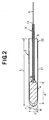
- Fig. 1 is a perspective view depicting an applicator with a sanitary tampon and Fig. 2 is a sectional view taken along line II - II in Fig. 1.
- An applicator 1 comprises an outer cylindrical tube 2 casing therein a tampon 4 and an inner plunger or piston 3 axially movable within the outer cylindrical tube 2.
- the inner plunger 3 is also in the form of tube.
- the tampon 4 is provided on its rear end with a string 6 extending rearward through the inner plunger 3 beyond a rear end of the inner plunger 3.
- the outer cylindrical tube 2 has openings 7, 8 at its front and rear ends.
- the front end opening 7 is normally covered with a plurality of elastically deformable petal-like portions 9 and the inner plunger 3 extends rearward through the outer cylindrical tube 2 beyond its rear end opening 8.
- a full length L of the outer cylindrical tube 2 is defined by an insertion region 21 intended to be inserted into the vaginal canal of the user when the tampon 4 is actually used and a grip region 22 intended to be held by the user's fingers.
- the insertion region 21 has a length corresponding to a full length A of the tampon 4 plus 40 ⁇ 60 mm and the grip region 22 has a length of 10 ⁇ 20 mm.
- the full length L may be selected within a range of approximately 70 mm ⁇ approximately 140 mm. While an outer diameter D of the outer cylindrical tube 2 may be appropriately dimensioned so far as the outer cylindrical tube 2 can be smoothly inserted into the vaginal canal, the outer diameter D is preferably dimensioned in a range of 8 ⁇ 20 mm. A wall thickness of the outer cylindrical tube 2 is substantially uniform except the petal-like portions 9.
- the outer cylindrical tube 2 configured as has been described above is made of soft and elastic thermoplastic material so that the petal-like portions 9 may be elastically deformed with the minimum resistance to fully open the front end opening 7 and more preferably the outer cylindrical tube 2 as a whole may have a sufficient flexibility to follow a curvature of the vaginal canal.
- the inner plunger 3 is a straight element having openings 16, 17 at its front and rear ends, respectively.
- the front end opening 16 intended to be placed against the rear end of the tampon 4 has its peripheral edge flared like a trumpet so that the string 6 of the tampon 4 may be easily inserted thereinto and the rear end of the tampon 4 may be pushed forward over an area as large as possible.
- the rear end opening 17 and a region in the vicinity of the opening 17 of the inner plunger 3 extend rearward beyond the rear end opening 8 of the outer cylindrical tube 2. While the inner plunger 3 also has a flexibility, the flexibility of the inner plunger 3 is preferably lower than the flexibility of the outer cylindrical tube 2 in order to ensure that the tampon 4 can be smoothly ejected.
- the tampon 4 is cased within a region of the outer cylindrical tube 2 adjacent its front end and provided with the string 6 extending rearward from the rear end of the tampon 4 through the inner plunger 3 beyond its rear end opening 17.
- the string 6 is used to draw the tampon 4 out from the vaginal canal.
- the tampon 4 functions to push open the petal-like portions 9 as the tampon 4 is pushed by the inner plunger 3 from behind until the tampon 4 completely leaves the outer cylindrical tube 2.
- Such tampon 4 has a full length A preferably in a range of 20 ⁇ 60 mm and an outer diameter B dimensioned so that its outer peripheral surface defined by the outer diameter B may be brought in close contact with an inner peripheral surface of the outer cylindrical tube 2.
- the insertion region 21 is received by the vaginal canal.
- the tampon 4 lies in front of said insertion region 21 and therefore the rear end of the tampon 4 is spaced from the vaginal opening by dimensional differences between the insertion region 21 and the tampon 4, i.e., 40 ⁇ 60 mm.
- Such tampon 4 can be stayed within the vaginal canal by pushing the inner plunger 3 into the vaginal canal with the outer cylindrical tube 2 being held or by drawing the outer cylindrical tube 2 out from the vaginal canal with the inner plunger 3 being held.
- the tampon 4 is held within the vaginal canal's innermost region spaced from the vaginal opening as far as 40 mm or more. Accordingly, it is not concerned that the tampon 4 might exert a pressure upon the sphincteral muscle and give the user a sense of incompatibility due to use of the tampon 4.
- the tampon adapted to be used in such a manner in which the outer cylindrical tube 2 is drawn out from the vaginal canal with the inner plunger 3 being held, it is no more necessary to push a firmly compression molded tampon from behind into the innermost region of the vaginal canal as the prior art has been the case.
- this invention allows a relatively soft tampon 4 to be used and such soft tampon 4 advantageously enables menstrual discharge to be rapidly absorbed.
- the sanitary tampon combined with the applicator provided by this invention enables the tampon to be reliably positioned within the innermost region of the vaginal canal without giving the user a sense of incompatibility since the applicator is longer than the tampon by 40 mm or more.
Landscapes
- Health & Medical Sciences (AREA)
- Life Sciences & Earth Sciences (AREA)
- Heart & Thoracic Surgery (AREA)
- Epidemiology (AREA)
- Engineering & Computer Science (AREA)
- Biomedical Technology (AREA)
- Vascular Medicine (AREA)
- Animal Behavior & Ethology (AREA)
- General Health & Medical Sciences (AREA)
- Public Health (AREA)
- Veterinary Medicine (AREA)
- Environmental Sciences (AREA)
- Absorbent Articles And Supports Therefor (AREA)
Abstract
Description
Claims (3)
- An applicator with a sanitary tampon, said applicator comprising an outer cylindrical tube having openings at front and rear ends thereof and an inner plunger axially movable within said outer cylindrical tube, and said tampon cased within a region of said outer cylindrical tube adjacent said front end thereof and adapted to be ejected by said inner plunger out of said opening of said front end, wherein said outer cylindrical tube has a length dimensioned to be longer than a length of said tampon by 50 ~ 80 mm.
- The applicator according to Claim 1, wherein said tampon has a length of 20 ~ 60 mm.
- The applicator according to Claim 1, wherein said inner plunger is in the form of tube, and a string provided on a rear end of said tampon extends rearward through said inner plunger beyond a rear end of said inner plunger.
Applications Claiming Priority (2)
| Application Number | Priority Date | Filing Date | Title |
|---|---|---|---|
| JP09266599A JP3913398B2 (en) | 1999-03-31 | 1999-03-31 | Sanitary tampon with applicator |
| JP9266599 | 1999-03-31 |
Publications (3)
| Publication Number | Publication Date |
|---|---|
| EP1040809A2 true EP1040809A2 (en) | 2000-10-04 |
| EP1040809A3 EP1040809A3 (en) | 2001-05-02 |
| EP1040809B1 EP1040809B1 (en) | 2005-09-28 |
Family
ID=14060784
Family Applications (1)
| Application Number | Title | Priority Date | Filing Date |
|---|---|---|---|
| EP00302682A Expired - Lifetime EP1040809B1 (en) | 1999-03-31 | 2000-03-30 | Applicator with sanitary tampon |
Country Status (11)
| Country | Link |
|---|---|
| US (1) | US6355011B2 (en) |
| EP (1) | EP1040809B1 (en) |
| JP (1) | JP3913398B2 (en) |
| KR (1) | KR100657832B1 (en) |
| CN (1) | CN1150871C (en) |
| CA (1) | CA2302100C (en) |
| DE (1) | DE60022809T2 (en) |
| ID (1) | ID25431A (en) |
| MY (1) | MY119097A (en) |
| SG (1) | SG83202A1 (en) |
| TW (1) | TW530637U (en) |
Cited By (1)
| Publication number | Priority date | Publication date | Assignee | Title |
|---|---|---|---|---|
| KR100657832B1 (en) * | 1999-03-31 | 2006-12-15 | 유니챰 가부시키가이샤 | Menstrual tampon with applicator |
Families Citing this family (9)
| Publication number | Priority date | Publication date | Assignee | Title |
|---|---|---|---|---|
| WO2004000160A2 (en) * | 2002-06-21 | 2003-12-31 | Playtex Products, Inc. | Tapered tampon applicator |
| USD572362S1 (en) | 2003-04-04 | 2008-07-01 | Playtex Products, Inc. | Tampon applicator with finger grip |
| USD492033S1 (en) | 2003-04-04 | 2004-06-22 | Playtex Products, Inc. | Tampon applicator assembly |
| US7044928B2 (en) | 2003-04-04 | 2006-05-16 | Platex Products, Inc. | Tampon applicator assembly having an improved plunger and methods of making |
| AU2004253945B2 (en) * | 2003-06-26 | 2009-02-19 | Playtex Products, Inc. | A coating composition and articles coated therewith |
| JP4249047B2 (en) | 2004-01-30 | 2009-04-02 | ユニ・チャーム株式会社 | Sanitary tampons |
| AU2005220860B2 (en) | 2004-03-08 | 2011-03-03 | Playtex Products, Inc. | Tampon applicator and method for making same |
| JP4964487B2 (en) | 2006-04-18 | 2012-06-27 | ユニ・チャーム株式会社 | Individual package and manufacturing method thereof |
| JP5320492B2 (en) * | 2012-06-22 | 2013-10-23 | ユニ・チャーム株式会社 | tampon |
Family Cites Families (14)
| Publication number | Priority date | Publication date | Assignee | Title |
|---|---|---|---|---|
| GB561173A (en) | 1941-12-23 | 1944-05-09 | Vernon Calhoun | Improvements in catamenial devices |
| US3765417A (en) | 1971-02-24 | 1973-10-16 | Kimberly Clark Co | Arcuate tampon applicator |
| US3762413A (en) * | 1972-06-21 | 1973-10-02 | Kimberly Clark Co | Tampon with multiple strings |
| US4077408A (en) | 1974-01-24 | 1978-03-07 | Murray Jerome L | Catamenial device employing polymeric constraining means |
| AU7177281A (en) | 1981-01-23 | 1982-08-16 | Kcdp Corp. | Fluid expansible contraceptive tampon and applicator |
| DE3121364A1 (en) * | 1981-05-29 | 1982-12-16 | Henkel KGaA, 4000 Düsseldorf | "APPLICATOR FOR THE HYGIENIC INSERTION OF A TAMPON" |
| EP0104039B1 (en) | 1982-09-17 | 1987-12-09 | Smith and Nephew Associated Companies p.l.c. | Tampons and applicators |
| FR2546399B1 (en) | 1983-05-24 | 1987-06-26 | Serimed Ste Civile | APPLICATOR FOR THE PLACEMENT OF AN OBJECT IN THE VAGINA OF A FEMALE ANIMAL |
| US4620534A (en) | 1984-11-01 | 1986-11-04 | New Mexico State University Foundation | Apparatus for insertion of an intravaginal article |
| AU673812B2 (en) * | 1992-01-13 | 1996-11-28 | Tambrands, Inc. | Tampon applicator |
| HK1007100A1 (en) * | 1992-11-06 | 1999-04-01 | Tambrands, Inc. | Tampon applicator |
| US5674239A (en) | 1995-02-21 | 1997-10-07 | Zadini; Filiberto P. | Intravaginal balloon for blood leakage prevention |
| US5643196A (en) * | 1995-03-03 | 1997-07-01 | Tambrands Inc. | Tampon applicator |
| JP3913398B2 (en) * | 1999-03-31 | 2007-05-09 | ユニ・チャーム株式会社 | Sanitary tampon with applicator |
-
1999
- 1999-03-31 JP JP09266599A patent/JP3913398B2/en not_active Expired - Lifetime
-
2000
- 2000-03-24 CA CA002302100A patent/CA2302100C/en not_active Expired - Lifetime
- 2000-03-28 US US09/536,408 patent/US6355011B2/en not_active Expired - Lifetime
- 2000-03-29 ID IDP20000248A patent/ID25431A/en unknown
- 2000-03-30 MY MYPI20001287A patent/MY119097A/en unknown
- 2000-03-30 EP EP00302682A patent/EP1040809B1/en not_active Expired - Lifetime
- 2000-03-30 DE DE60022809T patent/DE60022809T2/en not_active Expired - Lifetime
- 2000-03-30 KR KR1020000016420A patent/KR100657832B1/en not_active Expired - Lifetime
- 2000-03-31 TW TW089205452U patent/TW530637U/en not_active IP Right Cessation
- 2000-03-31 SG SG200001899A patent/SG83202A1/en unknown
- 2000-03-31 CN CNB001053256A patent/CN1150871C/en not_active Expired - Lifetime
Cited By (1)
| Publication number | Priority date | Publication date | Assignee | Title |
|---|---|---|---|---|
| KR100657832B1 (en) * | 1999-03-31 | 2006-12-15 | 유니챰 가부시키가이샤 | Menstrual tampon with applicator |
Also Published As
| Publication number | Publication date |
|---|---|
| KR100657832B1 (en) | 2006-12-15 |
| EP1040809B1 (en) | 2005-09-28 |
| US20010056253A1 (en) | 2001-12-27 |
| CN1268342A (en) | 2000-10-04 |
| CA2302100C (en) | 2003-10-28 |
| SG83202A1 (en) | 2001-09-18 |
| DE60022809T2 (en) | 2006-07-06 |
| DE60022809D1 (en) | 2006-02-09 |
| TW530637U (en) | 2003-05-01 |
| MY119097A (en) | 2005-03-31 |
| CA2302100A1 (en) | 2000-09-30 |
| US6355011B2 (en) | 2002-03-12 |
| KR20000063066A (en) | 2000-10-25 |
| JP3913398B2 (en) | 2007-05-09 |
| JP2000279445A (en) | 2000-10-10 |
| ID25431A (en) | 2000-10-05 |
| EP1040809A3 (en) | 2001-05-02 |
| CN1150871C (en) | 2004-05-26 |
Similar Documents
| Publication | Publication Date | Title |
|---|---|---|
| EP1040808B1 (en) | Applicator for sanitary tampon | |
| US9737443B2 (en) | Ergonomic tampon applicator | |
| US4411647A (en) | Tampon applicator | |
| CN103384508A (en) | Method for assembling a tampon applicator | |
| EP1040809B1 (en) | Applicator with sanitary tampon | |
| EP1101472A3 (en) | Applicator for tampons | |
| GB2283682A (en) | Curved tampon applicator with finger grip | |
| JPH03106365A (en) | Tampon | |
| CZ2003865A3 (en) | Incontinence pad applicator | |
| US6533748B2 (en) | Tampon applicator with rounded recess | |
| GB2033754A (en) | Sanitary tampon | |
| RU2001118037A (en) | TAMPON APPLICATOR | |
| US4329991A (en) | Tampon | |
| US20040236265A1 (en) | Device for introducing an object into a vagina | |
| EP3691588B1 (en) | Tampon applicator | |
| JP4393948B2 (en) | Sanitary tampon applicator | |
| NO318411B1 (en) | Filling device for rolling cigarettes | |
| JP4653193B2 (en) | Sanitary tampon applicator | |
| EP0904746A3 (en) | A tool for inserting a stent into a catheter | |
| JPS6214852A (en) | Tampon insert jig | |
| AU2004203360A1 (en) | Tampon applicator |
Legal Events
| Date | Code | Title | Description |
|---|---|---|---|
| PUAI | Public reference made under article 153(3) epc to a published international application that has entered the european phase |
Free format text: ORIGINAL CODE: 0009012 |
|
| AK | Designated contracting states |
Kind code of ref document: A2 Designated state(s): DE FR GB NL SE |
|
| AX | Request for extension of the european patent |
Free format text: AL;LT;LV;MK;RO;SI |
|
| PUAL | Search report despatched |
Free format text: ORIGINAL CODE: 0009013 |
|
| AK | Designated contracting states |
Kind code of ref document: A3 Designated state(s): AT BE CH CY DE DK ES FI FR GB GR IE IT LI LU MC NL PT SE |
|
| AX | Request for extension of the european patent |
Free format text: AL;LT;LV;MK;RO;SI |
|
| RIC1 | Information provided on ipc code assigned before grant |
Free format text: 7A 61F 13/32 A, 7A 61F 13/34 B, 7A 61F 13/26 B |
|
| 17P | Request for examination filed |
Effective date: 20011009 |
|
| AKX | Designation fees paid |
Free format text: DE FR GB NL SE |
|
| 17Q | First examination report despatched |
Effective date: 20020705 |
|
| RAP1 | Party data changed (applicant data changed or rights of an application transferred) |
Owner name: UNI-CHARM CORPORATION |
|
| GRAP | Despatch of communication of intention to grant a patent |
Free format text: ORIGINAL CODE: EPIDOSNIGR1 |
|
| GRAS | Grant fee paid |
Free format text: ORIGINAL CODE: EPIDOSNIGR3 |
|
| GRAA | (expected) grant |
Free format text: ORIGINAL CODE: 0009210 |
|
| AK | Designated contracting states |
Kind code of ref document: B1 Designated state(s): DE FR GB NL SE |
|
| REG | Reference to a national code |
Ref country code: GB Ref legal event code: FG4D |
|
| REG | Reference to a national code |
Ref country code: SE Ref legal event code: TRGR |
|
| REF | Corresponds to: |
Ref document number: 60022809 Country of ref document: DE Date of ref document: 20060209 Kind code of ref document: P |
|
| ET | Fr: translation filed | ||
| PLBE | No opposition filed within time limit |
Free format text: ORIGINAL CODE: 0009261 |
|
| STAA | Information on the status of an ep patent application or granted ep patent |
Free format text: STATUS: NO OPPOSITION FILED WITHIN TIME LIMIT |
|
| 26N | No opposition filed |
Effective date: 20060629 |
|
| REG | Reference to a national code |
Ref country code: FR Ref legal event code: PLFP Year of fee payment: 17 |
|
| REG | Reference to a national code |
Ref country code: FR Ref legal event code: PLFP Year of fee payment: 18 |
|
| REG | Reference to a national code |
Ref country code: FR Ref legal event code: PLFP Year of fee payment: 19 |
|
| PGFP | Annual fee paid to national office [announced via postgrant information from national office to epo] |
Ref country code: NL Payment date: 20190214 Year of fee payment: 20 |
|
| PGFP | Annual fee paid to national office [announced via postgrant information from national office to epo] |
Ref country code: GB Payment date: 20190327 Year of fee payment: 20 Ref country code: DE Payment date: 20190319 Year of fee payment: 20 |
|
| PGFP | Annual fee paid to national office [announced via postgrant information from national office to epo] |
Ref country code: FR Payment date: 20190213 Year of fee payment: 20 Ref country code: SE Payment date: 20190311 Year of fee payment: 20 |
|
| REG | Reference to a national code |
Ref country code: DE Ref legal event code: R071 Ref document number: 60022809 Country of ref document: DE |
|
| REG | Reference to a national code |
Ref country code: NL Ref legal event code: MK Effective date: 20200329 |
|
| REG | Reference to a national code |
Ref country code: GB Ref legal event code: PE20 Expiry date: 20200329 |
|
| PG25 | Lapsed in a contracting state [announced via postgrant information from national office to epo] |
Ref country code: GB Free format text: LAPSE BECAUSE OF EXPIRATION OF PROTECTION Effective date: 20200329 |
|
| REG | Reference to a national code |
Ref country code: SE Ref legal event code: EUG |