EP1040579B1 - A folding keyboard with sliding segments for electronic products - Google Patents
A folding keyboard with sliding segments for electronic products Download PDFInfo
- Publication number
- EP1040579B1 EP1040579B1 EP98964049A EP98964049A EP1040579B1 EP 1040579 B1 EP1040579 B1 EP 1040579B1 EP 98964049 A EP98964049 A EP 98964049A EP 98964049 A EP98964049 A EP 98964049A EP 1040579 B1 EP1040579 B1 EP 1040579B1
- Authority
- EP
- European Patent Office
- Prior art keywords
- wing
- keyboard
- segment
- assembly
- platform
- Prior art date
- Legal status (The legal status is an assumption and is not a legal conclusion. Google has not performed a legal analysis and makes no representation as to the accuracy of the status listed.)
- Expired - Lifetime
Links
Images


Classifications
-
- H—ELECTRICITY
- H01—ELECTRIC ELEMENTS
- H01H—ELECTRIC SWITCHES; RELAYS; SELECTORS; EMERGENCY PROTECTIVE DEVICES
- H01H13/00—Switches having rectilinearly-movable operating part or parts adapted for pushing or pulling in one direction only, e.g. push-button switch
- H01H13/70—Switches having rectilinearly-movable operating part or parts adapted for pushing or pulling in one direction only, e.g. push-button switch having a plurality of operating members associated with different sets of contacts, e.g. keyboard
- H01H13/86—Switches having rectilinearly-movable operating part or parts adapted for pushing or pulling in one direction only, e.g. push-button switch having a plurality of operating members associated with different sets of contacts, e.g. keyboard characterised by the casing, e.g. sealed casings or casings reducible in size
-
- G—PHYSICS
- G06—COMPUTING; CALCULATING OR COUNTING
- G06F—ELECTRIC DIGITAL DATA PROCESSING
- G06F1/00—Details not covered by groups G06F3/00 - G06F13/00 and G06F21/00
- G06F1/16—Constructional details or arrangements
- G06F1/1613—Constructional details or arrangements for portable computers
- G06F1/1615—Constructional details or arrangements for portable computers with several enclosures having relative motions, each enclosure supporting at least one I/O or computing function
- G06F1/1616—Constructional details or arrangements for portable computers with several enclosures having relative motions, each enclosure supporting at least one I/O or computing function with folding flat displays, e.g. laptop computers or notebooks having a clamshell configuration, with body parts pivoting to an open position around an axis parallel to the plane they define in closed position
-
- G—PHYSICS
- G06—COMPUTING; CALCULATING OR COUNTING
- G06F—ELECTRIC DIGITAL DATA PROCESSING
- G06F1/00—Details not covered by groups G06F3/00 - G06F13/00 and G06F21/00
- G06F1/16—Constructional details or arrangements
- G06F1/1613—Constructional details or arrangements for portable computers
- G06F1/1615—Constructional details or arrangements for portable computers with several enclosures having relative motions, each enclosure supporting at least one I/O or computing function
- G06F1/1624—Constructional details or arrangements for portable computers with several enclosures having relative motions, each enclosure supporting at least one I/O or computing function with sliding enclosures, e.g. sliding keyboard or display
-
- G—PHYSICS
- G06—COMPUTING; CALCULATING OR COUNTING
- G06F—ELECTRIC DIGITAL DATA PROCESSING
- G06F1/00—Details not covered by groups G06F3/00 - G06F13/00 and G06F21/00
- G06F1/16—Constructional details or arrangements
- G06F1/1613—Constructional details or arrangements for portable computers
- G06F1/1633—Constructional details or arrangements of portable computers not specific to the type of enclosures covered by groups G06F1/1615 - G06F1/1626
- G06F1/1656—Details related to functional adaptations of the enclosure, e.g. to provide protection against EMI, shock, water, or to host detachable peripherals like a mouse or removable expansions units like PCMCIA cards, or to provide access to internal components for maintenance or to removable storage supports like CDs or DVDs, or to mechanically mount accessories
-
- G—PHYSICS
- G06—COMPUTING; CALCULATING OR COUNTING
- G06F—ELECTRIC DIGITAL DATA PROCESSING
- G06F1/00—Details not covered by groups G06F3/00 - G06F13/00 and G06F21/00
- G06F1/16—Constructional details or arrangements
- G06F1/1613—Constructional details or arrangements for portable computers
- G06F1/1633—Constructional details or arrangements of portable computers not specific to the type of enclosures covered by groups G06F1/1615 - G06F1/1626
- G06F1/1662—Details related to the integrated keyboard
- G06F1/1666—Arrangements for reducing the size of the integrated keyboard for transport, e.g. foldable keyboards, keyboards with collapsible keys
-
- G—PHYSICS
- G06—COMPUTING; CALCULATING OR COUNTING
- G06F—ELECTRIC DIGITAL DATA PROCESSING
- G06F1/00—Details not covered by groups G06F3/00 - G06F13/00 and G06F21/00
- G06F1/16—Constructional details or arrangements
- G06F1/1613—Constructional details or arrangements for portable computers
- G06F1/1633—Constructional details or arrangements of portable computers not specific to the type of enclosures covered by groups G06F1/1615 - G06F1/1626
- G06F1/1662—Details related to the integrated keyboard
- G06F1/1671—Special purpose buttons or auxiliary keyboards, e.g. retractable mini keypads, keypads or buttons that remain accessible at closed laptop
-
- G—PHYSICS
- G06—COMPUTING; CALCULATING OR COUNTING
- G06F—ELECTRIC DIGITAL DATA PROCESSING
- G06F1/00—Details not covered by groups G06F3/00 - G06F13/00 and G06F21/00
- G06F1/16—Constructional details or arrangements
- G06F1/1613—Constructional details or arrangements for portable computers
- G06F1/1633—Constructional details or arrangements of portable computers not specific to the type of enclosures covered by groups G06F1/1615 - G06F1/1626
- G06F1/1684—Constructional details or arrangements related to integrated I/O peripherals not covered by groups G06F1/1635 - G06F1/1675
- G06F1/169—Constructional details or arrangements related to integrated I/O peripherals not covered by groups G06F1/1635 - G06F1/1675 the I/O peripheral being an integrated pointing device, e.g. trackball in the palm rest area, mini-joystick integrated between keyboard keys, touch pads or touch stripes
-
- G—PHYSICS
- G06—COMPUTING; CALCULATING OR COUNTING
- G06F—ELECTRIC DIGITAL DATA PROCESSING
- G06F3/00—Input arrangements for transferring data to be processed into a form capable of being handled by the computer; Output arrangements for transferring data from processing unit to output unit, e.g. interface arrangements
- G06F3/01—Input arrangements or combined input and output arrangements for interaction between user and computer
- G06F3/02—Input arrangements using manually operated switches, e.g. using keyboards or dials
- G06F3/0202—Constructional details or processes of manufacture of the input device
- G06F3/0221—Arrangements for reducing keyboard size for transport or storage, e.g. foldable keyboards, keyboards with collapsible keys
-
- H—ELECTRICITY
- H01—ELECTRIC ELEMENTS
- H01H—ELECTRIC SWITCHES; RELAYS; SELECTORS; EMERGENCY PROTECTIVE DEVICES
- H01H2223/00—Casings
- H01H2223/046—Casings convertible
- H01H2223/05—Casings convertible composed of hingedly connected sections
Abstract
Description
- This invention relates generally to a keyboard and, more particularly, to a keyboard with one or more assemblies which slide and fold with respect to each other to minimize the overall size of the keyboard.
- Keyboards are used in a variety of different portable and stationary applications, such as palmtop or hand-held computers, notebook computers, sub-notebook computers, digital organizers or personal digital assistants (PDAs), digital cameras with annotation or editing capability, data-capable mobile phones, video consumer game electronics, entertainment electronics, calculators, stationary telephones, and small form-factor stationary (desktop) computers, to enter text, numerical, and/or control information. In many of these portable and stationary applications, it is desirable for the overall size of the keyboards to be reduced when the keyboards and products are stored and transported, especially for portable applications. However, during use, it is desirable for the keyboards to conform to standard sizes to have a typical "feel" for ease and comfort of use. The overall size of the keyboard is particularly critical for text entry via "touch typing." As discussed below, a variety of different types of keyboards have been developed to meet these contradictory requirements with varying degrees of success.
- One solution to achieve both small overall size during storage and transport and standard size during use is the "fixed segment", i.e. no sliding segments, folding keyboard design. Characteristic of these designs is that the keyboard is divided into segments which fold, but do not slide and with the keys maintaining a fixed position on the segment. They are then hinged in a manner that permits the keys to properly align when the keyboard is in the open position. Examples of this design are set forth in
U.S. Patent No. 3, 940,758 to Margolin , -
U.S. Patent No. 5,187,644 to Crisan ,U.S. Patent No. 5,278,779 to Conway et al ,U.S. Patent No. 5,457,453 to Chiu et al ,U.S. Patent No. 5,519,569 to Sellers ,U.S. Design Patent No. 254,554 to Genaro et al ,U.S. Design Patent No. 299,030 to Menn ,U.S. Design Patent No. 322,246 to Izaki andU.S. Design Patent No. 324,035 to Izaki . - Similarly
WO 95/10106 US 5687058 discloses an expandable keyboard. A first assembly may be held face to face or side by side of a central segment of the keyboard by virtue of a triple hinge arrangement which connects the two assemblies via three pivotal connections. - One of the problems with this prior design is with the electrical interconnections between the central segment and the folding segment which arise from two issues. First, because the layout of a standard typing keyboard offsets the rows of keys, the ends of the keyboard segments present a "stepped" pattern. This complicates and limits the available methods of electrical interconnection between the segments and makes it very difficult to provide Electro Static Discharge (ESD) protection at the points of interconnection when the keyboard is in the folded state. The "stepped" pattern when the keyboard is in the folded state presents mechanical problems with providing a mechanically and aesthetically suitable protective cover, often dictating a complicated cover with multiple hinged segments to protect the exposed edges from ESD, environmental and impact damage. Second, the pivoting nature of the folding segment with respect to the central segment brings the one set of the interconnecting mating electrical connectors in towards the other set of connectors at an arc, rather than straight on, which imposes limitations on the interconnection methods. Typically, the electrical interconnection is made either by a flexible ribbon type connector or by interconnecting mating electrical connectors along the side of each segment which are joined together. Unfortunately, the flexible ribbon type connectors are subject to fatigue over time from the bending and can fray and break. Due to the arc-shaped path followed by the opening keyboard segment when opened, it is impossible to use an interconnection method that relies on mating connecting members approaching along a straight-line path, or upon continuous, uniform compression from the top to the bottom of the connecting region.
- Another problem with this design is that when the folding segments are folded out from the central segment they are not securely held in place. As a result, the resulting expanded or full size keyboard is flimsy unless an additional locking mechanism is provided.
- Another design to achieve both small overall size during storage and transport and standard size during use is disclosed in
U.S. Patent No. 5,267,127 to Pollitt . In this design, the keyboard assembly is split in half and each half of the keyboard assembly can be slid along a keyboard axis between a split position and a connected position. The halves of the keyboard assembly are not folded with respect to each other. -
US 5659307 discloses an expandable keyboard which exists in its collapsed state when the box housing it is closed. As the lid of the box is opened, a mechanism actuates the expansion of the keyboard automatically. -
US 5574481 discloses a detachable expandable keyboard in which keyboard units slide over a hinged base frame. - One of the problems with this design is that the width or depth of the electronic product on which the halves of the keyboard assembly ride on and are stored on is still fairly large. It is a property of this design that the degree of expansion in the overall length of the keyboard is in proportion to the depth of the unit. As a result, overall size is not significantly reduced. Additionally, because the size is not significantly reduced, this design is not desirable for some smaller applications, such as handheld computers or mobile telephones.
- "MEHR ALS EIN TASTATUR" Gunter M et Al discloses a keyboard which has a means of receiving and reading memory cards.
- An expandable keyboard in accordance with the present invention includes a central keyboard assembly and a first assembly comprising a first segment and a first wing. The central keyboard assembly includes one or more keys and a platform. The first wing is pivotally connected along one side to one side of the platform about a first axis and is pivotable to a closed position where the first wing rests substantially on the platform and to an open position where the first wing provides an extension of the platform. The first segment is slidably connected to the first wing and is movable to a first position which exposes the first axis and permits the first wing to pivot about the first axis, and to a second position which covers the first axis and substantially prevents the first wing from pivoting about the first axis. The expandable keyboard may also include a second assembly comprising a second segment and a second wing. The second wing is pivotally connected along one side to one side of the platform about a second axis and is pivotable to a closed position where the second wing rests substantially on the platform and to an open position where the second wing provides an extension of the platform. The second segment is slidably connected to the second wing and is moveable to a first position which exposes the second axis and permits the second wing to pivot about the second axis and to a second position which covers the second axis and substantially prevents the second wing from pivoting about the second axis.
- An expandable keyboard in accordance with the present invention provides several advantages. For example, the expandable keyboard can easily be made small and compact for storage and can easily be converted to up to substantially twice its folded length for use. Additionally, the sliding segment is designed to provide a large number of inexpensive and optimized interconnections between the central assembly and the first and second assemblies because the first and second assemblies are brought into electrical contact with the central assembly along a straight line, rather than in an arc. A large number of interconnections capable of transporting both power and low-level signals is highly desirable due to the ability to locate circuitry or removable modules like PCMCIA cards in the wing sections. Further, when the first and second wings are folded to an open position and the first and second segments are slid into the second position they provide a sturdy and durable standard size keyboard. The duplication of the electrical connections between the edge of the keyboard segments and the top surfaces of the central keyboard and the movable segments permits operation of any circuitry or removable PCMCIA or Smart cards, keypads, speakers, microphones etc. contained in the wings when the wings are in the closed position. The invention also provides automatically operated ESD protection for all electrical contacts during both storage and operation with the keyboard open or closed.
-
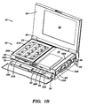
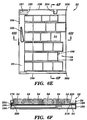
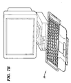
- FIG. 1A is a front perspective view of one embodiment of the expandable keyboard in accordance with the present invention in a portable computer in a fully closed position;
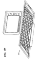
- FIG. 1B is a front perspective view of the expandable keyboard in the portable computer in a partially open position;
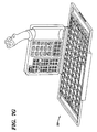
- FIG. 1C is a front perspective view of the expandable keyboard in a fully open position with the keyboard-bases in the first position;
- FIG. 1D is a front perspective view of the expandable keyboard in the portable computer in a fully open position with the keyboard-bases in the second position;
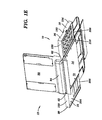
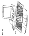
- FIG. 1E is a back perspective view of the expandable keyboard in the portable computer in a fully open position;
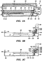
- FIG. 2A is a cross-sectional view of the expandable keyboard in the portable computer in a fully closed position taken along
lines 2A-2A in FIG. 1A, with the wing keyboard segment omitted for clarity; - FIG. 2B is a cross-sectional view of the expandable keyboard in the portable computer shown in FIG. 2A with a the central keyboard assembly, the hinged wing sections and portions of the portable computer removed;
- FIG. 2C is another cross-sectional view of the expandable keyboard shown in FIG. 2A in the portable computer with the central keyboard assembly, the hinged wing sections and portions of the portable computer removed;
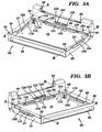
- FIG. 3A is a perspective view from one side of the platform for the central keyboard assembly;
- FIG. 3B is a perspective view from another side of the platform for the central keyboard assembly;
- FIG. 3C is a perspective view from the back of the platform for the central keyboard assembly;
- FIG. 3D is a block diagram of the keyboard interconnect, interconnect for devices installable in the keyboard wing sections, and of the circuitry for the computer;
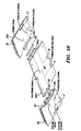
- FIG. 3E is an exploded view of a portion of the central housing and right and left keyboard assemblies showing the components in the electrical interconnect between the wings and the central section;
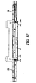
- FIG. 3F is a cross-sectional view of a portion of the central, right, left keyboard assemblies showing the elements that comprise the electrical interconnect when the keyboard is in the open position (although the keyboard is in the open position, for purposes of illustration only, the top-surface interconnect on the right-hand side is shown in the closed position);
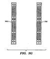
- FIG. 3G is a front view of one example of the pairs of identical PC connector boards used in electrically connecting the wing to the central keyboard assembly;
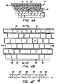
- FIG. 4A is a perspective top view of a portion of the central keyboard assembly;
- FIG. 4B is a top view of a portion of the central keyboard assembly;
- FIG. 4C is a cross-sectional view of a portions of the central keyboard assembly taken along
line 4C-4C in FIG. 4B; - FIG. 5A is a top perspective view of the right keyboard assembly;
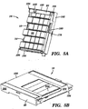
- FIG. 5B is a bottom perspective view of the right keyboard assembly;
- FIG. 5C is a top view of the keyboard-base for the right keyboard assembly with a plurality of keys;
- FIG. 5D is a bottom perspective view of the right keyboard assembly with a bottom cover removed;
- FIG. 5E is a top view of the right keyboard assembly;
- FIG. 5F is a cross-sectional view of the right keyboard assembly taken along
line 5F-5F in FIG. 5E; - FIG. 5G is a partial bottom view of the keyboard-base and the actuating device for right keyboard assembly in the second position;
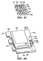
- FIG. 5H is a cross-sectional view of the right keyboard assembly taken along
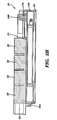
line 5H-5H in FIG. 5E; - FIG. 6A is a top perspective view of the left keyboard assembly;
- FIG. 6B is a bottom perspective view of the left keyboard assembly;
- FIG. 6C is a top view of the keyboard-base for the left keyboard assembly with a plurality of keys;
- FIG. 6D is a bottom perspective view of the left keyboard assembly with a bottom cover removed;
- FIG. 6E is a top view of the left keyboard assembly;
- FIG. 6F is a cross-sectional view of the left keyboard assembly taken along
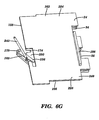
line 6F-6F in FIG. 6E; - FIG. 6G is a partial bottom view of the keyboard-base and actuating device for the left keyboard; and
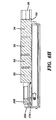
- FIG. 6H is a cross-sectional view of the left keyboard assembly taken along
line 6H-6H in FIG. 6E; - FIG. 7A is a front perspective view of another embodiment of the expandable keyboard in accordance with the present invention in a sub-notebook computer;
- FIG. 7B is a front perspective view of another embodiment of the expandable keyboard in accordance with the present invention in a small desktop computer;
- FIG. 7C is a front perspective view of another embodiment of the expandable keyboard in accordance with the present invention in a palmtop computer or similar digital organizer;
- FIG. 7D is front perspective view of another embodiment of the expandable keyboard in accordance with the present invention in a personal digital assistant;
- FIG. 7E is a front perspective view of another embodiment of the expandable keyboard in accordance with the present invention in a stationary telephone;
- FIG. 7F is a front perspective view of another embodiment of the expandable keyboard in accordance with the present invention in a mobile telephone; and
- FIG. 7G is a front perspective view of another embodiment of the expandable keyboard in accordance with the present invention with a remote control and a joystick.
- One embodiment of an
expandable keyboard 10 in accordance with the present invention in aportable computer 12 is illustrated in FIGS. 1A-1E. Theexpandable keyboard 10 includes acentral keyboard assembly 14, aright keyboard assembly 16 comprising afirst segment 18 and afirst wing 20, and aleft keyboard assembly 22 comprising asecond segment 24 and asecond wing 26. Theexpandable keyboard 10 provides a number of advantages including providing a keyboard that can easily be made small and compact for storage and standard size for use. Additionally, theexpandable keyboard 10 provides a large number of optimized and reliable electrical interconnects, serving the keyboard segments and additional circuitry or removable modules; such as PCMCIA cards, incorporated into the right and left keyboard assemblies, between thecentral assembly 14 and right and leftkeyboard assemblies - Referring more specifically to FIGS. 1C, 1D, 2A, 3D, and 4A-4C, the
central keyboard assembly 14 includeskeys 28 and a keyboard-base 30. Each of thekeys 28 is substantially the same size as keys found on a standard keyboard. It is readily apparent that other embodiments of this expandable keyboard may have larger size keyboards or smaller size keyboards for pocket size devices. Thekeys 28 on thecentral keyboard assembly 14 only comprise a portion of the keys normally found on a standard size keyboard. The remainingkeys keyboard assemblies base 30 by a biasing device containing an electrical switch. (not shown) connected between the keyboard-base 30 and each key 28. Each of the key tops is normally held in substantially the same plane. When a key 28 is depressed, the key 28 completes a connection which is typically coupled to circuitry in the electrical product, in this example theportable computer 12. Such a coupling may be entirely internal within the electronic device, or may involve a cable or wireless means depending on the environment where the keyboard is deployed. Depending on the requirements of a particular application, tradeoffs are often made between the "touch typing quality" of a keyboard and the acceptable thickness of the keyboard. Although one type ofkey 28 is illustrated and described, other types of keys, such as dome switches or membrane keys, with or without rigid keycaps, can also be used alone or in combination as needed or desired. - In this particular embodiment, the
keys main circuit board 37. Additionally, each of the components contained within the right, and leftkeyboard assemblies central keyboard assembly 14 which is coupled to main circuit board orcircuitry 37 for the electronic product, is shown in FIG. 3D. The main circuit board of the personal computer for this particular embodiment includes a variety of components, such as a CPU, RAM, ROM, display, and an I/O device, although thecircuitry 37 could have other components as needed or desired. By way of example only,U.S. Patent No. 5,267,127 to Pollitt , discloses circuitry for a portable computer and its operation in greater detail. Although in this particular embodiment, the central, right, and leftkeyboard assemblies computer 12, the central, right, and leftkeyboard assemblies keyboard 10 which is coupled to an input/output device on thecomputer 12 coupled tocircuitry 37. This would be the case if the keyboard were located in a separate housing from the computer, and thus coupled by a cable or by Infra-Red, RF or other wired or wireless means. - The keyboard-
base 30 for thecentral keyboard assembly 14 includes opposing side edges 46 and 48, afront edge 50, and aback edge 52. Due to the fact that in this particular embodiment, a standard size keyboard is broken into sections which are found in the central, right, and leftkeyboard assemblies central keyboard assembly 14 and theright keyboard assembly 16 and the side edges 48 and 56 at the break between thecentral keyboard assembly 14 and theleft keyboard assembly 22 are not straight and are patterned around the arrangement of the break betweenkeys keys right keyboard assemblies 14 and 16 (two segments), the central and leftkeyboard assemblies 14 and 22 (two segments), or could all be located on just on thecentral keyboard assembly 14 with other electronic components, such as microphones, telephone key pads, or slot for electronic cards such as PCMCIA or smart cards, located on the right and/or theleft keyboard assemblies 16 and 22 (one keyboard segment plus outboard segments for I/O). The front and back edges 50 and 52 of the keyboard-base 30 for thecentral keyboard assembly 14 each include alip keys 28. - Referring to FIGS. 1C, 1D, 1E, 2A-2C, and 3A-3C, the
central keyboard assembly 14 also includes aplatform 62 which in this particular embodiment has aback wall 64, afront wall 66, opposingside walls floor 72 connected together to form a substantially rectangular shaped-structure. Additionally, in this particular embodiment the main circuit board orcircuitry 37 for the portable computer is located on thefloor 72 of theplatform 62 for thecentral keyboard assembly 14, although all or part of it could be located elsewhere as needed or desired. When the expandable keyboard is used in other portable or stationary applications, theexpandable keyboard 10 may simply be coupled via a connector, a cable, or other wired or wireless means to the location where circuitry for the particular application is contained. - Referring to FIGS. 2A-2C, a
channel 74 is formed on the inner surface of theback wall 64 and anotherchannel 76 is formed on the inner surface of thefront wall 66. Thelip 60 adjacent theback edge 52 of the keyboard-base 30 for thecentral keyboard assembly 14 is seated in thechannel 74 and thelip 58 adjacent thefront edge 50 of the keyboard-base 30 or thecentral keyboard assembly 14 is seated in thechannel 76. Although not shown, the keyboard-base 30 for thecentral keyboard assembly 14 may also be secured to the inner surface of theside walls - Referring to FIGS. 1C, 1D, and 3A-3C, one
part 78 of a pivotal connection is located adjacent one of the top corners of thefront wall 66 and onepart 80 of another pivotal connection is located adjacent the other top corner of thefront wall 66. Each of theseparts front wall 66 and has an opening to receive a pivot pin. Atop strip 82 is seated between the opposingside walls back wall 64. Thetop strip 82 also has onepart 84 of a pivotal connection located adjacent one top corner of one of the opposing side walls and has onepart 86 of another pivotal connection located adjacent one top corner of the other one of the opposingside walls part top strip 82 and has an opening to receive a pivot pin. The openings inparts parts - Referring to FIGS. 1B-1E, 2A-2C and 3C-3D, the
back wall 64 has ahinge structure 88 for pivotally connecting acover 90 of theportable computer 12 to theback wall 64 of theplatform 62. Thecover 90 houses adisplay 92 which is coupled to thecircuitry 37 for theportable computer 12 on thefloor 72 of theplatform 62. Theback wall 64 may also have adetachable housing 94 for holding a battery for thecircuitry 37,display 92 and other components for theportable computer 12. - Referring to FIGS. 3A-3G a
lip 95 for aconductive elastomer 96 is adjacent to the top of one of the opposingside walls 68 and anotherlip 97 for anotherconductive elastomer 98 is adjacent to the top of the other one of the opposingside walls 70. Perpendicular PC board connectors orstrips circuitry 37.Conductive elastomer 96 is seated onlip 95 and is electrically coupled toPC board connector 96A when under compression andconductive elastomer 98 is located onlip 97 and is electrically coupled toPC board connector 98A when under compression. As illustrated in FIG. 3G,PC board connector 96A andPC board connector 104 have a plurality of contacts, which may be allocated among the functions of connecting keyboard keys, connecting other components, and supplying power and ground.Segment 18 has aPC board connector 104 and when slid into contact withconductive elastomer 96 at the second position provides the interconnect betweenPC board connectors wing 20. Note that any matching pattern of contacts, tailored for the current, shielding and other requirements of each signal is possible, constrained only by the contact spacing constraints imposed by the fiber-spacing in the conductive elastomer. Similarly, thePC board connector 106 is mated withPC board connector 98A whensegment 24 is slid into contact withsecond elastomer 98 at the second position. Each of the opposingside walls opening conductive elastomers PC board connectors conductive elastomers PC board connectors keyboard assemblies segments keyboard assemblies conductive elastomers - Additionally, the electrical coupling surfaces or electrical contacts could be incorporated into the edges of the keyboard bases 18 and 24, such that they mate with the edges of the
central keyboard base 30. Such an approach would minimize the thickness of the keyboard in an application where PCMCIA slots or additional circuitry were not incorporated into the wing sections, making it desirable to eliminate the additional thickness incurred by placing connectors under the keyboard bases. Any of the previously described interconnect methods would be applicable, including spring contacts, pin and socket connectors or conductive elastomer, as well as non-contact methods described earlier. This approach could also be used in conjunction with PCMCIA slots or circuitry in the wing sections. In this particular embodiment, these connections would couple thekeys keyboard assemblies central keyboard assembly 14. - The
expandable keyboard 10 may also includeshutters elongated shutter 108 is pivotally connected along the inner surface of one of theside walls 68 and anotherelongated shutter 110 is pivotally connected along the inner surface of the other of theside wall 70. Theelongated shutters elongated shutters conductive elastomers openings side walls spring floor 72 of theplatform 62 and anextension elongated shutters left shutter 110 in the keyboard-open position, and theright shutter 108 in the keyboard-closed position. - A
lever 120 is pivotally connected to the inner surface of theback wall 64, adjacent one of side of theback wall 64, and below thetop strip 82 with one end of thelever 120 resting on top of theextension 116 of one of theelongated shutters 108 over thespring 112. Anotherlever 122 is pivotally connected to the inner surface of theback wall 64, adjacent the other side of theback wall 64, and below thetop strip 82 with one end of thelever 122 resting on top of theextension 116 of the otherelongated shutter 110 over thespring 112. Thetop strip 82 has a pair ofopenings keyboard assemblies projections levers - Referring to FIGS. 1C, 1D, 2A-2C and 3A-3C, the other ends of each
lever shorter extension structure back wall 64 of theplatform 62. The base of each of the J-shapedstructures back wall 64 of theplatform 62. The back surface of each of thelonger extensions structures shutter shutter back wall 64 of theplatform 62. Each flat, J-shapedshutter flat biasing projection back wall 64 and to the flat, J-shapedshutter top strip 82 includes another set ofopenings top strip 82. - Elastomeric electrical connectors and their corresponding
flexible ribbon cables lever openings electrical connectors circuitry 37 via the flexible ribbon cable. The other end of eachlever electrical connectors openings connectors keyboard assemblies keyboard assembly central keyboard assembly 14. The other end of eachlever electrical connectors openings connectors keyboard assembly shutters position covering openings springs - Referring to FIGS. 3D, 5C, 5E, 6C, and 6E,
first wing 20 includes awindow 191 andsecond wing 26 includes awindow 193. Anelectrical connector 195 is located onsegment 18 and anelectrical connector 197 is located onsegment 24.Electrical connectors PC board connectors segment 18 is slid to a second position to connect theright keyboard assembly 16 with thecentral keyboard assembly 14, theconnector 195 is slid out of thewindow 191. In this position, theconnector 195 is protected from environmental and ESD damage when the keyboard is in the open and operating position. When thesegment 18 is slid back away from the central keyboard assembly, theconnector 195 is positioned inwindow 191. Whenwing 20 is folded over on to the central keyboard assembly,electrical connector 195 is coupled toelectrical connector 152. Similarly, whensegment 24 is moved towardscentral keyboard assembly 14,connector 197 is moved out ofwindow 193. Whensegment 24 is moved away fromcentral keyboard assembly 14,connector 197 is positioned inwindow 193. Whenwing 26 is folded in oncentral keyboard assembly 14,electrical connector 197 is coupled toelectrical connector 154. - The other end of each flat, J-shaped
shutter projections openings shutters openings keyboard assemblies central keyboard assembly 14 and to a position exposing theopenings keyboard assemblies central keyboard assembly 14. Again, although one type of shutter and assembly is illustrated, other types of shutters and assemblies can be used as needed or desired. - Referring to 1B-1E, 3D, 5A-5H, and 6A-6H the right and left
keyboard assemblies right keyboard assembly 16 includes thefirst segment 18 and thefirst wing 20 and theleft keyboard assembly 22 includes thesecond segment 24 and thesecond wing 26.Segment 18 is a keyboard base and includes opposing side edges 54 and 156,front edge 160, backedge 164, andtop surface 168.Segment 24 is another keyboard-base and includes opposing side edges 56 and 158,front edge 162, backedge 166, andtop surface 170. In this particular embodiment, a plurality ofkeys 32 are connected to thetop surface 168 ofsegment 18 and a plurality ofkeys 34 are connected to thetop surface 178 ofsegment 24. Thesekeys segment - One
side edge 54 of thesegment 18 for theright keyboard assembly 16 is designed to mate with oneside edge 46 of the keyboard-base 30 in thecentral keyboard assembly 14. Similarly, oneside edge 56 of thesegment 24 for theleft keyboard assembly 22 is designed to mate with oneside edge 48 of the keyboard-base 30 in thecentral keyboard assembly 14. Theother side edge 156 of thesegment 18 for theright keyboard assembly 16 has aslot 172 which fits around ashaft 176 of alever 180 used in this particular embodiment to move thesegment 18 to the first position, second position, and other positions. Similarly, theother side edge 158 of thesegment 24 for theleft keyboard assembly 22 has aslot 174 which fits around ashaft 178 of alever 182 used in this particular embodiment to movesegment 24 to the first position, second position, and other positions. - Each key 32 or 34 on the right or
left keyboard assemblies segment base PC board connector - The
wing 20 of theright keyboard assembly 16 has afront wall 184,back wall 188 andside wall 192 that are connected together to form a substantially U-shaped structure in this particular embodiment. Similarly,wing 26 of theleft keyboard assembly 22 has afront wall 186,back wall 190, andside wall 194 that are connected together to form a substantially U-shaped structure in this particular embodiment. Part 196 of a pivotal connection is located adjacent one top corner of thefront wall 184 opposite from the side wall and anotherpart 198 of a pivotal connection is located adjacent one top corner of theback wall 188 opposite from theside wall 192. Each of theseparts front wall 184 and the top corner of theback wall 188 and has an opening to receive a pivot pin. The openings in theparts parts right keyboard assembly 16 to thecentral keyboard assembly 14 to pivot about the axis B-B Similarly, the openings in theparts parts left keyboard assembly 22 to thecentral keyboard assembly 14 to pivot about the axis A-A. Again, although one type of pivotal connection is disclosed, other types of pivoting structures can also be used as needed or desired. - The
wing 20 for theright keyboard assembly 16 includes aprojection 252 onback wall 188 which is designed to fit in opening 124 intop strip 82 to engage one end oflever 120 whenright keyboard assembly 16 is in a closed position. Thewing 26 for theleft keyboard assembly 22 includes aprojection 254 onback wall 190 which is designed to fit in opening 126 intop strip 82 to engage one end oflever 122 when leftkeyboard assembly 22 is in a closed position. - The
wings keyboard assemblies bottom structure right keyboard assembly 16 are coupled toPC board connector 104 and theelectrical connector 195 and the components on the left keyboard assembly are coupled toPC board connector 106 and toelectrical connector 197. In this particular embodiment, thebottom structure 204 of thewing 20 for theright keyboard assembly 16 has aslot 208 for electronic cards, and thebottom structure 206 for the left keyboard assembly has akeypad 210 of numbers for a telephone and anothercard slot 212. When thewings keyboard assemblies central keyboard assembly 14, theslots keypad 210 of numbers for a telephone are coupled tocircuitry 37 in the electronic product viaconnectors wings keyboard assemblies slots keypad 210 of numbers for a telephone are connected viaPC boards conductive elastomers - A
track front wall 184 of thewing 20 for the righthand keyboard assembly 16 and atrack 220 is formed along the inner surface of thefront wall 186 of thewing 26 for theleft keyboard assembly 22. Anothertrack back wall 188 of thewing 20 for theright keyboard assembly 16, and atrack 216 is formed along the inner surface of theback wall 190 of thewing 26 theleft keyboard assembly 22. Thelip 222 which extends out past the front row of keys onsegment 18 for theright keyboard assembly 16 which is seated intrack 218 in the front wall, and thelip 224 which extends out past the front edge of the front row of keys on thesegment 24 for theleft keyboard assembly 22 is seated in thetrack 220 in the front wall. Thelip 226 which extends out past the back row of keys on thesegment 18 for theright keyboard assembly 16 is seated intrack 214 and thelip 228 which extends out past the back row of keys on thesegment 24 for theleft keyboard assembly 22 is seated intrack 216. - Each
segment tracks wing platform 62 about axis A-A and axis B-B, and disconnecting thePC boards conductive elastomers PC boards segment wing platform 62 about axis A-A and axis B-B, and electrically coupling thePC board connectors conductive elastomers PC board connectors PC board connectors conductive elastomers segments wings segments keyboard assemblies segments - Referring to FIGS. 1C, 1D, 5D, 5E, 5G, 5H, 6D, 6E, 6G and 6H, actuating assemblies for moving the
segments keyboard assembly U-shaped lever central shaft arm spring spring 240 for theright keyboard assembly 16 is connected to thearm 234 for thelever 180 for theright keyboard assembly 16 and the other end of thespring 240 is connected to thewing housing 20 for theright keyboard assembly 16 in the position shown. One end of thespring 242 for theleft keyboard assembly 22 is connected to thearm 236 for thelever 182 for theleft keyboard assembly 22 and the other end of thespring 242 is connected to thewing housing 26 for theleft keyboard assembly 22 in the position shown. Thecentral shaft 176 for theright keyboard assembly 16 is pivotally connected to theside wall 192 forwing 20 for theright keyboard assembly 16 and thecentral shaft 178 for theleft keyboard assembly 22 is pivotally connected to theside wall 194 forwing 26 for theleft keyboard assembly 22. In operation, thesprings levers - The
bottom surface 244 of thesegment 18 for theright keyboard assembly 16 also includes a notchedarea 248 which contains a track in which a protrusion on thesecond arm 234 for theright keyboard assembly 16 rides. Thebottom surface 246 of the keyboard-base 24 for theleft keyboard assembly 22 also includes a notchedarea 250 which contains a track in which a protrusion on thesecond arm 236 for theleft keyboard assembly 22 rides. Although one type of manual actuating assembly, is illustrated, other types of manual or automatic actuating assemblies could be used as needed or desired. One example of another means of actuation includes a spring loaded mechanism which tends to pull thesegments segments segments - Although in this particular embodiment, the
expandable keyboard 10 is illustrated with acentral keyboard assembly 14, aright keyboard assembly 16, and aleft keyboard assembly 22, other arrangements of sliding and folding sections for theexpandable keyboard 10 are within the scope of this invention. For example,expandable keyboard 10 may only have acentral keyboard assembly 14 and either aright keyboard assembly 16 or aleft keyboard assembly 22 or theexpandable keyboard 10 may have acentral keyboard assembly 14 and either or both a forward keyboard assembly and a backward keyboard assembly which would be analogous to the right and leftkeyboard assemblies expandable keyboard 10 is illustrated with aportable computer 12, theexpandable keyboard 10 can be used with a variety of different portable and stationary applications, such as palmtop computers, notebook and sub-notebook computers, digital organizers, digital cameras, mobile phones, camcorders, video consumer game electronics, video cassette recorders, calculators, and stationary telephones, and, in general, any application desiring to minimize the storage volume and area of a keyboard which can benefit from deploying the largest practical keyboard size to facilitate typing. In this embodiment, a standard size keyboard is deployed. However, pocket-size and other small products may deploy the same concepts to realize a keyboard with a smaller unfolded size. - Referring to FIGS. 1A and 1B, hinged
side cover 245 can be rotated to a first position by pivoting it abouthinge 260. To do this, the operator graspsprotrusion 262. In this first position it is stored inrecess 264 with clearance provided bynotch 249. Cover 245 can also be rotated to a second position, covering theside walls 68 of theplatform 62 andside edge 54 offirst wing 20 for transport or storage. Cover 245 is retained in the first and second positions by a detent (not shown) or by friction from the hinge. Likewise the left side cover 268 is operated in an identical manner, usingcorresponding recess 247,notch 251 and hinge 253. Although in this particular embodiment, a side cover hinged at the top is shown, other designs which take advantage of the flat surface presented byside edge 54 andside wall 68 are possible. - The operation of this particular embodiment of the
expandable keyboard 10 in aportable computer 12 is discussed below. During storage and transport, thecover 90 for theportable computer 12 is pivoted down to rest on the right and leftkeyboard assemblies cover 90 in place. Also, side covers 245 and 266 are pivoted down to cover the sides. When the side covers 245 and 266 are pivoted to the first position, cover 90 can be pivoted open, as shown in FIG. 1B. This affords the user has access to the electronic components on thebottom structures wings keyboard assemblies - In the closed position, the
keys central keyboard assembly 14,right keyboard assembly 16, and leftkeyboard assembly 22 are disconnected and may be depressed to further minimize the overall size of theexpandable keyboard 10 during storage. Another latching mechanism (not shown) may be used to hold the right and leftkeyboard assemblies cover 90 open, but with the keyboard in the folded position of FIG 1B, devices located in the movable wing sections are still electrically connected into the computermain board 37 as previously described viaelectrical connectors - With the
cover 90 open, the right and leftkeyboard assemblies wings keyboard assemblies segments keyboard assemblies central keyboard assembly 14 as shown in FIG. 1B and an open position as shown in FIGS. 1C-1E. Note that a latching mechanism (not shown) may retain thewings - Additionally, in the closed position the
projections 252 and 254 (shown in FIGS. 5A, 5E, 6A, and 6E) on theback walls wings keyboard assemblies levers openings top strip 82 and push these ends down. When these ends of eachlever projections elongated shutters springs extensions elongated shutters conductive elastomers projection main circuit board 37 of the closed state of the keyboard, enabling it to "ignore" the inputs from the compressed key switches and partially disconnected keyboard. - Referring to FIG. 3A-3C, the engagement of the
projections levers points levers shorter extension structure shorter extensions structure longer extensions structures shutters shutters openings top strip 82 are exposed.Electrical connectors circuitry 37 on theplatform 62 are located on the other end of thelevers openings shutters electrical connectors electrical connectors keyboard assemblies keyboard assemblies electrical connectors bases - Referring to FIGS. 1C-1E and 3A-3C, the right and left
keyboard assemblies keyboard assemblies projections wings keyboard assemblies levers electrical connectors 157 and 154 are disconnected fromelectrical connectors springs extensions shutters elongated shutters conductive elastomers - The other end of the
levers electrical connectors openings top strip 82 and disconnecting them. Pivoting the other end of thelevers shorter extension structure shorter extensions structure longer extensions structures shutters shutters openings top strip 82 are exposed. - When the right and left
keyboard assemblies keyboard assemblies central keyboard assembly 14 and provide an extension of the central keyboard assembly as shown in FIGS. 1C-1E. In this fully open position, the tops of thekeys keyboard assemblies - The
wings keyboard assemblies base keyboard assemblies PC board connectors conductive elastomers side walls central keyboard assembly 14 are not electrically coupled to thePC board connectors segments keyboard assemblies - The
segments keyboard assemblies levers central keyboard assembly 14 which causes thearm area lips base 18 for theright keyboard assembly 16 slide along thetracks wing 20 to the second position where thekeys central keyboard assembly 14 and theright keyboard assembly 16 interlock and thePC board connector 96A andPC board connector 104 are electrically coupled viaconductor elastomer 96. Thelips base 24 for theleft keyboard assembly 22 slide along thetracks wing 26 to the second position where thekeys central keyboard assembly 14 and theleft keyboard assembly 26 interlock andPC board connector 98A andPC board connector 106 are electrically coupled viaconductive elastomer 98. The components on the right and leftkeyboard assemblies PC board connectors conductive elastomers circuitry 37 in the electronic product, which in this case is thecircuitry 37 on thefloor 72 of theplatform 62. Meanwhile,electrical connector windows segments keyboard assemblies wings keyboard assemblies - To move the
segments keyboard assemblies levers arm area lips base 18 for theright keyboard assembly 16 slide along thetracks wing 20 back to the first position where thekeys central keyboard assembly 14 and theright keyboard assembly 16 are split apart and theconductive elastomer 96 andPC board connector 104 are disconnected. Thelips base 24 for theleft keyboard assembly 22 slide along thetracks wing 26 back to the first position where thekeys central keyboard assembly 14 and theleft keyboard assembly 22 are split apart and theconductive elastomer 98 and thePC board connector 106 are disconnected. Meanwhile,electrical connectors windows keyboard assemblies - Although a manual system is used to move the
segments keyboard assemblies wings segments keyboard assemblies wings segments keyboard assemblies - Figures 7A-7G are alternative applications illustrating uses of the expandable keyboard. The elements are the same as indicated in the detailed descriptions.
- Having thus described the basic concept of the invention, it will be rather apparent to those skilled in the art that the foregoing detailed disclosure is intended to be presented by way of example only, and is not limiting.
Claims (19)
- An expandable keyboard (10), comprising:a central keyboard assembly (14) comprising a plurality of first rows of keys (28) and a platform (62); anda first assembly (16), comprising a first segment (18) with a plurality of second rows of keys (32) and a first wing (20);the first wing (290) pivotally connected (196) along one side to one side of the platform (62) about a first axis, the first wing (20) pivotable about the first axis which extends along the one side of the first wing (20) and the one side of the platform (62) to a closed position where the first wing rests substantially on the platform (62) and to an open position where the first wing (20) provides an extension of the platform (62);characterised in that the first segment (18) is slidably connected to the first wing (20), the first segment (18) with the second rows of keys (32) movable to a first position which exposes the first axis and permits the first wing (20) to pivot about the first axis and to a second position which covers the first axis to substantially prevent the first wing (20) from pivoting about the first axis and where one end of the first rows of keys (48) on the central keyboard assembly (14) meshes with one end of the second rows of keys (54) on the first segment (18).
- The expandable keyboard (14) as set forth in Claim 1, further comprising a first actuating mechanism in the first assembly for moving the first segment (18) with respect to the first wing (20) to the first and second positions.
- The expandable keyboard (14) as set forth in Claim 2, wherein the first actuating mechanism comprises a lever (180) which is used to move the first segment (18).
- The expandable keyboard (14) as set forth in Claim 1, further comprising a first track (214, 218) in the first assembly (16), the first segment (18) mounted to ride in the first track.
- The expandable keyboard (14) as set forth in Claim 1, further comprising:
one or more central electrical connectors (96A, 98A) connected to the platform; and
a first side electrical connection (106) connected to the first assembly (16), the first side electrical connector (104) coupled to one or more components connected to the first assembly (16), wherein the first side electrical connector (104) is coupled to one of the central electrical connectors (96A) when the first segment (18) is slid in substantially one direction into the second position along the first wing (20). - The expandable keyboard (14) as set forth in Claim 5, further comprising a first top electrical connector (195) connected to the first assembly, the first top electrical connector (195) coupled to one or more of the components connected to the first assembly (16), wherein the first top electrical connector (195) is coupled to one of the central electrical connectors (96A, 98A) when the first segment (18) is in the first position and the first wing (20) is pivoted to a closed position.
- The expandable keyboard (14) as set forth in Claim 6, wherein the components in the first assembly (16) are keys (32) on the first segment (18).
- The expandable keyboard (14) as set forth in Claim 6, wherein the components in the first assembly (16) are keys (32) on the first segment (18) and a slot for receiving electronic cards (208) on the first wing (20).
- The expandable keyboard (14) as set forth in Claim 6, further comprising one or more shutters (108, 110), each of the shutters (108, 110) connected to the platform and movable between positions covering and exposing one or more of the central electrical connectors (96A, 98A).
- The expandable keyboard (14) as set forth in Claim 6, further comprising a first wing electrical connector (104) on the first segment (18) in the first wing (20), the first wing electrical connector (104) being exposed through a window in the first wing (20) when the first segment (18) is in the first position and being covered under a first track when the first segment (18) is in the second position.
- The expandable keyboard (14) as set forth in Claim 1, further comprising:a second assembly (22) comprising a second segment (24) with a plurality of third rows of keys (34) and a second wing (26);the second wing (26) pivotally connected (200) along one side to another side of the platform (62) about a second axis, the second wing (26) pivotable about the second axis which extends along the one side of the second wing (26) and said another side of the platform (62) to a closed position where the second wing (26) rests substantially on the platform (62) and to an open position where the second wing (26) provides an extension of the platform (62);the second segment (24) being slidably connected to the second wing (26), the second segment (24) with the third rows of keys (34) movable to a first position which exposes the second axis and permits the second wing (26) to pivot about the second axis and to a second position which covers the second axis to substantially prevent the second wing (26) from pivoting about the second axis and where another end of the first rows of keys (48) on the central keyboard assembly meshes with one end of the third rows of keys (56) on the second segment.
- The expandable keyboard (14) as set forth in Claim 11, further comprising:a first actuating mechanism in the first assembly for moving the first segment with respect to the first wing to the first and second positions; anda second actuating mechanism in the second assembly for moving the second segment with respect to the second wing to the first and second positions.
- The expandable keyboard (14) as set forth in Claim 12, wherein the first actuating mechanism comprises a first lever (180) which is used to move the first segment (18) to the second position and the second actuating mechanism comprises a second lever (182) which is used to move the second segment (24).
- The expandable keyboard (14) as set forth in Claim 11, further comprising:a first track (218, 214) in the first wing, the first segment (18) mounted to ride in the track in the first wing; anda second track (220) in the second wing (26), the second segment (24) mounted to ride in the track (220) in the second wing (26).
- The expandable keyboard (14) as set forth in Claim 11, further comprising:one or more central electrical connectors (96A, 98A) connected to the platform (62);a first side electrical connector (104) connected to the first assembly (16), the first side electrical connector (104) coupled to one or more components connected to the first assembly (16), wherein the first side electrical connector (104) is coupled to one of the central electrical connectors (96A) when the first segment (16) is slid into the second position along the first wing (20); anda second side electrical connector (106) connected to the second assembly (22), the second side electrical connector (106) coupled to one or more components connected to the second assembly (22), wherein the second side electrical connector (106) is coupled to one of the central electrical connectors (98A) when the second segment (24) is slid in substantially one direction into the second position along the second wing (26).
- The expandable keyboard (14) as set forth in Claim 15, further comprising:a first top electrical connector (195) connected to the first assembly (16), the first top electrical connector (195) coupled to one or more of the components connected to the first assembly (16), wherein the first top electrical connector (195) is coupled to one of the central electrical connectors (96A) when the first segment (18) is in the first position and the first wing (20) is pivoted to a closed position; anda second top electrical connector (197) connected to the second assembly (22), the second top electrical connector (197) coupled to one or more of the components connected to the second assembly (22), wherein the second top electrical connector (197) is coupled to one of the central electrical connectors (98A) when the second segment (24) is in the first position and the second wing (26) is pivoted to a closed position.
- The expandable keyboard (14) as set forth in Claim 11, further comprising shutters (108, 120) connected to the platform and movable between positions covering and exposing the central electrical connectors (96A, 98A).
- The expandable keyboard (14) as set forth in Claim 11, further comprising:a first wing electrical connector (104) on the first segment (18) in the first wing (20), the first wing electrical connector (164) being exposed through a first window when the first segment (18) in the first wing (20) is in the first position and being covered under a first track when the first segment is in the second position; anda second wing electrical connector (106) on the second segment (24) in the second wing (26), the second wing electrical connector (106) being exposed through a second window when the second segment (24) in the second wing (26) is in the first position and being covered under a second track when the second segment (24) is in the second position.
- An expandable keyboard (14) according to any of the preceding claims for use in a personal computer.
Applications Claiming Priority (3)
| Application Number | Priority Date | Filing Date | Title |
|---|---|---|---|
| US08/993,926 US5995025A (en) | 1997-12-18 | 1997-12-18 | Folding keyboard with sliding segments for electronic products |
| US993926 | 1997-12-18 | ||
| PCT/US1998/026884 WO1999031800A1 (en) | 1997-12-18 | 1998-12-17 | A folding keyboard with sliding segments for electronic products |
Publications (3)
| Publication Number | Publication Date |
|---|---|
| EP1040579A1 EP1040579A1 (en) | 2000-10-04 |
| EP1040579A4 EP1040579A4 (en) | 2004-06-16 |
| EP1040579B1 true EP1040579B1 (en) | 2008-01-23 |
Family
ID=25540080
Family Applications (1)
| Application Number | Title | Priority Date | Filing Date |
|---|---|---|---|
| EP98964049A Expired - Lifetime EP1040579B1 (en) | 1997-12-18 | 1998-12-17 | A folding keyboard with sliding segments for electronic products |
Country Status (8)
| Country | Link |
|---|---|
| US (1) | US5995025A (en) |
| EP (1) | EP1040579B1 (en) |
| JP (1) | JP4091743B2 (en) |
| AT (1) | ATE384989T1 (en) |
| AU (1) | AU1925399A (en) |
| CA (1) | CA2314902C (en) |
| DE (1) | DE69839059D1 (en) |
| WO (1) | WO1999031800A1 (en) |
Families Citing this family (52)
| Publication number | Priority date | Publication date | Assignee | Title |
|---|---|---|---|---|
| JPH10255582A (en) * | 1997-03-14 | 1998-09-25 | Brother Ind Ltd | Keyboard device |
| JPH10326138A (en) * | 1997-05-26 | 1998-12-08 | Toshiba Corp | Key input device |
| US6331850B1 (en) | 1997-11-12 | 2001-12-18 | Think Outside, Inc. | Collapsible keyboard |
| US6205021B1 (en) * | 1998-02-26 | 2001-03-20 | Micron Electronics, Inc. | Method for operating an input device and a laptop computer |
| US6163326A (en) * | 1998-02-26 | 2000-12-19 | Micron Electronics, Inc. | Input device for a laptop computer |
| US6094156A (en) * | 1998-04-24 | 2000-07-25 | Henty; David L. | Handheld remote control system with keyboard |
| US6215419B1 (en) | 1998-06-26 | 2001-04-10 | Micron Electronics, Inc. | Method for operating an expandable computer keyboard |
| US6266234B1 (en) * | 1998-06-26 | 2001-07-24 | Micron Technology, Inc. | Expandable computer keyboard |
| US6460772B1 (en) * | 1998-09-01 | 2002-10-08 | Intertex Data Ab | PCMCIA smart card reader |
| US6734809B1 (en) * | 1999-04-02 | 2004-05-11 | Think Outside, Inc. | Foldable keyboard |
| GB2349606B (en) * | 1999-07-12 | 2001-12-05 | Gsl Res Technology Ltd | Expandable keyboard |
| AU2253101A (en) * | 1999-11-30 | 2001-06-12 | Vercel Development Corporation | Hand held internet browser with folding keyboard |
| FI111998B (en) * | 1999-12-08 | 2003-10-15 | Nokia Corp | User interface |
| KR100828528B1 (en) * | 2000-02-01 | 2008-05-13 | 알에이에스티 어소시에이츠, 엘엘씨 | Expandable and contractible keyboard with adjustable key sizes |
| US6739774B1 (en) * | 2000-02-01 | 2004-05-25 | Rast Associates, Llc | Expandable and contractible keyboard with adjustable key sizes |
| DE10014166C2 (en) * | 2000-03-23 | 2002-10-02 | Gisela Uhlemann | Mobile device with foldable keyboard |
| TW523704B (en) * | 2000-09-21 | 2003-03-11 | Hosiden Corp | Foldable keyboard |
| US6803904B2 (en) * | 2000-11-02 | 2004-10-12 | Alps Electric Co., Ltd. | Keyboard input device to be reliably connected to portable device |
| US6781077B2 (en) | 2000-12-14 | 2004-08-24 | Think Outside, Inc. | Keyswitch and actuator structure |
| US6747635B2 (en) * | 2000-12-16 | 2004-06-08 | Kamran Ossia | Multi-mode handheld computer |
| US6888534B1 (en) * | 2001-01-30 | 2005-05-03 | Palmone, Inc. | Segmented keyboard for portable computer system |
| TW501053B (en) * | 2001-05-07 | 2002-09-01 | Darfon Electronics Corp | Foldable keyboard with point stick |
| EP1415216A4 (en) * | 2001-05-07 | 2009-03-18 | Advanced Bridging Technologies | Protective case and keyboard system for a handheld computer |
| US6992657B2 (en) * | 2001-05-24 | 2006-01-31 | Darfon Electronics Corp. | Input device |
| US20030048205A1 (en) * | 2001-08-10 | 2003-03-13 | Junru He | 3D electronic data input device with key mapping card |
| TW524355U (en) * | 2001-09-10 | 2003-03-11 | Yan Huei Shiang | Foldable keyboard |
| US6681926B2 (en) | 2001-11-07 | 2004-01-27 | Devolpi Dean R. | Integral keyboard and storage organizer |
| US6741455B2 (en) * | 2001-12-03 | 2004-05-25 | International Business Machines Corporation | Folding keyboard with automatic state initiator |
| AU2002360497A1 (en) | 2001-12-06 | 2003-06-23 | Rast Associates, Llc | Expandable and contractible keyboard device |
| EP1320020A1 (en) * | 2001-12-14 | 2003-06-18 | Siemens Aktiengesellschaft | Information-technical device with a camera |
| TW534390U (en) * | 2001-12-28 | 2003-05-21 | Darfon Electronics Corp | Retractable keyboard |
| US6798649B1 (en) | 2002-02-25 | 2004-09-28 | Think Outside, Inc. | Mobile computer with foldable keyboard |
| TWM240632U (en) * | 2002-04-17 | 2004-08-11 | Darfon Electronics Corp | Foldable keyboard |
| US6914776B2 (en) * | 2002-04-23 | 2005-07-05 | Samsung Electronics Co., Ltd. | Personal digital assistant with keyboard |
| US7366555B2 (en) * | 2002-09-30 | 2008-04-29 | Nokia Corporation | Mobile station enclosure |
| US20040066373A1 (en) * | 2002-10-04 | 2004-04-08 | Michael Wu | Foldable computer keyboard |
| US20040195305A1 (en) * | 2002-11-19 | 2004-10-07 | Leslie Dotson | Foldable key assembly |
| GB0306475D0 (en) * | 2003-03-20 | 2003-04-23 | Mulford Andrew | Miniaturised integrated keyboard |
| US7012806B2 (en) * | 2003-04-23 | 2006-03-14 | International Business Machines Corporation | Portable electronic device with adaptive sizing |
| US7394455B2 (en) * | 2003-08-21 | 2008-07-01 | Inventec Appliances Corporation | Electronic device |
| US20080063456A1 (en) * | 2004-02-26 | 2008-03-13 | Rast Associates | Deployable Keyboard Device Including Displaceable Keybutton Positions for Portable Miniature Electronic Devices |
| WO2006020992A2 (en) * | 2004-08-13 | 2006-02-23 | 5 Examples, Inc. | The one-row keyboard and approximate typing |
| KR100634435B1 (en) | 2004-09-21 | 2006-10-16 | 삼성전자주식회사 | Memory card with extender |
| TWI284828B (en) * | 2005-02-22 | 2007-08-01 | Asustek Comp Inc | Retractable keyboard |
| US7946774B2 (en) * | 2007-04-16 | 2011-05-24 | The Matias Corporation | Folding keyboard with numeric keypad |
| DE102007028995A1 (en) * | 2007-04-25 | 2008-10-30 | Henning Walter | Portable digital computer |
| US20110063226A1 (en) * | 2009-09-15 | 2011-03-17 | Philip Brent Hover | T-board |
| CN102253719A (en) * | 2010-05-17 | 2011-11-23 | 鸿富锦精密工业(深圳)有限公司 | Keyboard |
| US8956061B2 (en) | 2010-07-07 | 2015-02-17 | Cervantes Mobile | Compact keyboard and cradle |
| US8911165B2 (en) | 2011-01-24 | 2014-12-16 | 5 Examples, Inc. | Overloaded typing apparatuses, and related devices, systems, and methods |
| CN113031703A (en) | 2013-11-28 | 2021-06-25 | 株式会社半导体能源研究所 | Electronic device |
| WO2021202510A1 (en) * | 2020-03-31 | 2021-10-07 | Duplicent, Llc | Mobile device accessory |
Family Cites Families (21)
| Publication number | Priority date | Publication date | Assignee | Title |
|---|---|---|---|---|
| US3940758A (en) * | 1974-09-20 | 1976-02-24 | Margolin George D | Expandable keyboard for electronic pocket calculators and the like |
| US4739451A (en) * | 1986-12-31 | 1988-04-19 | Wang Laboratories, Inc. | Modularly expandable desktop keyboard |
| FR2623167B2 (en) * | 1987-08-14 | 1992-08-07 | Genus Int | IMPROVEMENT IN ARTICLES WITH ELASTIC ARTICULATIONS RIGIDIFYING ON THEIR TENSIONING |
| DE69127446T2 (en) * | 1990-07-10 | 1998-01-02 | Goldstein Mark | KEYBOARD |
| US5267127A (en) * | 1990-11-30 | 1993-11-30 | International Business Machines Corp. | Personal computer with folding and sliding keyboard |
| US5260884A (en) * | 1991-07-17 | 1993-11-09 | Jonathan Stern | Brief case having integral computer |
| US5187644A (en) * | 1991-11-14 | 1993-02-16 | Compaq Computer Corporation | Compact portable computer having an expandable full size keyboard with extendable supports |
| US5457453A (en) * | 1992-06-15 | 1995-10-10 | Chiu; Wilson L. | Folding keyboard |
| US5278779A (en) * | 1992-06-26 | 1994-01-11 | Conway Kevin M | Laptop computer with hinged keyboard |
| US5287245A (en) * | 1992-11-13 | 1994-02-15 | International Business Machines Corporation | Computer having ejectable keyboard ejected by damping device |
| JPH081574B2 (en) * | 1993-07-07 | 1996-01-10 | インターナショナル・ビジネス・マシーンズ・コーポレイション | Keyboard storage structure, and stationary apparatus and information processing apparatus for portable computer provided with the keyboard storage structure |
| JP2565645B2 (en) * | 1993-07-23 | 1996-12-18 | インターナショナル・ビジネス・マシーンズ・コーポレイション | Information processing device |
| JPH09503594A (en) * | 1993-10-07 | 1997-04-08 | バーチャル ビジョン,インコーポレイティド | Binoculars head mounted display system |
| GB2285770B (en) * | 1994-01-18 | 1997-05-21 | Silitek Corp | Keyboard |
| US5543787A (en) * | 1994-03-23 | 1996-08-06 | International Business Machines Corporation | Keyboard with translating sections |
| US5659307A (en) * | 1994-03-23 | 1997-08-19 | International Business Machines Corporation | Keyboard with biased movable keyboard sections |
| US5519569A (en) * | 1994-06-30 | 1996-05-21 | Compaq Computer Corporation | Compact notebook computer having a foldable and collapsible keyboard structure |
| JP3093129B2 (en) * | 1995-06-29 | 2000-10-03 | インターナショナル・ビジネス・マシーンズ・コーポレ−ション | Portable computer |
| KR100204158B1 (en) * | 1995-10-06 | 1999-06-15 | 윤종용 | Devidable keyboard |
| US5687058A (en) * | 1995-10-11 | 1997-11-11 | Mallinckrodt & Mallinckrodt | Method and apparatus for reducing at least one dimension of a computer keyboard for transportation and storage |
| US5703578A (en) * | 1997-01-16 | 1997-12-30 | International Business Machines Corporation | Folding keyboard |
-
1997
- 1997-12-18 US US08/993,926 patent/US5995025A/en not_active Expired - Lifetime
-
1998
- 1998-12-17 EP EP98964049A patent/EP1040579B1/en not_active Expired - Lifetime
- 1998-12-17 WO PCT/US1998/026884 patent/WO1999031800A1/en active IP Right Grant
- 1998-12-17 AU AU19253/99A patent/AU1925399A/en not_active Abandoned
- 1998-12-17 CA CA002314902A patent/CA2314902C/en not_active Expired - Fee Related
- 1998-12-17 AT AT98964049T patent/ATE384989T1/en not_active IP Right Cessation
- 1998-12-17 JP JP2000539577A patent/JP4091743B2/en not_active Expired - Fee Related
- 1998-12-17 DE DE69839059T patent/DE69839059D1/en not_active Expired - Lifetime
Non-Patent Citations (1)
| Title |
|---|
| None * |
Also Published As
| Publication number | Publication date |
|---|---|
| JP4091743B2 (en) | 2008-05-28 |
| WO1999031800A1 (en) | 1999-06-24 |
| DE69839059D1 (en) | 2008-03-13 |
| US5995025A (en) | 1999-11-30 |
| AU1925399A (en) | 1999-07-05 |
| CA2314902A1 (en) | 1999-06-24 |
| EP1040579A1 (en) | 2000-10-04 |
| JP2002509309A (en) | 2002-03-26 |
| ATE384989T1 (en) | 2008-02-15 |
| CA2314902C (en) | 2006-09-19 |
| EP1040579A4 (en) | 2004-06-16 |
Similar Documents
| Publication | Publication Date | Title |
|---|---|---|
| EP1040579B1 (en) | A folding keyboard with sliding segments for electronic products | |
| US6166722A (en) | Portable electronic apparatus having pointing device | |
| US5659307A (en) | Keyboard with biased movable keyboard sections | |
| US5543787A (en) | Keyboard with translating sections | |
| US5519569A (en) | Compact notebook computer having a foldable and collapsible keyboard structure | |
| US3940758A (en) | Expandable keyboard for electronic pocket calculators and the like | |
| US6025986A (en) | Retractable palmrest for keyboard-equipped electronic products | |
| US6714403B2 (en) | Foldable keyboard input device | |
| US7197346B2 (en) | Mobile electronic device having pivotable display element | |
| US6552281B2 (en) | Folding keyboard | |
| US5701232A (en) | Sliding protection door for covering one or both of a pair of mutually exclusive electrical connectors | |
| KR20020002265A (en) | Electronic equipment comprising a retractable screen | |
| US6652297B1 (en) | Connector covering assembly | |
| KR20080006608A (en) | A hinge structure for an electronic device | |
| US6679718B2 (en) | Collapsible RJ11/RJ45 connector for type II PC card extension cord application | |
| US20030104850A1 (en) | PDA with a protective cover for its display panel | |
| JP2004235687A (en) | Portable radio terminal | |
| US5982613A (en) | Open-surfaced receptacle in an electronic product for a removable electronic module | |
| US6629794B2 (en) | Portable keyboard apparatus | |
| JPH06202760A (en) | Extension device for portable computer | |
| JPH08286798A (en) | Keyboard with bias-type movable keyboard section as well as computer and apparatus with it | |
| JPH0728559A (en) | Portable electronic apparatus | |
| JPH0659778A (en) | Electronic system provided with electronic equipment, card-shaped electronic parts to be used together with electronic equipment, and extending device to extend function of electronic equipment | |
| JPH02276316A (en) | Operating part opening/closing cover in remote commander |
Legal Events
| Date | Code | Title | Description |
|---|---|---|---|
| PUAI | Public reference made under article 153(3) epc to a published international application that has entered the european phase |
Free format text: ORIGINAL CODE: 0009012 |
|
| 17P | Request for examination filed |
Effective date: 20000710 |
|
| AK | Designated contracting states |
Kind code of ref document: A1 Designated state(s): AT BE CH CY DE DK ES FI FR GB GR IE IT LI LU MC NL PT SE |
|
| A4 | Supplementary search report drawn up and despatched |
Effective date: 20040503 |
|
| RIC1 | Information provided on ipc code assigned before grant |
Ipc: 7G 06F 3/02 B Ipc: 7G 06F 1/16 A |
|
| 17Q | First examination report despatched |
Effective date: 20040817 |
|
| GRAP | Despatch of communication of intention to grant a patent |
Free format text: ORIGINAL CODE: EPIDOSNIGR1 |
|
| GRAS | Grant fee paid |
Free format text: ORIGINAL CODE: EPIDOSNIGR3 |
|
| GRAA | (expected) grant |
Free format text: ORIGINAL CODE: 0009210 |
|
| AK | Designated contracting states |
Kind code of ref document: B1 Designated state(s): AT BE CH CY DE DK ES FI FR GB GR IE IT LI LU MC NL PT SE |
|
| REG | Reference to a national code |
Ref country code: GB Ref legal event code: FG4D |
|
| REG | Reference to a national code |
Ref country code: CH Ref legal event code: EP |
|
| REG | Reference to a national code |
Ref country code: IE Ref legal event code: FG4D |
|
| REF | Corresponds to: |
Ref document number: 69839059 Country of ref document: DE Date of ref document: 20080313 Kind code of ref document: P |
|
| NLV1 | Nl: lapsed or annulled due to failure to fulfill the requirements of art. 29p and 29m of the patents act | ||
| PG25 | Lapsed in a contracting state [announced via postgrant information from national office to epo] |
Ref country code: LI Free format text: LAPSE BECAUSE OF FAILURE TO SUBMIT A TRANSLATION OF THE DESCRIPTION OR TO PAY THE FEE WITHIN THE PRESCRIBED TIME-LIMIT Effective date: 20080123 Ref country code: FI Free format text: LAPSE BECAUSE OF FAILURE TO SUBMIT A TRANSLATION OF THE DESCRIPTION OR TO PAY THE FEE WITHIN THE PRESCRIBED TIME-LIMIT Effective date: 20080123 Ref country code: ES Free format text: LAPSE BECAUSE OF FAILURE TO SUBMIT A TRANSLATION OF THE DESCRIPTION OR TO PAY THE FEE WITHIN THE PRESCRIBED TIME-LIMIT Effective date: 20080504 Ref country code: CH Free format text: LAPSE BECAUSE OF FAILURE TO SUBMIT A TRANSLATION OF THE DESCRIPTION OR TO PAY THE FEE WITHIN THE PRESCRIBED TIME-LIMIT Effective date: 20080123 |
|
| REG | Reference to a national code |
Ref country code: CH Ref legal event code: PL |
|
| PG25 | Lapsed in a contracting state [announced via postgrant information from national office to epo] |
Ref country code: AT Free format text: LAPSE BECAUSE OF FAILURE TO SUBMIT A TRANSLATION OF THE DESCRIPTION OR TO PAY THE FEE WITHIN THE PRESCRIBED TIME-LIMIT Effective date: 20080123 |
|
| PG25 | Lapsed in a contracting state [announced via postgrant information from national office to epo] |
Ref country code: PT Free format text: LAPSE BECAUSE OF FAILURE TO SUBMIT A TRANSLATION OF THE DESCRIPTION OR TO PAY THE FEE WITHIN THE PRESCRIBED TIME-LIMIT Effective date: 20080623 Ref country code: BE Free format text: LAPSE BECAUSE OF FAILURE TO SUBMIT A TRANSLATION OF THE DESCRIPTION OR TO PAY THE FEE WITHIN THE PRESCRIBED TIME-LIMIT Effective date: 20080123 |
|
| PG25 | Lapsed in a contracting state [announced via postgrant information from national office to epo] |
Ref country code: SE Free format text: LAPSE BECAUSE OF FAILURE TO SUBMIT A TRANSLATION OF THE DESCRIPTION OR TO PAY THE FEE WITHIN THE PRESCRIBED TIME-LIMIT Effective date: 20080423 Ref country code: NL Free format text: LAPSE BECAUSE OF FAILURE TO SUBMIT A TRANSLATION OF THE DESCRIPTION OR TO PAY THE FEE WITHIN THE PRESCRIBED TIME-LIMIT Effective date: 20080123 Ref country code: DK Free format text: LAPSE BECAUSE OF FAILURE TO SUBMIT A TRANSLATION OF THE DESCRIPTION OR TO PAY THE FEE WITHIN THE PRESCRIBED TIME-LIMIT Effective date: 20080123 |
|
| EN | Fr: translation not filed | ||
| PLBE | No opposition filed within time limit |
Free format text: ORIGINAL CODE: 0009261 |
|
| STAA | Information on the status of an ep patent application or granted ep patent |
Free format text: STATUS: NO OPPOSITION FILED WITHIN TIME LIMIT |
|
| 26N | No opposition filed |
Effective date: 20081024 |
|
| PG25 | Lapsed in a contracting state [announced via postgrant information from national office to epo] |
Ref country code: DE Free format text: LAPSE BECAUSE OF FAILURE TO SUBMIT A TRANSLATION OF THE DESCRIPTION OR TO PAY THE FEE WITHIN THE PRESCRIBED TIME-LIMIT Effective date: 20080424 |
|
| PG25 | Lapsed in a contracting state [announced via postgrant information from national office to epo] |
Ref country code: FR Free format text: LAPSE BECAUSE OF FAILURE TO SUBMIT A TRANSLATION OF THE DESCRIPTION OR TO PAY THE FEE WITHIN THE PRESCRIBED TIME-LIMIT Effective date: 20081114 |
|
| PG25 | Lapsed in a contracting state [announced via postgrant information from national office to epo] |
Ref country code: MC Free format text: LAPSE BECAUSE OF NON-PAYMENT OF DUE FEES Effective date: 20081231 Ref country code: CY Free format text: LAPSE BECAUSE OF FAILURE TO SUBMIT A TRANSLATION OF THE DESCRIPTION OR TO PAY THE FEE WITHIN THE PRESCRIBED TIME-LIMIT Effective date: 20080123 |
|
| PG25 | Lapsed in a contracting state [announced via postgrant information from national office to epo] |
Ref country code: IT Free format text: LAPSE BECAUSE OF FAILURE TO SUBMIT A TRANSLATION OF THE DESCRIPTION OR TO PAY THE FEE WITHIN THE PRESCRIBED TIME-LIMIT Effective date: 20080123 |
|
| PG25 | Lapsed in a contracting state [announced via postgrant information from national office to epo] |
Ref country code: LU Free format text: LAPSE BECAUSE OF NON-PAYMENT OF DUE FEES Effective date: 20081217 |
|
| PG25 | Lapsed in a contracting state [announced via postgrant information from national office to epo] |
Ref country code: GR Free format text: LAPSE BECAUSE OF FAILURE TO SUBMIT A TRANSLATION OF THE DESCRIPTION OR TO PAY THE FEE WITHIN THE PRESCRIBED TIME-LIMIT Effective date: 20080424 |
|
| PGFP | Annual fee paid to national office [announced via postgrant information from national office to epo] |
Ref country code: GB Payment date: 20131227 Year of fee payment: 16 Ref country code: IE Payment date: 20131211 Year of fee payment: 16 |
|
| GBPC | Gb: european patent ceased through non-payment of renewal fee |
Effective date: 20141217 |
|
| REG | Reference to a national code |
Ref country code: IE Ref legal event code: MM4A |
|
| PG25 | Lapsed in a contracting state [announced via postgrant information from national office to epo] |
Ref country code: IE Free format text: LAPSE BECAUSE OF NON-PAYMENT OF DUE FEES Effective date: 20141217 Ref country code: GB Free format text: LAPSE BECAUSE OF NON-PAYMENT OF DUE FEES Effective date: 20141217 |