EP1040320B1 - Robotic plotter - Google Patents
Robotic plotter Download PDFInfo
- Publication number
- EP1040320B1 EP1040320B1 EP98952093A EP98952093A EP1040320B1 EP 1040320 B1 EP1040320 B1 EP 1040320B1 EP 98952093 A EP98952093 A EP 98952093A EP 98952093 A EP98952093 A EP 98952093A EP 1040320 B1 EP1040320 B1 EP 1040320B1
- Authority
- EP
- European Patent Office
- Prior art keywords
- printhead
- signal
- plotter
- pen
- input signal
- Prior art date
- Legal status (The legal status is an assumption and is not a legal conclusion. Google has not performed a legal analysis and makes no representation as to the accuracy of the status listed.)
- Expired - Lifetime
Links
Images




Classifications
-
- G—PHYSICS
- G06—COMPUTING OR CALCULATING; COUNTING
- G06F—ELECTRIC DIGITAL DATA PROCESSING
- G06F3/00—Input arrangements for transferring data to be processed into a form capable of being handled by the computer; Output arrangements for transferring data from processing unit to output unit, e.g. interface arrangements
- G06F3/13—Digital output to plotter ; Cooperation and interconnection of the plotter with other functional units
-
- B—PERFORMING OPERATIONS; TRANSPORTING
- B43—WRITING OR DRAWING IMPLEMENTS; BUREAU ACCESSORIES
- B43L—ARTICLES FOR WRITING OR DRAWING UPON; WRITING OR DRAWING AIDS; ACCESSORIES FOR WRITING OR DRAWING
- B43L13/00—Drawing instruments, or writing or drawing appliances or accessories not otherwise provided for
- B43L13/02—Draughting machines or drawing devices for keeping parallelism
- B43L13/022—Draughting machines or drawing devices for keeping parallelism automatic
- B43L13/024—Drawing heads therefor
-
- G—PHYSICS
- G01—MEASURING; TESTING
- G01D—MEASURING NOT SPECIALLY ADAPTED FOR A SPECIFIC VARIABLE; ARRANGEMENTS FOR MEASURING TWO OR MORE VARIABLES NOT COVERED IN A SINGLE OTHER SUBCLASS; TARIFF METERING APPARATUS; MEASURING OR TESTING NOT OTHERWISE PROVIDED FOR
- G01D9/00—Recording measured values
- G01D9/40—Producing one or more recordings, each recording being produced by controlling either the recording element, e.g. stylus or the recording medium, e.g. paper roll, in accordance with two or more variables
Definitions
- the invention relates to the field of electronic plotting systems. More particularly, the invention relates to a robotic plotting and printhead system for wireless printing onto a recording medium.
- Plotting systems are used for a variety of output applications. These systems typically include a plotting surface onto which a plotting medium is located, a plotting pen residing on a printhead, and associated electronics for determining the interaction between the printhead and a fixed framework or grid structure. A digital data signal is typically derived to guide the position of the plotter printhead relative to the grid structure.
- Speicher discloses a marking device that is "movable in a plurality of directions in a horizontal plane, as well as vertically and rotationally about a vertical axis and also movable in a lifting operation through an arcuate path", the marking device is limited in travel to the mechanical limitations of the upper arm and carriage.
- Japanese Patent Publication No. 03270996A (abstract) describes a mouse main body 1, host computer 2, and transmitter-receiver 9.
- control signals of a running angle, rotation and plotting for controlling mouse main body I are transmitted to the mouse main body 1 as data from host computer through transmitter-receiver 9 according to a wireless system.
- the data of the respective control signals are received by a transmitter-receiver 3 and converted to the respective control signals of the running angle, rotation and plotting by a mouse control part 4.
- a roller 8 is operated by a running angle control mechanism 5 and a rotary driving mechanism 6 and the mouse main body 1 runs to a position to be plotted and a plotting mechanism 7 performs plotting at that position. Since the mouse main body 1 is operated in this manner corresponding to the data sent from the host computer 2, a line image is plotted only by placing the mouse main body 1 on paper.
- Japanese Patent Publication No. 5612660A (abstract) describes a device in which each of a pair of driving wheels 4, 4' arranged on the same axis is driven independently of the other by means of motors 5, 5'.
- the rotary angles of the said driving wheels 4, 4' are detected by detectors 6, 6' respectively, and are controlled by servo mechanism, etc. For instance, if the plotting device is to travel in X direction, the driving wheels 4, 4' will be rotated at the same velocity in the same direction. While the device is to travel in Y direction, the driving wheels will be rotated in the same direction after its position is caused to coincide with Y axis. After this procedure, the plotting device 1 will be run on a form 8 along with the action of an up/down mechanism 3 holding a pen.
- U.S. Patent No. 3,706,850 describes a telewriting system for transmitting handwriting and similar data in real time over voice grade telephone lines and reproducing such data at remote locations utilizes digital transmission to reduce the effects of transmission noise and signal distortion and to provide an easy means for control of remote apparatus.
- An ultrasonic transducer and microphone combination provides a readout of the writing head position with respect to a writing surface such as a blackboard.
- the readout signal is converted into digital form and transmitted to the remote locations where it is reconverted to analog form.
- the analog signal is used to control the deflection of an ultraviolet laser which reproduces the data on a photosensitive plate while the plate is simultaneously projected by visible light.
- the analog signal can also control other types of utilization apparatus.
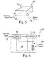
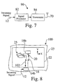
- a user can place a piece of paper 22 of any size on a flat surface 24 such as a table or floor, and the printhead 18 is propelled across the surface 24 and is directed by signals 16 beamed between the print head 18 and a control mechanism 14.
- a large-surface-area plotting system 10 is provided in the form of a small hand-held device.
- a detection system 50 on the printhead 18 is used to receive the combined input signal 16 from the remote transmitter 14, isolate the printhead coordinate 64, 66 and pen activation 68 signals from each other, and process them independently to determine the desired location of the printhead 18 and of the position of the pointing tip 21 of the pen 20.
- the remote plotting process comprises the following steps:
- the pen 20 has a pointing tip 21, which comes into contact with a recording medium 22 when the pen 20 is in the "pen down” position, and is moved away from contacting the recording medium 22 when the pen 20 is in the "pen up” position. While Figure 2 shows only one pen 20, alternate printheads 18 hold multiple pens and activation devices simultaneously. Multiple pens 20 are used to plot images 25 having multiple colors, or are used to plot images having different line widths. In other embodiments, one or more inkjet pens 20 are used, wherein the activation device 46 is used to selectively activate the pens 20 to spray ink or toner.
- FIG 3 is a functional block diagram 30 of a robotic plotter printhead 18.
- the printhead 18 can be powered from a number of sources 34, including but not limited to replaceable batteries, rechargeable batteries, or solar cells.
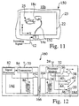
- a stationary primary coil 162 is included in the plotter transmitter module 14.
- the stationary primary coil 162 provides power, through inductive coupling 166, to a recharge coil 164 located within the robotic plotter printhead 18d, when the robotic plotter printhead 18d is stored in a home position next to the plotter transmitter module 14.
- the recharge coil 164 is connected to the rechargeable battery power source 34 within the robotic plotter printhead 18.
- Input signals 16 enter the processor module 32 through the receiver antenna 24.
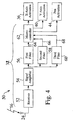
- the processor module 32 includes both signal receiving and processing capabilities, as shown in Figure 4.
- Supply power for controlled movement in the X direction 36 is fed to a stepper motor 38 which is used to activate rollers 26 that guide the robotic plotter printhead 18 in the X direction.
- Supply power for controlled movement in the Y direction 40 is fed to a stepper motor 42 which is used to activate rollers 28 that guide the robotic plotter printhead 18 in the Y direction.
- a single drive system 26 can be used, having a drive motor and a means for selectively directing the robotic plotter printhead 18 in any direction across the X - Y plane of the recording medium.
- Supply power is fed to an activation device 46, for the controlled activation 44 of the pen between a "pen up” position and a “pen down” position, which moves the pen tip 21 into contact with or away from an output medium 22.
- Figure 4 is a flow chart of the detection system 50, which illustrates how the ranging input signal 16 from a plotter transmitter module 14 into a robotic plotter printhead 18 is processed.
- An incoming signal 16 enters the receiver 52 through the receiver antenna 24, and is amplified by the signal amplifier 54.
- the input signal 16 contains signals of distinct frequencies, which communicates X information, Y information, and pen activation information simultaneously.
- the detection system 50 isolates the input signals 64, 66 and 68 from each other, using bandwidth filters 56, 58 and 60, and processes them independently, within a microcontroller 62.
- the microcontroller 62 selectively and simultaneously produces activation signals 36, 40 and 44 to control the movement of the robotic plotter printhead 18 in the X and Y direction, and the activation of the pen 20, upon the surface of a recording medium 22.
- robotic plotting system and its methods of use are described herein in connection with plotting onto a recording medium, the apparatus techniques can be implemented for other input or output display devices, or any combination thereof, as desired.
Landscapes
- Engineering & Computer Science (AREA)
- Physics & Mathematics (AREA)
- General Physics & Mathematics (AREA)
- Theoretical Computer Science (AREA)
- Human Computer Interaction (AREA)
- General Engineering & Computer Science (AREA)
- Automation & Control Theory (AREA)
- Manipulator (AREA)
- Printers Characterized By Their Purpose (AREA)
Abstract
Description
Claims (20)
- A robotic plotting printhead (18) for use with a first transmitting element (14) adapted to provide a combined input signal (16) comprising a plurality of distinct frequencies that communicate a printhead coordinate input signal (64, 66) and a pen activation input signal (68), the printhead (18) comprising:a receiver element (32) adapted to receive the combined input signal (16), the receiver element (32) comprising a detection system (50) having a plurality of bandwidth filters (56, 58, 60) for isolating the printhead coordinate input signal (64, 66) and the pen activation input signal (68);a microcontroller (62) for independently processing the isolated printhead coordinate input signal (64, 66) and the pen activation input signal (68) to selectively and simultaneously produce a printhead coordinate activation signal (36, 40) and a pen activation signal (44);a motorized drive system (26, 28, 38) coupled to the microcontroller (62) and directed by the printhead coordinate activation signal (36, 40) for propelling the robotic plotting printhead (18) across a recording medium (22) in a controlled manner; andan activatable pen tip (21) activated by the pen activation signal (44) through the microcontroller (62) for writing onto the recording medium (22).
- The printhead (18) of claim 1, wherein the recording medium (22) is substantially planar.
- The printhead (18) of claim 1, wherein the first transmitting element (14) is located along the periphery of the recording medium (22).
- The printhead (18) of claim 1, wherein the combined input signal (16) comprises a microwave control signal.
- The printhead (18) of claim 1, wherein the combined input signal (16) comprises an ultrasonic control signal.
- The printhead (18) of claim 1, wherein the combined input signal (16) comprises an infrared control signal.
- The printhead (18) of claim 1, further comprising a printhead transmitter element (112) adapted to transmit a homing signal to the first transmitting element (14).
- The printhead (18) of claim 1, further comprising a printhead transmitter element (112) adapted to transmit a homing signal to a pointer benchmark.
- The printhead (18) of claim 1, further comprising a portable power source (34) connected to the receiver element (32), the detection system (50), the motorized drive system(26, 28, 38), and the activatable pen tip (21).
- The printhead (18) of claim 1, further comprising a flexible power lead (152) tethered between the printhead (18)and the first transmitting element (14).
- A system (120) for use with the printhead (18) of claim 1, the system (120) comprising:a second transmitting element (132) adapted to produce a time-synchronized presentation output signal (127) in response to a written image (123) entered by a user at a first site (124);a network (134) adapted to send the presentation output signal (127) from the first site (124) to a second site (136); anda plotter transmitter module (14) at the second site (136) adapted to receive the presentation output signal (127) and generate therefrom the combined input signal (16) in response to the received presentation output signal (127).
- The system (120) of claim 11, further comprising:a sound recording system (128, 130) adapted to produce a sound output signal (131) in response to sounds entered by the user at the first site (124), wherein the network (134) is adapted to send both the presentation output signal (127) and the sound output signal (131) from the first site (124) to the second site (136); anda sound presentation system (140) at the second site (136) adapted to receive the sound output signal (131) from the first site (124), and present the sound signal at the second site (136).
- The system (120) of claim 11, wherein the plotter transmitter module (14) is located along the periphery of the recording medium (22).
- The system (120) of claim 11, wherein the combined input signal (16) comprises a microwave control signal.
- The system (120) of claim 11, wherein the combined input signal (16) comprises an ultrasonic control signal.
- The system (120) of claim 11, wherein the combined input signal (16) comprises an infrared control signal.
- A method comprising:inputting a combined plotter signal (16) to a plotter printhead (18) having a pen tip (21), the combined plotter signal (16) comprising a plurality of distinct frequencies which separately communicate X and Y location coordinate input signals (36, 40), and a pen activation input signal (44), in response to a received presentation output signal (12);feeding the combined plotter signal (16) through a plurality of filters (56, 58, 60) to isolate the X and Y location coordinate input signals (36, 40) and the pen activation input signal (44);independently processing the X and Y location component input signals (36, 40) and the pen activation input signal (44) to selectively and simultaneously produce X and Y location coordinate activation signals (64, 66) and a pen activation signal (68);selectively directing the plotter printhead (18) across a recording medium (22) in response to the X and Y location coordinate activation signals (64, 66); andselectively moving the pen tip (21) into contact with or away from the recording medium (22) in response to the pen activation signal (68).
- The method of claim 17, further comprising amplifying the combined plotter signal (16).
- The method of claim 17, wherein the combined plotter signal (16) comprises an ultrasonic signal.
- The method of claim 17, wherein the combined plotter signal (16) comprises an infrared signal.
Applications Claiming Priority (3)
| Application Number | Priority Date | Filing Date | Title |
|---|---|---|---|
| US08/993,819 US6116707A (en) | 1997-12-18 | 1997-12-18 | Robotic plotter system |
| US993819 | 1997-12-18 | ||
| PCT/US1998/021007 WO1999031466A2 (en) | 1997-12-18 | 1998-10-01 | Robotic plotter system |
Publications (2)
| Publication Number | Publication Date |
|---|---|
| EP1040320A2 EP1040320A2 (en) | 2000-10-04 |
| EP1040320B1 true EP1040320B1 (en) | 2005-04-27 |
Family
ID=25539969
Family Applications (1)
| Application Number | Title | Priority Date | Filing Date |
|---|---|---|---|
| EP98952093A Expired - Lifetime EP1040320B1 (en) | 1997-12-18 | 1998-10-01 | Robotic plotter |
Country Status (11)
| Country | Link |
|---|---|
| US (1) | US6116707A (en) |
| EP (1) | EP1040320B1 (en) |
| JP (1) | JP2002508269A (en) |
| AT (1) | ATE294375T1 (en) |
| AU (1) | AU729474B2 (en) |
| BR (1) | BR9813739A (en) |
| CA (1) | CA2313455A1 (en) |
| DE (1) | DE69829997T2 (en) |
| IL (1) | IL136772A0 (en) |
| NZ (1) | NZ505235A (en) |
| WO (1) | WO1999031466A2 (en) |
Families Citing this family (38)
| Publication number | Priority date | Publication date | Assignee | Title |
|---|---|---|---|---|
| GB2343658B (en) | 1998-11-13 | 2002-07-31 | Esselte Nv | A printer with variable friction between printer and a medium |
| EP1101620A1 (en) | 1999-11-22 | 2001-05-23 | Howard H. Bobry | Multiple path raster scan printing head control system |
| US6457792B1 (en) * | 1999-11-29 | 2002-10-01 | Xerox Corporation | Method for effecting actions over vertical surfaces |
| US6367902B1 (en) | 1999-11-29 | 2002-04-09 | Xerox Corporation | Effector platform for performing actions over vertical surfaces |
| US6931304B1 (en) * | 2000-03-28 | 2005-08-16 | Storage Technology Corporation | Scalable means of supplying power to a remotely controlled, semi-autonomous robot |
| IL141300A0 (en) | 2001-02-07 | 2002-03-10 | Kandelshein Menachem | A method and apparatus for flat surface treatment |
| US6695445B2 (en) | 2001-11-13 | 2004-02-24 | Primera Technology, Inc. | Printer for large sheets of print media |
| US20040027414A1 (en) * | 2002-08-12 | 2004-02-12 | Miguel Boleda | Printing on surfaces |
| US6729706B1 (en) | 2003-02-14 | 2004-05-04 | Eastman Kodak Company | Large area marking device and method for printing |
| AU2003900861A0 (en) * | 2003-02-26 | 2003-03-13 | Silverbrook Research Pty Ltd | Methods,systems and apparatus (NPS042) |
| US6951375B2 (en) * | 2003-05-20 | 2005-10-04 | Eastman Kodak Company | Large area marking device and method for printing |
| JP2007520374A (en) * | 2004-01-15 | 2007-07-26 | コーニンクレッカ フィリップス エレクトロニクス エヌ ヴィ | Electronic paint brush with scanner and applicator |
| DE102004005899A1 (en) * | 2004-02-05 | 2005-09-01 | Vodafone Holding Gmbh | communication system |
| US7317331B2 (en) * | 2004-11-08 | 2008-01-08 | Tabula, Inc. | Reconfigurable IC that has sections running at different reconfiguration rates |
| CA2527458C (en) | 2004-11-25 | 2016-08-30 | Unotchit Inc. | Apparatus and method for optimized tracing of a pattern on a surface |
| US20070105626A1 (en) | 2005-08-19 | 2007-05-10 | Nintendo Software Technology Corporation | Touch screen inputs for a video game system |
| US20070076082A1 (en) * | 2005-09-30 | 2007-04-05 | Lexmark International, Inc. | Methods and apparatuses for measuring print area using hand-held printer |
| US20070139508A1 (en) * | 2005-12-21 | 2007-06-21 | Muyskens Robert H | Hand-held ink jet printer |
| DE102006010715A1 (en) * | 2006-03-08 | 2008-06-19 | Bernd Hoyer | Equipment processing and marking static articles, has small unit sliding on or over workpiece without making contact, on e.g. air cushion- or magnetic bearing |
| US7784933B2 (en) * | 2006-06-29 | 2010-08-31 | Lexmark International, Inc. | Smart projector guides for handprinters |
| US8758076B1 (en) | 2006-07-31 | 2014-06-24 | Gwen Austin | Radio controlled toy for free form drawing |
| US8411053B2 (en) * | 2008-12-18 | 2013-04-02 | Einstruction Corporation | Dual pen interactive whiteboard system |
| KR101599876B1 (en) * | 2009-04-15 | 2016-03-14 | 삼성전자주식회사 | Handheld printer and printing method thereof |
| PE20110872A1 (en) * | 2010-04-05 | 2011-12-30 | Manyari Jorge Alfonso Jesus Vallejo | BLACKBOARD THAT DESCRIBES OR REPRESENTS REALITY IN ITS FOUR DIMENSIONS, UNIVERSAL GRAPHER AND INSTRUMENT FOR LEARNING AND SCIENTIFIC MEASUREMENT |
| US8646874B2 (en) * | 2011-11-30 | 2014-02-11 | Eastman Kodak Company | Adaptive motion control for carriage printer |
| US8585178B2 (en) * | 2011-11-30 | 2013-11-19 | Eastman Kodak Company | Carriage printer with adaptive motion control |
| US8696089B2 (en) * | 2012-06-11 | 2014-04-15 | Xerox Corporation | Portable printer for direct imaging on surfaces |
| US20140144376A1 (en) * | 2012-11-28 | 2014-05-29 | Gregory Michael Burke | Mobile apparatus with local position referencing elements |
| US9046346B2 (en) | 2012-11-28 | 2015-06-02 | Eastman Kodak Company | Determining a position of a mobile apparatus |
| US8724118B1 (en) | 2012-11-28 | 2014-05-13 | Eastman Kodak Company | Mobile apparatus with local position referencing structure |
| GB2537334A (en) * | 2014-01-24 | 2016-10-12 | Zuta Labs Ltd | Self-propelled printer and self-propelled imprinter |
| US9849693B1 (en) * | 2016-08-31 | 2017-12-26 | Fuji Xerox Co., Ltd. | Systems and methods for printing on large surface with portable printing devices |
| IT201800004529A1 (en) * | 2018-04-16 | 2019-10-16 | Vertical plotter with improved print head | |
| CN109087371B (en) * | 2018-07-16 | 2023-06-30 | 深圳市智能机器人研究院 | A method and system for controlling a robot portrait |
| CN109278424A (en) * | 2018-11-23 | 2019-01-29 | 北京小米移动软件有限公司 | Printers and Printer Systems |
| US12059891B2 (en) | 2019-10-17 | 2024-08-13 | Zuta Labs Ltd | Autonomously moving multifunctional robotic device with printer |
| US20240371188A1 (en) * | 2021-04-23 | 2024-11-07 | 3M Innovative Properties Company | Systems and methods for managing digital notes for project planning |
| EP4360903A1 (en) * | 2022-10-27 | 2024-05-01 | BIC Violex Single Member S.A. | Drawing system |
Citations (1)
| Publication number | Priority date | Publication date | Assignee | Title |
|---|---|---|---|---|
| US6415040B1 (en) * | 1997-05-29 | 2002-07-02 | Koninklijke Philips Electronics N.V. | Device for optically scanning a record carrier |
Family Cites Families (9)
| Publication number | Priority date | Publication date | Assignee | Title |
|---|---|---|---|---|
| US3706850A (en) * | 1971-04-23 | 1972-12-19 | Bell Telephone Labor Inc | Telewriting system |
| JPS56162660A (en) * | 1980-05-21 | 1981-12-14 | Fujitsu Ltd | Self-propelled plotting device |
| EP0094737A3 (en) * | 1982-03-29 | 1986-02-12 | Penman Products Limited | Self-propelled drawing device or tracing device |
| US4615040A (en) * | 1984-06-14 | 1986-09-30 | Coenco Ltd. | High speed data communications system |
| JPS6443855A (en) * | 1987-08-11 | 1989-02-16 | Canon Kk | Recording device |
| JP2549448B2 (en) * | 1990-03-20 | 1996-10-30 | 株式会社ピーエフユー | Mouse type self-propelled plotter |
| US5222138A (en) * | 1992-08-06 | 1993-06-22 | Balabon Sam D | Remote signature rendering system & apparatus |
| US5446559A (en) * | 1992-10-05 | 1995-08-29 | Hewlett-Packard Company | Method and apparatus for scanning and printing |
| US5686938A (en) * | 1995-06-29 | 1997-11-11 | Batkhan; Leonid Z. | Adaptive cursor control system |
-
1997
- 1997-12-18 US US08/993,819 patent/US6116707A/en not_active Expired - Lifetime
-
1998
- 1998-10-01 JP JP2000539321A patent/JP2002508269A/en active Pending
- 1998-10-01 EP EP98952093A patent/EP1040320B1/en not_active Expired - Lifetime
- 1998-10-01 DE DE69829997T patent/DE69829997T2/en not_active Expired - Fee Related
- 1998-10-01 AU AU97871/98A patent/AU729474B2/en not_active Ceased
- 1998-10-01 BR BR9813739-5A patent/BR9813739A/en not_active IP Right Cessation
- 1998-10-01 CA CA002313455A patent/CA2313455A1/en not_active Abandoned
- 1998-10-01 NZ NZ505235A patent/NZ505235A/en unknown
- 1998-10-01 IL IL13677298A patent/IL136772A0/en unknown
- 1998-10-01 AT AT98952093T patent/ATE294375T1/en not_active IP Right Cessation
- 1998-10-01 WO PCT/US1998/021007 patent/WO1999031466A2/en not_active Ceased
Patent Citations (1)
| Publication number | Priority date | Publication date | Assignee | Title |
|---|---|---|---|---|
| US6415040B1 (en) * | 1997-05-29 | 2002-07-02 | Koninklijke Philips Electronics N.V. | Device for optically scanning a record carrier |
Also Published As
| Publication number | Publication date |
|---|---|
| BR9813739A (en) | 2000-11-07 |
| ATE294375T1 (en) | 2005-05-15 |
| JP2002508269A (en) | 2002-03-19 |
| AU9787198A (en) | 1999-07-05 |
| AU729474B2 (en) | 2001-02-01 |
| WO1999031466A3 (en) | 1999-08-12 |
| US6116707A (en) | 2000-09-12 |
| EP1040320A2 (en) | 2000-10-04 |
| NZ505235A (en) | 2002-07-26 |
| WO1999031466A2 (en) | 1999-06-24 |
| DE69829997D1 (en) | 2005-06-02 |
| CA2313455A1 (en) | 1999-06-24 |
| DE69829997T2 (en) | 2006-02-23 |
| IL136772A0 (en) | 2001-06-14 |
Similar Documents
| Publication | Publication Date | Title |
|---|---|---|
| US6116707A (en) | Robotic plotter system | |
| US5446559A (en) | Method and apparatus for scanning and printing | |
| JP2002307756A (en) | How to print an image on the surface of a medium | |
| JP4390582B2 (en) | Electronic stylus and method for determining position of tip of stylus | |
| US6517266B2 (en) | Systems and methods for hand-held printing on a surface or medium | |
| US7203383B2 (en) | Handwritten character recording and recognition device | |
| ZA200603310B (en) | Method of employing a chirographic stylus | |
| WO2009042949A1 (en) | Handwriting capture for determining absolute position within a form layout using pen position triangulation | |
| US7842893B2 (en) | Electronic pen having an ultrasonic wave controller | |
| EP1668565B1 (en) | Method of employing a chirographic stylus | |
| US4528754A (en) | Self-propelled drawing device or tracing device | |
| EP1018428A4 (en) | Large format ink-jet colour printer | |
| US5896471A (en) | Device for inputting and outputting image data | |
| EP1380006B1 (en) | Handwritten character recording and recognition device | |
| CN111137016A (en) | Universal printing head device with multiple sensors | |
| CN110027328A (en) | The hand-held mobile printing equipment of one kind | |
| CN206019661U (en) | Virtual reality attitude and coordinate passive measurement device | |
| JPH08142584A (en) | Recording device | |
| US20050134928A1 (en) | Reference marking system and tracking system for large area printing | |
| CN220438549U (en) | Handheld three-dimensional perspective radar | |
| CN217728742U (en) | Intelligent interactive robot | |
| JPH0931731A (en) | Image forming device | |
| JPH0816306A (en) | Optical position detector | |
| JP2809220B2 (en) | Image input synthesis device | |
| JP2002149238A (en) | Recording method and apparatus |
Legal Events
| Date | Code | Title | Description |
|---|---|---|---|
| PUAI | Public reference made under article 153(3) epc to a published international application that has entered the european phase |
Free format text: ORIGINAL CODE: 0009012 |
|
| 17P | Request for examination filed |
Effective date: 20000615 |
|
| AK | Designated contracting states |
Kind code of ref document: A2 Designated state(s): AT BE CH CY DE DK ES FI FR GB GR IE IT LI LU MC NL PT SE |
|
| 17Q | First examination report despatched |
Effective date: 20031021 |
|
| GRAP | Despatch of communication of intention to grant a patent |
Free format text: ORIGINAL CODE: EPIDOSNIGR1 |
|
| GRAS | Grant fee paid |
Free format text: ORIGINAL CODE: EPIDOSNIGR3 |
|
| GRAA | (expected) grant |
Free format text: ORIGINAL CODE: 0009210 |
|
| AK | Designated contracting states |
Kind code of ref document: B1 Designated state(s): AT BE CH CY DE DK ES FI FR GB GR IE IT LI LU MC NL PT SE |
|
| PG25 | Lapsed in a contracting state [announced via postgrant information from national office to epo] |
Ref country code: LI Free format text: LAPSE BECAUSE OF FAILURE TO SUBMIT A TRANSLATION OF THE DESCRIPTION OR TO PAY THE FEE WITHIN THE PRESCRIBED TIME-LIMIT Effective date: 20050427 Ref country code: IT Free format text: LAPSE BECAUSE OF FAILURE TO SUBMIT A TRANSLATION OF THE DESCRIPTION OR TO PAY THE FEE WITHIN THE PRESCRIBED TIME-LIMIT;WARNING: LAPSES OF ITALIAN PATENTS WITH EFFECTIVE DATE BEFORE 2007 MAY HAVE OCCURRED AT ANY TIME BEFORE 2007. THE CORRECT EFFECTIVE DATE MAY BE DIFFERENT FROM THE ONE RECORDED. Effective date: 20050427 Ref country code: FI Free format text: LAPSE BECAUSE OF FAILURE TO SUBMIT A TRANSLATION OF THE DESCRIPTION OR TO PAY THE FEE WITHIN THE PRESCRIBED TIME-LIMIT Effective date: 20050427 Ref country code: ES Free format text: LAPSE BECAUSE OF FAILURE TO SUBMIT A TRANSLATION OF THE DESCRIPTION OR TO PAY THE FEE WITHIN THE PRESCRIBED TIME-LIMIT Effective date: 20050427 Ref country code: CH Free format text: LAPSE BECAUSE OF FAILURE TO SUBMIT A TRANSLATION OF THE DESCRIPTION OR TO PAY THE FEE WITHIN THE PRESCRIBED TIME-LIMIT Effective date: 20050427 Ref country code: BE Free format text: LAPSE BECAUSE OF FAILURE TO SUBMIT A TRANSLATION OF THE DESCRIPTION OR TO PAY THE FEE WITHIN THE PRESCRIBED TIME-LIMIT Effective date: 20050427 Ref country code: AT Free format text: LAPSE BECAUSE OF FAILURE TO SUBMIT A TRANSLATION OF THE DESCRIPTION OR TO PAY THE FEE WITHIN THE PRESCRIBED TIME-LIMIT Effective date: 20050427 |
|
| REG | Reference to a national code |
Ref country code: GB Ref legal event code: FG4D |
|
| REG | Reference to a national code |
Ref country code: CH Ref legal event code: EP |
|
| REG | Reference to a national code |
Ref country code: IE Ref legal event code: FG4D |
|
| REF | Corresponds to: |
Ref document number: 69829997 Country of ref document: DE Date of ref document: 20050602 Kind code of ref document: P |
|
| PG25 | Lapsed in a contracting state [announced via postgrant information from national office to epo] |
Ref country code: SE Free format text: LAPSE BECAUSE OF FAILURE TO SUBMIT A TRANSLATION OF THE DESCRIPTION OR TO PAY THE FEE WITHIN THE PRESCRIBED TIME-LIMIT Effective date: 20050727 Ref country code: GR Free format text: LAPSE BECAUSE OF FAILURE TO SUBMIT A TRANSLATION OF THE DESCRIPTION OR TO PAY THE FEE WITHIN THE PRESCRIBED TIME-LIMIT Effective date: 20050727 Ref country code: DK Free format text: LAPSE BECAUSE OF FAILURE TO SUBMIT A TRANSLATION OF THE DESCRIPTION OR TO PAY THE FEE WITHIN THE PRESCRIBED TIME-LIMIT Effective date: 20050727 |
|
| PG25 | Lapsed in a contracting state [announced via postgrant information from national office to epo] |
Ref country code: GB Free format text: LAPSE BECAUSE OF NON-PAYMENT OF DUE FEES Effective date: 20051001 Ref country code: CY Free format text: LAPSE BECAUSE OF FAILURE TO SUBMIT A TRANSLATION OF THE DESCRIPTION OR TO PAY THE FEE WITHIN THE PRESCRIBED TIME-LIMIT Effective date: 20051001 |
|
| PG25 | Lapsed in a contracting state [announced via postgrant information from national office to epo] |
Ref country code: IE Free format text: LAPSE BECAUSE OF NON-PAYMENT OF DUE FEES Effective date: 20051003 |
|
| PG25 | Lapsed in a contracting state [announced via postgrant information from national office to epo] |
Ref country code: PT Free format text: LAPSE BECAUSE OF FAILURE TO SUBMIT A TRANSLATION OF THE DESCRIPTION OR TO PAY THE FEE WITHIN THE PRESCRIBED TIME-LIMIT Effective date: 20051010 |
|
| PG25 | Lapsed in a contracting state [announced via postgrant information from national office to epo] |
Ref country code: MC Free format text: LAPSE BECAUSE OF NON-PAYMENT OF DUE FEES Effective date: 20051031 Ref country code: LU Free format text: LAPSE BECAUSE OF NON-PAYMENT OF DUE FEES Effective date: 20051031 |
|
| REG | Reference to a national code |
Ref country code: CH Ref legal event code: PL |
|
| ET | Fr: translation filed | ||
| PLBE | No opposition filed within time limit |
Free format text: ORIGINAL CODE: 0009261 |
|
| STAA | Information on the status of an ep patent application or granted ep patent |
Free format text: STATUS: NO OPPOSITION FILED WITHIN TIME LIMIT |
|
| 26N | No opposition filed |
Effective date: 20060130 |
|
| PG25 | Lapsed in a contracting state [announced via postgrant information from national office to epo] |
Ref country code: NL Free format text: LAPSE BECAUSE OF NON-PAYMENT OF DUE FEES Effective date: 20060501 |
|
| PG25 | Lapsed in a contracting state [announced via postgrant information from national office to epo] |
Ref country code: DE Free format text: LAPSE BECAUSE OF NON-PAYMENT OF DUE FEES Effective date: 20060503 |
|
| GBPC | Gb: european patent ceased through non-payment of renewal fee |
Effective date: 20051001 |
|
| NLV4 | Nl: lapsed or anulled due to non-payment of the annual fee |
Effective date: 20060501 |
|
| REG | Reference to a national code |
Ref country code: IE Ref legal event code: MM4A |
|
| PG25 | Lapsed in a contracting state [announced via postgrant information from national office to epo] |
Ref country code: FR Free format text: LAPSE BECAUSE OF NON-PAYMENT OF DUE FEES Effective date: 20051031 |
|
| REG | Reference to a national code |
Ref country code: FR Ref legal event code: ST Effective date: 20111125 |