EP1039659A2 - Lastverteilungsverfahren zur Besserung des Spielraums kombinierter FDMA/TDMA Aufwärtssignale - Google Patents
Lastverteilungsverfahren zur Besserung des Spielraums kombinierter FDMA/TDMA Aufwärtssignale Download PDFInfo
- Publication number
- EP1039659A2 EP1039659A2 EP00105736A EP00105736A EP1039659A2 EP 1039659 A2 EP1039659 A2 EP 1039659A2 EP 00105736 A EP00105736 A EP 00105736A EP 00105736 A EP00105736 A EP 00105736A EP 1039659 A2 EP1039659 A2 EP 1039659A2
- Authority
- EP
- European Patent Office
- Prior art keywords
- signal
- satellite
- power level
- uplink
- carrier channels
- Prior art date
- Legal status (The legal status is an assumption and is not a legal conclusion. Google has not performed a legal analysis and makes no representation as to the accuracy of the status listed.)
- Granted
Links
- 238000000034 method Methods 0.000 title claims abstract description 31
- 238000004891 communication Methods 0.000 claims abstract description 60
- 230000007423 decrease Effects 0.000 claims abstract description 6
- 230000001965 increasing effect Effects 0.000 claims description 11
- 230000005540 biological transmission Effects 0.000 claims description 9
- 239000002131 composite material Substances 0.000 claims description 6
- 230000003247 decreasing effect Effects 0.000 claims description 2
- 230000002708 enhancing effect Effects 0.000 claims description 2
- 230000001186 cumulative effect Effects 0.000 claims 2
- 238000012545 processing Methods 0.000 description 15
- 230000010267 cellular communication Effects 0.000 description 10
- 238000010586 diagram Methods 0.000 description 8
- 239000000969 carrier Substances 0.000 description 7
- 238000005562 fading Methods 0.000 description 7
- 230000009471 action Effects 0.000 description 4
- 230000000694 effects Effects 0.000 description 3
- 230000003595 spectral effect Effects 0.000 description 3
- 230000008901 benefit Effects 0.000 description 2
- 230000000116 mitigating effect Effects 0.000 description 2
- 230000004044 response Effects 0.000 description 2
- 230000009172 bursting Effects 0.000 description 1
- 230000008859 change Effects 0.000 description 1
- 238000010276 construction Methods 0.000 description 1
- 238000012423 maintenance Methods 0.000 description 1
- 238000012986 modification Methods 0.000 description 1
- 230000004048 modification Effects 0.000 description 1
- 238000012544 monitoring process Methods 0.000 description 1
- 230000000737 periodic effect Effects 0.000 description 1
- 230000010287 polarization Effects 0.000 description 1
- 238000012552 review Methods 0.000 description 1
- 238000000926 separation method Methods 0.000 description 1
- 230000002459 sustained effect Effects 0.000 description 1
- 238000012546 transfer Methods 0.000 description 1
Images


Classifications
-
- H—ELECTRICITY
- H04—ELECTRIC COMMUNICATION TECHNIQUE
- H04B—TRANSMISSION
- H04B7/00—Radio transmission systems, i.e. using radiation field
- H04B7/14—Relay systems
- H04B7/15—Active relay systems
- H04B7/185—Space-based or airborne stations; Stations for satellite systems
- H04B7/1851—Systems using a satellite or space-based relay
- H04B7/18513—Transmission in a satellite or space-based system
Definitions
- This invention relates generally to a communications system and, more particularly, to a load shedding method to enhance uplink margin with combined FDMA/TDMA uplinks in a satellite based cellular communications system.
- a central terrestrial control processor or network operations center generally controls one or more communications satellites operating within the communications system.
- Each communications satellite within the communications system services multiple users located in multiple geographic areas, known as ground cells.
- the communications satellites receive and transmit data signals to and from the multiple users or terrestrial terminals positioned at the different locations within the separate ground cells on a point-to-point manner.
- FDMA frequency division multiple access
- TDMA time division multiple access
- An antenna on each communications satellite generates a multitude of spot beams to illuminate a surface on the earth where the ground cells are located in order to accommodate the re-use of the frequencies throughout the communications system.
- Antenna patterns for each spot beam covering each ground cell typically roll off very fast towards the edge of the beam, and thus with even small antenna or satellite pointing errors, the user on the ground may see significant signal attenuation due to this mispointing.
- modem satellite communications systems now operate at much higher carrier frequencies (for example, Ka-band), these signals are vulnerable to large attenuations due to rain, scintillation, and other atmospheric effects. Because of this, the terrestrial user terminals will have degraded performance unless attenuation mitigation is employed.
- a load shedding method to enhance uplink margin between a terrestrial terminal and a satellite in a satellite based cellular communications system is provided.
- the load shedding method provides a means to efficiently and cost effectively provide enhanced uplink margin by utilizing multiple uplink carrier channels simultaneously.
- the power level of the carrier channels or number of carrier channels may then be adjusted depending on the particular attenuation levels.
- a load shedding method to enhance uplink margin between a terrestrial terminal and a satellite in a satellite based communications system includes generating a first signal having a first carrier channel and a second signal having a second carrier channel.
- the first signal having the first carrier channel and the second signal having the second carrier channel are transmitted from the terrestrial terminal to the satellite.
- a transmit power level of the first signal and the second signal transmitted from the terrestrial transmitter is determined and a received power level of the first signal and the second signal received at the satellite is determined. Transmission of the second signal having the second carrier channel is terminated when the transmit power level of the first signal and the second signal transmitted from the terrestrial terminal exceeds a first threshold.
- a load shedding method to enhance uplink margin between a terrestrial terminal and a satellite in a satellite based communication system includes generating a plurality of uplink carrier channels.
- the plurality of uplink carrier channels are transmitted from the terrestrial terminal to the satellite.
- a transmit power level and a receive power level of the plurality of uplink carrier channels are determined.
- An attenuation level on the plurality of uplink carrier channels based upon the transmit power level and the receive power level is also determined.
- the transmit power level of the plurality of uplink carrier channels is adjusted based upon the attenuation level.
- a terrestrial terminal for enhancing uplink margin between the terrestrial terminal and a satellite in a satellite based communication system includes a multi-carrier network operable to generate a plurality of uplink carrier channels.
- An RF transmit and receive system transmits the plurality of uplink carrier channels to the satellite.
- a terminal control unit determines an attenuation level on the plurality of uplink carrier channels transmitted to the satellite and instructs the multi-carrier network to increase or decrease the number of uplink carrier channels to be transmitted.
- the communications system 10 includes one or more processing communications satellites 12 operating generally in geosynchronous orbits. Each communications satellite 12 supports multiple terrestrial user terminals 14 positioned within various defined ground cells, further discussed herein. Each communications satellite 12 receives data signals from the user terminals 14 on communications uplinks 16 and transmits data signals to the user terminals 14 on communications downlinks 18. Each user terminal 14 transmits data signals on the communications uplinks 16 which may include multiple carrier channels and receives data signals on the communications downlinks 18, via an antenna 20. Each communications satellite 12 receives and transmits the data signals on the communications uplinks 16 and the communications downlinks 18, via a multi-beam antenna 22 or any other appropriate antenna to service the required region.
- the satellite based cellular communications system 10 also includes a network operations center (NOC) 24 which includes a central control processor 26.
- the network operations center 24 generally controls the overall operations of each communications satellite 12 utilizing communications uplinks 16 and communications downlinks 18, via an antenna 28. These overall operations include maintenance of the geosynchronous orbit, positioning of solar collectors 29, initializing satellite system parameters, user billing, as well as other operational controls which are all well known in the art.
- the central control processor 26 in the network operations center 24 is preferably a general purpose programmable computer of appropriate computational power.
- a processing communications satellite 12 is shown illuminating a coverage region 30, via antenna 22.
- the communications satellite 12 services the coverage region 30 which includes multiple ground cells 32 represented by each circular region.
- Each of the ground cells 32 is shown positioned within a hexagonal shaped region 34 which are the regions each individually illuminated by one antenna beam from the multi-beam antenna 22 on the communications satellite 12.
- Each ground cell 32 typically measures approximately 300 to 400 miles in diameter and is generally measured as the shortest distance between two points where the antenna gain is minimally acceptable. For example, this may be a point at which the antenna gain drops off by 5 or 6 dB.
- the coverage region 30 is shown utilizing what is known as a 4-to-1 reuse where the coverage region 30 is separated into one of four types of ground cells 32a-32d. Of course, any other type of reuse pattern may also be employed.
- Each of the ground cells 32 having the same shading operate within the same frequency band. Within each particular frequency band, many different carrier frequencies or channels (carrier channels) are available to user terminals 14 operating within these ground cells 32.
- each of the ground cells 32a may be allocated a first 100 MHz frequency band that is divided into 200 carrier channels. In this way, user terminal 14a within the ground cell 32a is allocated at least one of the 200 carrier channels and at least one of the time slots allocated to that particular carrier channel.
- each of the ground cells 32b may be allocated a second 100 MHz frequency band
- each of the ground cells 32c may be allocated a third 100 MHz frequency band
- each of the ground cells 32d may be allocated a fourth 100 MHz frequency band.
- all of the ground cells identified as 32a will be operated within the same 100 MHz frequency band having the same 200 carder channel available and so forth throughout each set of ground cells 32 within the coverage region 30.
- User terminal 14a in ground cell 32a is operating within the first 100 MHz frequency band and say, for example, carrier channel one within this 100 MHz frequency band.
- the communications uplink 16a originating from user terminal 14a is directed into a main beam 36 of the multibeam antenna 22 servicing ground cell 32a.
- User terminal 14a is also bursting on and off within a particular time slot for carrier channel one within the 100 MHz frequency band.
- User terminal 14a may also use additional carrier channels within the 100 MHz frequency band and/or additional time slots depending on how much bandwidth the user terminal 14a requires to transmit all its data, via communications uplink 16a. Should the user terminal 14a use additional carrier channels, the load shedding method to enhance uplink margin according to the teachings of the present invention may be employed, further discussed herein.
- Each of the communications downlinks 18 from the communications satellite 12 to the multiple user terminals 14 within each group of ground cells 32a-32d operate on a single carrier frequency or channel and is generally always on. In other words, all of the ground cells 32a operate on a first carrier frequency, all of the ground cells 32b operate on a second carrier frequency and so forth.
- the reason for the single carrier frequency being used for each group of ground cells 32a-32d on the communications downlinks 18 is because of the limited power constraints associated with operating the processing communications satellite 12.
- the user terminal 14 includes a multi-carrier network 40 having multiple uplink baseband units (UBU) 42, a downlink baseband unit (DBU) 44, a terminal control unit (TCU) 46, and an RF transmit and receive unit 48, each of which communicate, via a terminal interface bus 50.
- the multi-carrier network 40 include the plurality of uplink baseband units 42 corresponding to the number of carrier channels the particular user terminal 14 will be operating on. For example, three uplink baseband units 42 are shown, each operating at a different carrier frequency (i.e., carriers A, B and C).
- Each uplink baseband unit 42 receives digital data bits or ATM (asynchronous transfer mode) packets, referred to as traffic cells, that include both information data and control commands to adjust IF gain (gain set directives).
- the control commands originate from the terminal control unit 46 and are received from the terminal interface bus 50.
- the information data originates from a user processor (not shown) in communication with the terminal interface bus 50 and may be any type of digital data, including communications data, video data, voice data, etc., which is required to be transferred from one location to another.
- Each uplink baseband unit 42 is conventional in construction and includes a formatter, an error control coder (encoder), a modulator, and an up-convertor.
- the signal formatter formats the signals to the particular format required. For example, in a TDMA system, multiple ATM packets may be combined in a particular time block and appended with a header.
- the error control coder encodes the digital data bits.
- the modulator and the up-converter modulate the encoded digital data bits and up-converts them to an IF (intermediate frequency) uplink signal.
- each uplink baseband unit 42 outputs an IF uplink signal at its particular carrier channel (i.e., A, B or C).
- each IF uplink signal is also adjusted in the uplink baseband unit 42, via commands or instructions (gain set directions) from the terminal control unit 46, further discussed herein.
- Each IF uplink signal from each uplink baseband unit 42a, 42b and 42c are applied to a power combiner 52 which sums each IF uplink signal and generates a composite IF uplink signal having three carrier channels. Once summed, the composite IF uplink signal is delivered from the multi-carrier network 40 to the RF transmit/receive unit 48.
- the RF transmit/receive unit 48 is a conventional RF transmit/receive system.
- the RF transmit/receive unit 48 includes an up-converter portion 54, a down-converter portion 56 and an antenna 58.
- the up-converter portion 54 includes an up-converter (U/C) which receives the composite IF uplink signal and up converts the IF uplink signal to a RF uplink signal.
- the up-converter then applies this composite RF uplink signal to a high power amplifier (HPA), such as a travelling wave tube amplifier (TWTA), which is a non-linear amplifier.
- HPA high power amplifier
- TWTA travelling wave tube amplifier
- the high power amplifier amplifies the RF uplink signal which is subsequently transmitted to the communications processing satellite 12, via the antenna 58.
- the antenna 58 may be any conventional antenna such as a parabolic dish.
- the RF uplink signal is transmitted to the processing communication satellite 12 at a transmit power lever P
- the RF up link signal is received at the processing communications satellite 12 at a received power level P R .
- the processing communication satellite 12 receives the RF uplink signal and transmits RF downlink signals, via the antenna 22, which are received by the antenna 58.
- the RF downlink signals include communications data, video data, voice data or other information data, as well as power control reports that identify the received power level P R .
- the RF downlink signals are applied to the down-converter portion 56 and are first applied to a low noise amplifier (LNA) to amplify the RF downlink signals.
- LNA low noise amplifier
- the amplified RF downlink signals are then down converted in a down-converter (D/C) from an RF frequency to an IF frequency. This IF downlink signal is then applied to the downlink baseband unit 44.
- the downlink baseband unit 44 converts the IF downlink signal to a digital data stream which includes the particular digital information being transferred, as well as the power control reports, identified as report cells.
- the downlink baseband unit 44 may be any conventional downlink baseband unit.
- the downlink baseband unit 44 includes a down-converter, a demodulator, a decoder and a deformatter.
- the demodulator demodulates the signal.
- the down-converter down converts the IF signal.
- the error control decoder decodes the coded data and the deformatter deformats the data into ATM packets.
- the data cells and the report cells from the downlink baseband unit 44 are applied to the terminal interface bus 50.
- the transmit power level P T of the RF uplink signal is forwarded to the terminal control unit 46, which may be any type of microprocessing unit depending on the computational power required.
- the terminal control unit 46 reads the transmit power level P T supplied by the up-converter portion 54 of the RF transmit/receive unit 48.
- the terminal control unit 46 also receives and reads the report cells from the down link baseband unit 44, via the terminal interface bus 50, which identifies the received power level P R . By comparing and taking the difference between the transmit power level P T and the received power level P R from the report cells, the terminal control unit 46 can determine the attenuation or fading level (i.e., P T - P R ) on the RF uplink signal having the composite carrier channels.
- the way the transmit power level P T is controlled for each particular carrier channel is by adjusting the IF power level for each IF uplink carrier channel in the uplink baseband unit 42.
- the terminal control unit 46 instructs the uplink baseband units 42, via gain set directives, which are forwarded to each uplink baseband unit 42 on the terminal interface bus 50.
- the uplink baseband units 42 will then adjust the IF power level based on these instructions which will cause the transmit power level P T to change accordingly.
- the uplink baseband units 42 may terminate transmission of its particular carrier channel should it be instructed by the terminal control unit 46.
- FIG 4 an example of a load shedding method to enhance uplink margin with combined FDMA/TDMA uplinks is shown.
- the horizontal axis represents time and the vertical axis is in decibels (dB) relative to clear sky conditions.
- Various power levels are also noted at the left that represent the thresholds at which carrier channels may be shed or restored depending on the current amount of attenuation or fading being experienced.
- the power levels shown are either the total transmit power P T or the attenuation or fading level (i.e., P T - P R )
- the designed power levels provide for a 4.0dB backoff when two carrier channels are active and a 5.0dB backoff when all three carrier channels are active. It is further assumed that there is a 4.3dB uplink margin under clear sky conditions with all three carrier channels active. The total backoff from saturation of the high power amplifier in the up-converter portion 54, for a single carrier is thus 5.0 + 4.7 + 4.3 or 14.0dB. It should be further understood that the user terminal 14 adjusts the transmit power level P T to try to maintain a constant received power level P R regardless of the location of the user terminal 14, its transmitting characteristics, and any rain or other attenuation that the user terminal 14 is experiencing.
- user terminal 14 adjusts its transmit power level P T for the RF uplink signal in small increments, typically 0.25dB, via the terminal control unit 46 and the uplink baseband units 42, in response to the power control reports from the communications processing satellite 12.
- the transmit power P T is kept close to this level by employing the load shedding method discussed above.
- RF uplink attenuation experienced by the user terminal 14 increases as shown by solid line 62. This increased attenuation is compensated by incrementally increasing the transmit power level P T under the instruction of the terminal control unit 46, as shown by dashed line 64.
- the increase in total transmit power P T continues until the three channel uplink margin of 4.3dB is exhausted, identified by reference numeral 65. At this time, the total transmit power P T from the RF transmit and receive unit 48 has risen to 9.0dB, represented by power threshold P 32 and identified by reference numeral 66. This threshold 66 is 5.0dB below saturation of the high power amplifier in the up-converter portion 54. With continued intensification of the storm 60, the user terminal 14 can no longer accommodate three carrier channels in a linear fashion and so, in response to the next power control report from the processing communication satellite 12, the user terminal 14 sheds load by terminating or turning off carrier channel C at threshold 66 (i.e. P 32 ).
- the attenuation continues to increase (line 62) and the terminal control unit 46 in the user terminal 14 continues to request incremental increases in the transmit power P T , via the uplink baseband units 42 adjusting the IF uplink power levels.
- the transmit power P T at the high power amplifier in the up convertor portion 54 has risen to 10.0dB, which is at the two carrier backoff of 4.0dB below saturation. Further effective increases in the transmit power level cannot be sustained for both carrier channels, such that carrier channel B is turned off at this point, with the effect that the total power drops again, this time by 3.0dB to a level of 7.0dB, identified by reference numeral 72.
- the user terminal 14 may transmit the single carrier channel A up to a level of 14dB which is the saturization level of the high power amplifier in the up- converter portion 54. Above this level, the user terminal 14 can no longer respond to the terminal control unit's 46 request for further increases in transmit power P T .
- the synchronization signals are used to retain or regain synchronization between the user terminal 14 and the processing communications satellite 12 and the power control reports determine if the attenuation level has dropped to a level where communications can resume.
- the storm 60 eventually reaches its peak 78 and starts to diminish, as shown by line 62.
- the attenuation level has fallen to 13.5dB, identified by threshold P 01 and reference numeral 80
- the user terminal 14 senses that it can resume transmission of carrier channel A, via power control reports from the processing communications satellite 12.
- a hysteresis level is built into the system so that the communications uplink does not toggle off and on near a threshold level.
- the user terminal 14 also decreases its transmit power level P T as it follows the instructions from the terminal control unit 46.
- the fading level had dropped to 6.5dB, identified by reference numeral 82 (threshold P 12 )
- the high power amplifier in the up-converter portion 54 has sufficient reserves to turn on the second carder channel B.
- total transmit power level P T jumps to 9.5dB.
- the transmit power level P T is also incrementally decreased to 6.8 dB, identified by threshold 84 (P 23 ).
- carrier channel C is reactivated causing the total power again to rise to 8.5dB, which is slightly more than the 5.0dB linearization backoff for the three carder operation.
- the transmit power level P T of the user terminal 14 then continues downward as the storm 60 ends and clear sky is again observed. With clear sky, rain attenuation is 0dB and the transmit power level P T is 4.7dB.
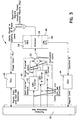
- FIG. 5 a state and action diagram illustrates the load shedding method or power control procedure performed by the terminal control unit 46.
- this block represents the state when all three carrier channels are on (i.e., A, B and C). In this state, as long as the transmit power P T is less than the power threshold P 32 , identified by threshold 66 in Figure 4 (9dB), all three carrier channels will continue to be transmitted. Should the transmit power P T . increase to a level that is equal to or greater than the threshold level P 32 , carrier channel C is turned off and the method progresses to state block 92.
- graph 100 illustrates the power spectral density of five (5) carrier channels, with each carrier channel having two watts of transmit power P T per carrier channel (i.e. a total of 10 watts) and a 10dB backoff from the high power amplifiers saturation level.
- graph 102 the power spectral density of three carrier channels is shown after two carrier channels have been dropped or the transmission terminated. With three carrier channels, ten (10) watt per carrier transmit power P T is available (i.e. a total of 30 watts) with a 5dB backoff from the saturation level of the high power amplifier.
Landscapes
- Engineering & Computer Science (AREA)
- Physics & Mathematics (AREA)
- Astronomy & Astrophysics (AREA)
- Aviation & Aerospace Engineering (AREA)
- General Physics & Mathematics (AREA)
- Computer Networks & Wireless Communication (AREA)
- Signal Processing (AREA)
- Radio Relay Systems (AREA)
- Mobile Radio Communication Systems (AREA)
- Time-Division Multiplex Systems (AREA)
Applications Claiming Priority (2)
| Application Number | Priority Date | Filing Date | Title |
|---|---|---|---|
| US09/275,594 US6272340B1 (en) | 1999-03-24 | 1999-03-24 | Load shedding method to enhance uplink margin with combined FDMA/TDMA uplinks |
| US275594 | 1999-03-24 |
Publications (3)
| Publication Number | Publication Date |
|---|---|
| EP1039659A2 true EP1039659A2 (de) | 2000-09-27 |
| EP1039659A3 EP1039659A3 (de) | 2003-05-21 |
| EP1039659B1 EP1039659B1 (de) | 2005-05-25 |
Family
ID=23053023
Family Applications (1)
| Application Number | Title | Priority Date | Filing Date |
|---|---|---|---|
| EP00105736A Expired - Lifetime EP1039659B1 (de) | 1999-03-24 | 2000-03-17 | Lastverteilungsverfahren zur Besserung des Spielraums kombinierter FDMA/TDMA Aufwärtssignale |
Country Status (6)
| Country | Link |
|---|---|
| US (1) | US6272340B1 (de) |
| EP (1) | EP1039659B1 (de) |
| JP (1) | JP3482174B2 (de) |
| AT (1) | ATE296505T1 (de) |
| CA (1) | CA2301455C (de) |
| DE (1) | DE60020289T2 (de) |
Cited By (1)
| Publication number | Priority date | Publication date | Assignee | Title |
|---|---|---|---|---|
| WO2009066019A1 (fr) * | 2007-09-05 | 2009-05-28 | Eversat | Antenne satellite d'emission et station mobile de telecommunication par satellite |
Families Citing this family (30)
| Publication number | Priority date | Publication date | Assignee | Title |
|---|---|---|---|---|
| US6956840B1 (en) | 1998-09-21 | 2005-10-18 | Ipr Licensing, Inc. | Power control protocol for highly variable data rate reverse link of a wireless communication system |
| US6763006B1 (en) * | 1999-09-22 | 2004-07-13 | Sola Communications, Inc. | Method and apparatus for controlling uplink transmission power within a satellite communication system |
| US6466569B1 (en) * | 1999-09-29 | 2002-10-15 | Trw Inc. | Uplink transmission and reception techniques for a processing satelliteation satellite |
| US6711398B1 (en) * | 2000-04-19 | 2004-03-23 | Hughes Electronics Corporation | Radio signal broadcast system and method |
| US7366463B1 (en) | 2000-05-05 | 2008-04-29 | The Directv Group, Inc. | Military UHF and commercial Geo-mobile system combination for radio signal relay |
| US9485010B1 (en) | 2001-09-10 | 2016-11-01 | The Directv Group, Inc. | Adaptive coding and modulation for spot beam satellite broadcast |
| US7047029B1 (en) | 2001-09-10 | 2006-05-16 | The Directv Group, Inc. | Adaptive transmission system |
| WO2003026189A1 (en) * | 2001-09-20 | 2003-03-27 | Itt Manufacturing Enterprises, Inc. | Methods and apparatus for satellite link throughput adaptation |
| JP2004128993A (ja) * | 2002-10-03 | 2004-04-22 | Ntt Docomo Inc | 送信電力制御方法、基地局、移動局及び無線通信システム |
| KR100524378B1 (ko) * | 2002-11-20 | 2005-10-31 | 한국전자통신연구원 | 다중 빔 위성을 이용한 셀룰러 이동통신시스템에서의적응형 패킷 전송 방법 |
| US7653349B1 (en) | 2003-06-18 | 2010-01-26 | The Directv Group, Inc. | Adaptive return link for two-way satellite communication systems |
| US20050175119A1 (en) * | 2004-02-09 | 2005-08-11 | Worley David A. | Forward link quality link monitoring apparatus and method |
| WO2005112296A2 (en) | 2004-04-29 | 2005-11-24 | Interdigital Technology Corporation | Wireless communication method and system for configuring radio access bearers for enhanced uplink services |
| WO2005115025A2 (en) * | 2004-05-07 | 2005-12-01 | Interdigital Technology Corporation | Wireless communication system and method for configuring cells with enhanced uplink services |
| US7532860B2 (en) * | 2004-09-21 | 2009-05-12 | The Directv Group, Inc. | Method of using feedback from consumer terminals to adaptively control a satellite system |
| US7639981B2 (en) * | 2004-11-02 | 2009-12-29 | Atc Technologies, Llc | Apparatus and methods for power control in satellite communications systems with satellite-linked terrestrial stations |
| US8369800B2 (en) * | 2006-09-15 | 2013-02-05 | Qualcomm Incorporated | Methods and apparatus related to power control and/or interference management in a mixed wireless communications system |
| US8929281B2 (en) * | 2006-09-15 | 2015-01-06 | Qualcomm Incorporated | Methods and apparatus related to peer to peer device |
| US8094606B1 (en) * | 2007-06-15 | 2012-01-10 | Vt Idirect, Inc. | Adjusting transmission power under changing conditions |
| US8480679B2 (en) * | 2008-04-29 | 2013-07-09 | Otismed Corporation | Generation of a computerized bone model representative of a pre-degenerated state and useable in the design and manufacture of arthroplasty devices |
| US8730086B2 (en) * | 2008-08-26 | 2014-05-20 | Viasat, Inc. | Weather detection using satellite communication signals |
| US20100260127A1 (en) * | 2009-04-09 | 2010-10-14 | Eagle River Holdings Llc | System and method for robust transmission in an orthogonal frequency division multiplexed communication system |
| KR20120072037A (ko) * | 2010-12-23 | 2012-07-03 | 한국전자통신연구원 | 다중 스팟빔 위성 시스템에서 빔 대역 할당 장치 및 방법 |
| US9153877B2 (en) * | 2011-12-20 | 2015-10-06 | Space Systems/Loral, Llc | High efficiency multi-beam antenna |
| US8808373B2 (en) * | 2012-06-13 | 2014-08-19 | Elwha Llc | Breast implant with regionalized analyte sensors responsive to external power source |
| US8787144B2 (en) * | 2012-06-29 | 2014-07-22 | Cable Television Laboratories, Inc. | Interleaved signaling |
| US9031559B2 (en) | 2012-11-20 | 2015-05-12 | At&T Mobility Ii Llc | Facilitation of adaptive traffic flow management by a power-limited mobile device |
| US9066300B2 (en) * | 2012-12-07 | 2015-06-23 | At&T Mobility Ii Llc | Dynamic power class re-registration of mobile devices |
| US11688921B1 (en) * | 2021-12-27 | 2023-06-27 | Hughes Network Systems, Llc | Satellite-communications gateway |
| CN116155347B (zh) * | 2022-12-26 | 2024-10-01 | 北京航天控制仪器研究所 | 一种支持多种多址方式的卫星调制解调器 |
Citations (3)
| Publication number | Priority date | Publication date | Assignee | Title |
|---|---|---|---|---|
| EP0805568A1 (de) * | 1996-04-30 | 1997-11-05 | Trw Inc. | Verfahren und Einrichtung zur Leistungssteuerung für ein Satelliten-Telekommunikationssystem |
| EP0837569A2 (de) * | 1996-10-21 | 1998-04-22 | Globalstar L.P. | Fadingdämpfungskontrollanordnung für mehrere Satelliten |
| US5768684A (en) * | 1994-03-04 | 1998-06-16 | Motorola, Inc. | Method and apparatus for bi-directional power control in a digital communication system |
Family Cites Families (1)
| Publication number | Priority date | Publication date | Assignee | Title |
|---|---|---|---|---|
| US5956619A (en) * | 1996-12-12 | 1999-09-21 | Globalstar L.P. | Satellite controlled power control for personal communication user terminals |
-
1999
- 1999-03-24 US US09/275,594 patent/US6272340B1/en not_active Expired - Lifetime
-
2000
- 2000-03-17 AT AT00105736T patent/ATE296505T1/de not_active IP Right Cessation
- 2000-03-17 DE DE60020289T patent/DE60020289T2/de not_active Expired - Lifetime
- 2000-03-17 EP EP00105736A patent/EP1039659B1/de not_active Expired - Lifetime
- 2000-03-21 CA CA002301455A patent/CA2301455C/en not_active Expired - Fee Related
- 2000-03-23 JP JP2000081234A patent/JP3482174B2/ja not_active Expired - Fee Related
Patent Citations (3)
| Publication number | Priority date | Publication date | Assignee | Title |
|---|---|---|---|---|
| US5768684A (en) * | 1994-03-04 | 1998-06-16 | Motorola, Inc. | Method and apparatus for bi-directional power control in a digital communication system |
| EP0805568A1 (de) * | 1996-04-30 | 1997-11-05 | Trw Inc. | Verfahren und Einrichtung zur Leistungssteuerung für ein Satelliten-Telekommunikationssystem |
| EP0837569A2 (de) * | 1996-10-21 | 1998-04-22 | Globalstar L.P. | Fadingdämpfungskontrollanordnung für mehrere Satelliten |
Cited By (2)
| Publication number | Priority date | Publication date | Assignee | Title |
|---|---|---|---|---|
| WO2009066019A1 (fr) * | 2007-09-05 | 2009-05-28 | Eversat | Antenne satellite d'emission et station mobile de telecommunication par satellite |
| CN101816094B (zh) * | 2007-09-05 | 2013-07-17 | 艾维赛特公司 | 卫星传输天线和卫星移动通信站 |
Also Published As
| Publication number | Publication date |
|---|---|
| US6272340B1 (en) | 2001-08-07 |
| DE60020289D1 (de) | 2005-06-30 |
| CA2301455A1 (en) | 2000-09-24 |
| ATE296505T1 (de) | 2005-06-15 |
| JP2000307497A (ja) | 2000-11-02 |
| CA2301455C (en) | 2004-06-01 |
| JP3482174B2 (ja) | 2003-12-22 |
| EP1039659B1 (de) | 2005-05-25 |
| EP1039659A3 (de) | 2003-05-21 |
| DE60020289T2 (de) | 2006-05-04 |
Similar Documents
| Publication | Publication Date | Title |
|---|---|---|
| US6272340B1 (en) | Load shedding method to enhance uplink margin with combined FDMA/TDMA uplinks | |
| US7643441B2 (en) | System and method for adaptive information rate communication | |
| US8131212B2 (en) | Method and apparatus for compensation for weather-based attenuation in a satellite link | |
| EP0911992B1 (de) | Verfahren zur dynamische optimierung der Interferenz für Satelliten die mehreren Antennastrahlen tragen mit gemeinsamen Frequenzen | |
| US8655270B2 (en) | Method and apparatus for compensation for weather-based attenuation in a satellite link | |
| EP0825730B1 (de) | Verfahren und Anordnung zur Sendeleistungssteuerung in einer Aufwärtsverbindung in einer Satellitenkommunikationsanordnung mit hoher Datenrate und An-Bord-De- und Remodulation | |
| US20090296629A1 (en) | Return link power control | |
| EP1168661B1 (de) | Verfahren und Anordnung zur Steuerung der Stärke der Aufwärtssignalen in einem Satelliten Übertragungssystem mit Fehlergleichung | |
| EP2282420A2 (de) | MF-TDMA-Satellitenverbindungsleistungssteuerung | |
| EP1244228A2 (de) | Leistungsregelung in der Aufwärtsverbindung in einem Satelliten Kommunikationssystem | |
| JP2002043996A (ja) | 衛星通信システムの送信パワー・スレッショルドを制御する方法及び装置 | |
| Petranovich | Mitigating the effect of weather on ka-band high-capacity satellites | |
| US6771929B1 (en) | Satellite communication system threshold leveling techniques | |
| Liu et al. | Multi-domain united link adaptation technique in high-throughput satellite communication system | |
| Takahashi et al. | Development of high-data-rate burst modem for WINDS | |
| EP1168663A2 (de) | Umfassende Anordnung und Verfahren für Stärkeregelung einer Aufwärtsverbindung in einem Satelliten Kommunikationssystem | |
| JP2002033692A (ja) | パワーレベル調整を使用する衛星通信システムにおけるアップリンク・パワー制御のためのシステムおよび方法 | |
| Bolea Alamanac et al. | IFMT performance assessment on a point-to-point oriented multimedia broadband communication scenario | |
| Gonzalez et al. | How to evaluate SOTM antennas, modems, and architectures | |
| Hughes et al. | Satellite systems in a VSAT environment | |
| Barnett | Innovations in satellite uplinking | |
| Cornet et al. | Use of fade mitigation techniques for broadcasting and news gathering satellite applications in Ka Band | |
| Besse et al. | On the performance of small aperture Ka-band terminals for use over the Wideband Gapfiller Satellite | |
| Benedicto et al. | AK/Ka-band satellite system providing personal and mobile multimedia telecommunication services | |
| Bennett et al. | Joint IP Modem performance Using WGS |
Legal Events
| Date | Code | Title | Description |
|---|---|---|---|
| PUAI | Public reference made under article 153(3) epc to a published international application that has entered the european phase |
Free format text: ORIGINAL CODE: 0009012 |
|
| AK | Designated contracting states |
Kind code of ref document: A2 Designated state(s): AT BE CH CY DE DK ES FI FR GB GR IE IT LI LU MC NL PT SE |
|
| AX | Request for extension of the european patent |
Free format text: AL;LT;LV;MK;RO;SI |
|
| PUAL | Search report despatched |
Free format text: ORIGINAL CODE: 0009013 |
|
| AK | Designated contracting states |
Designated state(s): AT BE CH CY DE DK ES FI FR GB GR IE IT LI LU MC NL PT SE |
|
| AX | Request for extension of the european patent |
Extension state: AL LT LV MK RO SI |
|
| RAP1 | Party data changed (applicant data changed or rights of an application transferred) |
Owner name: NORTHROP GRUMMAN CORPORATION |
|
| RAP1 | Party data changed (applicant data changed or rights of an application transferred) |
Owner name: NORTHROP GRUMMAN CORPORATION |
|
| 17P | Request for examination filed |
Effective date: 20031121 |
|
| AKX | Designation fees paid |
Designated state(s): AT BE CH CY DE DK ES FI FR GB GR IE IT LI LU MC NL PT SE |
|
| 17Q | First examination report despatched |
Effective date: 20040210 |
|
| GRAP | Despatch of communication of intention to grant a patent |
Free format text: ORIGINAL CODE: EPIDOSNIGR1 |
|
| GRAJ | Information related to disapproval of communication of intention to grant by the applicant or resumption of examination proceedings by the epo deleted |
Free format text: ORIGINAL CODE: EPIDOSDIGR1 |
|
| GRAP | Despatch of communication of intention to grant a patent |
Free format text: ORIGINAL CODE: EPIDOSNIGR1 |
|
| GRAS | Grant fee paid |
Free format text: ORIGINAL CODE: EPIDOSNIGR3 |
|
| GRAA | (expected) grant |
Free format text: ORIGINAL CODE: 0009210 |
|
| AK | Designated contracting states |
Kind code of ref document: B1 Designated state(s): AT BE CH CY DE DK ES FI FR GB GR IE IT LI LU MC NL PT SE |
|
| PG25 | Lapsed in a contracting state [announced via postgrant information from national office to epo] |
Ref country code: LI Free format text: LAPSE BECAUSE OF FAILURE TO SUBMIT A TRANSLATION OF THE DESCRIPTION OR TO PAY THE FEE WITHIN THE PRESCRIBED TIME-LIMIT Effective date: 20050525 Ref country code: CH Free format text: LAPSE BECAUSE OF FAILURE TO SUBMIT A TRANSLATION OF THE DESCRIPTION OR TO PAY THE FEE WITHIN THE PRESCRIBED TIME-LIMIT Effective date: 20050525 Ref country code: AT Free format text: LAPSE BECAUSE OF FAILURE TO SUBMIT A TRANSLATION OF THE DESCRIPTION OR TO PAY THE FEE WITHIN THE PRESCRIBED TIME-LIMIT Effective date: 20050525 Ref country code: FI Free format text: LAPSE BECAUSE OF FAILURE TO SUBMIT A TRANSLATION OF THE DESCRIPTION OR TO PAY THE FEE WITHIN THE PRESCRIBED TIME-LIMIT Effective date: 20050525 Ref country code: NL Free format text: LAPSE BECAUSE OF FAILURE TO SUBMIT A TRANSLATION OF THE DESCRIPTION OR TO PAY THE FEE WITHIN THE PRESCRIBED TIME-LIMIT Effective date: 20050525 Ref country code: BE Free format text: LAPSE BECAUSE OF FAILURE TO SUBMIT A TRANSLATION OF THE DESCRIPTION OR TO PAY THE FEE WITHIN THE PRESCRIBED TIME-LIMIT Effective date: 20050525 |
|
| REG | Reference to a national code |
Ref country code: GB Ref legal event code: FG4D |
|
| REG | Reference to a national code |
Ref country code: CH Ref legal event code: EP |
|
| REG | Reference to a national code |
Ref country code: IE Ref legal event code: FG4D |
|
| REF | Corresponds to: |
Ref document number: 60020289 Country of ref document: DE Date of ref document: 20050630 Kind code of ref document: P |
|
| PG25 | Lapsed in a contracting state [announced via postgrant information from national office to epo] |
Ref country code: DK Free format text: LAPSE BECAUSE OF FAILURE TO SUBMIT A TRANSLATION OF THE DESCRIPTION OR TO PAY THE FEE WITHIN THE PRESCRIBED TIME-LIMIT Effective date: 20050825 Ref country code: GR Free format text: LAPSE BECAUSE OF FAILURE TO SUBMIT A TRANSLATION OF THE DESCRIPTION OR TO PAY THE FEE WITHIN THE PRESCRIBED TIME-LIMIT Effective date: 20050825 Ref country code: SE Free format text: LAPSE BECAUSE OF FAILURE TO SUBMIT A TRANSLATION OF THE DESCRIPTION OR TO PAY THE FEE WITHIN THE PRESCRIBED TIME-LIMIT Effective date: 20050825 |
|
| PG25 | Lapsed in a contracting state [announced via postgrant information from national office to epo] |
Ref country code: PT Free format text: LAPSE BECAUSE OF FAILURE TO SUBMIT A TRANSLATION OF THE DESCRIPTION OR TO PAY THE FEE WITHIN THE PRESCRIBED TIME-LIMIT Effective date: 20051027 |
|
| REG | Reference to a national code |
Ref country code: CH Ref legal event code: PL |
|
| NLV1 | Nl: lapsed or annulled due to failure to fulfill the requirements of art. 29p and 29m of the patents act | ||
| PG25 | Lapsed in a contracting state [announced via postgrant information from national office to epo] |
Ref country code: GB Free format text: LAPSE BECAUSE OF NON-PAYMENT OF DUE FEES Effective date: 20060317 Ref country code: IE Free format text: LAPSE BECAUSE OF NON-PAYMENT OF DUE FEES Effective date: 20060317 |
|
| ET | Fr: translation filed | ||
| PG25 | Lapsed in a contracting state [announced via postgrant information from national office to epo] |
Ref country code: MC Free format text: LAPSE BECAUSE OF NON-PAYMENT OF DUE FEES Effective date: 20060331 Ref country code: LU Free format text: LAPSE BECAUSE OF NON-PAYMENT OF DUE FEES Effective date: 20060331 |
|
| PGFP | Annual fee paid to national office [announced via postgrant information from national office to epo] |
Ref country code: IT Payment date: 20060331 Year of fee payment: 7 |
|
| PLBE | No opposition filed within time limit |
Free format text: ORIGINAL CODE: 0009261 |
|
| STAA | Information on the status of an ep patent application or granted ep patent |
Free format text: STATUS: NO OPPOSITION FILED WITHIN TIME LIMIT |
|
| 26N | No opposition filed |
Effective date: 20060228 |
|
| GBPC | Gb: european patent ceased through non-payment of renewal fee |
Effective date: 20060317 |
|
| REG | Reference to a national code |
Ref country code: IE Ref legal event code: MM4A |
|
| REG | Reference to a national code |
Ref country code: FR Ref legal event code: ST Effective date: 20061130 |
|
| PG25 | Lapsed in a contracting state [announced via postgrant information from national office to epo] |
Ref country code: FR Free format text: LAPSE BECAUSE OF NON-PAYMENT OF DUE FEES Effective date: 20060331 |
|
| PG25 | Lapsed in a contracting state [announced via postgrant information from national office to epo] |
Ref country code: CY Free format text: LAPSE BECAUSE OF FAILURE TO SUBMIT A TRANSLATION OF THE DESCRIPTION OR TO PAY THE FEE WITHIN THE PRESCRIBED TIME-LIMIT Effective date: 20050525 |
|
| PG25 | Lapsed in a contracting state [announced via postgrant information from national office to epo] |
Ref country code: ES Free format text: LAPSE BECAUSE OF NON-PAYMENT OF DUE FEES Effective date: 20060331 |
|
| PG25 | Lapsed in a contracting state [announced via postgrant information from national office to epo] |
Ref country code: IT Free format text: LAPSE BECAUSE OF NON-PAYMENT OF DUE FEES Effective date: 20070317 |
|
| PGFP | Annual fee paid to national office [announced via postgrant information from national office to epo] |
Ref country code: DE Payment date: 20100419 Year of fee payment: 11 |
|
| PG25 | Lapsed in a contracting state [announced via postgrant information from national office to epo] |
Ref country code: DE Free format text: LAPSE BECAUSE OF NON-PAYMENT OF DUE FEES Effective date: 20111001 |
|
| REG | Reference to a national code |
Ref country code: DE Ref legal event code: R119 Ref document number: 60020289 Country of ref document: DE Effective date: 20111001 |
|
| REG | Reference to a national code |
Ref country code: DE Ref legal event code: R082 Ref document number: 60020289 Country of ref document: DE Representative=s name: WUESTHOFF & WUESTHOFF PATENT- UND RECHTSANWAEL, DE |
|
| REG | Reference to a national code |
Ref country code: DE Ref legal event code: R081 Ref document number: 60020289 Country of ref document: DE Owner name: NORTHROP GRUMMAN SYSTEMS CORPORATION, LOS ANGE, US Free format text: FORMER OWNER: NORTHROP GRUMMAN CORP., LOS ANGELES, CALIF., US Effective date: 20120814 Ref country code: DE Ref legal event code: R082 Ref document number: 60020289 Country of ref document: DE Representative=s name: WUESTHOFF & WUESTHOFF, PATENTANWAELTE PARTG MB, DE Effective date: 20120814 Ref country code: DE Ref legal event code: R081 Ref document number: 60020289 Country of ref document: DE Owner name: NORTHROP GRUMMAN SYSTEMS CORPORATION, US Free format text: FORMER OWNER: NORTHROP GRUMMAN CORP., LOS ANGELES, US Effective date: 20120814 Ref country code: DE Ref legal event code: R082 Ref document number: 60020289 Country of ref document: DE Representative=s name: WUESTHOFF & WUESTHOFF PATENT- UND RECHTSANWAEL, DE Effective date: 20120814 |