EP1039338A2 - Cassette for stimulable phosphor sheet, identification means therefor, and image information reading apparatus - Google Patents
Cassette for stimulable phosphor sheet, identification means therefor, and image information reading apparatus Download PDFInfo
- Publication number
- EP1039338A2 EP1039338A2 EP00106337A EP00106337A EP1039338A2 EP 1039338 A2 EP1039338 A2 EP 1039338A2 EP 00106337 A EP00106337 A EP 00106337A EP 00106337 A EP00106337 A EP 00106337A EP 1039338 A2 EP1039338 A2 EP 1039338A2
- Authority
- EP
- European Patent Office
- Prior art keywords
- cassette
- sheet
- stimulable phosphor
- phosphor sheet
- sided
- Prior art date
- Legal status (The legal status is an assumption and is not a legal conclusion. Google has not performed a legal analysis and makes no representation as to the accuracy of the status listed.)
- Withdrawn
Links
Images


Classifications
-
- G—PHYSICS
- G03—PHOTOGRAPHY; CINEMATOGRAPHY; ANALOGOUS TECHNIQUES USING WAVES OTHER THAN OPTICAL WAVES; ELECTROGRAPHY; HOLOGRAPHY
- G03B—APPARATUS OR ARRANGEMENTS FOR TAKING PHOTOGRAPHS OR FOR PROJECTING OR VIEWING THEM; APPARATUS OR ARRANGEMENTS EMPLOYING ANALOGOUS TECHNIQUES USING WAVES OTHER THAN OPTICAL WAVES; ACCESSORIES THEREFOR
- G03B42/00—Obtaining records using waves other than optical waves; Visualisation of such records by using optical means
- G03B42/02—Obtaining records using waves other than optical waves; Visualisation of such records by using optical means using X-rays
- G03B42/04—Holders for X-ray films
Definitions
- the present invention relates to a cassette for housing a stimulable phosphor sheet, the cassette having various items of ID (identification) information, an ID recognition structure for such a cassette for recognizing the ID information when the cassette is loaded into a cassette loading unit, and an image information reading apparatus for reading radiation image information recorded in the stimulable phosphor sheet, thereafter erasing remaining radiation image information from the stimulable phosphor sheet, and returning the stimulable phosphor sheet into a cassette.
- ID identification
- a radiation energy such as X-rays, ⁇ -rays, ⁇ -rays, electron beams, ultraviolet radiation, or the like
- a radiation energy such as X-rays, ⁇ -rays, ⁇ -rays, electron beams, ultraviolet radiation, or the like
- stimulating light such as visible light is subsequently applied to the phosphor, the phosphor emits light depending the stored radiation energy.
- a stimulable phosphor is usually used in the form of a sheet which is referred to as a stimulable phosphor sheet.
- the above known system includes an image information reading apparatus which comprises a reading section for reading image information recorded on a stimulable phosphor sheet, and an erasing section for erasing remaining image information from the stimulable phosphor sheet after the recorded image information has been read.
- an image information reading apparatus which comprises a reading section for reading image information recorded on a stimulable phosphor sheet, and an erasing section for erasing remaining image information from the stimulable phosphor sheet after the recorded image information has been read.
- a cassette housing a stimulable phosphor sheet which bears radiation image information of a subject recorded by an external exposure device is inserted into a loading section.
- the lid of the cassette is opened, and then the stimulable phosphor sheet is taken out of the cassette by a sheet feeding mechanism.
- the stimulable phosphor sheet is delivered to the reading section by a sheet delivering mechanism.
- the reading section the recorded image information is read from the stimulable phosphor sheet, and then remaining image information is erased from the stimulable phosphor sheet in the erasing section, after which the stimulable phosphor sheet is placed into the cassette which has been disposed in the loading section.
- the stimulable phosphor sheet usually comprises an opaque base and a phosphor layer (recording layer) disposed on the opaque base.
- the reading section has a stimulating light applying means for applying stimulating light to the phosphor layer and a light guiding means for collecting light which is emitted from the phosphor layer when the stimulating light is applied to the phosphor layer.
- the erasing section has an erasing light source for applying erasing light to the phosphor layer.
- An image information reading apparatus which is capable of reading image information from the stimulable phosphor sheet with the transparent base has a reading section including two light guiding means that are positioned respectively on the opposite sides of the stimulable phosphor sheet, and an erasing section which applies erasing light to the stimulable phosphor sheet from the side of the phosphor layer.
- a single-sided stimulable phosphor sheet which emits light from the recording layer (phosphor layer)
- a double-sided stimulable phosphor sheet which emits light from the recording layer and the base.
- double-sided stimulable phosphor sheets cannot be recognized in a single image information reading apparatus. Specifically, if a bar code is attached to the base of a double-sided stimulable phosphor sheet, then light applied to read the bar code passes through the base, so that the recording layer is exposed to the light that has passed through the base, and the bar code blocks part of light emitted by the application of stimulating light, resulting in a reading error.
- a main object of the present invention is to provide an ID recognition structure for a cassette for housing a stimulable phosphor sheet, which can reliably recognize ID information of the a stimulable phosphor sheet housed in the cassette when the cassette is loaded into a cassette loading unit.
- Another main object of the present invention is to provide an image information reading apparatus which is capable of reading recorded image information from stimulable phosphor sheets that include single-sided and double-sided stimulable phosphor sheets, is highly versatile, can be manufactured at a low cost, and can be installed in a small space.
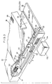
- FIG. 1 shows in perspective a cassette 20 for housing a stimulable phosphor sheet according to a first embodiment of the present invention
- FIG. 2 is a longitudinal cross-sectional view of the cassette 20.
- the cassette 20 comprises a casing 24 for housing a stimulable phosphor sheet 22, and a lid 28 by which an opening 26 in the casing 24 is openably closed.
- the lid 28 supports a first bar code (first ID indicating means) 30 applied to a substantially central portion thereof in its transverse direction, the first bar code 30 representing recorded identification information of the cassette 20.
- a second bar code (second ID indicating means) 34 representing recorded identification information of the cassette 20 is applied to a positioning reference surface 32 of the casing 24 at a forward position thereon in the direction in which the cassette 20 is loaded.
- cassettes 20 of various sets of dimensions depending on the dimensions of the stimulable phosphor sheets 22 housed therein.
- the positioning reference surface 32 on one side of the casing 24 of each cassette 20 is always used as a reference surface.
- cassettes 20 of different sets of dimensions have their positioning reference surfaces 32 placed in the same position at all times when they are loaded into the cassette loading regions 62a through 62d.
- the second bar code 34 is applied to the positioning reference surface 32 at a certain fixed position thereon.
- the stimulable phosphor sheet 22 may be either a single-sided sheet 22a comprising a recording layer (phosphor layer) 38a disposed on an opaque base 36a for emitting light from the recording layer 38a upon exposure to stimulating light, or a double-sided sheet 22b comprising a recording layer (phosphor layer) 38b disposed on a transparent base 36b for emitting light from both surfaces upon exposure to stimulating light.
- the second bar code 34 also represents identification information indicating whether the stimulable phosphor sheet 22 housed in the cassette 20 is the single-sided sheet 22a or the double-sided sheet 22b.
- the single-sided sheet 22a further has a third bar code 39 applied to the base 36a.
- the cassette 20 has a lock means 40 for locking the lid 28 in a closed position on the casing 24.
- the lock means 40 has a slider 44 disposed in the casing 24 and guided by a guide 42 for back-and-forth movement in the directions indicated by the arrow X.
- the slider 44 has a lock tooth 46 and a slanted surface 48 as its integral surfaces.
- the slider 44 is normally urged to move forwardly in the direction indicated by the arrow X1 by a compression spring 50 acting on an end of the slider 44 near the slanted surface 48.
- the lid 28 has a lock hook 52 projecting from an inner surface thereof for locking engagement with the lock finger 46 of the slider 44, and a finger 54 projecting from the inner surface thereof for engagement with the slanted surface 48 to open the lid 28.
- the casing 24 has a pin passage hole 56 defined in a front end wall thereof.
- Each of the cassette loading regions 62a through 62d has an unlock pin 58 fixed in position for being inserted through the pin passage hole 56 to push the slider 44 in the direction indicated by the arrow X2.
- the cassette 20 has inner wall surfaces including a bottom surface 24a facing the recording layer 38 (38a or 38b) of the stimulable phosphor sheet 22 and an upper surface 24b facing the base 36 (36a or 36b) of the stimulable phosphor sheet 22.
- Cushioning members 59a, 59b each in the form of a nonwoven fabric sheet or a fabric sheet are applied respectively to the bottom surface 24a and the upper surface 24b.
- FIG. 4 schematically shows in vertical cross section an image information reading apparatus (loading apparatus) 60 in which the cassette 20 is loaded.
- the image information reading apparatus 60 has an apparatus housing 60a including a front wall (control wall) which supports on its upper portion a touch panel 61 that functions as controls and a display monitor.
- the apparatus housing 60a accommodates therein a plurality of, e.g., four, cassette loading regions 62a through 62d for removably holding respective cassettes 20, disposed below the touch panel 61.
- Each of the cassette loading regions 62a through 62d has a support base 63 for placing the cassette 20 thereon and a shutter 64 openably and closably disposed for blocking light against entry into the apparatus housing 60a.
- a vertical sheet feeder 66 is vertically movably disposed behind the cassette loading regions 62a through 62d.
- the vertical sheet feeder 66 can selectively be aligned with any one of the cassette loading regions 62a through 62d for removing a stimulable phosphor sheet 22 from the cassette 20 in the corresponding one of the cassette loading regions 62a through 62d and returning a stimulable phosphor sheet 22 from which radiation image information is read and erased back into the cassette 20.
- the vertical sheet feeder 66 comprises a sheet feeding mechanism 68 and a lifting and lowering mechanism 70 for vertically moving the sheet feeding mechanism 68 in the vertical directions indicated by the arrow D.
- the lifting and lowering mechanism 70 has a fixed frame 72 with a pair of vertical racks 74a, 74b fixed thereto.
- the lifting and lowering mechanism 70 also has a vertically movable frame 76 to which there is fixed a motor 78 that is operatively coupled to a gear assembly 82 by a belt and pulley means 80.
- the gear assembly 82 serves to transmit rotational forces from the motor 78 to a rotatable shaft 84 which supports on its opposite ends respective pinions 86a, 86b held in mesh with the respective racks 74a, 74b for holding the vertically movable frame 76 in a vertical position.
- the sheet feeding mechanism 68 is incorporated in the vertically movable frame 76.
- the sheet feeding mechanism 68 has a pair of suction cups 90a, 90b movable into the cassette 20 with the lid 28 being open in one of the cassette loading regions 62a through 62d, and a moving means 94 for moving the suction cups 90a, 90b between the cassette 20 and a feeding means 92 for delivering the stimulable phosphor sheet 22 out of the cassette 20 to the feeding means 92 in the direction indicated by the arrow E.
- the vertically movable frame 76 has a pair of side plates 100a, 100b spaced from each other by a certain distance in the direction indicated by the arrow F, which is perpendicular to the direction indicated by the arrow E.
- the moving means 94 has a first motor 102 fixedly mounted on the side plate 100a and having a drive shaft 102a to which a small-diameter pulley 104 is fixed.
- An endless belt 110 is trained around the small-diameter pulley 104 and a large-diameter pulley 108 which is fixed to an end of a drive shaft 106.
- the drive shaft 106 is rotatably supported at its opposite ends on the side plates 100a, 100b.
- An arm 112 has an end secured to the large-diameter pulley 108 and an opposite end to which an end of a link 114 is swingably coupled.
- the link 114 has an opposite end supporting a first pivot shaft 116.
- An end of another arm 112 is secured directly to the other end of the drive shaft 106, and a link 114 with a first pivot shaft 116 is coupled to the other end of the other arm 112.
- the side plates 100a, 100b each have two upper and lower guide grooves 120, 122 for moving the suction cups 90a, 90b along a path inclined obliquely downwardly toward the surface to be attracted of the stimulable phosphor sheet 22, which is opposite to the recording layer thereof.
- the guide grooves 120, 122 are shaped to provide the path for the suction cups 90a, 90b.
- a movable frame 124 has opposite ends to which the first pivot shafts 116 and second pivot shafts 126 are fixed, the first pivot shafts 116 being inserted in the respective guide grooves 120 and the second pivot shafts 126 in the respective guide grooves 122.
- the suction cups 90a, 90b are mounted on the movable frame 124 and spaced from each other by a distance corresponding to the dimension of a smallest stimulable phosphor sheet 22 in the direction indicated by the arrow F.
- the feeding means 92 comprises a plurality of roller pairs 128 and a second motor 130 for rotating the roller pairs 128 in unison with each other.
- All stimulable phosphor sheets 22 of different sets of dimensions that are introduced into the image information reading apparatus 60 are placed in relation to a reference position close to the side plate 100a.
- the reference surfaces 32 of any cassettes 20 that store stimulable phosphor sheets 22 are horizontally spaced a certain distance from the side plate 100a at all times.
- On the side plate 100a there is mounted a reading means 132 for reading the second bar code 34, in horizontal alignment with the second bar code 34 on the reference surface 32 of the cassette 20 placed in any one of the cassette loading regions 62a through 62d which is being operated upon by the vertical sheet feeder 66.
- the second bar code 34 and the reading means 132 jointly make up an ID recognition structure (sheet identifying assembly) 134. Since the second bar code 34 is used as an identification medium, the reading means 132 comprises a bar-code reader.
- the image information reading apparatus 60 also has an erasure unit 138 and a reading unit 140 which are disposed in the apparatus housing 60a below the vertical sheet feeder 66 and connected to the vertical sheet feeder 66 through a feed system 136.
- the feed system 136 comprises a plurality of roller pairs 142 which jointly make up a vertical feed path extending downwardly from the vertical sheet feeder 66 and a horizontal feed path extending horizontally from the lower end of the vertical feed path.
- a bar-code reader 141 is positioned near the lower end of the vertical feed path for reading the third bar code 39 applied to the single-sided stimulable phosphor sheet 22a.
- the reading unit 140 is disposed above the horizontal feed path.
- the reading unit 140 comprises an auxiliary scanning feeding mechanism 144 for delivering a stimulable phosphor sheet 22 from a cassette 20 in an auxiliary scanning direction indicated by the arrow A, an optical system 146 for applying a laser beam L as it is deflected in a main scanning direction (substantially perpendicular to the auxiliary scanning direction) to the stimulable phosphor sheet 22 as it is delivered in the auxiliary canning direction, and first and second light guiding systems (light guiding means) 148a, 148b for photoelectrically reading light which is emitted from the stimulable phosphor sheet 22 when the stimulable phosphor sheet 22 is exposed to the laser beam L.
- first and second light guiding systems (light guiding means) 148a, 148b for photoelectrically reading light which is emitted from the stimulable phosphor sheet 22 when the stimulable phosphor sheet 22 is exposed to the laser beam L.
- the auxiliary scanning feeding mechanism 144 has first and second roller pairs 150, 152 rotatable in synchronism with each other. Each of the first and second roller pairs 150, 152 has a pair of rollers that can be moved toward and away from each other.
- the first light guiding system 148a comprises a first light guide 154a extending along a main scanning line on the recording layer of the stimulable phosphor sheet 22 where the laser beam L is applied, and a first photomultiplier 156a mounted on an upper end of the first light guide 154a.
- the second light guiding system 148b which is disposed on the reverse side of the stimulable phosphor sheet 22, comprises a second light guide 154b extending along a main scanning line on the reverse side of the stimulable phosphor sheet 22, and a second photomultiplier 156b mounted on an end of the second light guide 154b.
- a sheet feeder 158 for upwardly feeding the stimulable phosphor sheet 22 from which radiation image information has been read by the reading unit 140 is disposed downstream of the reading unit 140 in the direction of travel of the stimulable phosphor sheet 22 through the reading unit 140.
- the leading end of the stimulable phosphor sheet 22 is guided horizontally over a power supply 160 above the erasure unit 138 via an erasing unit feeder 162 disposed near the power supply 160.
- the erasing unit feeder 162 then feeds back the stimulable phosphor sheet 22, whose leading end has been fed over the power supply 162, horizontally from the left to the right into the erasure unit 138.
- the erasure unit 138 comprises a first erasing unit 164a disposed on one side of the feed path of the erasing unit feeder 162, i.e., on the side of the recording layer 38 of the stimulable phosphor sheet 22, and a second erasing unit 164b disposed on the other side of the feed path of the erasing unit feeder 162, i.e., on the side of the base 36 (reverse side) of the stimulable phosphor sheet 22.
- the first and second erasing units 164a, 164b comprise respective horizontal arrays of erasing light sources 166a, 166b.
- the erasing unit feeder 162 extends horizontally through the erasure unit 138 and then upwardly obliquely, and is connected to the feed system 136.
- a controller (control means) 168 is disposed in an upper end portion of the apparatus housing 60a, for controlling the image information reading apparatus 60 in its entirety.
- the controller 168 is supplied with an identification signal (cassette identification signal) from the reading means 132 of the ID recognition structure 134, and functions to search for (cite) pre-registered patient information, recording information, etc., determine whether the stimulable phosphor sheet 22 in a cassette 20 is a single-sided sheet 22a or a double-sided sheet 22b, and control the turning on/off of the second light guiding system 148b and the second erasing unit 164b.
- an identification signal cassette identification signal
- a cassette 20 which stores a stimulable phosphor sheet 22 which carries radiation image information of a subject such as a human body recorded by an exposure device (not shown) is introduced into the apparatus housing 60a along the support base 63 of the cassette loading region 62a, for example.
- the leading end of the cassette 20 pushes open the shutter 64, and enters the interior space of the apparatus housing 60a.
- the first bar code 30 applied to the cassette 20 is used when the user registers ID information.
- the unlock pin 58 passes through the pin passage hole 56 in the casing 24 and pushes the slider 44 relatively in the direction indicated by the arrow X2.
- the slider 44 moves in the direction indicated by the arrow X2, causing the lock tooth 46 to disengage from the lock hook 52 of the lid 28 for thereby unlocking the lid 28.
- the slanted surface 48 of the slider 44 slidingly engages the finger 54 of the lid 28, opening the lid 28 to a certain angular position.
- the lifting and lowering mechanism 70 of the vertical sheet feeder 66 is operated to lift or lower the sheet feeding mechanism 68 into horizontal alignment with the cassette loading region 62a, for example. More specifically, as shown in FIG. 5, the motor 78 mounted on the vertically movable frame 76 is energized to cause the belt and pulley means 80 and the gear assembly 82 to rotate the rotatable shaft 84 about its own axis in one direction.
- the pinions 86a, 86b mounted on the respective opposite ends of the rotatable shaft 84 in mesh with the racks 74a, 74b move in one of the directions indicated by the arrow D, i.e., either upwardly or downwardly; to bring the sheet feeding mechanism 68 mounted on the vertically movable frame 76 into horizontal alignment with the cassette loading region 62a.
- the side plate 100a that moves vertically in unison with the vertically movable frame 76 is horizontally aligned with the cassette loading region 62a, and the reading means 132 mounted on the side plate 100a is positioned in horizontal alignment with the second bar code 34 applied to the reference surface 32 of the cassette 20 loaded in the cassette loading region 62a.
- the controller 168 determines whether the stimulable phosphor sheet 22 in the cassette 20 is a single-sided sheet 22a or a double-sided sheet 22b, and searches for patient information, recording information, etc. from the read bar-code number.
- the controller 168 turns off the second light guiding system 148b of the reading unit 140 and the second erasing unit 164b of the erasure unit 138.
- the moving means 94 is actuated to displace the suction cups 90a, 90b into the cassette 20.
- the small-diameter pulley 104 is rotated to cause the belt 110 to rotate the large-diameter pulley 108 and the drive shaft 106 in unison with each other in one direction.
- the arms 112 fixed to the large-diameter pulley 108 and the opposite end of the drive shaft 106 are angularly moved about the axis of the drive shaft 106.
- first and second pivot shafts 116, 126 move along the guide grooves 120, 122.
- the movable frame 124 displaces the suction cups 90a, 90b along the path inclined obliquely downwardly toward the base 36a of the single-sided stimulable phosphor sheet 22a in the cassette 20.
- the guide plate 127 mounted on the movable frame 124 enters the cassette 20 for further angularly moving the lid 28 to an angular position to allow the suction cups 90a, 90b to find their way into the cassette 20.
- the suction cups 90a, 90b attract and hold the base 36a of the single-sided sheet 22a, and the first motor 102 of the moving means 94 is reversed to turn the arms 112 to move the suction cups 90a, 90b in unison with the movable frame 124 from the cassette 20 toward the feeding means 92.
- the single-sided sheet 22a attracted by the suction cups 90a, 90b is now removed from the cassette 20 through the opening 26 thereof.
- the leading end of the single-sided sheet 22a is then gripped by the roller pairs 128 of the feeding means 92. Since the roller pairs 128 have been rotated at a certain speed by the second motor 130, the single-sided sheet 22a is released from the suction cups 90a, 90b substantially at the same time that the leading end of the single-sided sheet 22a is gripped by the roller pairs 128. The single-sided sheet 22a is transferred from the roller pairs 128 to the feed system 136, and then fed downwardly by the roller pairs 142 of the feed system 136.
- the third bar code 39 applied to the base 36a of the single-sided sheet 22a passes across the bar-code reader 141, the third bar code 39 is read by the bar-code reader 141. After the patient information, recording information, etc. corresponding to the single-sided sheet 22a is searched for, the single-sided sheet 22a is sent to the reading unit 140.
- the laser beam L emitted from the optical system 146 is applied to the recording layer 38a of the single-sided sheet 22a. Radiation image information stored in the single-sided sheet 22a is now photoelectrically read by the first light guiding system 148a.
- the single-sided sheet 22a is fed vertically upwardly by the sheet feeder 158, and transferred from the sheet feeder 158 to the erasing unit feeder 162 with the leading end being guided horizontally above the power supply 160.
- the single-sided sheet 22a is fed horizontally with its trailing end as fed by the sheet feeder 158 serving as the leading end.
- the first erasing unit 164a of the erasure unit 138 erases remaining radiation image information from the single-sided sheet 22a with the erasing light sources 166a.
- the single-sided sheet 22a is fed to the feed system 136, and then fed upwardly by the feed system 136, after which the single-sided sheet 22a is sent back into the empty cassette 20 in the cassette loading region 62a by the vertical sheet feeder 66.
- the vertical sheet feeder 66 moves vertically to a position for removing the stimulable phosphor sheet 22 from the cassette 20 that is loaded in the cassette loading region 62b, for example. Therefore, a plurality of stimulable phosphor sheets 22 are simultaneously processed differently in the apparatus housing 60a.
- the controller 168 turns on the first and second light guiding systems 148a, 148b and also turns on the erasing light sources 166a, 166b of the respective first and second erasing units 164a, 164b.
- the controller 168 turns off the bar-code reader 141.
- the double-sided sheet 22b is removed from the cassette 20 and delivered to the feed system 136 by the sheet feeding mechanism 68, the double-sided sheet 22b is fed to the reading unit 140 by the roller pairs 142 of the feed system 136.
- the laser beam L emitted from the optical system 146 is applied to the recording layer 38b of the double-sided sheet 22b.
- the double-sided sheet 22b is switched back by the erasing unit feeder 162, and fed horizontally between the first and second erasing units 164a, 164b of the erasure unit 138.
- the erasing light sources 166a, 166b of the first and second erasing units 164a, 164b apply erasing light to the both surfaces of the double-sided sheet 22b thereby to remove remaining radiation image information from the double-sided sheet 22b.
- the double-sided sheet 22b is fed to the feed system 136, and then fed upwardly by the feed system 136, after which the double-sided sheet 22b is sent back into the empty cassette 20 in the cassette loading region 62b by the vertical sheet feeder 66.
- the second bar code 34 as an identification medium is applied to the reference surface 32 of the cassette 20, and the reading means 132 for reading the second bar code 34 is incorporated in the vertical sheet feeder 66. Therefore, the image information reading apparatus 60 is capable of reliably recognizing whether the stimulable phosphor sheet 22 in the cassette 20 is a single-sided sheet 22a or a double-sided sheet 22b. If the stimulable phosphor sheet 22 is recognized as a single-sided sheet 22a, then the second light guiding system 148b and the second erasing unit 164b are tuned off. If the stimulable phosphor sheet 22 is recognized as a double-sided sheet 22b, then the second light guiding system 148b and the second erasing unit 164b are turned on and the bar-code reader 141 is turned off.
- the image information reading apparatus 60 is capable of reliably distinguishing between a double-sided sheet 22b to which bar codes cannot directly be applied and a single-sided sheet 22a which is usually used, and well reading radiation image information from those single-sided and double-sided sheets 22a, 22b.
- the second bar code 34 as a second ID indicating means is applied to the reference surface 32 which is used for positioning the cassette 20 when it is loaded.
- the second bar codes 34 applied to the reference surfaces 32 of the cassettes 20 are located in a constant position at all times, i.e., in a position that can be aligned with the reading means 132. Consequently, ID information corresponding to stimulable phosphor sheets 22 housed in variously dimensioned cassettes 20 can reliably be searched for.
- the first bar code 30 is applied to the substantially central portion of the lid 28 in its transverse direction cannot. If the cassette 20 has different dimensions, then since the position of the first bar code 30 from the reference surface 32 differs, the first bar code 30 cannot accurately be read in the image information reading apparatus 60. Therefore, the first bar code 30 is normally used when the user registers ID information.
- the cushioning members 59a, 59b each in the form of a nonwoven fabric sheet or a fabric sheet are applied respectively to the bottom surface 24a and the upper surface 24b which are contacted by the recording layer 38 and the base 36, respectively, of the stimulable phosphor sheet 22. Therefore, the recording layer 38 and the base 36 of the stimulable phosphor sheet 22 in the cassette 20 are prevented from being damaged by the cassette 20, and hence no worn-off particles are produced and carried into the image information reading apparatus 60.
- the cushioning member 59b for protecting the base 36b is effective to prevent the base 36b from being damaged as much as possible.
- the same image information reading apparatus 60 is capable of effectively processing both a single-sided sheet 22a and a double-sided sheet 22b which have heretofore been processed to read recorded radiation image information by two dedicated image information reading apparatus.
- the image information reading apparatus 60 operates as a shared machine, the equipment cost and the installation space can greatly be reduced.
- Single-sided sheets 22a are used for recording radiation image information of ordinary subjects
- double-sided sheets 22b are used for recording radiation image information of subjects which require a high image quality level, e.g., according to mammography, for example. Because these different types of stimulable phosphor sheets 22 can be processed by the same image information reading apparatus 60, the versatility of the image information reading apparatus 60 is highly increased.
- the second bar code 34 is applied to all cassettes 20 and represents information for distinguishing between a single-sided sheet 22a and a double-sided sheet 22b.
- the second bar code 34 may be applied to only those cassettes 20 which store double-sided sheets 22b.
- the reading means 132 detects the second bar code 34 on a cassette 20
- the reading means 132 does not detect the second bar code 34 on a cassette 20
- the third bar code 39 is applied to the base 36a of a single-sided sheet 22a, then the third bar code 39 is read by the bar-code reader 141, so that ID information of the single-sided sheet 22a can reliably be obtained.
- the ID recognition structure (sheet identifying assembly) 134 may comprise a thickness detecting means associated with either one of the roller pairs 142 of the feed system 136, and the single-sided sheet 22a and the double-sided sheet 22b may have different thicknesses.
- the thickness detecting means detects the difference between the thicknesses of the single-sided sheet 22a and the double-sided sheet 22b, it is possible to distinguish reliably between the single-sided sheet 22a and the double-sided sheet 22b, so that radiation image information can be read from the single-sided sheet 22a and the double-sided sheet 22b efficiently and highly accurately in a manner suitable for those different types of sheets.
- the first erasing unit 164a is positioned on the side of the recording layer of the stimulable phosphor sheet 22, and the second erasing unit 164b is positioned on the reverse side of the stimulable phosphor sheet 22.
- the first erasing unit 164a may be used to erase remaining radiation image information from the stimulable phosphor sheet 22.
- FIG. 7 shows in perspective a cassette 180 for housing a stimulable phosphor sheet according to a second embodiment of the present invention.
- Those parts of the cassette 180 which are identical to those of the cassette 20 according to the first embodiment are denoted by identical reference characters, and will not be described in detail below.
- the cassette 180 has, in addition to the first bar code 30, a second bar code 34a applied to the lid 28 at a position spaced a certain distance from the reference surface 32 in the transverse direction of the cassette 180.
- the second bar code 34a is always located at a constant position spaced from the reference surface 32. The distance between the reference surface 32 and the second bar code 34a remains constant on various cassettes 20 having different sets of dimensions.
- the apparatus housing 60a has a reading means (not shown) for reading the second bar code 34a, the reading means comprising a bar-code reader mounted on the sheet feeding mechanism 68.
- the non-illustrated reading means reads the second bar code 34a on the lid 28 to determine whether the stimulable phosphor sheet 22 is a single-sided sheet 22a or a double-sided sheet 22b. Accordingly, a process of distinguishing between a single-sided sheet 22a and a double-sided sheet 22b can reliably be performed by a relatively simple arrangement, as with the first embodiment.
- FIG. 8 schematically shows an image information reading apparatus (loading apparatus) 200 which incorporates an ID recognition structure (sheet identifying assembly) 190 according to a third embodiment of the present invention.
- ID recognition structure 190 and the image information reading apparatus 200 which are identical to those of the ID recognition structure 134 and the image information reading apparatus 60 according to the first embodiment are denoted by identical reference characters, and will not be described in detail below.
- the image information reading apparatus 200 has an apparatus housing 202 which accommodates a cassette loading region 204 for loading a single cassette 20 in a front wall (control wall) of the apparatus housing 202.
- the cassette loading region 204 includes a reading means 206 for reading the second bar code 34 applied to the reference surface 32 of the cassette 20, the reading means 206 being horizontally aligned with the second bar code 34.
- the reading means 206 and the second bar code 34 jointly make up an ID recognition structure 190.
- the second bar code 34 on the cassette 20 is positioned in horizontal alignment with the reading means 206, which determines whether a single-sided sheet 22a or a double-sided sheet 22b is housed in the cassette 20. Therefore, the reading unit 140 is able to well read recorded radiation image information from both a single-sided sheet 22a and a double-sided sheet 22b, and the erasure unit 138 is capable of reliably erasing remaining radiation image information from the single-sided sheet 22a and the double-sided sheet 22b.
- the single image information reading apparatus 200 can thus reliably process the single-sided sheet 22a and the double-sided sheet 22b as desired.
- the single image information reading apparatus 200 is therefore highly versatile, and requires a reduced equipment cost and a reduced installation space, as with the first embodiment.
- FIG. 9 schematically shows an image information reading apparatus (loading apparatus) 300 according to a fourth embodiment of the present invention.
- Those parts of the image information reading apparatus 300 which are identical to those of the image information reading apparatus 200 according to the second embodiment are denoted by identical reference characters, and will not be described in detail below.
- the cassette loading region 204 has a reading means 306 aligned with a sheet magnet 304 as an identification medium applied to a cassette 302 which houses a double-sided sheet 22b. Further, the cassette loading region 204 has the reading means 206 aligned with the second bar code 34. The reading means 306 and the sheet magnet 304 jointly make up a sheet identifying assembly 308.
- the cassette 302 comprises a casing 310 for housing a double-sided sheet 22b, and a lid 314 by which an opening 312 in the casing 310 is openably closed.
- the casing 310 supports the sheet magnet 304 on a leading end thereof in the direction in which the cassette 302 is loaded, the sheet magnet 304 being embedded so as to lie substantially flush with the reverse side of the casing 310.
- the sheet magnet 304 is positioned adjacent to the second bar code 34 applied to a positioning reference surface 316 of the casing 310.
- the reading means 306 is positioned in vertical alignment with the sheet magnet 304 when the cassette 302 is loaded in the cassette loading region 204.
- the reading means 306 comprises a magnet sensor for magnetically detecting whether there is the sheet magnet 304 or not.
- the sheet magnet 304 embedded in the casing 310 of the cassette 302 is positioned in vertical alignment with the reading means 306, which detects the sheet magnet 304. Therefore, it is possible to determine that the double-sided sheet 22b is housed in the cassette 302.
- the reading means 206 reads the second bar code 34 so as to obtain ID information such as patient information and recording information, etc.
- the reading means 306 When a cassette 18 housing a single-sided sheet 22a is loaded into the cassette loading region 204, the reading means 306 does not detect any sheet magnet, and determines that the single-sided sheet 22a is housed in the cassette 302.
- the fourth embodiment therefore, it is possible to reliably determine which of the single-sided sheet 22a and the double-sided sheet 22b is loaded in the apparatus housing 202.
- the single image information reading apparatus 300 can thus reliably process the single-sided sheet 22a and the double-sided sheet 22b as desired, as with the first and second embodiments.
- the sheet magnet 304 may be applied to the reference surface 316 of the casing 310 of the cassette 302, and the reading means 306 may be positioned in horizontal alignment with the reference surface 316, with the sheet magnet 304 being positioned on the leading end of the casing 310 in the direction in which it is inserted into the cassette loading region 204.
- the ID recognition structure 308 may be incorporated in the image information reading apparatus 10 according to the first embodiment. While the sheet magnet 304 is attached to the cassette 302 housing the double-sided sheet 22b in the illustrated fourth embodiment, the sheet magnet 304 may be attached to a cassette housing a single-sided sheet 22a.
- the cassette has on its outer surface the first ID indicating means which is used when the user registers ID information and the second ID indicating means for reading ID information with the loading apparatus in which the cassette is loaded. Therefore, various items of information relative to the stimulable phosphor sheet housed in the cassette can reliably be read. Even though a bar code or the like cannot directly be applied to a double-sided sheet having a transparent base, ID information of the double-sided sheet can be read through the second ID indicating means that is attached to the cassette that houses the double-sided sheet. Consequently, various stimulable phosphor sheets can efficiently be processed by the image information reading apparatus.
- the single image information reading apparatus is capable of well processing both a single-sided sheet and a double-sided sheet
- the image information reading apparatus can effectively be used as a shared machine for greatly increased versatility.
- the single image information reading apparatus is highly economical because its equipment cost and installation space is much smaller than if two image information reading apparatus dedicated respectively to single-sided sheets and double-sided sheets were employed.
Abstract
Description
- The present invention relates to a cassette for housing a stimulable phosphor sheet, the cassette having various items of ID (identification) information, an ID recognition structure for such a cassette for recognizing the ID information when the cassette is loaded into a cassette loading unit, and an image information reading apparatus for reading radiation image information recorded in the stimulable phosphor sheet, thereafter erasing remaining radiation image information from the stimulable phosphor sheet, and returning the stimulable phosphor sheet into a cassette.
- There is known a system for recording radiation image information of a subject such as a human body with a stimulable phosphor, and reproducing the recorded radiation image information on a photosensitive medium such as a photographic film, or displaying the recorded radiation image information on a display device such as a CRT or the like.
- When a radiation energy such as X-rays, α-rays, γ-rays, electron beams, ultraviolet radiation, or the like is applied to a certain phosphor, it stores part of the applied radiation energy. Then stimulating light such as visible light is subsequently applied to the phosphor, the phosphor emits light depending the stored radiation energy. Such a phosphor is referred to as a stimulable phosphor. A stimulable phosphor is usually used in the form of a sheet which is referred to as a stimulable phosphor sheet.
- The above known system includes an image information reading apparatus which comprises a reading section for reading image information recorded on a stimulable phosphor sheet, and an erasing section for erasing remaining image information from the stimulable phosphor sheet after the recorded image information has been read. In the image information reading apparatus, a cassette housing a stimulable phosphor sheet which bears radiation image information of a subject recorded by an external exposure device is inserted into a loading section.
- Thereafter, the lid of the cassette is opened, and then the stimulable phosphor sheet is taken out of the cassette by a sheet feeding mechanism. The stimulable phosphor sheet is delivered to the reading section by a sheet delivering mechanism. In the reading section, the recorded image information is read from the stimulable phosphor sheet, and then remaining image information is erased from the stimulable phosphor sheet in the erasing section, after which the stimulable phosphor sheet is placed into the cassette which has been disposed in the loading section.
- The stimulable phosphor sheet usually comprises an opaque base and a phosphor layer (recording layer) disposed on the opaque base. The reading section has a stimulating light applying means for applying stimulating light to the phosphor layer and a light guiding means for collecting light which is emitted from the phosphor layer when the stimulating light is applied to the phosphor layer. The erasing section has an erasing light source for applying erasing light to the phosphor layer.
- There has recently been a demand for the efficient reading of energy stored in stimulable phosphor sheets in order to reproduce the radiation image information of subjects with high image quality in various applications such as mammography. One effort that has been made to meet the demand is to employ a stimulable phosphor sheet having a transparent base. When stimulating light is applied to the stimulable phosphor sheet with the transparent base from the side of the phosphor layer, the stimulable phosphor sheet emits light from the side of the base (reverse side) as well as from the side of the phosphor layer. An image information reading apparatus which is capable of reading image information from the stimulable phosphor sheet with the transparent base has a reading section including two light guiding means that are positioned respectively on the opposite sides of the stimulable phosphor sheet, and an erasing section which applies erasing light to the stimulable phosphor sheet from the side of the phosphor layer.
- As described above, there are two types of stimulable phosphor sheets, i.e., a single-sided stimulable phosphor sheet which emits light from the recording layer (phosphor layer), and a double-sided stimulable phosphor sheet which emits light from the recording layer and the base. It has been pointed out that double-sided stimulable phosphor sheets cannot be recognized in a single image information reading apparatus. Specifically, if a bar code is attached to the base of a double-sided stimulable phosphor sheet, then light applied to read the bar code passes through the base, so that the recording layer is exposed to the light that has passed through the base, and the bar code blocks part of light emitted by the application of stimulating light, resulting in a reading error. Therefore, using both single-sided and double-sided stimulable phosphor sheets together requires two image information reading apparatus dedicated respectively for the single-sided stimulable phosphor sheets and the double-sided stimulable phosphor sheets. Those two image information reading apparatus result in a higher equipment cost and a greater installation space.
- It is a general object of the present invention to provide a cassette for housing a stimulable phosphor sheet, which can reliably indicate ID information of the stimulable phosphor sheet housed therein and which is highly versatile.
- A main object of the present invention is to provide an ID recognition structure for a cassette for housing a stimulable phosphor sheet, which can reliably recognize ID information of the a stimulable phosphor sheet housed in the cassette when the cassette is loaded into a cassette loading unit.
- Another main object of the present invention is to provide an image information reading apparatus which is capable of reading recorded image information from stimulable phosphor sheets that include single-sided and double-sided stimulable phosphor sheets, is highly versatile, can be manufactured at a low cost, and can be installed in a small space.
- The above and other objects, features, and advantages of the present invention will become more apparent from the following description when taken in conjunction with the accompanying drawings in which preferred embodiments of the present invention are shown by way of illustrative example.
-
- FIG. 1 is a perspective view of a cassette for housing a stimulable phosphor sheet according to a first embodiment of the present invention;
- FIG. 2 is a longitudinal cross-sectional view of the cassette;
- FIG. 3 is a fragmentary perspective view of a lock means of the cassette;
- FIG. 4 is a schematic vertical cross-sectional view of an image information reading apparatus which incorporates an ID recognition structure according to the first embodiment of the present invention;
- FIG. 5 is a fragmentary perspective view of a vertical sheet feeder of the image information reading apparatus;
- FIG. 6 is a fragmentary side elevational view of a sheet feeding mechanism of the image information reading apparatus;
- FIG. 7 is a perspective view of a cassette for housing a stimulable phosphor sheet according to a second embodiment of the present invention;
- FIG. 8 is a schematic vertical cross-sectional view of an image information reading apparatus which incorporates an ID recognition structure according to a third embodiment of the present invention;
- FIG. 9 is a schematic vertical cross-sectional view of an image information reading apparatus according to a fourth embodiment of the present invention; and
- FIG. 10 is a perspective view of a cassette having a sheet magnet attached to a bottom thereof.
-
- FIG. 1 shows in perspective a
cassette 20 for housing a stimulable phosphor sheet according to a first embodiment of the present invention, and FIG. 2 is a longitudinal cross-sectional view of thecassette 20. - As shown in FIGS. 1 and 2, the
cassette 20 comprises acasing 24 for housing astimulable phosphor sheet 22, and alid 28 by which an opening 26 in thecasing 24 is openably closed. Thelid 28 supports a first bar code (first ID indicating means) 30 applied to a substantially central portion thereof in its transverse direction, thefirst bar code 30 representing recorded identification information of thecassette 20. A second bar code (second ID indicating means) 34 representing recorded identification information of thecassette 20 is applied to apositioning reference surface 32 of thecasing 24 at a forward position thereon in the direction in which thecassette 20 is loaded. - There are
cassettes 20 of various sets of dimensions depending on the dimensions of thestimulable phosphor sheets 22 housed therein. Whencassettes 20 are loaded into respectivecassette loading regions 62a through 62d (described later on), thepositioning reference surface 32 on one side of thecasing 24 of eachcassette 20 is always used as a reference surface. Specifically,cassettes 20 of different sets of dimensions have theirpositioning reference surfaces 32 placed in the same position at all times when they are loaded into thecassette loading regions 62a through 62d. Thesecond bar code 34 is applied to thepositioning reference surface 32 at a certain fixed position thereon. - The
stimulable phosphor sheet 22 may be either a single-sided sheet 22a comprising a recording layer (phosphor layer) 38a disposed on anopaque base 36a for emitting light from therecording layer 38a upon exposure to stimulating light, or a double-sided sheet 22b comprising a recording layer (phosphor layer) 38b disposed on atransparent base 36b for emitting light from both surfaces upon exposure to stimulating light. Thesecond bar code 34 also represents identification information indicating whether thestimulable phosphor sheet 22 housed in thecassette 20 is the single-sided sheet 22a or the double-sided sheet 22b. The single-sided sheet 22a further has athird bar code 39 applied to thebase 36a. - As shown in FIG. 3, the
cassette 20 has a lock means 40 for locking thelid 28 in a closed position on thecasing 24. The lock means 40 has aslider 44 disposed in thecasing 24 and guided by aguide 42 for back-and-forth movement in the directions indicated by the arrow X. Theslider 44 has alock tooth 46 and aslanted surface 48 as its integral surfaces. Theslider 44 is normally urged to move forwardly in the direction indicated by the arrow X1 by acompression spring 50 acting on an end of theslider 44 near theslanted surface 48. Thelid 28 has alock hook 52 projecting from an inner surface thereof for locking engagement with thelock finger 46 of theslider 44, and afinger 54 projecting from the inner surface thereof for engagement with theslanted surface 48 to open thelid 28. Thecasing 24 has apin passage hole 56 defined in a front end wall thereof. Each of thecassette loading regions 62a through 62d has anunlock pin 58 fixed in position for being inserted through thepin passage hole 56 to push theslider 44 in the direction indicated by the arrow X2. - As shown in FIG. 2, the
cassette 20 has inner wall surfaces including abottom surface 24a facing the recording layer 38 (38a or 38b) of thestimulable phosphor sheet 22 and an upper surface 24b facing the base 36 (36a or 36b) of thestimulable phosphor sheet 22.Cushioning members bottom surface 24a and the upper surface 24b. - FIG. 4 schematically shows in vertical cross section an image information reading apparatus (loading apparatus) 60 in which the
cassette 20 is loaded. - The image
information reading apparatus 60 has anapparatus housing 60a including a front wall (control wall) which supports on its upper portion atouch panel 61 that functions as controls and a display monitor. Theapparatus housing 60a accommodates therein a plurality of, e.g., four,cassette loading regions 62a through 62d for removably holdingrespective cassettes 20, disposed below thetouch panel 61. Each of thecassette loading regions 62a through 62d has asupport base 63 for placing thecassette 20 thereon and ashutter 64 openably and closably disposed for blocking light against entry into theapparatus housing 60a. Avertical sheet feeder 66 is vertically movably disposed behind thecassette loading regions 62a through 62d. Thevertical sheet feeder 66 can selectively be aligned with any one of thecassette loading regions 62a through 62d for removing astimulable phosphor sheet 22 from thecassette 20 in the corresponding one of thecassette loading regions 62a through 62d and returning astimulable phosphor sheet 22 from which radiation image information is read and erased back into thecassette 20. - As shown in FIG. 5, the
vertical sheet feeder 66 comprises asheet feeding mechanism 68 and a lifting and loweringmechanism 70 for vertically moving thesheet feeding mechanism 68 in the vertical directions indicated by the arrow D. The lifting and loweringmechanism 70 has a fixedframe 72 with a pair ofvertical racks mechanism 70 also has a verticallymovable frame 76 to which there is fixed amotor 78 that is operatively coupled to agear assembly 82 by a belt and pulley means 80. Thegear assembly 82 serves to transmit rotational forces from themotor 78 to arotatable shaft 84 which supports on its opposite endsrespective pinions respective racks movable frame 76 in a vertical position. Thesheet feeding mechanism 68 is incorporated in the verticallymovable frame 76. - The
sheet feeding mechanism 68 has a pair ofsuction cups cassette 20 with thelid 28 being open in one of thecassette loading regions 62a through 62d, and a moving means 94 for moving thesuction cups cassette 20 and a feeding means 92 for delivering thestimulable phosphor sheet 22 out of thecassette 20 to the feeding means 92 in the direction indicated by the arrow E. - The vertically
movable frame 76 has a pair ofside plates means 94 has afirst motor 102 fixedly mounted on theside plate 100a and having adrive shaft 102a to which a small-diameter pulley 104 is fixed. Anendless belt 110 is trained around the small-diameter pulley 104 and a large-diameter pulley 108 which is fixed to an end of adrive shaft 106. - The
drive shaft 106 is rotatably supported at its opposite ends on theside plates arm 112 has an end secured to the large-diameter pulley 108 and an opposite end to which an end of alink 114 is swingably coupled. Thelink 114 has an opposite end supporting afirst pivot shaft 116. An end of anotherarm 112 is secured directly to the other end of thedrive shaft 106, and alink 114 with afirst pivot shaft 116 is coupled to the other end of theother arm 112. - The
side plates lower guide grooves suction cups stimulable phosphor sheet 22, which is opposite to the recording layer thereof. Theguide grooves suction cups movable frame 124 has opposite ends to which thefirst pivot shafts 116 andsecond pivot shafts 126 are fixed, thefirst pivot shafts 116 being inserted in therespective guide grooves 120 and thesecond pivot shafts 126 in therespective guide grooves 122. - On the
movable frame 124, there is mounted aguide plate 127 for forcibly opening thelid 28 of thecassette 20. Thesuction cups movable frame 124 and spaced from each other by a distance corresponding to the dimension of a smalleststimulable phosphor sheet 22 in the direction indicated by the arrow F. The feeding means 92 comprises a plurality of roller pairs 128 and asecond motor 130 for rotating the roller pairs 128 in unison with each other. - All
stimulable phosphor sheets 22 of different sets of dimensions that are introduced into the imageinformation reading apparatus 60 are placed in relation to a reference position close to theside plate 100a. Specifically, the reference surfaces 32 of anycassettes 20 that storestimulable phosphor sheets 22 are horizontally spaced a certain distance from theside plate 100a at all times. On theside plate 100a, there is mounted a reading means 132 for reading thesecond bar code 34, in horizontal alignment with thesecond bar code 34 on thereference surface 32 of thecassette 20 placed in any one of thecassette loading regions 62a through 62d which is being operated upon by thevertical sheet feeder 66. Thesecond bar code 34 and the reading means 132 jointly make up an ID recognition structure (sheet identifying assembly) 134. Since thesecond bar code 34 is used as an identification medium, the reading means 132 comprises a bar-code reader. - As shown in FIG. 4, the image
information reading apparatus 60 also has anerasure unit 138 and areading unit 140 which are disposed in theapparatus housing 60a below thevertical sheet feeder 66 and connected to thevertical sheet feeder 66 through afeed system 136. Thefeed system 136 comprises a plurality of roller pairs 142 which jointly make up a vertical feed path extending downwardly from thevertical sheet feeder 66 and a horizontal feed path extending horizontally from the lower end of the vertical feed path. A bar-code reader 141 is positioned near the lower end of the vertical feed path for reading thethird bar code 39 applied to the single-sidedstimulable phosphor sheet 22a. Thereading unit 140 is disposed above the horizontal feed path. - The
reading unit 140 comprises an auxiliaryscanning feeding mechanism 144 for delivering astimulable phosphor sheet 22 from acassette 20 in an auxiliary scanning direction indicated by the arrow A, anoptical system 146 for applying a laser beam L as it is deflected in a main scanning direction (substantially perpendicular to the auxiliary scanning direction) to thestimulable phosphor sheet 22 as it is delivered in the auxiliary canning direction, and first and second light guiding systems (light guiding means) 148a, 148b for photoelectrically reading light which is emitted from thestimulable phosphor sheet 22 when thestimulable phosphor sheet 22 is exposed to the laser beam L. - The auxiliary
scanning feeding mechanism 144 has first and second roller pairs 150, 152 rotatable in synchronism with each other. Each of the first and second roller pairs 150, 152 has a pair of rollers that can be moved toward and away from each other. The firstlight guiding system 148a comprises afirst light guide 154a extending along a main scanning line on the recording layer of thestimulable phosphor sheet 22 where the laser beam L is applied, and afirst photomultiplier 156a mounted on an upper end of thefirst light guide 154a. The secondlight guiding system 148b, which is disposed on the reverse side of thestimulable phosphor sheet 22, comprises a second light guide 154b extending along a main scanning line on the reverse side of thestimulable phosphor sheet 22, and asecond photomultiplier 156b mounted on an end of the second light guide 154b. - A
sheet feeder 158 for upwardly feeding thestimulable phosphor sheet 22 from which radiation image information has been read by thereading unit 140 is disposed downstream of thereading unit 140 in the direction of travel of thestimulable phosphor sheet 22 through thereading unit 140. When thestimulable phosphor sheet 22 is fed from thereading unit 140 upwardly by thesheet feeder 158, the leading end of thestimulable phosphor sheet 22 is guided horizontally over apower supply 160 above theerasure unit 138 via an erasingunit feeder 162 disposed near thepower supply 160. The erasingunit feeder 162 then feeds back thestimulable phosphor sheet 22, whose leading end has been fed over thepower supply 162, horizontally from the left to the right into theerasure unit 138. - The
erasure unit 138 comprises a first erasingunit 164a disposed on one side of the feed path of the erasingunit feeder 162, i.e., on the side of therecording layer 38 of thestimulable phosphor sheet 22, and a second erasingunit 164b disposed on the other side of the feed path of the erasingunit feeder 162, i.e., on the side of the base 36 (reverse side) of thestimulable phosphor sheet 22. The first and second erasingunits light sources unit feeder 162 extends horizontally through theerasure unit 138 and then upwardly obliquely, and is connected to thefeed system 136. - A controller (control means) 168 is disposed in an upper end portion of the
apparatus housing 60a, for controlling the imageinformation reading apparatus 60 in its entirety. - According to the first embodiment of the present invention, the
controller 168 is supplied with an identification signal (cassette identification signal) from the reading means 132 of theID recognition structure 134, and functions to search for (cite) pre-registered patient information, recording information, etc., determine whether thestimulable phosphor sheet 22 in acassette 20 is a single-sided sheet 22a or a double-sided sheet 22b, and control the turning on/off of the secondlight guiding system 148b and the second erasingunit 164b. - Operation of the image
information reading apparatus 60 in relation tocassettes 20 will be described below. - A
cassette 20 which stores astimulable phosphor sheet 22 which carries radiation image information of a subject such as a human body recorded by an exposure device (not shown) is introduced into theapparatus housing 60a along thesupport base 63 of thecassette loading region 62a, for example. As thecassette 20 is introduced, the leading end of thecassette 20 pushes open theshutter 64, and enters the interior space of theapparatus housing 60a. Thefirst bar code 30 applied to thecassette 20 is used when the user registers ID information. - As shown in FIG. 3, when the
cassette 20 is inserted in the direction indicated by the arrow X1, theunlock pin 58 passes through thepin passage hole 56 in thecasing 24 and pushes theslider 44 relatively in the direction indicated by the arrow X2. Theslider 44 moves in the direction indicated by the arrow X2, causing thelock tooth 46 to disengage from thelock hook 52 of thelid 28 for thereby unlocking thelid 28. Upon further movement of theslider 44 in the direction indicated by the arrow X2, the slantedsurface 48 of theslider 44 slidingly engages thefinger 54 of thelid 28, opening thelid 28 to a certain angular position. - Similarly,
other cassettes 20 are loaded respectively into the remainingcassette loading regions 62b through 62d. Thereafter, the lifting and loweringmechanism 70 of thevertical sheet feeder 66 is operated to lift or lower thesheet feeding mechanism 68 into horizontal alignment with thecassette loading region 62a, for example. More specifically, as shown in FIG. 5, themotor 78 mounted on the verticallymovable frame 76 is energized to cause the belt and pulley means 80 and thegear assembly 82 to rotate therotatable shaft 84 about its own axis in one direction. Thepinions rotatable shaft 84 in mesh with theracks sheet feeding mechanism 68 mounted on the verticallymovable frame 76 into horizontal alignment with thecassette loading region 62a. - At this time, the
side plate 100a that moves vertically in unison with the verticallymovable frame 76 is horizontally aligned with thecassette loading region 62a, and the reading means 132 mounted on theside plate 100a is positioned in horizontal alignment with thesecond bar code 34 applied to thereference surface 32 of thecassette 20 loaded in thecassette loading region 62a. When the reading means 132 reads thesecond bar code 34, thecontroller 168 determines whether thestimulable phosphor sheet 22 in thecassette 20 is a single-sided sheet 22a or a double-sided sheet 22b, and searches for patient information, recording information, etc. from the read bar-code number. If thestimulable phosphor sheet 22 in thecassette 20 is a single-sided sheet 22a, then thecontroller 168 turns off the secondlight guiding system 148b of thereading unit 140 and the second erasingunit 164b of theerasure unit 138. - Then, the moving
means 94 is actuated to displace thesuction cups cassette 20. Specifically, when thefirst motor 102 is energized, the small-diameter pulley 104 is rotated to cause thebelt 110 to rotate the large-diameter pulley 108 and thedrive shaft 106 in unison with each other in one direction. Thearms 112 fixed to the large-diameter pulley 108 and the opposite end of thedrive shaft 106 are angularly moved about the axis of thedrive shaft 106. Since thefirst pivot shafts 116 are connected to thearms 112 by thelinks 114, and the first andsecond pivot shafts movable frame 124, the first andsecond pivot shafts guide grooves movable frame 124 displaces thesuction cups base 36a of the single-sidedstimulable phosphor sheet 22a in thecassette 20. When themovable frame 124 moves toward thecassette 20, theguide plate 127 mounted on themovable frame 124 enters thecassette 20 for further angularly moving thelid 28 to an angular position to allow thesuction cups cassette 20. - Then, the
suction cups base 36a of the single-sided sheet 22a, and thefirst motor 102 of the movingmeans 94 is reversed to turn thearms 112 to move thesuction cups movable frame 124 from thecassette 20 toward the feeding means 92. The single-sided sheet 22a attracted by thesuction cups cassette 20 through theopening 26 thereof. - The leading end of the single-
sided sheet 22a is then gripped by the roller pairs 128 of the feeding means 92. Since the roller pairs 128 have been rotated at a certain speed by thesecond motor 130, the single-sided sheet 22a is released from thesuction cups sided sheet 22a is gripped by the roller pairs 128. The single-sided sheet 22a is transferred from the roller pairs 128 to thefeed system 136, and then fed downwardly by the roller pairs 142 of thefeed system 136. - When the
third bar code 39 applied to thebase 36a of the single-sided sheet 22a passes across the bar-code reader 141, thethird bar code 39 is read by the bar-code reader 141. After the patient information, recording information, etc. corresponding to the single-sided sheet 22a is searched for, the single-sided sheet 22a is sent to thereading unit 140. - As shown in FIG. 4, in the
reading unit 140, while the single-sided sheet 22a is being fed in the auxiliary scanning direction indicated by the arrow A by the first and second roller pairs 150, 152 of the auxiliaryscanning feeding mechanism 144, the laser beam L emitted from theoptical system 146 is applied to therecording layer 38a of the single-sided sheet 22a. Radiation image information stored in the single-sided sheet 22a is now photoelectrically read by the firstlight guiding system 148a. - After the stored radiation image information has been read, the single-
sided sheet 22a is fed vertically upwardly by thesheet feeder 158, and transferred from thesheet feeder 158 to the erasingunit feeder 162 with the leading end being guided horizontally above thepower supply 160. In the erasingunit feeder 162, the single-sided sheet 22a is fed horizontally with its trailing end as fed by thesheet feeder 158 serving as the leading end. The first erasingunit 164a of theerasure unit 138 erases remaining radiation image information from the single-sided sheet 22a with the erasinglight sources 166a. Thereafter, the single-sided sheet 22a is fed to thefeed system 136, and then fed upwardly by thefeed system 136, after which the single-sided sheet 22a is sent back into theempty cassette 20 in thecassette loading region 62a by thevertical sheet feeder 66. - When the first stimulable phosphor sheet 22 (the single-
sided sheet 22a in the above description) is delivered to a position immediately before thereading unit 140, thevertical sheet feeder 66 moves vertically to a position for removing thestimulable phosphor sheet 22 from thecassette 20 that is loaded in thecassette loading region 62b, for example. Therefore, a plurality ofstimulable phosphor sheets 22 are simultaneously processed differently in theapparatus housing 60a. - If the
stimulable phosphor sheet 22 stored in thecassette 20 is a double-sided sheet 22b, then thecontroller 168 turns on the first and secondlight guiding systems light sources units controller 168 turns off the bar-code reader 141. - After the double-
sided sheet 22b is removed from thecassette 20 and delivered to thefeed system 136 by thesheet feeding mechanism 68, the double-sided sheet 22b is fed to thereading unit 140 by the roller pairs 142 of thefeed system 136. In thereading unit 140, while the double-sided sheet 22b is being fed in the auxiliary scanning direction indicated by the arrow A by the auxiliaryscanning feeding mechanism 144, the laser beam L emitted from theoptical system 146 is applied to therecording layer 38b of the double-sided sheet 22b. - Light emitted from the
recording layer 38b of the double-sided sheet 22b is now photoelectrically read by the firstlight guiding system 148a. At the same time, light emitted from the reverse side of the double-sided sheet 22b via thetransparent base 36b is also photoelectrically read by the secondlight guiding system 148b. Therefore, the recorded radiation image information can be read with higher accuracy. Use of the double-sided sheet 22b is thus effective in various applications, e.g., mammography, which require a high image quality level. - After the stored radiation image information has been read, the double-
sided sheet 22b is switched back by the erasingunit feeder 162, and fed horizontally between the first and second erasingunits erasure unit 138. At this time, the erasinglight sources units sided sheet 22b thereby to remove remaining radiation image information from the double-sided sheet 22b. Thereafter, the double-sided sheet 22b is fed to thefeed system 136, and then fed upwardly by thefeed system 136, after which the double-sided sheet 22b is sent back into theempty cassette 20 in thecassette loading region 62b by thevertical sheet feeder 66. - In the first embodiment, as described above, the
second bar code 34 as an identification medium is applied to thereference surface 32 of thecassette 20, and the reading means 132 for reading thesecond bar code 34 is incorporated in thevertical sheet feeder 66. Therefore, the imageinformation reading apparatus 60 is capable of reliably recognizing whether thestimulable phosphor sheet 22 in thecassette 20 is a single-sided sheet 22a or a double-sided sheet 22b. If thestimulable phosphor sheet 22 is recognized as a single-sided sheet 22a, then the secondlight guiding system 148b and the second erasingunit 164b are tuned off. If thestimulable phosphor sheet 22 is recognized as a double-sided sheet 22b, then the secondlight guiding system 148b and the second erasingunit 164b are turned on and the bar-code reader 141 is turned off. - According to the first embodiment, therefore, the image
information reading apparatus 60 is capable of reliably distinguishing between a double-sided sheet 22b to which bar codes cannot directly be applied and a single-sided sheet 22a which is usually used, and well reading radiation image information from those single-sided and double-sided sheets - In the first embodiment, furthermore, the
second bar code 34 as a second ID indicating means is applied to thereference surface 32 which is used for positioning thecassette 20 when it is loaded. Whenvarious cassettes 20 of different dimensions are used, they are loaded in the respectivecassette loading regions 62a through 62d, and thesecond bar codes 34 applied to the reference surfaces 32 of thecassettes 20 are located in a constant position at all times, i.e., in a position that can be aligned with the reading means 132. Consequently, ID information corresponding tostimulable phosphor sheets 22 housed in variously dimensionedcassettes 20 can reliably be searched for. - The
first bar code 30 is applied to the substantially central portion of thelid 28 in its transverse direction cannot. If thecassette 20 has different dimensions, then since the position of thefirst bar code 30 from thereference surface 32 differs, thefirst bar code 30 cannot accurately be read in the imageinformation reading apparatus 60. Therefore, thefirst bar code 30 is normally used when the user registers ID information. - As shown in FIG. 2, in the
cassette 20, thecushioning members bottom surface 24a and the upper surface 24b which are contacted by therecording layer 38 and thebase 36, respectively, of thestimulable phosphor sheet 22. Therefore, therecording layer 38 and thebase 36 of thestimulable phosphor sheet 22 in thecassette 20 are prevented from being damaged by thecassette 20, and hence no worn-off particles are produced and carried into the imageinformation reading apparatus 60. - If the
transparent base 36b of the double-sided sheet 22b suffered scratches or defects, they would make it difficult to collect light emitted from thebase 36b, resulting in a failure to produce a high-quality reproduced image. According to the present invention, the cushioningmember 59b for protecting thebase 36b is effective to prevent the base 36b from being damaged as much as possible. - In the first embodiment, the same image
information reading apparatus 60 is capable of effectively processing both a single-sided sheet 22a and a double-sided sheet 22b which have heretofore been processed to read recorded radiation image information by two dedicated image information reading apparatus. Inasmuch as the imageinformation reading apparatus 60 operates as a shared machine, the equipment cost and the installation space can greatly be reduced. Single-sided sheets 22a are used for recording radiation image information of ordinary subjects, and double-sided sheets 22b are used for recording radiation image information of subjects which require a high image quality level, e.g., according to mammography, for example. Because these different types ofstimulable phosphor sheets 22 can be processed by the same imageinformation reading apparatus 60, the versatility of the imageinformation reading apparatus 60 is highly increased. - In the first embodiment, the
second bar code 34 is applied to allcassettes 20 and represents information for distinguishing between a single-sided sheet 22a and a double-sided sheet 22b. However, thesecond bar code 34 may be applied to only thosecassettes 20 which store double-sided sheets 22b. When the reading means 132 detects thesecond bar code 34 on acassette 20, it is determined that a double-sided sheet 22b is stored in thecassette 20. When the reading means 132 does not detect thesecond bar code 34 on acassette 20, it is determined that no double-sided sheet 22b is stored in thecassette 20. If thethird bar code 39 is applied to thebase 36a of a single-sided sheet 22a, then thethird bar code 39 is read by the bar-code reader 141, so that ID information of the single-sided sheet 22a can reliably be obtained. - The ID recognition structure (sheet identifying assembly) 134 may comprise a thickness detecting means associated with either one of the roller pairs 142 of the
feed system 136, and the single-sided sheet 22a and the double-sided sheet 22b may have different thicknesses. When the thickness detecting means detects the difference between the thicknesses of the single-sided sheet 22a and the double-sided sheet 22b, it is possible to distinguish reliably between the single-sided sheet 22a and the double-sided sheet 22b, so that radiation image information can be read from the single-sided sheet 22a and the double-sided sheet 22b efficiently and highly accurately in a manner suitable for those different types of sheets. - In the first embodiment, the first erasing
unit 164a is positioned on the side of the recording layer of thestimulable phosphor sheet 22, and the second erasingunit 164b is positioned on the reverse side of thestimulable phosphor sheet 22. However, only the first erasingunit 164a may be used to erase remaining radiation image information from thestimulable phosphor sheet 22. - FIG. 7 shows in perspective a
cassette 180 for housing a stimulable phosphor sheet according to a second embodiment of the present invention. Those parts of thecassette 180 which are identical to those of thecassette 20 according to the first embodiment are denoted by identical reference characters, and will not be described in detail below. - As shown in FIG. 7, the
cassette 180 has, in addition to thefirst bar code 30, asecond bar code 34a applied to thelid 28 at a position spaced a certain distance from thereference surface 32 in the transverse direction of thecassette 180. Thesecond bar code 34a is always located at a constant position spaced from thereference surface 32. The distance between thereference surface 32 and thesecond bar code 34a remains constant onvarious cassettes 20 having different sets of dimensions. - The
apparatus housing 60a has a reading means (not shown) for reading thesecond bar code 34a, the reading means comprising a bar-code reader mounted on thesheet feeding mechanism 68. When thestimulable phosphor sheet 22 in thecassette 180 is attracted by thesuction cups sheet feeding mechanism 68, the non-illustrated reading means reads thesecond bar code 34a on thelid 28 to determine whether thestimulable phosphor sheet 22 is a single-sided sheet 22a or a double-sided sheet 22b. Accordingly, a process of distinguishing between a single-sided sheet 22a and a double-sided sheet 22b can reliably be performed by a relatively simple arrangement, as with the first embodiment. - FIG. 8 schematically shows an image information reading apparatus (loading apparatus) 200 which incorporates an ID recognition structure (sheet identifying assembly) 190 according to a third embodiment of the present invention. Those parts of the
ID recognition structure 190 and the imageinformation reading apparatus 200 which are identical to those of theID recognition structure 134 and the imageinformation reading apparatus 60 according to the first embodiment are denoted by identical reference characters, and will not be described in detail below. - As shown in FIG. 8, the image
information reading apparatus 200 has anapparatus housing 202 which accommodates acassette loading region 204 for loading asingle cassette 20 in a front wall (control wall) of theapparatus housing 202. Thecassette loading region 204 includes a reading means 206 for reading thesecond bar code 34 applied to thereference surface 32 of thecassette 20, the reading means 206 being horizontally aligned with thesecond bar code 34. The reading means 206 and thesecond bar code 34 jointly make up anID recognition structure 190. - When the
cassette 20 is loaded into thecassette loading region 204, thesecond bar code 34 on thecassette 20 is positioned in horizontal alignment with the reading means 206, which determines whether a single-sided sheet 22a or a double-sided sheet 22b is housed in thecassette 20. Therefore, thereading unit 140 is able to well read recorded radiation image information from both a single-sided sheet 22a and a double-sided sheet 22b, and theerasure unit 138 is capable of reliably erasing remaining radiation image information from the single-sided sheet 22a and the double-sided sheet 22b. - The single image
information reading apparatus 200 can thus reliably process the single-sided sheet 22a and the double-sided sheet 22b as desired. The single imageinformation reading apparatus 200 is therefore highly versatile, and requires a reduced equipment cost and a reduced installation space, as with the first embodiment. - FIG. 9 schematically shows an image information reading apparatus (loading apparatus) 300 according to a fourth embodiment of the present invention. Those parts of the image
information reading apparatus 300 which are identical to those of the imageinformation reading apparatus 200 according to the second embodiment are denoted by identical reference characters, and will not be described in detail below. - As shown in FIG. 9, the
cassette loading region 204 has a reading means 306 aligned with asheet magnet 304 as an identification medium applied to acassette 302 which houses a double-sided sheet 22b. Further, thecassette loading region 204 has the reading means 206 aligned with thesecond bar code 34. The reading means 306 and thesheet magnet 304 jointly make up asheet identifying assembly 308. - As shown in FIG. 10, the
cassette 302 comprises acasing 310 for housing a double-sided sheet 22b, and alid 314 by which anopening 312 in thecasing 310 is openably closed. Thecasing 310 supports thesheet magnet 304 on a leading end thereof in the direction in which thecassette 302 is loaded, thesheet magnet 304 being embedded so as to lie substantially flush with the reverse side of thecasing 310. Thesheet magnet 304 is positioned adjacent to thesecond bar code 34 applied to apositioning reference surface 316 of thecasing 310. - The reading means 306 is positioned in vertical alignment with the
sheet magnet 304 when thecassette 302 is loaded in thecassette loading region 204. The reading means 306 comprises a magnet sensor for magnetically detecting whether there is thesheet magnet 304 or not. - When the
cassette 302 housing the double-sided sheet 22b is loaded into thecassette loading region 204, thesheet magnet 304 embedded in thecasing 310 of thecassette 302 is positioned in vertical alignment with the reading means 306, which detects thesheet magnet 304. Therefore, it is possible to determine that the double-sided sheet 22b is housed in thecassette 302. At this time, the reading means 206 reads thesecond bar code 34 so as to obtain ID information such as patient information and recording information, etc. - When a cassette 18 housing a single-
sided sheet 22a is loaded into thecassette loading region 204, the reading means 306 does not detect any sheet magnet, and determines that the single-sided sheet 22a is housed in thecassette 302. - According to the fourth embodiment, therefore, it is possible to reliably determine which of the single-
sided sheet 22a and the double-sided sheet 22b is loaded in theapparatus housing 202. The single imageinformation reading apparatus 300 can thus reliably process the single-sided sheet 22a and the double-sided sheet 22b as desired, as with the first and second embodiments. - The
sheet magnet 304 may be applied to thereference surface 316 of thecasing 310 of thecassette 302, and the reading means 306 may be positioned in horizontal alignment with thereference surface 316, with thesheet magnet 304 being positioned on the leading end of thecasing 310 in the direction in which it is inserted into thecassette loading region 204. TheID recognition structure 308 may be incorporated in the image information reading apparatus 10 according to the first embodiment. While thesheet magnet 304 is attached to thecassette 302 housing the double-sided sheet 22b in the illustrated fourth embodiment, thesheet magnet 304 may be attached to a cassette housing a single-sided sheet 22a. - According to the present invention, the cassette has on its outer surface the first ID indicating means which is used when the user registers ID information and the second ID indicating means for reading ID information with the loading apparatus in which the cassette is loaded. Therefore, various items of information relative to the stimulable phosphor sheet housed in the cassette can reliably be read. Even though a bar code or the like cannot directly be applied to a double-sided sheet having a transparent base, ID information of the double-sided sheet can be read through the second ID indicating means that is attached to the cassette that houses the double-sided sheet. Consequently, various stimulable phosphor sheets can efficiently be processed by the image information reading apparatus.
- Inasmuch as the single image information reading apparatus is capable of well processing both a single-sided sheet and a double-sided sheet, the image information reading apparatus can effectively be used as a shared machine for greatly increased versatility. The single image information reading apparatus is highly economical because its equipment cost and installation space is much smaller than if two image information reading apparatus dedicated respectively to single-sided sheets and double-sided sheets were employed.
- Although certain preferred embodiments of the present invention have been shown and described in detail, it should be understood that various changes and modifications may be made therein without departing from the scope of the appended claims.
Claims (16)
- A cassette (20), (180), (302) for housing a stimulable phosphor sheet (22), comprising:first ID indicating means (30) disposed on an outer surface of the cassette (20), (180), (302) for being used for the user to register ID information; andsecond ID indicating means (34), (34a) for being used to read ID information through a loading apparatus (60), (200), (300) for loading the cassette (20), (180), (302) therein.
- A cassette according to claim 1, wherein said second ID indicating means (34) is disposed on a positioning reference surface (32), (316) of the cassette (20), (302) in a predetermined area thereof.
- A cassette according to claim 1, wherein said second ID indicating means (34a) is disposed in an area spaced a predetermined distance transversely from a positioning reference surface (32) of the cassette (180).
- A cassette according to claim 3, wherein said second ID indicating means (34a) is disposed on an openable and closable lid (28) of the cassette (180).
- A cassette according to claim 1, wherein at least one of said first ID indicating means (30) and said second ID indicating means (34), (34a) bears recorded information for determining whether the stimulable phosphor sheet (22) is either a single-sided sheet (22a) for emitting light from a recording layer (38a) thereof when stimulating light is applied to the recording layer (38a) or a double-sided sheet (22b) for emitting light from opposite surfaces thereof when stimulating light is applied to a recording layer (38b) thereof.
- A cassette according to claim 1, further comprising cushioning members (59a, 59b) mounted on inner wall surfaces thereof in facing relationship to a recording layer (38) of the stimulable phosphor sheet (22) and a reverse side (36) thereof opposite to said recording layer (38).
- A cassette according to claim 6, wherein each of said cushioning members (59a, 59b) comprises a nonwoven fabric sheet or a fabric sheet.
- An ID recognition structure (134) for recognizing ID information carried by a cassette (20), (302) for housing a stimulable phosphor sheet (22) when the cassette (20), (302) is loaded into a loading apparatus (60), (200), (300) comprising:first ID indicating means (30) disposed on an outer surface of the cassette (20), (302) for being used for the user to register ID information;second ID indicating means (34) disposed on a positioning reference surface (32), (316) of the cassette (20), (302) in a predetermined area thereof; andreading means (132), (206) disposed in the loading apparatus (60), (200), (300) for reading said second ID indicating means (34).
- An ID recognition structure according to claim 8, wherein at least one of said first ID indicating means (30) and said second ID indicating means (34) bears recorded information for determining whether the stimulable phosphor sheet (22) is either a single-sided sheet (22a) for emitting light from a recording layer (38a) thereof when stimulating light is applied to the recording layer (38a) or a double-sided sheet (22b) for emitting light from opposite surfaces thereof when stimulating light is applied to a recording layer (38b) thereof.
- An ID recognition structure (134) for recognizing ID information carried by a cassette (180) for housing a stimulable phosphor sheet (22) when the cassette (180) is loaded into a loading apparatus (60), (200) comprising:first ID indicating means (30) disposed on an outer surface of the cassette (180) for being used for the user to register ID information;second ID indicating means (34a) disposed in an area spaced a predetermined distance transversely from a positioning reference surface (32) of the cassette (180); andreading means (132) disposed in the loading apparatus (60), (200) for reading said second ID indicating means (34a).
- An ID recognition structure according to claim 10, wherein at least one of said first ID indicating means (30) and said second ID indicating means (34a) bears recorded information for determining whether the stimulable phosphor sheet (22) is either a single-sided sheet (22a) for emitting light from a recording layer (38a) thereof when stimulating light is applied to the recording layer (38a) or a double-sided sheet (22b) for emitting light from opposite surfaces thereof when stimulating light is applied to a recording layer (38b) thereof.
- An image information reading apparatus comprising:a cassette loading region (62a through 62d), (204) for removably loading a cassette (20), (180), (302) for housing a stimulable phosphor sheet (22) which is either a single-sided sheet (22a) for emitting light from a recording layer (38a) thereof when stimulating light is applied to the recording layer (38a) or a double-sided sheet (22b) for emitting light from opposite surfaces thereof when stimulating light is applied to a recording layer (38b) thereof;a sheet feeder (66) for removing said stimulable phosphor sheet (22) from said cassette (20), (180), (302);a reading unit (140) for reading radiation image information recorded in said stimulable phosphor sheet (22);an erasure unit (138) for erasing remaining radiation image information from said stimulable phosphor sheet (22) after the radiation image information has been read by said reading unit (140); anda sheet identifying assembly (134), (190), (308) for determining whether the stimulable phosphor sheet (22) housed in said cassette (20), (180), (302) loaded in cassette loading region (62a through 62d), (204) is either said single-sided sheet (22a) or said double-sided sheet (22b).
- An image information reading apparatus according to claim 12, wherein said sheet identifying assembly (134), (190), (308) comprises:an identification medium (34), (34a), (304) disposed on said cassette (20), (180), (302) housing at least said double-sided sheet (22b); andreading means (132), (206), (306) disposed in said apparatus (60), (200), (300), for reading said identification medium (34), (34a), (304) to determine whether said stimulable phosphor sheet (22) is either said single-sided sheet (22a) or said double-sided sheet (22b).
- An image information reading apparatus according to claim 12, wherein said reading unit (140) comprises:first light guiding means (148a) disposed on the side of said recording layer (38) of the stimulable phosphor sheet (22), for guiding the light emitted from the stimulable phosphor sheet (22); andsecond light guiding means (148b) disposed on the reverse side (36) of the stimulable phosphor sheet (22) opposite to said recording layer (38), for guiding the light emitted from the stimulable phosphor sheet (22) when said stimulable phosphor sheet (22) is the double-sided sheet (22b).
- An image information reading apparatus according to claim 14, wherein said erasure unit (138) comprises:a first erasing unit (164a) for applying erasing light to said recording layer (38) of the stimulable phosphor sheet (22); anda second erasing unit (164b) for applying erasing light to the reverse side (36) of the stimulable phosphor sheet (22) opposite to said recording layer (38) when said stimulable phosphor sheet (22) is the double-sided sheet (22b).
- An image information reading apparatus according to claim 15, further comprising:control means (168) for being supplied with an identification signal from said reading means (132) and turning on and off at least one of said second light guiding means (148b) and said second erasing unit (164b) based on said identification signal.
Applications Claiming Priority (4)
| Application Number | Priority Date | Filing Date | Title |
|---|---|---|---|
| JP8042499 | 1999-03-24 | ||
| JP11080421A JP2000275763A (en) | 1999-03-24 | 1999-03-24 | Cassette for stimulable phosphor sheet and its id recognition structure |
| JP8042199 | 1999-03-24 | ||
| JP8042499 | 1999-03-24 |
Publications (2)
| Publication Number | Publication Date |
|---|---|
| EP1039338A2 true EP1039338A2 (en) | 2000-09-27 |
| EP1039338A3 EP1039338A3 (en) | 2003-07-16 |
Family
ID=26421430
Family Applications (1)
| Application Number | Title | Priority Date | Filing Date |
|---|---|---|---|
| EP00106337A Withdrawn EP1039338A3 (en) | 1999-03-24 | 2000-03-23 | Cassette for stimulable phosphor sheet, identification means therefor, and image information reading apparatus |
Country Status (2)
| Country | Link |
|---|---|
| US (1) | US6339502B1 (en) |
| EP (1) | EP1039338A3 (en) |
Cited By (5)
| Publication number | Priority date | Publication date | Assignee | Title |
|---|---|---|---|---|
| US6800870B2 (en) | 2000-12-20 | 2004-10-05 | Michel Sayag | Light stimulating and collecting methods and apparatus for storage-phosphor image plates |
| EP1335579A3 (en) * | 2001-12-28 | 2006-07-05 | Fuji Photo Film Co., Ltd. | Sheet feeding device and radiation image reading apparatus |
| WO2006106477A1 (en) * | 2005-04-08 | 2006-10-12 | Koninklijke Philips Electronics N.V. | Radiography system with storage means for image cassettes |
| WO2011064968A1 (en) * | 2009-11-27 | 2011-06-03 | Canon Kabushiki Kaisha | Radiographic imaging apparatus |
| BE1021549B1 (en) * | 2011-07-06 | 2015-12-11 | Agfa Healthcare | Radiography system and radiography method for reading X-ray information stored in storage phosphor plates |
Families Citing this family (4)
| Publication number | Priority date | Publication date | Assignee | Title |
|---|---|---|---|---|
| EP1391749A1 (en) * | 2002-08-16 | 2004-02-25 | Konica Corporation | Radiographic image reading apparatus |
| WO2004042620A1 (en) * | 2002-11-04 | 2004-05-21 | Deepq Technologies, A General Partnership | Document processing based on a digital document image input with a confirmatory receipt output |
| US7355195B2 (en) * | 2004-04-27 | 2008-04-08 | Agfa Healthcare | Method and apparatus for associating patient and exposure related data with a radiation image |
| US7456419B2 (en) * | 2006-08-21 | 2008-11-25 | Carestream Health, Inc. | Radiation imaging cassette |
Citations (5)
| Publication number | Priority date | Publication date | Assignee | Title |
|---|---|---|---|---|
| US4960994A (en) * | 1987-09-17 | 1990-10-02 | Agfa-Gevaert Ag | X-ray cassette for sheet x-ray receiving material and method of processing the same |
| JPH04246641A (en) * | 1991-01-31 | 1992-09-02 | Shimadzu Corp | X-ray radiographing device |
| US5376806A (en) * | 1993-06-30 | 1994-12-27 | Eastman Kodak Company | Storage phosphor reader having storage phosphor size and exposure speed detection |
| US5446779A (en) * | 1992-05-12 | 1995-08-29 | Fuji Photo Film Co., Ltd. | Cassette |
| US5534710A (en) * | 1994-04-15 | 1996-07-09 | Fuji Photo Film Co., Ltd. | Radiation image storage panel and radiation image reading method |
Family Cites Families (4)
| Publication number | Priority date | Publication date | Assignee | Title |
|---|---|---|---|---|
| WO1992014403A1 (en) * | 1991-02-15 | 1992-09-03 | Eastman Kodak Company | Computerized radiography and patient identification system |
| US5264684A (en) * | 1992-11-25 | 1993-11-23 | Eastman Kodak Company | Storage phosphor radiography patient identification system |
| US6032856A (en) * | 1997-09-23 | 2000-03-07 | Eastman Kodak Company | Storage phosphor reader using bar code for cassette extraction and alignment |
| US6191426B1 (en) * | 1997-11-10 | 2001-02-20 | Konica Corporation | Cassette |
-
2000
- 2000-03-23 EP EP00106337A patent/EP1039338A3/en not_active Withdrawn
- 2000-03-23 US US09/533,660 patent/US6339502B1/en not_active Expired - Fee Related
Patent Citations (5)
| Publication number | Priority date | Publication date | Assignee | Title |
|---|---|---|---|---|
| US4960994A (en) * | 1987-09-17 | 1990-10-02 | Agfa-Gevaert Ag | X-ray cassette for sheet x-ray receiving material and method of processing the same |
| JPH04246641A (en) * | 1991-01-31 | 1992-09-02 | Shimadzu Corp | X-ray radiographing device |
| US5446779A (en) * | 1992-05-12 | 1995-08-29 | Fuji Photo Film Co., Ltd. | Cassette |
| US5376806A (en) * | 1993-06-30 | 1994-12-27 | Eastman Kodak Company | Storage phosphor reader having storage phosphor size and exposure speed detection |
| US5534710A (en) * | 1994-04-15 | 1996-07-09 | Fuji Photo Film Co., Ltd. | Radiation image storage panel and radiation image reading method |
Non-Patent Citations (1)
| Title |
|---|
| PATENT ABSTRACTS OF JAPAN vol. 017, no. 020 (P-1469), 14 January 1993 (1993-01-14) & JP 04 246641 A (SHIMADZU CORP), 2 September 1992 (1992-09-02) * |
Cited By (10)
| Publication number | Priority date | Publication date | Assignee | Title |
|---|---|---|---|---|
| US6800870B2 (en) | 2000-12-20 | 2004-10-05 | Michel Sayag | Light stimulating and collecting methods and apparatus for storage-phosphor image plates |
| US7589341B2 (en) | 2000-12-20 | 2009-09-15 | Michel Sayag | Light stimulating and collecting methods and apparatus for storage-phosphor image plates |
| US7825394B2 (en) | 2000-12-20 | 2010-11-02 | Michel Sayag | Light stimulating and collecting methods and apparatus for storage-phosphor image plates |
| EP1335579A3 (en) * | 2001-12-28 | 2006-07-05 | Fuji Photo Film Co., Ltd. | Sheet feeding device and radiation image reading apparatus |
| US7252287B2 (en) | 2001-12-28 | 2007-08-07 | Fuji Photo Film Co., Ltd. | Curved guide for radiation image reading device |
| WO2006106477A1 (en) * | 2005-04-08 | 2006-10-12 | Koninklijke Philips Electronics N.V. | Radiography system with storage means for image cassettes |
| US7642537B2 (en) | 2005-04-08 | 2010-01-05 | Koninklijke Philips Electronics N.V. | Radiography system with storage means for image cassettes |
| WO2011064968A1 (en) * | 2009-11-27 | 2011-06-03 | Canon Kabushiki Kaisha | Radiographic imaging apparatus |
| CN102667620A (en) * | 2009-11-27 | 2012-09-12 | 佳能株式会社 | Radiographic imaging apparatus |
| BE1021549B1 (en) * | 2011-07-06 | 2015-12-11 | Agfa Healthcare | Radiography system and radiography method for reading X-ray information stored in storage phosphor plates |
Also Published As
| Publication number | Publication date |
|---|---|
| EP1039338A3 (en) | 2003-07-16 |
| US6339502B1 (en) | 2002-01-15 |
Similar Documents
| Publication | Publication Date | Title |
|---|---|---|
| JPH01100529A (en) | Use of x rays recording cassette having phosphor coated film and reader for implementing the same | |
| US6339502B1 (en) | Cassette for stimulable phosphor sheet, ID recognition structure thereof, and image information reading apparatus | |
| US4659929A (en) | Radiographic system including a transport system having two independent portions for serial continuous transporting of image plates | |
| EP0452931B1 (en) | Copy cassette supplying apparatus | |
| EP0166512B1 (en) | Radiographic apparatus | |
| JPS62215260A (en) | Radiation picture information reader | |
| EP0747753B1 (en) | Scanning apparatus for PSL radiography with a cassette stacker | |
| JPS60239731A (en) | Radiodiagnostic device | |
| EP0747752B1 (en) | Scanning apparatus for PSL radiography with a scanning carriage and belt | |
| US6361040B1 (en) | Erroneous container insertion prevention structure and container processing apparatus | |
| JP2000275763A (en) | Cassette for stimulable phosphor sheet and its id recognition structure | |
| US7855816B2 (en) | Movable part locking jig and image forming apparatus incorporating such movable part locking jig | |
| JP2000338618A (en) | Image information reader | |
| US4883960A (en) | Radiation-type diagnosis apparatus | |
| JPS60242144A (en) | Radioactive diagnosis device | |
| US6313472B1 (en) | Apparatus for reading radiation image information | |
| JP4283983B2 (en) | Method and apparatus for cleaning sheet recording medium | |
| JP3980245B2 (en) | Image information reader | |
| JP2000169011A (en) | Conveyance device for image recording carrier | |
| EP0160540B1 (en) | Radiographic apparatus | |
| JPH04104135A (en) | Radiograph reader | |
| JPH11314802A (en) | Side edge truing up method and device for sheet body | |
| JPH0968766A (en) | Radiation image reader | |
| JP2000309447A (en) | Sheet processor | |
| JPH0327889B2 (en) |
Legal Events
| Date | Code | Title | Description |
|---|---|---|---|
| PUAI | Public reference made under article 153(3) epc to a published international application that has entered the european phase |
Free format text: ORIGINAL CODE: 0009012 |
|
| AK | Designated contracting states |
Kind code of ref document: A2 Designated state(s): AT BE CH CY DE DK ES FI FR GB GR IE IT LI LU MC NL PT SE |
|
| AX | Request for extension of the european patent |
Free format text: AL;LT;LV;MK;RO;SI |
|
| PUAL | Search report despatched |
Free format text: ORIGINAL CODE: 0009013 |
|
| AK | Designated contracting states |
Designated state(s): AT BE CH CY DE DK ES FI FR GB GR IE IT LI LU MC NL PT SE |
|
| AX | Request for extension of the european patent |
Extension state: AL LT LV MK RO SI |
|
| RIC1 | Information provided on ipc code assigned before grant |
Ipc: 7G 03B 42/02 B Ipc: 7G 01T 1/29 B Ipc: 7G 03B 42/04 A |
|
| 17P | Request for examination filed |
Effective date: 20040115 |
|
| 17Q | First examination report despatched |
Effective date: 20040217 |
|
| AKX | Designation fees paid |
Designated state(s): DE FR NL |
|
| APBN | Date of receipt of notice of appeal recorded |
Free format text: ORIGINAL CODE: EPIDOSNNOA2E |
|
| APBR | Date of receipt of statement of grounds of appeal recorded |
Free format text: ORIGINAL CODE: EPIDOSNNOA3E |
|
| APAF | Appeal reference modified |
Free format text: ORIGINAL CODE: EPIDOSCREFNE |
|
| APAF | Appeal reference modified |
Free format text: ORIGINAL CODE: EPIDOSCREFNE |
|
| RAP1 | Party data changed (applicant data changed or rights of an application transferred) |
Owner name: FUJIFILM CORPORATION |
|
| APBT | Appeal procedure closed |
Free format text: ORIGINAL CODE: EPIDOSNNOA9E |
|
| STAA | Information on the status of an ep patent application or granted ep patent |
Free format text: STATUS: THE APPLICATION IS DEEMED TO BE WITHDRAWN |
|
| 18D | Application deemed to be withdrawn |
Effective date: 20091001 |