EP1039109A2 - Exhaust emission control device of internal combustion engine - Google Patents
Exhaust emission control device of internal combustion engine Download PDFInfo
- Publication number
- EP1039109A2 EP1039109A2 EP00106270A EP00106270A EP1039109A2 EP 1039109 A2 EP1039109 A2 EP 1039109A2 EP 00106270 A EP00106270 A EP 00106270A EP 00106270 A EP00106270 A EP 00106270A EP 1039109 A2 EP1039109 A2 EP 1039109A2
- Authority
- EP
- European Patent Office
- Prior art keywords
- fuel ratio
- engine
- air
- diagnosis
- way catalyst
- Prior art date
- Legal status (The legal status is an assumption and is not a legal conclusion. Google has not performed a legal analysis and makes no representation as to the accuracy of the status listed.)
- Granted
Links
Images




Classifications
-
- F—MECHANICAL ENGINEERING; LIGHTING; HEATING; WEAPONS; BLASTING
- F01—MACHINES OR ENGINES IN GENERAL; ENGINE PLANTS IN GENERAL; STEAM ENGINES
- F01N—GAS-FLOW SILENCERS OR EXHAUST APPARATUS FOR MACHINES OR ENGINES IN GENERAL; GAS-FLOW SILENCERS OR EXHAUST APPARATUS FOR INTERNAL-COMBUSTION ENGINES
- F01N3/00—Exhaust or silencing apparatus having means for purifying, rendering innocuous, or otherwise treating exhaust
- F01N3/08—Exhaust or silencing apparatus having means for purifying, rendering innocuous, or otherwise treating exhaust for rendering innocuous
- F01N3/0807—Exhaust or silencing apparatus having means for purifying, rendering innocuous, or otherwise treating exhaust for rendering innocuous by using absorbents or adsorbents
- F01N3/0828—Exhaust or silencing apparatus having means for purifying, rendering innocuous, or otherwise treating exhaust for rendering innocuous by using absorbents or adsorbents characterised by the absorbed or adsorbed substances
- F01N3/085—Sulfur or sulfur oxides
-
- F—MECHANICAL ENGINEERING; LIGHTING; HEATING; WEAPONS; BLASTING
- F01—MACHINES OR ENGINES IN GENERAL; ENGINE PLANTS IN GENERAL; STEAM ENGINES
- F01N—GAS-FLOW SILENCERS OR EXHAUST APPARATUS FOR MACHINES OR ENGINES IN GENERAL; GAS-FLOW SILENCERS OR EXHAUST APPARATUS FOR INTERNAL-COMBUSTION ENGINES
- F01N11/00—Monitoring or diagnostic devices for exhaust-gas treatment apparatus
- F01N11/007—Monitoring or diagnostic devices for exhaust-gas treatment apparatus the diagnostic devices measuring oxygen or air concentration downstream of the exhaust apparatus
-
- F—MECHANICAL ENGINEERING; LIGHTING; HEATING; WEAPONS; BLASTING
- F01—MACHINES OR ENGINES IN GENERAL; ENGINE PLANTS IN GENERAL; STEAM ENGINES
- F01N—GAS-FLOW SILENCERS OR EXHAUST APPARATUS FOR MACHINES OR ENGINES IN GENERAL; GAS-FLOW SILENCERS OR EXHAUST APPARATUS FOR INTERNAL-COMBUSTION ENGINES
- F01N13/00—Exhaust or silencing apparatus characterised by constructional features
- F01N13/009—Exhaust or silencing apparatus characterised by constructional features having two or more separate purifying devices arranged in series
-
- F—MECHANICAL ENGINEERING; LIGHTING; HEATING; WEAPONS; BLASTING
- F01—MACHINES OR ENGINES IN GENERAL; ENGINE PLANTS IN GENERAL; STEAM ENGINES
- F01N—GAS-FLOW SILENCERS OR EXHAUST APPARATUS FOR MACHINES OR ENGINES IN GENERAL; GAS-FLOW SILENCERS OR EXHAUST APPARATUS FOR INTERNAL-COMBUSTION ENGINES
- F01N3/00—Exhaust or silencing apparatus having means for purifying, rendering innocuous, or otherwise treating exhaust
- F01N3/08—Exhaust or silencing apparatus having means for purifying, rendering innocuous, or otherwise treating exhaust for rendering innocuous
- F01N3/0807—Exhaust or silencing apparatus having means for purifying, rendering innocuous, or otherwise treating exhaust for rendering innocuous by using absorbents or adsorbents
- F01N3/0814—Exhaust or silencing apparatus having means for purifying, rendering innocuous, or otherwise treating exhaust for rendering innocuous by using absorbents or adsorbents combined with catalytic converters, e.g. NOx absorption/storage reduction catalysts
-
- F—MECHANICAL ENGINEERING; LIGHTING; HEATING; WEAPONS; BLASTING
- F01—MACHINES OR ENGINES IN GENERAL; ENGINE PLANTS IN GENERAL; STEAM ENGINES
- F01N—GAS-FLOW SILENCERS OR EXHAUST APPARATUS FOR MACHINES OR ENGINES IN GENERAL; GAS-FLOW SILENCERS OR EXHAUST APPARATUS FOR INTERNAL-COMBUSTION ENGINES
- F01N3/00—Exhaust or silencing apparatus having means for purifying, rendering innocuous, or otherwise treating exhaust
- F01N3/08—Exhaust or silencing apparatus having means for purifying, rendering innocuous, or otherwise treating exhaust for rendering innocuous
- F01N3/0807—Exhaust or silencing apparatus having means for purifying, rendering innocuous, or otherwise treating exhaust for rendering innocuous by using absorbents or adsorbents
- F01N3/0828—Exhaust or silencing apparatus having means for purifying, rendering innocuous, or otherwise treating exhaust for rendering innocuous by using absorbents or adsorbents characterised by the absorbed or adsorbed substances
- F01N3/0842—Nitrogen oxides
-
- F—MECHANICAL ENGINEERING; LIGHTING; HEATING; WEAPONS; BLASTING
- F01—MACHINES OR ENGINES IN GENERAL; ENGINE PLANTS IN GENERAL; STEAM ENGINES
- F01N—GAS-FLOW SILENCERS OR EXHAUST APPARATUS FOR MACHINES OR ENGINES IN GENERAL; GAS-FLOW SILENCERS OR EXHAUST APPARATUS FOR INTERNAL-COMBUSTION ENGINES
- F01N3/00—Exhaust or silencing apparatus having means for purifying, rendering innocuous, or otherwise treating exhaust
- F01N3/08—Exhaust or silencing apparatus having means for purifying, rendering innocuous, or otherwise treating exhaust for rendering innocuous
- F01N3/0807—Exhaust or silencing apparatus having means for purifying, rendering innocuous, or otherwise treating exhaust for rendering innocuous by using absorbents or adsorbents
- F01N3/0871—Exhaust or silencing apparatus having means for purifying, rendering innocuous, or otherwise treating exhaust for rendering innocuous by using absorbents or adsorbents using means for controlling, e.g. purging, the absorbents or adsorbents
- F01N3/0885—Regeneration of deteriorated absorbents or adsorbents, e.g. desulfurization of NOx traps
-
- F—MECHANICAL ENGINEERING; LIGHTING; HEATING; WEAPONS; BLASTING
- F01—MACHINES OR ENGINES IN GENERAL; ENGINE PLANTS IN GENERAL; STEAM ENGINES
- F01N—GAS-FLOW SILENCERS OR EXHAUST APPARATUS FOR MACHINES OR ENGINES IN GENERAL; GAS-FLOW SILENCERS OR EXHAUST APPARATUS FOR INTERNAL-COMBUSTION ENGINES
- F01N3/00—Exhaust or silencing apparatus having means for purifying, rendering innocuous, or otherwise treating exhaust
- F01N3/08—Exhaust or silencing apparatus having means for purifying, rendering innocuous, or otherwise treating exhaust for rendering innocuous
- F01N3/10—Exhaust or silencing apparatus having means for purifying, rendering innocuous, or otherwise treating exhaust for rendering innocuous by thermal or catalytic conversion of noxious components of exhaust
- F01N3/18—Exhaust or silencing apparatus having means for purifying, rendering innocuous, or otherwise treating exhaust for rendering innocuous by thermal or catalytic conversion of noxious components of exhaust characterised by methods of operation; Control
- F01N3/20—Exhaust or silencing apparatus having means for purifying, rendering innocuous, or otherwise treating exhaust for rendering innocuous by thermal or catalytic conversion of noxious components of exhaust characterised by methods of operation; Control specially adapted for catalytic conversion
- F01N3/2006—Periodically heating or cooling catalytic reactors, e.g. at cold starting or overheating
-
- F—MECHANICAL ENGINEERING; LIGHTING; HEATING; WEAPONS; BLASTING
- F01—MACHINES OR ENGINES IN GENERAL; ENGINE PLANTS IN GENERAL; STEAM ENGINES
- F01N—GAS-FLOW SILENCERS OR EXHAUST APPARATUS FOR MACHINES OR ENGINES IN GENERAL; GAS-FLOW SILENCERS OR EXHAUST APPARATUS FOR INTERNAL-COMBUSTION ENGINES
- F01N2260/00—Exhaust treating devices having provisions not otherwise provided for
- F01N2260/04—Exhaust treating devices having provisions not otherwise provided for for regeneration or reactivation, e.g. of catalyst
-
- F—MECHANICAL ENGINEERING; LIGHTING; HEATING; WEAPONS; BLASTING
- F01—MACHINES OR ENGINES IN GENERAL; ENGINE PLANTS IN GENERAL; STEAM ENGINES
- F01N—GAS-FLOW SILENCERS OR EXHAUST APPARATUS FOR MACHINES OR ENGINES IN GENERAL; GAS-FLOW SILENCERS OR EXHAUST APPARATUS FOR INTERNAL-COMBUSTION ENGINES
- F01N2430/00—Influencing exhaust purification, e.g. starting of catalytic reaction, filter regeneration, or the like, by controlling engine operating characteristics
- F01N2430/06—Influencing exhaust purification, e.g. starting of catalytic reaction, filter regeneration, or the like, by controlling engine operating characteristics by varying fuel-air ratio, e.g. by enriching fuel-air mixture
-
- F—MECHANICAL ENGINEERING; LIGHTING; HEATING; WEAPONS; BLASTING
- F01—MACHINES OR ENGINES IN GENERAL; ENGINE PLANTS IN GENERAL; STEAM ENGINES
- F01N—GAS-FLOW SILENCERS OR EXHAUST APPARATUS FOR MACHINES OR ENGINES IN GENERAL; GAS-FLOW SILENCERS OR EXHAUST APPARATUS FOR INTERNAL-COMBUSTION ENGINES
- F01N2550/00—Monitoring or diagnosing the deterioration of exhaust systems
- F01N2550/02—Catalytic activity of catalytic converters
-
- F—MECHANICAL ENGINEERING; LIGHTING; HEATING; WEAPONS; BLASTING
- F01—MACHINES OR ENGINES IN GENERAL; ENGINE PLANTS IN GENERAL; STEAM ENGINES
- F01N—GAS-FLOW SILENCERS OR EXHAUST APPARATUS FOR MACHINES OR ENGINES IN GENERAL; GAS-FLOW SILENCERS OR EXHAUST APPARATUS FOR INTERNAL-COMBUSTION ENGINES
- F01N2900/00—Details of electrical control or of the monitoring of the exhaust gas treating apparatus
- F01N2900/04—Methods of control or diagnosing
- F01N2900/0422—Methods of control or diagnosing measuring the elapsed time
-
- Y—GENERAL TAGGING OF NEW TECHNOLOGICAL DEVELOPMENTS; GENERAL TAGGING OF CROSS-SECTIONAL TECHNOLOGIES SPANNING OVER SEVERAL SECTIONS OF THE IPC; TECHNICAL SUBJECTS COVERED BY FORMER USPC CROSS-REFERENCE ART COLLECTIONS [XRACs] AND DIGESTS
- Y02—TECHNOLOGIES OR APPLICATIONS FOR MITIGATION OR ADAPTATION AGAINST CLIMATE CHANGE
- Y02T—CLIMATE CHANGE MITIGATION TECHNOLOGIES RELATED TO TRANSPORTATION
- Y02T10/00—Road transport of goods or passengers
- Y02T10/10—Internal combustion engine [ICE] based vehicles
- Y02T10/12—Improving ICE efficiencies
-
- Y—GENERAL TAGGING OF NEW TECHNOLOGICAL DEVELOPMENTS; GENERAL TAGGING OF CROSS-SECTIONAL TECHNOLOGIES SPANNING OVER SEVERAL SECTIONS OF THE IPC; TECHNICAL SUBJECTS COVERED BY FORMER USPC CROSS-REFERENCE ART COLLECTIONS [XRACs] AND DIGESTS
- Y02—TECHNOLOGIES OR APPLICATIONS FOR MITIGATION OR ADAPTATION AGAINST CLIMATE CHANGE
- Y02T—CLIMATE CHANGE MITIGATION TECHNOLOGIES RELATED TO TRANSPORTATION
- Y02T10/00—Road transport of goods or passengers
- Y02T10/10—Internal combustion engine [ICE] based vehicles
- Y02T10/40—Engine management systems
Definitions
- the present invention relates to an exhaust emission control device of an internal combustion engine.
- a NOx storage catalyst is used as exhaust catalyst for an engine which performs lean air-fuel ratio running.
- the NOx storage catalyst traps and stores NOx contained in the exhaust gas when the engine is running at a lean air-fuel ratio.
- the stored NOx is reduced by components in the exhaust gas such as HC (hydrocarbons) and CO.
- the most common method of diagnosing the deterioration of the three-way catalyst is to measure its oxygen storage performance.
- the oxygen storage performance is for example determined by measuring the change of air-fuel ratio downstream of the three-way catalyst when the air-fuel ratio of the exhaust flowing into the three-way catalyst is made to periodically fluctuate between rich and lean around the stoichiometric air-fuel ratio. For this reason, deterioration diagnosis of the three-way catalyst is performed while running at the stoichiometric air-fuel ratio.
- this invention provides an exhaust emission control device of an engine, comprising an exhaust pipe, a front three-way catalyst provided in the exhaust pipe, a rear catalyst provided downstream of the front three-way catalyst which traps or reduces NOx according to an air-fuel ratio of the inflowing exhaust gas, a sensor which detects the air-fuel ratio of the exhaust gas downstream of the front three-way catalyst, a sensor which detects the running state of the engine, and a microprocessor.
- this invention provides an exhaust emission control device of an engine, comprising an exhaust pipe, a three-way catalyst provided in the exhaust pipe which traps or reduces NOx according to an air-fuel ratio of the inflowing exhaust gas, a sensor which detects the air-fuel ratio of the exhaust gas downstream of the three-way catalyst, a sensor which detects the running state of the engine, and a microprocessor.
- the microprocessor is programmed to determine whether or not conditions are satisfied for discharging SOx stored in the three-way catalyst, perform SOx discharge control of the three-way catalyst when conditions are satisfied for discharging SOx and the running state of the engine is within a SOx discharge running region, cause the air-fuel ratio of the engine to fluctuate periodically between rich and lean around the stoichiometric air-fuel ratio when the running state of the engine is in a catalyst diagnosis region whereof part overlaps with the SOx discharge running region, perform a primary diagnosis of whether or not the three-way catalyst has deteriorated based on the air-fuel ratio of the exhaust gas downstream of the three-way catalyst detected in a first period each time the first period elapses when the engine is running in the diagnosis region, and perform a secondary diagnosis of whether or not the three-way catalyst has deteriorated based on the air-fuel ratio of the exhaust gas downstream of the three-way catalyst detected in a second period longer than the first period each time the second period elapses when the engine is running in the
- the microprocessor is programmed to control the air-fuel ratio of the engine to a lean value when the running state of the engine is in a lean air-fuel ratio running region, cause the air-fuel ratio of the engine to fluctuate periodically between rich and lean around the stoichiometric air-fuel ratio when the running state of the engine is in a catalyst diagnosis region and lean air-fuel ratio control is not being performed, perform a primary diagnosis of whether or not the three-way catalyst has deteriorated based on the air-fuel ratio of the exhaust gas downstream of the three-way catalyst detected in a first period each time the first period elapses when the engine is running in the diagnosis region, and perform a secondary diagnosis of whether or not the three-way catalyst has deteriorated based on the air-fuel ratio of the exhaust gas downstream of the three-way catalyst detected in a second period longer than the first period each time the second period elapses when the engine is running in the diagnosis region.
- the microprocessor is further programmed to prohibit the primary diagnosis and secondary diagnosis when lean
- this invention provides an exhaust emission control device of an engine, comprising an exhaust pipe, a three-way catalyst provided in the exhaust pipe, a sensor which detects the air-fuel ratio of the exhaust gas downstream of the three-way catalyst, a sensor which detects the running state of the engine, and a microprocessor.
- the microprocessor is further programmed to set the diagnosis region outside the lean air-fuel ratio running region until it is determined in the primary diagnosis that the front catalyst has deteriorated, and after it is diagnosed as having deteriorated, enlarge the diagnosis region to a region overlapping with the lean air-fuel ratio running region.
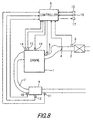
- an air flow meter 3 which detects an intake air amount
- a throttle 4 which adjusts the intake air amount
- an injector 5 which injects fuel into an intake pipe 2
- the injector 5 may inject fuel directly into a cylinder of the engine 1.
- a front catalyst 8 is formed in an exhaust pipe 7 of the engine 1, and a rear catalyst 9 is formed downstream of the front catalyst 8.
- the front catalyst 8 is a three-way catalyst, and reduces NOx in the exhaust gas and oxidizes HC and CO with maximum transformation efficiency when the engine 1 is running at the stoichiometric air-fuel ratio,
- a front O 2 sensor 10 and rear O 2 sensor 11 are provided respectively upstream and downstream of the front catalyst 8.
- the front O 2 sensor 10 and rear O 2 sensor 11 can detect whether the air-fuel ratios of the exhaust gas flowing into the front catalyst 8, and the exhaust flowing out of the front catalyst 8, are richer or leaner than the stoichiometric air-fuel ratio.
- a catalyst temperature sensor 12 which detects the temperature is also provided in the rear catalyst 9.
- a cooling water temperature signal from a cooling water temperature sensor 13 In addition to signals from the above-mentioned air flow meter 3, O 2 sensors 10 and 11, and the catalyst temperature sensor 12, a cooling water temperature signal from a cooling water temperature sensor 13, a Ref signal and Pos signal from a crank angle sensor 14, an accelerator depression amount signal from an accelerator position sensor 15, and a vehicle speed signal from a vehicle speed sensor 16, are input into a controller 6.
- the controller 6 controls the throttle 4, injector 5 and spark plug 19 based on these various signals.
- the controller 6 performs SOx discharge control under predetermined conditions and increases the temperature of the rear catalyst 9 to discharge the stored SOx.
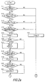
- a step S16 it is determined whether it is immediately after starting deterioration diagnosis based on the change of the flag Fdiag . If the flag Fdiag was zero on the immediately preceding occasion the routine was performed and the flag Fdiag is 1 on the present occasion, it is determined that diagnostic conditions have just been satisfied. When it is determined that diagnosis has just started, the routine proceeds to a step S17, otherwise the routine proceeds to a step S18.
- CTF is a counter which counts the number of inversions of the output of the front O 2 sensor 10
- HZR is a counter which counts the number of inversions of the output of the rear O 2 sensor 11
- HZRATE is the ratio of numbers of inversions of the outputs of the rear/front O 2 sensors which expresses the degree of deterioration of the front catalyst 8
- CT is a counter which counts the number of weighted average computations of HZRATE .
- a step S20 it is determined whether the output of the rear O 2 sensor 11 has crossed a threshold value which corresponds to the stoichiometric air-fuel ratio.
- the routine proceeds to a step S21 and HZR is counted, otherwise the routine proceeds to a step S22 of Fig. 2b.
- k is a weighting coefficient and is set to a value between zero and 1.
- step S28 the secondary diagnosis of the front catalyst 8 is performed.
- HZRATE is compared with the determined reference value HZRATEth , and when HZRATE ⁇ HZRATEth , it is determined that the front catalyst 8 has actually deteriorated, and the routine proceeds to a step S29.
- this secondary diagnosis if the diagnosis continues during a period which is CTth times the period during which the output of the front O 2 sensor 10 undergoes CTFth inversions, a diagnostic result of sufficient accuracy will be obtained.
- a flag Fdiag2 is set to 1 showing that the catalyst has been diagnosed as having deteriorated in the secondary diagnosis.
- a warning light 17 is turned on to alert the driver.
- the SOx trapping rate of the rear catalyst 9 is a value ranging from zero to 1, and has the following characteristics.
- a step S49 it is determined whether or not the estimated SOx storage amount SOX is smaller than a predetermined value SOXmin .
- the routine proceeds to a step S50, and the flag Fsox is set to zero showing that SOx discharge conditions are not satisfied.
- the predetermined value SOXmin is set to a small value near zero.
- This routine determines whether or not to perform SOx discharge control of the rear catalyst 9 based on the flag Fdiag1 , flag Fsox and catalyst temperature Tcat .
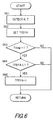
- Fig. 6 shows a routine for setting the target air-fuel ratio. This routine is performed at a predetermined interval, for example 10 milliseconds, by the controller 6. This routine sets the target air-fuel ratio (target equivalence ratio) according to the running conditions.
- a step S63 it is determined whether or not the front catalyst 8 is diagnosed as having deteriorated in the primary diagnosis based on the flag Fdiag1 .
- the routine proceeds to a step S64, otherwise the routine is terminated.
- the target equivalence ratio TFBYA set here is used for computing fuel injection amount in a routine described later, and also in various other routines as a representative value of air-fuel ratio.
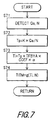
- Fig. 7 shows a routine for computing the fuel injection amount and fuel injection timing. This routine is performed by the controller 6 at a predetermined interval, for example 10 milliseconds.
- the fuel increase correction coefficient COEF collectively represents a fuel increase correction coefficient after startup and a water temperature increase correction coefficient.
- the fuel increase correction coefficient COEF is larger than 1 until warmup of the engine 1 is complete, but after warmup of the engine 1 is completed, it is 1.
- the fuel ratio feedback correction coefficient ⁇ is an air-fuel ratio feedback correction coefficient when the target equivalence ratio TFBYA is set to 1 and the air-fuel ratio is feedback controlled to the stoichiometric air-fuel ratio. It is computed according to the output of the front O 2 sensor 10.
- a fuel injection timing TITM is computed based on the fuel ignition amount Ti and engine rotation speed N .
- the computed fuel injection amount Ti and fuel injection timing TITM are stored in the memory of the controller 6, and read and used in a fuel injection routine performed in synchronism with the rotation of the engine 1. For example, a signal is output to the injector 5 so that a fuel amount obtained by adding an ineffectual injection amount Ts to the fuel injection amount Ti is injected at a crank angle determined by the fuel injection timing TITM .
- stratified charge combustion is performed when running at a lean air-fuel ratio, and uniform charge combustion is performed when running at the stoichiometric air-fuel ratio or a rich air-fuel ratio. For this reason, when running at a lean air-fuel ratio, the fuel injection timing TITM is set in the compression stroke. When running at the stoichiometric air-fuel ratio or a rich air-fuel ratio, the fuel injection timing TITM is set in the intake stroke.
- the controller 6 estimates the SOx amount stored in the rear catalyst 9. When the estimated SOx amount exceeds a predetermined amount, the amount of unburnt fuel and oxygen flowing into the rear catalyst 9 is increased, the catalyst temperature is increased by the heat of combustion, and the accumulated SOx is discharged.
- controller 6 performs deterioration diagnosis of the front catalyst 8 based on the output of the O 2 sensors 10, 11.
- a primary diagnosis is first performed based on the number of inversions of the output of the O 2 sensor 11 in an interval during which the output of the front O 2 sensor 10 performs a predetermined number or inversions, so as to diagnose deterioration of the front catalyst 8.
- this primary diagnosis is low, it can be performed even if the time for which deterioration diagnosis conditions are satisfied is short, and can therefore be performed even if there are not many diagnosis opportunities due to SOx discharge control or lean running.
- the secondary diagnosis gives a precise diagnosis result, it requires correspondingly more time than the primary diagnosis, but as lean air-fuel ratio running and SOx discharge control are prohibited when it is determined that the front catalyst 8 has deteriorated in the primary diagnosis, many opportunities are available for the secondary diagnosis.
- a simple primary diagnosis is first performed, and when it is determined in the primary diagnosis that the catalyst has deteriorated, lean air-fuel ratio running and SOx discharge control are prohibited, and the high precision secondary diagnosis is performed. Therefore, a precise deterioration diagnosis can be performed even when few diagnosis opportunities exist due to lean running or SOx discharge control. There is no need to reduce the lean running region or the SOx discharge control region to provide more diagnostic opportunities, and deterioration diagnosis can be performed together with lean air-fuel ratio running or SOx discharge control.
- a linear air-fuel ratio sensor may be used instead of the O 2 sensor for detecting the air-fuel ratio of the exhaust gas.
- an NOx sensor can be installed which detects NOx concentration downstream of the rear catalyst 9, and determination of SOx discharge conditions performed based on the output of this NOx sensor.
- NOx trapping performance declines and the NOx concentration downstream of the catalyst increases the greater the SOx storage amount, so it is determined that SOx discharge conditions are satisfied when the NOx concentration exceeds a predetermined value.
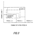
- the same result is obtained by setting an overlapping area between the region surrounded by the dot-and-dash line in Fig. 3 and the stoichiometric air-fuel ratio running region as the diagnosis region until it is diagnosed in the primary diagnosis that the front catalyst 8 has deteriorated, and then enlarging the diagnosis region to the whole area surrounded by the dot-and-dash line after it is diagnosed in the primary diagnosis that the front catalyst 8 deteriorated and performing stoichiometric air-fuel ratio running forcibly in the diagnosis region.
Landscapes
- Engineering & Computer Science (AREA)
- Chemical & Material Sciences (AREA)
- Combustion & Propulsion (AREA)
- Mechanical Engineering (AREA)
- General Engineering & Computer Science (AREA)
- Chemical Kinetics & Catalysis (AREA)
- Health & Medical Sciences (AREA)
- Toxicology (AREA)
- Exhaust Gas After Treatment (AREA)
- Electrical Control Of Air Or Fuel Supplied To Internal-Combustion Engine (AREA)
- Combined Controls Of Internal Combustion Engines (AREA)
Abstract
Description
a sensor which detects the air-fuel ratio of the exhaust gas downstream of the front three-way catalyst, a sensor which detects the running state of the engine, and a microprocessor. The microprocessor is programmed to determine whether or not conditions are satisfied for discharging SOx stored in the rear catalyst, perform SOx discharge control of the rear catalyst when conditions are satisfied for discharging SOx and the running state of the engine is within an SOx discharge running region, cause the air-fuel ratio of the engine to fluctuate periodically between rich and lean around the stoichiometric air-fuel ratio when the running state of the engine is in a catalyst diagnosis region whereof part overlaps with the SOx discharge running region, perform a primary diagnosis of whether or not the front three-way catalyst has deteriorated based on the air-fuel ratio of the exhaust gas downstream of the front three-way catalyst detected in a first period each time the first period elapses when the engine is running in the diagnosis region, and perform a secondary diagnosis of whether or not the front three-way catalyst has deteriorated based on the air-fuel ratio of the exhaust gas downstream of the front catalyst detected in a second period longer than the first period each time the second period elapses when the engine is running in the diagnosis region. The microprocessor is further programmed to prohibit the primary diagnosis and secondary diagnosis when SOx discharge control is performed, and prohibit SOx discharge control when it is diagnosed that the front three-way catalyst has deteriorated in the primary diagnosis.
- Activation of the front O2 sensor 10 is complete.
- Fuel increase amount control immediately after engine startup is completed (fuel increase correction coefficient COEF=1).
- The target air-fuel ratio is the stoichiometric air-fuel ratio (target equivalence ratio TFBYA=1).
- The SOx trapping rate increases as the SOx storage amount SOX of the
rear catalyst 9 decreases. When the SOx storage amount SOX is zero, the SOx trapping rate is a maximum. - The SOx trapping rate is a maximum when the temperature Tcat of the
rear catalyst 9 is a predetermined temperature, is smaller when the temperature is lower than the predetermined temperature, and is zero below the catalyst activation temperature. The SOx trapping rate decreases even at a temperature higher than the predetermined temperature, and is zero above the SOx discharge temperature Tcat2. - The SOx trapping rate decreases as the degree of leanness decreases, and is zero at a rich air-fuel ratio.
- The SOx discharge rate decreases as the SOx storage amount SOX of the
rear catalyst 9 decreases. When the SOx storage amount SOX is zero, the SOx discharge rate is zero. - The SOx discharge rate becomes lower, the lower the catalyst temperature Tcat of
the
rear catalyst 9, and is zero below the SOx discharge temperature Tcat2. - The SOx discharge rate decreases as the degree of richness decreases, and is zero at a lean air-fuel ratio.
Claims (11)
- An exhaust emission control device of an engine (1), comprising:an exhaust pipe (7),a front three-way catalyst (8) provided in the exhaust pipe (7),a rear catalyst (9) provided downstream of the front three-way catalyst (8) which traps or reduces NOx according to an air-fuel ratio of the inflowing exhaust gas,a sensor (11) which detects the air-fuel ratio of the exhaust gas downstream of the front three-way catalyst (8),a sensor (14, 15) which detect the running state of the engine (1), anda microprocessor (6) programmed to:determine whether or not conditions are satisfied for discharging SOx stored in the rear catalyst (9),perform SOx discharge control of the rear catalyst (9) when conditions are satisfied for discharging SOx and the running state of the engine (1) is within an SOx discharge running region,cause the air-fuel ratio of the engine (1) to fluctuate periodically between rich and lean around the stoichiometric air-fuel ratio when the running state of the engine (1) is in a catalyst diagnosis region whereof part overlaps with the SOx discharge running region,perform a primary diagnosis of whether or not the front three-way catalyst (8) has deteriorated based on the air-fuel ratio of the exhaust gas downstream of the front three-way catalyst (8) detected in a first period each time the first period elapses when the engine (1) is running in the diagnosis region,perform a secondary diagnosis of whether or not the front three-way catalyst (8) has deteriorated based on the air-fuel ratio of the exhaust gas downstream of the front three-way catalyst (8) detected in a second period longer than the first period each time the second period elapses when the engine (1) is running in the diagnosis region,prohibit the primary diagnosis and secondary diagnosis when SOx discharge control is performed, andprohibit SOx discharge control when it is diagnosed that the front three-way catalyst (8) has deteriorated in the primary diagnosis.
- An exhaust emission control device of an engine (1), comprising:an exhaust pipe (7),a three-way catalyst (8) provided in the exhaust pipe (7) which traps or reduces NOx according to an air-fuel ratio of the inflowing exhaust gas,a sensor (11) which detects the air-fuel ratio of the exhaust gas downstream of the three-way catalyst (8),a sensor (14, 15) which detect the running state of the engine (1), anda microprocessor (6) programmed to:determine whether or not conditions are satisfied for discharging SOx stored in the three-way catalyst (8),perform SOx discharge control of the three-way catalyst (8) when conditions are satisfied for discharging SOx and the running state of the engine (1) is within a SOx discharge running region,cause the air-fuel ratio of the engine (1) to fluctuate periodically between rich and lean around the stoichiometric air-fuel ratio when the running state of the engine (1) is in a catalyst diagnosis region whereof part overlaps with the SOx discharge running region,perform a primary diagnosis of whether or not the three-way catalyst (8) has deteriorated based on the air-fuel ratio of the exhaust gas downstream of the three-way catalyst (8) detected in a first period each time the first period elapses when the engine (1) is running in the diagnosis region,perform a secondary diagnosis of whether or not the three-way catalyst (8) has deteriorated based on the air-fuel ratio of the exhaust gas downstream of the three-way catalyst (8) detected in a second period longer than the first period each time the second period elapses when the engine (1) is running in the diagnosis region,prohibit the primary diagnosis and secondary diagnosis when SOx discharge control is performed, andprohibit SOx discharge control when it is diagnosed that the three-way catalyst (8) has deteriorated in the primary diagnosis.
- An exhaust emission control device as defined in Claim 1 or 2, wherein the microprocessor (6) is further programmed to:cancel the prohibition of SOx discharge control when it is determined in the secondary diagnosis that the three-way catalyst (8) has not deteriorated.
- An exhaust emission control device of an engine (1), comprising:an exhaust pipe (7),a three-way catalyst (8) provided in the exhaust pipe (7),a sensor (11) which detects the air-fuel ratio of the exhaust gas downstream of the three-way catalyst (8),a sensor (14, 15) which detect the running state of the engine (1), anda microprocessor (6) programmed to:control the air-fuel ratio of the engine (1) to a lean value when the running state of the engine (1) is in a lean air-fuel ratio running region,cause the air-fuel ratio of the engine (1) to fluctuate periodically between rich and lean around the stoichiometric air-fuel ratio when the running state of the engine (1) is in a catalyst diagnosis region and lean air-fuel ratio control is not being performed,perform a primary diagnosis of whether or not the three-way catalyst (8) has deteriorated based on the air-fuel ratio of the exhaust gas downstream of the three-way catalyst (8) detected in a first period each time the first period elapses when the engine (1) is running in the diagnosis region,perform a secondary diagnosis of whether or not the three-way catalyst (8) has deteriorated based on the air-fuel ratio of the exhaust gas downstream of the three-way catalyst (8) detected in a second period longer than the first period each time the second period elapses when the engine (1) is running in the diagnosis region,prohibit the primary diagnosis and secondary diagnosis when lean air-fuel ratio control is performed, andprohibit lean air-fuel ratio control when it is diagnosed that the three-way catalyst (8) has deteriorated in the primary diagnosis.
- An exhaust emission control device as defined in Claim 4, wherein the microprocessor (6) is further programmed to:cancel the prohibition of lean air-fuel ratio control when it is determined in the secondary diagnosis that the three-way catalyst (8) has not deteriorated.
- An exhaust emission control device of an engine (1), comprising:an exhaust pipe (7),a three-way catalyst (8) provided in the exhaust pipe (7),a sensor (11) which detects the air-fuel ratio of the exhaust gas downstream of the three-way catalyst (8),a sensor (14, 15) which detect the running state of the engine (1), anda microprocessor (6) programmed to:control the air-fuel ratio of the engine (1) to a lean air-fuel ratio when the running state of the engine (1) is in a lean air-fuel ratio running region,cause the air-fuel ratio of the engine (1) to fluctuate periodically between rich and lean around the stoichiometric air-fuel ratio with preference to lean air-fuel ratio control when the running state of the engine (1) is in a catalyst diagnosis region,perform a primary diagnosis of whether or not the three-way catalyst (8) has deteriorated based on the air-fuel ratio of the exhaust gas downstream of the three-way catalyst (8) detected in a first period each time the first period elapses when the engine (1) is running in the diagnosis region,perform a secondary diagnosis of whether or not the three-way catalyst (8) has deteriorated based on the air-fuel ratio of the exhaust gas downstream of the three-way catalyst (8) detected in a second period longer than the first period each time the second period elapses when the engine (1) is running in the diagnosis region, andset the diagnosis region outside the lean air-fuel ratio running region until it is determined in the primary diagnosis that the front catalyst (8) has deteriorated, and after it is diagnosed as having deteriorated, enlarge the diagnosis region to a region overlapping with the lean air-fuel ratio running region.
- An exhaust gas emission control device as defined in Claim 6, wherein the microprocessor (6) is further programmed to:cancel the enlargement of the diagnosis region when it is determined in the secondary diagnosis that the three-way catalyst (8) has not deteriorated.
- An exhaust emission control device of an engine (1), comprising:an exhaust pipe (7),a front three-way catalyst (8) provided in the exhaust pipe (7),a rear catalyst (9) provided downstream of the front three-way catalyst (8) which traps or reduces NOx according to an air-fuel ratio of the inflowing exhaust gas,a sensor (11) which detects the air-fuel ratio of the exhaust gas downstream of the front three-way catalyst (8),a sensor (14, 15) which detect the running state of the engine (1), andmeans for determining whether or not conditions are satisfied for discharging SOx stored in the rear catalyst (9),means for performing SOx discharge control of the rear catalyst (9) when conditions are satisfied for discharging SOx and the running state of the engine (1) is within an SOx discharge running region,means for causing the air-fuel ratio of the engine (1) to fluctuate periodically between rich and lean around the stoichiometric air-fuel ratio when the running state of the engine (1) is in a catalyst diagnosis region whereof part overlaps with the SOx discharge running region,means for performing a primary diagnosis of whether or not the front three-way catalyst (8) has deteriorated based on the air-fuel ratio of the exhaust gas downstream of the front three-way catalyst (8) detected in a first period each time the first period elapses when the engine (1) is running in the diagnosis region,means for performing a secondary diagnosis of whether or not the front three-way catalyst (8) has deteriorated based on the air-fuel ratio of the exhaust gas downstream of the front three-way catalyst (8) detected in a second period longer than the first period each time the second period elapses when the engine (1) is running in the diagnosis region,means for prohibiting the primary diagnosis and secondary diagnosis when SOx discharge control is performed, andmeans for prohibiting SOx discharge control when it is diagnosed that the front three-way catalyst (8) has deteriorated in the primary diagnosis.
- An exhaust emission control device of an engine (1), comprising:an exhaust pipe (7),a three-way catalyst (8) provided in the exhaust pipe (7) which traps or reduces NOx according to an air-fuel ratio of the inflowing exhaust gas,means for detecting the air-fuel ratio of the exhaust gas downstream of the three-way catalyst (8),means for detecting the running state of the engine (1),means for determining whether or not conditions are satisfied for discharging SOx stored in the three-way catalyst (8),means for performing SOx discharge control of the three-way catalyst (8) when conditions are satisfied for discharging SOx and the running state of the engine (1) is within a SOx discharge running region,means for causing the air-fuel ratio of the engine (1) to fluctuate periodically between rich and lean around the stoichiometric air-fuel ratio when the running state of the engine (1) is in a catalyst diagnosis region whereof part overlaps with the SOx discharge running region,means for performing a primary diagnosis of whether or not the three-way catalyst (8) has deteriorated based on the air-fuel ratio of the exhaust gas downstream of the three-way catalyst (8) detected in a first period each time the first period elapses when the engine (1) is running in the diagnosis region,means for performing a secondary diagnosis of whether or not the three-way catalyst (8) has deteriorated based on the air-fuel ratio of the exhaust gas downstream of the three-way catalyst (8) detected in a second period longer than the first period each time the second period elapses when the engine (1) is running in the diagnosis region,means for prohibiting the primary diagnosis and secondary diagnosis when SOx discharge control is performed, andmeans for prohibiting SOx discharge control when it is diagnosed that the three-way catalyst (8) has deteriorated in the primary diagnosis.
- An exhaust emission control device of an engine (1), comprising:an exhaust pipe (7),a three-way catalyst (8) provided in the exhaust pipe (7),means for detecting the air-fuel ratio of the exhaust gas downstream of the three-way catalyst (8),means for detecting the running state of the engine (1),means for controlling the air-fuel ratio of the engine (1) to a lean value when the running state of the engine (1) is in a lean air-fuel ratio running region,means for causing the air-fuel ratio of the engine (1) to fluctuate periodically between rich and lean around the stoichiometric air-fuel ratio when the running state of the engine (1) is in a catalyst diagnosis region and lean air-fuel ratio control is not being performed,means for performing a primary diagnosis of whether or not the three-way catalyst (8) has deteriorated based on the air-fuel ratio of the exhaust gas downstream of the three-way catalyst (8) detected in a first period each time the first period elapses when the engine (1) is running in the diagnosis region,means for performing a secondary diagnosis of whether or not the three-way catalyst (8) has deteriorated based on the air-fuel ratio of the exhaust gas downstream of the three-way catalyst (8) detected in a second period longer than the first period each time the second period elapses when the engine (1) is running in the diagnosis region,means for prohibiting the primary diagnosis and secondary diagnosis when lean air-fuel ratio control is performed, andmeans for prohibiting lean air-fuel ratio control when it is diagnosed that the three-way catalyst (8) has deteriorated in the primary diagnosis.
- An exhaust emission control device of an engine (1), comprising:an exhaust pipe (7),a three-way catalyst (8) provided in the exhaust pipe (7),means for detecting the air-fuel ratio of the exhaust gas downstream of the three-way catalyst (8),means for detecting the running state of the engine (1),means for controlling the air-fuel ratio of the engine (1) to a lean air-fuel ratio when the running state of the engine (1) is in a lean air-fuel ratio running region,means for causing the air-fuel ratio of the engine (1) to fluctuate periodically between rich and lean around the stoichiometric air-fuel ratio with preference to lean air-fuel ratio control when the running state of the engine (1) is in a catalyst diagnosis region,means for performing a primary diagnosis of whether or not the three-way catalyst (8) has deteriorated based on the air-fuel ratio of the exhaust gas downstream of the three-way catalyst (8) detected in a first period each time the first period elapses when the engine (1) is running in the diagnosis region,means for performing a secondary diagnosis of whether or not the three-way catalyst (8) has deteriorated based on the air-fuel ratio of the exhaust gas downstream of the three-way catalyst (8) detected in a second period longer than the first period each time the second period elapses when the engine (1) is running in the diagnosis region, andmeans for setting the diagnosis region outside the lean air-fuel ratio running region until it is determined in the primary diagnosis that the front catalyst (8) has deteriorated, and after it is diagnosed as having deteriorated, enlarging the diagnosis region to a region overlapping with the lean air-fuel ratio running region.
Applications Claiming Priority (2)
| Application Number | Priority Date | Filing Date | Title |
|---|---|---|---|
| JP8162199 | 1999-03-25 | ||
| JP08162199A JP3649034B2 (en) | 1999-03-25 | 1999-03-25 | Engine exhaust purification system |
Publications (3)
| Publication Number | Publication Date |
|---|---|
| EP1039109A2 true EP1039109A2 (en) | 2000-09-27 |
| EP1039109A3 EP1039109A3 (en) | 2001-10-24 |
| EP1039109B1 EP1039109B1 (en) | 2003-06-04 |
Family
ID=13751412
Family Applications (1)
| Application Number | Title | Priority Date | Filing Date |
|---|---|---|---|
| EP00106270A Expired - Lifetime EP1039109B1 (en) | 1999-03-25 | 2000-03-22 | Exhaust emission control device of internal combustion engine |
Country Status (4)
| Country | Link |
|---|---|
| US (1) | US6233923B1 (en) |
| EP (1) | EP1039109B1 (en) |
| JP (1) | JP3649034B2 (en) |
| DE (1) | DE60003105T2 (en) |
Cited By (2)
| Publication number | Priority date | Publication date | Assignee | Title |
|---|---|---|---|---|
| FR2841936A1 (en) * | 2002-07-04 | 2004-01-09 | Volkswagen Ag | METHOD FOR THERMAL REGENERATION OF AN EXHAUST PURIFICATION DEVICE, AND DEVICE FOR AN INTERNAL COMBUSTION ENGINE |
| EP1544430A1 (en) * | 2003-12-20 | 2005-06-22 | DaimlerChrysler AG | Method for operating a NOx storage catalyst |
Families Citing this family (42)
| Publication number | Priority date | Publication date | Assignee | Title |
|---|---|---|---|---|
| EP0915244B1 (en) * | 1997-11-10 | 2003-08-06 | Mitsubishi Jidosha Kogyo Kabushiki Kaisha | Exhaust gas purifying apparatus of internal combustion engine |
| US6360530B1 (en) | 2000-03-17 | 2002-03-26 | Ford Global Technologies, Inc. | Method and apparatus for measuring lean-burn engine emissions |
| JP3835140B2 (en) * | 2000-08-30 | 2006-10-18 | 日産自動車株式会社 | Engine air-fuel ratio control device |
| US6691507B1 (en) * | 2000-10-16 | 2004-02-17 | Ford Global Technologies, Llc | Closed-loop temperature control for an emission control device |
| JP3659193B2 (en) * | 2001-06-08 | 2005-06-15 | 日産自動車株式会社 | Exhaust gas purification system for internal combustion engine |
| US6694244B2 (en) | 2001-06-19 | 2004-02-17 | Ford Global Technologies, Llc | Method for quantifying oxygen stored in a vehicle emission control device |
| US6463733B1 (en) | 2001-06-19 | 2002-10-15 | Ford Global Technologies, Inc. | Method and system for optimizing open-loop fill and purge times for an emission control device |
| US6487853B1 (en) | 2001-06-19 | 2002-12-03 | Ford Global Technologies. Inc. | Method and system for reducing lean-burn vehicle emissions using a downstream reductant sensor |
| US6553754B2 (en) | 2001-06-19 | 2003-04-29 | Ford Global Technologies, Inc. | Method and system for controlling an emission control device based on depletion of device storage capacity |
| US6591604B2 (en) * | 2001-06-19 | 2003-07-15 | Ford Global Technologies, Llc | Oxygen storage capacity estimation |
| US6650991B2 (en) | 2001-06-19 | 2003-11-18 | Ford Global Technologies, Llc | Closed-loop method and system for purging a vehicle emission control |
| US6467259B1 (en) | 2001-06-19 | 2002-10-22 | Ford Global Technologies, Inc. | Method and system for operating dual-exhaust engine |
| US6453666B1 (en) | 2001-06-19 | 2002-09-24 | Ford Global Technologies, Inc. | Method and system for reducing vehicle tailpipe emissions when operating lean |
| US6539706B2 (en) | 2001-06-19 | 2003-04-01 | Ford Global Technologies, Inc. | Method and system for preconditioning an emission control device for operation about stoichiometry |
| US6604504B2 (en) | 2001-06-19 | 2003-08-12 | Ford Global Technologies, Llc | Method and system for transitioning between lean and stoichiometric operation of a lean-burn engine |
| US6502387B1 (en) | 2001-06-19 | 2003-01-07 | Ford Global Technologies, Inc. | Method and system for controlling storage and release of exhaust gas constituents in an emission control device |
| US6615577B2 (en) | 2001-06-19 | 2003-09-09 | Ford Global Technologies, Llc | Method and system for controlling a regeneration cycle of an emission control device |
| US6490860B1 (en) | 2001-06-19 | 2002-12-10 | Ford Global Technologies, Inc. | Open-loop method and system for controlling the storage and release cycles of an emission control device |
| US6691020B2 (en) | 2001-06-19 | 2004-02-10 | Ford Global Technologies, Llc | Method and system for optimizing purge of exhaust gas constituent stored in an emission control device |
| US6546718B2 (en) | 2001-06-19 | 2003-04-15 | Ford Global Technologies, Inc. | Method and system for reducing vehicle emissions using a sensor downstream of an emission control device |
| JP4135428B2 (en) * | 2002-08-01 | 2008-08-20 | 日産自動車株式会社 | Apparatus and method for exhaust gas purification of internal combustion engine |
| US7134273B2 (en) | 2002-09-04 | 2006-11-14 | Ford Global Technologies, Llc | Exhaust emission control and diagnostics |
| US6701707B1 (en) | 2002-09-04 | 2004-03-09 | Ford Global Technologies, Llc | Exhaust emission diagnostics |
| US6865883B2 (en) * | 2002-12-12 | 2005-03-15 | Detroit Diesel Corporation | System and method for regenerating exhaust system filtering and catalyst components |
| US20080163610A1 (en) * | 2007-01-05 | 2008-07-10 | Matthew Thomas Baird | Method and system for regenerating exhaust system filtering and catalyst components using variable high engine idle |
| JP4816606B2 (en) | 2007-09-18 | 2011-11-16 | トヨタ自動車株式会社 | Exhaust gas purification system for internal combustion engine |
| JP4615558B2 (en) * | 2007-11-13 | 2011-01-19 | 本田技研工業株式会社 | Exhaust gas purification device for internal combustion engine |
| US20110185708A1 (en) * | 2010-01-29 | 2011-08-04 | Eaton Corporation | Adaptive Desulfation Control Algorithm |
| JP6597593B2 (en) * | 2016-12-27 | 2019-10-30 | トヨタ自動車株式会社 | Control device for internal combustion engine |
| US11156177B2 (en) * | 2019-10-04 | 2021-10-26 | Ford Global Technologies, Llc | Methods and systems for catalyst monitoring enablement |
| US11813926B2 (en) | 2020-08-20 | 2023-11-14 | Denso International America, Inc. | Binding agent and olfaction sensor |
| US11760170B2 (en) | 2020-08-20 | 2023-09-19 | Denso International America, Inc. | Olfaction sensor preservation systems and methods |
| US11881093B2 (en) | 2020-08-20 | 2024-01-23 | Denso International America, Inc. | Systems and methods for identifying smoking in vehicles |
| US11760169B2 (en) | 2020-08-20 | 2023-09-19 | Denso International America, Inc. | Particulate control systems and methods for olfaction sensors |
| US12377711B2 (en) | 2020-08-20 | 2025-08-05 | Denso International America, Inc. | Vehicle feature control systems and methods based on smoking |
| US11636870B2 (en) | 2020-08-20 | 2023-04-25 | Denso International America, Inc. | Smoking cessation systems and methods |
| US12017506B2 (en) | 2020-08-20 | 2024-06-25 | Denso International America, Inc. | Passenger cabin air control systems and methods |
| US12251991B2 (en) | 2020-08-20 | 2025-03-18 | Denso International America, Inc. | Humidity control for olfaction sensors |
| US11828210B2 (en) | 2020-08-20 | 2023-11-28 | Denso International America, Inc. | Diagnostic systems and methods of vehicles using olfaction |
| US12269315B2 (en) | 2020-08-20 | 2025-04-08 | Denso International America, Inc. | Systems and methods for measuring and managing odor brought into rental vehicles |
| US11932080B2 (en) | 2020-08-20 | 2024-03-19 | Denso International America, Inc. | Diagnostic and recirculation control systems and methods |
| CN115075927B (en) * | 2022-06-22 | 2023-05-23 | 东风汽车集团股份有限公司 | Mixed motor vehicle type engine catalyst degradation diagnosis method |
Family Cites Families (15)
| Publication number | Priority date | Publication date | Assignee | Title |
|---|---|---|---|---|
| JP2605586B2 (en) * | 1992-07-24 | 1997-04-30 | トヨタ自動車株式会社 | Exhaust gas purification device for internal combustion engine |
| US5433074A (en) * | 1992-07-30 | 1995-07-18 | Toyota Jidosha Kabushiki Kaisha | Exhaust gas purification device for an engine |
| JP3228006B2 (en) * | 1994-06-30 | 2001-11-12 | トヨタ自動車株式会社 | Exhaust purification element deterioration detection device for internal combustion engine |
| JP2836522B2 (en) * | 1995-03-24 | 1998-12-14 | トヨタ自動車株式会社 | Exhaust gas purification device for internal combustion engine |
| JP3449124B2 (en) | 1996-08-12 | 2003-09-22 | トヨタ自動車株式会社 | Exhaust gas purification device for internal combustion engine |
| JP3645704B2 (en) * | 1997-03-04 | 2005-05-11 | トヨタ自動車株式会社 | Exhaust gas purification device for internal combustion engine |
| US6105365A (en) * | 1997-04-08 | 2000-08-22 | Engelhard Corporation | Apparatus, method, and system for concentrating adsorbable pollutants and abatement thereof |
| JP3424557B2 (en) * | 1997-08-06 | 2003-07-07 | マツダ株式会社 | Engine exhaust purification device |
| JP3361252B2 (en) * | 1997-08-14 | 2003-01-07 | 本田技研工業株式会社 | Exhaust gas purification device for internal combustion engine |
| JP3264226B2 (en) * | 1997-08-25 | 2002-03-11 | トヨタ自動車株式会社 | Exhaust gas purification device for internal combustion engine |
| US5974788A (en) * | 1997-08-29 | 1999-11-02 | Ford Global Technologies, Inc. | Method and apparatus for desulfating a nox trap |
| JP3430879B2 (en) * | 1997-09-19 | 2003-07-28 | トヨタ自動車株式会社 | Exhaust gas purification device for internal combustion engine |
| US6138453A (en) * | 1997-09-19 | 2000-10-31 | Toyota Jidosha Kabushiki Kaisha | Exhaust gas purification device for an internal combustion engine |
| DE19747222C1 (en) * | 1997-10-25 | 1999-03-04 | Daimler Benz Ag | Lean burn internal combustion engine with periodic nitrogen oxide(s) storage catalyst regeneration control |
| US6128899A (en) * | 1998-04-17 | 2000-10-10 | Honda Giken Kogyo Kabushiki Kaisha | Exhaust gas purification system for internal combustion engine |
-
1999
- 1999-03-25 JP JP08162199A patent/JP3649034B2/en not_active Expired - Lifetime
-
2000
- 2000-03-21 US US09/532,325 patent/US6233923B1/en not_active Expired - Lifetime
- 2000-03-22 DE DE60003105T patent/DE60003105T2/en not_active Expired - Lifetime
- 2000-03-22 EP EP00106270A patent/EP1039109B1/en not_active Expired - Lifetime
Cited By (2)
| Publication number | Priority date | Publication date | Assignee | Title |
|---|---|---|---|---|
| FR2841936A1 (en) * | 2002-07-04 | 2004-01-09 | Volkswagen Ag | METHOD FOR THERMAL REGENERATION OF AN EXHAUST PURIFICATION DEVICE, AND DEVICE FOR AN INTERNAL COMBUSTION ENGINE |
| EP1544430A1 (en) * | 2003-12-20 | 2005-06-22 | DaimlerChrysler AG | Method for operating a NOx storage catalyst |
Also Published As
| Publication number | Publication date |
|---|---|
| DE60003105D1 (en) | 2003-07-10 |
| US6233923B1 (en) | 2001-05-22 |
| DE60003105T2 (en) | 2003-12-11 |
| EP1039109A3 (en) | 2001-10-24 |
| EP1039109B1 (en) | 2003-06-04 |
| JP2000274228A (en) | 2000-10-03 |
| JP3649034B2 (en) | 2005-05-18 |
Similar Documents
| Publication | Publication Date | Title |
|---|---|---|
| EP1039109B1 (en) | Exhaust emission control device of internal combustion engine | |
| US6679050B1 (en) | Exhaust emission control device for internal combustion engine | |
| US6263666B1 (en) | Exhaust emission control device for internal combustion engine | |
| US6216450B1 (en) | Exhaust emission control system for internal combustion engine | |
| US5533332A (en) | Method and apparatus for self diagnosis of an internal combustion engine | |
| US6931838B2 (en) | Engine exhaust gas leak diagnosis | |
| JPH0734860A (en) | Catalyst deterioration detector | |
| JPH09236569A (en) | Function diagnosis device for exhaust gas purification device of internal combustion engine | |
| EP1184555A2 (en) | Engine exhaust purification device | |
| US7293404B2 (en) | Control device for internal combustion engine | |
| JP4193869B2 (en) | Exhaust gas purification catalyst deterioration diagnosis device | |
| JP3149714B2 (en) | Catalyst deterioration diagnosis device for internal combustion engine | |
| JP3528698B2 (en) | Fuel sulfur concentration estimation device | |
| WO2009110170A1 (en) | Exhaust system diagnostic apparatus of internal combustion engine | |
| US5557929A (en) | Control system for internal combustion engine equipped with exhaust gas purifying catalyst | |
| US12092002B2 (en) | Control device for internal combustion engine and catalyst deterioration diagnostic method | |
| JP2003176714A (en) | Function diagnosis device for exhaust gas purification device of internal combustion engine | |
| JP2737482B2 (en) | Degradation diagnosis device for catalytic converter device in internal combustion engine | |
| JPH0933478A (en) | Oxygen sensor response diagnostic device for internal combustion engine | |
| JP2001098981A (en) | Catalyst deterioration determination device for internal combustion engine | |
| JP3318702B2 (en) | Catalyst deterioration diagnosis device for internal combustion engine | |
| JP3089969B2 (en) | Degradation diagnosis device for exhaust purification catalyst | |
| JP2003254135A (en) | Air-fuel ratio sensor abnormality diagnosis device | |
| JP3601210B2 (en) | Engine air-fuel ratio control device | |
| JP2671877B2 (en) | Catalyst deterioration determination device |
Legal Events
| Date | Code | Title | Description |
|---|---|---|---|
| PUAI | Public reference made under article 153(3) epc to a published international application that has entered the european phase |
Free format text: ORIGINAL CODE: 0009012 |
|
| 17P | Request for examination filed |
Effective date: 20000322 |
|
| AK | Designated contracting states |
Kind code of ref document: A2 Designated state(s): AT BE CH CY DE DK ES FI FR GB GR IE IT LI LU MC NL PT SE Kind code of ref document: A2 Designated state(s): DE FR GB |
|
| AX | Request for extension of the european patent |
Free format text: AL;LT;LV;MK;RO;SI |
|
| PUAL | Search report despatched |
Free format text: ORIGINAL CODE: 0009013 |
|
| AK | Designated contracting states |
Kind code of ref document: A3 Designated state(s): AT BE CH CY DE DK ES FI FR GB GR IE IT LI LU MC NL PT SE |
|
| AX | Request for extension of the european patent |
Free format text: AL;LT;LV;MK;RO;SI |
|
| RIC1 | Information provided on ipc code assigned before grant |
Free format text: 7F 01N 11/00 A, 7F 01N 3/08 B, 7F 01N 9/00 B, 7F 02D 41/02 B |
|
| 17Q | First examination report despatched |
Effective date: 20020123 |
|
| AKX | Designation fees paid |
Free format text: DE FR GB |
|
| GRAH | Despatch of communication of intention to grant a patent |
Free format text: ORIGINAL CODE: EPIDOS IGRA |
|
| GRAH | Despatch of communication of intention to grant a patent |
Free format text: ORIGINAL CODE: EPIDOS IGRA |
|
| GRAA | (expected) grant |
Free format text: ORIGINAL CODE: 0009210 |
|
| AK | Designated contracting states |
Designated state(s): DE FR GB |
|
| REG | Reference to a national code |
Ref country code: GB Ref legal event code: FG4D |
|
| REF | Corresponds to: |
Ref document number: 60003105 Country of ref document: DE Date of ref document: 20030710 Kind code of ref document: P |
|
| ET | Fr: translation filed | ||
| PLBE | No opposition filed within time limit |
Free format text: ORIGINAL CODE: 0009261 |
|
| STAA | Information on the status of an ep patent application or granted ep patent |
Free format text: STATUS: NO OPPOSITION FILED WITHIN TIME LIMIT |
|
| 26N | No opposition filed |
Effective date: 20040305 |
|
| REG | Reference to a national code |
Ref country code: FR Ref legal event code: PLFP Year of fee payment: 17 |
|
| REG | Reference to a national code |
Ref country code: FR Ref legal event code: PLFP Year of fee payment: 18 |
|
| REG | Reference to a national code |
Ref country code: FR Ref legal event code: PLFP Year of fee payment: 19 |
|
| PGFP | Annual fee paid to national office [announced via postgrant information from national office to epo] |
Ref country code: GB Payment date: 20190320 Year of fee payment: 20 Ref country code: DE Payment date: 20190312 Year of fee payment: 20 |
|
| PGFP | Annual fee paid to national office [announced via postgrant information from national office to epo] |
Ref country code: FR Payment date: 20190213 Year of fee payment: 20 |
|
| REG | Reference to a national code |
Ref country code: DE Ref legal event code: R071 Ref document number: 60003105 Country of ref document: DE |
|
| REG | Reference to a national code |
Ref country code: GB Ref legal event code: PE20 Expiry date: 20200321 |
|
| PG25 | Lapsed in a contracting state [announced via postgrant information from national office to epo] |
Ref country code: GB Free format text: LAPSE BECAUSE OF EXPIRATION OF PROTECTION Effective date: 20200321 |