EP1038849A1 - Low emissivity glass and glass articles made of low emissivity glass - Google Patents
Low emissivity glass and glass articles made of low emissivity glass Download PDFInfo
- Publication number
- EP1038849A1 EP1038849A1 EP00400751A EP00400751A EP1038849A1 EP 1038849 A1 EP1038849 A1 EP 1038849A1 EP 00400751 A EP00400751 A EP 00400751A EP 00400751 A EP00400751 A EP 00400751A EP 1038849 A1 EP1038849 A1 EP 1038849A1
- Authority
- EP
- European Patent Office
- Prior art keywords
- film
- glass
- oxide based
- based film
- sno
- Prior art date
- Legal status (The legal status is an assumption and is not a legal conclusion. Google has not performed a legal analysis and makes no representation as to the accuracy of the status listed.)
- Granted
Links
- 239000011521 glass Substances 0.000 title claims abstract description 213
- 239000005344 low-emissivity glass Substances 0.000 title claims abstract description 35
- XOLBLPGZBRYERU-UHFFFAOYSA-N tin dioxide Chemical compound O=[Sn]=O XOLBLPGZBRYERU-UHFFFAOYSA-N 0.000 claims abstract description 311
- VYPSYNLAJGMNEJ-UHFFFAOYSA-N Silicium dioxide Chemical compound O=[Si]=O VYPSYNLAJGMNEJ-UHFFFAOYSA-N 0.000 claims abstract description 184
- 239000000758 substrate Substances 0.000 claims abstract description 83
- ATJFFYVFTNAWJD-UHFFFAOYSA-N Tin Chemical compound [Sn] ATJFFYVFTNAWJD-UHFFFAOYSA-N 0.000 claims abstract description 47
- 229910052787 antimony Inorganic materials 0.000 claims abstract description 47
- WATWJIUSRGPENY-UHFFFAOYSA-N antimony atom Chemical compound [Sb] WATWJIUSRGPENY-UHFFFAOYSA-N 0.000 claims abstract description 47
- 229910044991 metal oxide Inorganic materials 0.000 claims abstract description 40
- 229910001887 tin oxide Inorganic materials 0.000 claims abstract description 37
- 229910052731 fluorine Inorganic materials 0.000 claims abstract description 22
- 239000011737 fluorine Substances 0.000 claims abstract description 22
- 229910052814 silicon oxide Inorganic materials 0.000 claims abstract description 10
- PXGOKWXKJXAPGV-UHFFFAOYSA-N Fluorine Chemical compound FF PXGOKWXKJXAPGV-UHFFFAOYSA-N 0.000 claims abstract 2
- 239000002994 raw material Substances 0.000 claims description 100
- ZAMOUSCENKQFHK-UHFFFAOYSA-N Chlorine atom Chemical compound [Cl] ZAMOUSCENKQFHK-UHFFFAOYSA-N 0.000 claims description 15
- 239000000460 chlorine Substances 0.000 claims description 15
- 229910052801 chlorine Inorganic materials 0.000 claims description 15
- 238000000151 deposition Methods 0.000 claims description 3
- 239000007790 solid phase Substances 0.000 claims description 3
- 238000002834 transmittance Methods 0.000 abstract description 44
- 230000007423 decrease Effects 0.000 abstract description 5
- IJGRMHOSHXDMSA-UHFFFAOYSA-N Atomic nitrogen Chemical compound N#N IJGRMHOSHXDMSA-UHFFFAOYSA-N 0.000 description 98
- 239000000377 silicon dioxide Substances 0.000 description 86
- 229910052681 coesite Inorganic materials 0.000 description 84
- 229910052906 cristobalite Inorganic materials 0.000 description 84
- 229910052682 stishovite Inorganic materials 0.000 description 84
- 229910052905 tridymite Inorganic materials 0.000 description 84
- YMLFYGFCXGNERH-UHFFFAOYSA-K butyltin trichloride Chemical compound CCCC[Sn](Cl)(Cl)Cl YMLFYGFCXGNERH-UHFFFAOYSA-K 0.000 description 57
- QVGXLLKOCUKJST-UHFFFAOYSA-N atomic oxygen Chemical compound [O] QVGXLLKOCUKJST-UHFFFAOYSA-N 0.000 description 50
- 239000001301 oxygen Substances 0.000 description 50
- 229910052760 oxygen Inorganic materials 0.000 description 50
- 239000007789 gas Substances 0.000 description 49
- 229910052757 nitrogen Inorganic materials 0.000 description 49
- 230000005855 radiation Effects 0.000 description 31
- 230000000052 comparative effect Effects 0.000 description 30
- DAMJCWMGELCIMI-UHFFFAOYSA-N benzyl n-(2-oxopyrrolidin-3-yl)carbamate Chemical compound C=1C=CC=CC=1COC(=O)NC1CCNC1=O DAMJCWMGELCIMI-UHFFFAOYSA-N 0.000 description 28
- BLRPTPMANUNPDV-UHFFFAOYSA-N Silane Chemical compound [SiH4] BLRPTPMANUNPDV-UHFFFAOYSA-N 0.000 description 21
- 238000005229 chemical vapour deposition Methods 0.000 description 21
- YCKRFDGAMUMZLT-UHFFFAOYSA-N Fluorine atom Chemical compound [F] YCKRFDGAMUMZLT-UHFFFAOYSA-N 0.000 description 20
- KRHYYFGTRYWZRS-UHFFFAOYSA-N Fluorane Chemical compound F KRHYYFGTRYWZRS-UHFFFAOYSA-N 0.000 description 19
- 239000005357 flat glass Substances 0.000 description 19
- 229910000040 hydrogen fluoride Inorganic materials 0.000 description 19
- 230000015572 biosynthetic process Effects 0.000 description 15
- 238000005507 spraying Methods 0.000 description 15
- VGGSQFUCUMXWEO-UHFFFAOYSA-N Ethene Chemical compound C=C VGGSQFUCUMXWEO-UHFFFAOYSA-N 0.000 description 14
- 239000005977 Ethylene Substances 0.000 description 14
- 238000004519 manufacturing process Methods 0.000 description 12
- XLYOFNOQVPJJNP-UHFFFAOYSA-N water Chemical compound O XLYOFNOQVPJJNP-UHFFFAOYSA-N 0.000 description 11
- 239000000843 powder Substances 0.000 description 10
- 235000012239 silicon dioxide Nutrition 0.000 description 10
- XUIMIQQOPSSXEZ-UHFFFAOYSA-N Silicon Chemical compound [Si] XUIMIQQOPSSXEZ-UHFFFAOYSA-N 0.000 description 9
- 239000000654 additive Substances 0.000 description 9
- 230000000996 additive effect Effects 0.000 description 9
- 229910052710 silicon Inorganic materials 0.000 description 9
- 239000010703 silicon Substances 0.000 description 9
- 229910001868 water Inorganic materials 0.000 description 9
- 230000008018 melting Effects 0.000 description 8
- 238000002844 melting Methods 0.000 description 8
- 239000006060 molten glass Substances 0.000 description 8
- 239000000126 substance Substances 0.000 description 8
- 150000001463 antimony compounds Chemical class 0.000 description 7
- 150000002222 fluorine compounds Chemical class 0.000 description 7
- 239000000203 mixture Substances 0.000 description 7
- 238000006243 chemical reaction Methods 0.000 description 6
- 238000009434 installation Methods 0.000 description 6
- -1 antimony Chemical compound 0.000 description 5
- 238000010438 heat treatment Methods 0.000 description 5
- 238000003475 lamination Methods 0.000 description 5
- 239000000463 material Substances 0.000 description 5
- 238000005979 thermal decomposition reaction Methods 0.000 description 5
- 150000003606 tin compounds Chemical class 0.000 description 5
- CDBYLPFSWZWCQE-UHFFFAOYSA-L Sodium Carbonate Chemical compound [Na+].[Na+].[O-]C([O-])=O CDBYLPFSWZWCQE-UHFFFAOYSA-L 0.000 description 4
- 150000001875 compounds Chemical class 0.000 description 4
- 239000006185 dispersion Substances 0.000 description 4
- 238000005259 measurement Methods 0.000 description 4
- 238000000034 method Methods 0.000 description 4
- 239000002245 particle Substances 0.000 description 4
- BOTDANWDWHJENH-UHFFFAOYSA-N Tetraethyl orthosilicate Chemical compound CCO[Si](OCC)(OCC)OCC BOTDANWDWHJENH-UHFFFAOYSA-N 0.000 description 3
- YXFVVABEGXRONW-UHFFFAOYSA-N Toluene Chemical compound CC1=CC=CC=C1 YXFVVABEGXRONW-UHFFFAOYSA-N 0.000 description 3
- AZTSDLGKGCQZQJ-UHFFFAOYSA-N antimony;hydrate Chemical compound O.[Sb] AZTSDLGKGCQZQJ-UHFFFAOYSA-N 0.000 description 3
- SBOSGIJGEHWBKV-UHFFFAOYSA-L dioctyltin(2+);dichloride Chemical compound CCCCCCCC[Sn](Cl)(Cl)CCCCCCCC SBOSGIJGEHWBKV-UHFFFAOYSA-L 0.000 description 3
- 239000011261 inert gas Substances 0.000 description 3
- 229910000765 intermetallic Inorganic materials 0.000 description 3
- 230000007935 neutral effect Effects 0.000 description 3
- 239000003566 sealing material Substances 0.000 description 3
- 239000005361 soda-lime glass Substances 0.000 description 3
- 125000006850 spacer group Chemical group 0.000 description 3
- LFQCEHFDDXELDD-UHFFFAOYSA-N tetramethyl orthosilicate Chemical compound CO[Si](OC)(OC)OC LFQCEHFDDXELDD-UHFFFAOYSA-N 0.000 description 3
- XKRFYHLGVUSROY-UHFFFAOYSA-N Argon Chemical compound [Ar] XKRFYHLGVUSROY-UHFFFAOYSA-N 0.000 description 2
- CURLTUGMZLYLDI-UHFFFAOYSA-N Carbon dioxide Chemical compound O=C=O CURLTUGMZLYLDI-UHFFFAOYSA-N 0.000 description 2
- DTQVDTLACAAQTR-UHFFFAOYSA-N Trifluoroacetic acid Chemical compound OC(=O)C(F)(F)F DTQVDTLACAAQTR-UHFFFAOYSA-N 0.000 description 2
- XLOMVQKBTHCTTD-UHFFFAOYSA-N Zinc monoxide Chemical compound [Zn]=O XLOMVQKBTHCTTD-UHFFFAOYSA-N 0.000 description 2
- ISKQADXMHQSTHK-UHFFFAOYSA-N [4-(aminomethyl)phenyl]methanamine Chemical compound NCC1=CC=C(CN)C=C1 ISKQADXMHQSTHK-UHFFFAOYSA-N 0.000 description 2
- 238000002835 absorbance Methods 0.000 description 2
- SMZOGRDCAXLAAR-UHFFFAOYSA-N aluminium isopropoxide Chemical compound [Al+3].CC(C)[O-].CC(C)[O-].CC(C)[O-] SMZOGRDCAXLAAR-UHFFFAOYSA-N 0.000 description 2
- 229920005549 butyl rubber Polymers 0.000 description 2
- 239000003086 colorant Substances 0.000 description 2
- 230000000593 degrading effect Effects 0.000 description 2
- PKKGKUDPKRTKLJ-UHFFFAOYSA-L dichloro(dimethyl)stannane Chemical compound C[Sn](C)(Cl)Cl PKKGKUDPKRTKLJ-UHFFFAOYSA-L 0.000 description 2
- 235000014113 dietary fatty acids Nutrition 0.000 description 2
- 230000002708 enhancing effect Effects 0.000 description 2
- 239000000194 fatty acid Substances 0.000 description 2
- 229930195729 fatty acid Natural products 0.000 description 2
- 238000009413 insulation Methods 0.000 description 2
- 238000010030 laminating Methods 0.000 description 2
- 230000001590 oxidative effect Effects 0.000 description 2
- 238000010422 painting Methods 0.000 description 2
- 239000004576 sand Substances 0.000 description 2
- 229910000077 silane Inorganic materials 0.000 description 2
- 229910000029 sodium carbonate Inorganic materials 0.000 description 2
- 235000017550 sodium carbonate Nutrition 0.000 description 2
- 238000001228 spectrum Methods 0.000 description 2
- 238000004544 sputter deposition Methods 0.000 description 2
- VXKWYPOMXBVZSJ-UHFFFAOYSA-N tetramethyltin Chemical compound C[Sn](C)(C)C VXKWYPOMXBVZSJ-UHFFFAOYSA-N 0.000 description 2
- 229930195735 unsaturated hydrocarbon Natural products 0.000 description 2
- 238000001771 vacuum deposition Methods 0.000 description 2
- 230000000007 visual effect Effects 0.000 description 2
- NPNPZTNLOVBDOC-UHFFFAOYSA-N 1,1-difluoroethane Chemical compound CC(F)F NPNPZTNLOVBDOC-UHFFFAOYSA-N 0.000 description 1
- MGWGWNFMUOTEHG-UHFFFAOYSA-N 4-(3,5-dimethylphenyl)-1,3-thiazol-2-amine Chemical compound CC1=CC(C)=CC(C=2N=C(N)SC=2)=C1 MGWGWNFMUOTEHG-UHFFFAOYSA-N 0.000 description 1
- UGFAIRIUMAVXCW-UHFFFAOYSA-N Carbon monoxide Chemical compound [O+]#[C-] UGFAIRIUMAVXCW-UHFFFAOYSA-N 0.000 description 1
- VOPWNXZWBYDODV-UHFFFAOYSA-N Chlorodifluoromethane Chemical compound FC(F)Cl VOPWNXZWBYDODV-UHFFFAOYSA-N 0.000 description 1
- CBENFWSGALASAD-UHFFFAOYSA-N Ozone Chemical compound [O-][O+]=O CBENFWSGALASAD-UHFFFAOYSA-N 0.000 description 1
- 229910021627 Tin(IV) chloride Inorganic materials 0.000 description 1
- UKLDJPRMSDWDSL-UHFFFAOYSA-L [dibutyl(dodecanoyloxy)stannyl] dodecanoate Chemical compound CCCCCCCCCCCC(=O)O[Sn](CCCC)(CCCC)OC(=O)CCCCCCCCCCC UKLDJPRMSDWDSL-UHFFFAOYSA-L 0.000 description 1
- XQBCVRSTVUHIGH-UHFFFAOYSA-L [dodecanoyloxy(dioctyl)stannyl] dodecanoate Chemical compound CCCCCCCCCCCC(=O)O[Sn](CCCCCCCC)(CCCCCCCC)OC(=O)CCCCCCCCCCC XQBCVRSTVUHIGH-UHFFFAOYSA-L 0.000 description 1
- HSFWRNGVRCDJHI-UHFFFAOYSA-N alpha-acetylene Natural products C#C HSFWRNGVRCDJHI-UHFFFAOYSA-N 0.000 description 1
- VMPVEPPRYRXYNP-UHFFFAOYSA-I antimony(5+);pentachloride Chemical compound Cl[Sb](Cl)(Cl)(Cl)Cl VMPVEPPRYRXYNP-UHFFFAOYSA-I 0.000 description 1
- 229910052786 argon Inorganic materials 0.000 description 1
- 239000012298 atmosphere Substances 0.000 description 1
- RJCQBQGAPKAMLL-UHFFFAOYSA-N bromotrifluoromethane Chemical compound FC(F)(F)Br RJCQBQGAPKAMLL-UHFFFAOYSA-N 0.000 description 1
- 239000001569 carbon dioxide Substances 0.000 description 1
- 229910002092 carbon dioxide Inorganic materials 0.000 description 1
- 229910002091 carbon monoxide Inorganic materials 0.000 description 1
- 239000007795 chemical reaction product Substances 0.000 description 1
- KOPOQZFJUQMUML-UHFFFAOYSA-N chlorosilane Chemical compound Cl[SiH3] KOPOQZFJUQMUML-UHFFFAOYSA-N 0.000 description 1
- 238000004040 coloring Methods 0.000 description 1
- 230000003247 decreasing effect Effects 0.000 description 1
- 230000008021 deposition Effects 0.000 description 1
- 239000002274 desiccant Substances 0.000 description 1
- RJGHQTVXGKYATR-UHFFFAOYSA-L dibutyl(dichloro)stannane Chemical compound CCCC[Sn](Cl)(Cl)CCCC RJGHQTVXGKYATR-UHFFFAOYSA-L 0.000 description 1
- JGFBRKRYDCGYKD-UHFFFAOYSA-N dibutyl(oxo)tin Chemical compound CCCC[Sn](=O)CCCC JGFBRKRYDCGYKD-UHFFFAOYSA-N 0.000 description 1
- 239000012975 dibutyltin dilaurate Substances 0.000 description 1
- JDTCYQUMKGXSMX-UHFFFAOYSA-N dimethyl(methylsilyl)silane Chemical compound C[SiH2][SiH](C)C JDTCYQUMKGXSMX-UHFFFAOYSA-N 0.000 description 1
- UTUAUBOPWUPBCH-UHFFFAOYSA-N dimethylsilylidene(dimethyl)silane Chemical compound C[Si](C)=[Si](C)C UTUAUBOPWUPBCH-UHFFFAOYSA-N 0.000 description 1
- PZPGRFITIJYNEJ-UHFFFAOYSA-N disilane Chemical compound [SiH3][SiH3] PZPGRFITIJYNEJ-UHFFFAOYSA-N 0.000 description 1
- 230000000694 effects Effects 0.000 description 1
- 238000005516 engineering process Methods 0.000 description 1
- 125000002534 ethynyl group Chemical group [H]C#C* 0.000 description 1
- 238000007667 floating Methods 0.000 description 1
- 230000005484 gravity Effects 0.000 description 1
- AMGQUBHHOARCQH-UHFFFAOYSA-N indium;oxotin Chemical compound [In].[Sn]=O AMGQUBHHOARCQH-UHFFFAOYSA-N 0.000 description 1
- 239000004615 ingredient Substances 0.000 description 1
- 239000005340 laminated glass Substances 0.000 description 1
- 239000007788 liquid Substances 0.000 description 1
- 239000000155 melt Substances 0.000 description 1
- JCXJVPUVTGWSNB-UHFFFAOYSA-N nitrogen dioxide Inorganic materials O=[N]=O JCXJVPUVTGWSNB-UHFFFAOYSA-N 0.000 description 1
- 230000000149 penetrating effect Effects 0.000 description 1
- 238000001556 precipitation Methods 0.000 description 1
- 239000000047 product Substances 0.000 description 1
- 230000036632 reaction speed Effects 0.000 description 1
- 239000004065 semiconductor Substances 0.000 description 1
- 150000003377 silicon compounds Chemical class 0.000 description 1
- 239000002904 solvent Substances 0.000 description 1
- AFCAKJKUYFLYFK-UHFFFAOYSA-N tetrabutyltin Chemical compound CCCC[Sn](CCCC)(CCCC)CCCC AFCAKJKUYFLYFK-UHFFFAOYSA-N 0.000 description 1
- JTGNPNLBCGBCMP-UHFFFAOYSA-N tetraoctylstannane Chemical compound CCCCCCCC[Sn](CCCCCCCC)(CCCCCCCC)CCCCCCCC JTGNPNLBCGBCMP-UHFFFAOYSA-N 0.000 description 1
- HPGGPRDJHPYFRM-UHFFFAOYSA-J tin(iv) chloride Chemical compound Cl[Sn](Cl)(Cl)Cl HPGGPRDJHPYFRM-UHFFFAOYSA-J 0.000 description 1
- VEDJZFSRVVQBIL-UHFFFAOYSA-N trisilane Chemical compound [SiH3][SiH2][SiH3] VEDJZFSRVVQBIL-UHFFFAOYSA-N 0.000 description 1
- 239000011787 zinc oxide Substances 0.000 description 1
Images


Classifications
-
- C—CHEMISTRY; METALLURGY
- C03—GLASS; MINERAL OR SLAG WOOL
- C03C—CHEMICAL COMPOSITION OF GLASSES, GLAZES OR VITREOUS ENAMELS; SURFACE TREATMENT OF GLASS; SURFACE TREATMENT OF FIBRES OR FILAMENTS MADE FROM GLASS, MINERALS OR SLAGS; JOINING GLASS TO GLASS OR OTHER MATERIALS
- C03C17/00—Surface treatment of glass, not in the form of fibres or filaments, by coating
- C03C17/34—Surface treatment of glass, not in the form of fibres or filaments, by coating with at least two coatings having different compositions
- C03C17/3411—Surface treatment of glass, not in the form of fibres or filaments, by coating with at least two coatings having different compositions with at least two coatings of inorganic materials
- C03C17/3417—Surface treatment of glass, not in the form of fibres or filaments, by coating with at least two coatings having different compositions with at least two coatings of inorganic materials all coatings being oxide coatings
Definitions
- the present invention relates to a low emissivity glass and glass articles made of low emissivity glass, and more particularly, to a low emissivity glass (low-E glass) for use as window glasses for architecture and automobiles and glass articles such as double glazing using low emissivity glass.
- low-E glass low emissivity glass
- window glasses for use as window glasses for architecture and automobiles, depending on climate and regional characteristics such as hot or cold weather.
- the amount of solar radiation energy which penetrates a window glass differs depending on the location and direction in which the window glass is installed, and therefore the performance required of glass also differs depending on the location and direction of installment of the window glass.
- the heat insulating property of the glass is important since rooms are heated in winter, while the solar heat shading property of the glass is not considered to be so important.
- the heat insulating property is not considered to be so important, it is important that the glass has a solar heat shading property enough to prevent the inflow of solar radiation energy into rooms or or into automobiles, especially in summer.
- the window glass As to the installation location of the window glass, a larger amount of solar energy penetrates a window glass located on east and west sides of a building or house, which face toward the sun, and thus the window glass to be installed on the east or west side of a building or house needs to have a high degree of solar heat shading.
- the window glass since sunlight does not directly shine a north side of a building or house, solar radiation energy penetrating the window glass is small, and therefore it is preferable to use a window glass having a low degree of solar heat shading.
- the window glass formed of a heat insulating glass with an improved solar heat shading property has been proposed in Japanese Laid-Open Patent Publication (Kokai) No. 8-104547 (hereinafter referred to as "the first prior art"), which is comprised of a glass substrate laminated with a layer of Ag and a metallic oxide.
- a layer of a metallic oxide film sandwiched between two Ag films is laminated on the surface of a glass substrate, to secure required heat insulation, and maintain a high degree of visible light transmittance, securing required transparency of the glass, and further, restrain solar radiation light transmittance, improving the solar heat shading property of the glass.
- the metallic oxide is formed of tin oxide or zinc oxide, to keep both the color of transmitting or incident light and the color of reflected light to be achromatic.
- the first prior art has proposed a double glazing formed of one or more sheets of the above described insulating glass and has an improved heat insulation when used as a window glass.
- the transmittance rate of solar radiation light is low (60% or less) and therefore the degree of solar heat shading of the glass is extremely high.
- the heat insulating glass according to the first prior art is used on a north side of a building or house, the solar radiation energy inflow into the room is so small that the room becomes excessively cold, leading to an uncomfortable living condition.
- the room temperature may decrease to a point where it becomes necessary to turn on a heating appliance, causing an unfavorable result in terms of energy saving.
- the first prior art may provide satisfactory results when used in a specific region or in a specific installation location or direction, it may not provide a comfortable living condition depending on the installation location or region.
- a switchable light control glass which is formed by causing a substance, which absorbs and reflects light in the visible to near infrared regions, to be precipitated on anisotropic dipolar particles coated with a semiconductor, and then dispersing the anisotropic dipolar particles in a liquid dielectric, whereby the glass can be electrically controlled in absorbance and reflectance (e.g. Japanese Laid-Open Patent Publication (Kokai) No. 64-38732, hereinafter referred to as "the second prior art").
- the solar heat shading property may be arbitrarily controlled as required, by electrically controlling the absorbance and reflectance.
- low-E low emissivity
- the present invention provides a low emissivity glass comprising:
- the visible light transmittance slightly decreases, however this demerit is overcome by the fact that the film has an absorbing spectrum in the near-infrared region, thus permitting control of the solar heat shading property within a certain range without spoiling the transparency of the glass.
- the low emissivity glass comprises a tin oxide film consisting essentially of tin oxide (hereinafter referred to as "SnO 2 film”) formed on the surface of the glass substrate, and a silicon oxide based film comprising silicon oxide (hereinafter referred to as "SiO 2 film”) formed thereon, and wherein at least the SnSbOx film and SnO2:F film are laminated on the SiO 2 film, to prevent unevenness in the color of reflected light or the color of transmitting or incident light as well as to enable adjustment of color tone.
- SnO 2 film silicon oxide based film comprising silicon oxide
- the SnSbOx film is formed on the SiO 2 film, and the SnO 2 :F film is formed on the SnSbOx film, and wherein the SnSbOx film contains antimony in an amount of 0.01 to 0.2 in terms of mole ratio relative to an amount of tin.
- the SnO 2 :F film is formed on the SiO 2 film, and the SnSbOx film is formed on the SnO 2 :F film.
- the SnSbOx film is formed on the surface of the glass substrate, the SiO 2 film is formed on the SnSbOx film, and the SnO 2 :F film is formed on the SiO 2 film.
- At least one of the SnO 2 film, the SnSbOx film, and the SnO 2 :F film contains chlorine, to thereby enhance electric conductivity.
- the glass substrate is formed from glass in a form of a ribbon formed by causing a glass raw material to flow on molten tin, and a plurality of metallic oxide based films are each formed by depositing a metallic oxide in solid phase on a surface of the glass in the form of a ribbon.
- the present invention provides a glass article comprising a plurality of glass plates, at least one of which is formed of any one of the above-mentioned low emissivity glasses, wherein a plurality of glass plates are arranged in opposed relation to each other with a hollow layer defined therebetween.
- a double glazing unit as a glass article which has a hollow layer such as an air layer, inert gas layer, or reduced pressure or vacuum layer, defined between a plurality of glass plates exhibits very excellent performance in terms of heat insulating property. Therefore, if the glass article according to the present invention is used as window glasses for architecture, it is possible to realize a comfortable living condition by selecting the excellent solar heat shading property or the excellent heat insulating property.
- the solar heat shading property should be controlled within a certain range. To achieve this, it is necessary to improve the solar heat shading property to an appropriate degree.
- the present inventors conducted extensive studies and reached a finding that if a SnO 2 film doped with antimony (Sb) is laminated on a glass substrate in addition to the above-mentioned SnO 2 film doped with fluorine, the solar heat shading property can be controlled within a certain range, without spoiling the heat insulating property, thus making it possible to obtain a low emissivity glass which is suitable for use in various regions and installment at various locations.
- Sb antimony
- the present invention is based upon the above finding.
- FIG. 1 is a cross-sectional view of a low emissivity glass according to a first embodiment of the invention.
- reference numeral 1 designates a glass substrate, which has a tabular shape and is formed of a heat absorbing glass such as soda-lime glass or soda-lime glass containing a slight amount of a coloring ingredient.
- a SnO 2 film 2 is formed on a surface of the glass substrate 1
- a SiO 2 film 3 is formed on the surface of the SnO2 film 2
- a SnSbOx film 4 is formed on the surface of the SiO2 film 3
- a SnO 2 :F film 5 is formed on a surface of the SnSbOx film 4.
- the SnO2 film 2, SiO2 film 3, SnSbOx film 4, and SnO 2 :F film 5 constitute a metallic oxide based layer 6 laminated on the surface of the glass substrate 1.
- the SnO2 film 2 and SiO2 film 3 are laminated in the order shown in FIG. 1 between the glass substrate 1 and the SnSbOx film 4, unevenness in the colors of reflected light and transmitting or incident light can be prevented, and the color tone can be adjusted, thereby obtaining a low emissivity glass having desired solar heat shading and heat insulating properties while satisfying the color tone.
- each film in the metallic oxide film 6 in the present embodiment is limited as follows: SnO 2 film 2 and SiO 2 film 3: 10nm to 50 nm, SnSbOx film 4 : 20nm to 300nm, and SnO 2 :F film 5 : 200nm to 500nm.
- SnO 2 film 2 and SiO 2 film 3 10nm to 50 nm
- SnSbOx film 4 20nm to 300nm
- SnO 2 :F film 5 200nm to 500nm.
- each film and the contents of antimony and fluorine can be set within the above stated ranges depending upon the required heat resisting property, heat insulating property, and reflection color tone and others. However, it is preferable that the thickness of the films should be limited within the following ranges: SnO 2 film 2: 36nm to 45nm; SiO 2 film 3: 19nm to 26nm; SnSbOx film 4: 190nm to 230nm; and SnO 2 :F film 5: 210nm to 260nm.
- the mole ratio of the antimony content in the SnSbOx film 4 should be 0.02 to 0.04, and the fluorine content in the SnO 2 :F film 5 is 0.3 wt % to 0.6 wt %.
- Glass according to a preferred embodiment of the present invention which has the above described film-laminated structure and the antimony and fluorine contents maintains high visible light transmittance, possesses a good heat resisting property as well as a sufficient heat insulating property, and also keeps reflection color tone to a natural and neutral color tone when viewed frontally or diagonally.
- a metallic oxide based film on the glass substrate 1 there are various methods to form a metallic oxide based film on the glass substrate 1, such as vacuum deposition, sputtering, and painting.
- the CVD method or a spraying method such as solution spraying, dispersion spraying, and powder spraying is preferred.
- tin raw materials used to form the SnO 2 film 2 by the CVD method from a point of view of enhancing electric conductivity, it is preferable to use tin compounds which contain chlorine, such as monobutyltin trichloride, tin tetrachloride, dimethyltin dichloride, and dibutyltin dichloride, dioctyltin dichloride.
- tin compounds which contain chlorine such as monobutyltin trichloride, tin tetrachloride, dimethyltin dichloride, and dibutyltin dichloride, dioctyltin dichloride.
- substances such as tetramethyltin, tetrabutyltin, dibutyltin diacetate may also be used.
- oxidizing materials oxygen, water vapor, dry air and others may be used.
- tin raw materials used to form the SnO 2 film 2 by the spraying method the same substances as mentioned for the above CVD method are preferred in terms of enhancing electric conductivity, that is, tin compounds which contain chlorine, such as monobutyltin trichloride, tetrachloridetin, dimethyltin dichloride, dioctyltin dichloride, and dioctyltin dichloride.
- tin compounds which contain chlorine such as monobutyltin trichloride, tetrachloridetin, dimethyltin dichloride, dioctyltin dichloride, and dioctyltin dichloride.
- substances such as tetramethyltin, tetraoctyltin, dibutyltin oxide, dibutyltin dilaurate, monobutyltin fatty acid, dibutyltin fatty acid, dibutyltin diacetate, and dioctyltin dilaurate may also be used.
- silicon raw materials which may be used to form the SiO 2 film 3 by the CVD method should preferably be silan based compounds such as monosilane, disilane, trisilane, monochlorosilane, 1,2-dimethylsilane, 1,1,2-trimethyldisilane, and 1,1,2,2-tetramethyldisilane, and further, tetramethylorthosilicate, tetraethylorthosilicate, and the like.
- oxidizing materials oxygen, water vapor, dry air, carbon dioxide, carbon monoxide, nitrogen dioxide, and ozone may be used.
- silane base compound When a silane base compound is used as the silicon raw material, it is preferable to add in an appropriate amount unsaturated hydrocarbon such as ethylene, acetylene, and toluene, so as to suppress reaction of the silane base compound before it reaches the surface of the glass substrate 1, as well as to control the refractive index of the the SiO 2 film 3.
- unsaturated hydrocarbon such as ethylene, acetylene, and toluene
- tetramethylorthosilicate, tetraethylorthosilicate and the like are used as the silicon raw material, it is preferable to add a substance such as aluminum iso-propoxide in order to accelerate the forming speed of the film.
- substances such as tetramethylorthosilicate and tetraethylorthosilicate may be used as the silicon raw material to form the SiO 2 film 3 by the spraying method, in which case it is preferable to add a substance such as aluminum iso-propoxide in order to accelerate the forming speed of the film,
- antimony compound to form the SnSbOx film 4 it is possible to use antimony trichloride and antimony pentachloride, and as the fluorine compound to form the SnO 2 :F film 5, it is possible to use hydrogen fluoride, trifluoroacetic acid, bromotrifluoromethane, chlorodifluoromethane and difluoroethane.
- FIG. 2 is a cross-sectional view of the structure of a low emissivity glass according to a second embodiment of the present invention.
- the glass substrate 1 is configured in a similar manner to that of the first embodiment, in which the SnO 2 film 2 is formed on the surface of the glass substrate 1, the SiO 2 film 3 is formed on the surface of the SnO2 film 2, the SnSbOx film 4 is formed on the surface of the SiO2 film 3, and the SnO 2 :F film 5 is formed on the surface of the SnSbOx film 4.
- the SnO2 film 2, SiO2 film 3, SnSbOx film 4, and SnO 2 :F film 5 constitute a metallic oxide based film 7 laminated on the surface of the glass substrate 1.
- the antimony content in the SnSbOx film 4 is adjusted so that the mole ratio of antimony to tin is 0.01 to 0.2. That is, although antimony contributes to improvement of electric conductivity and thereby acts to improve the solar heat shading property of the glass, when the antimony content relative to the tin content in the SnSbOx film 4, in terms of mole ratio, is less than 0.01, the solar heat shading property is not enhanced.
- the antimony content relative to the tin content in the SnSbOx film 4 in terms of mole ratio
- the antimony content in the SnSbOx film has been set to such a value that the mole ratio is in the range of 0.01 to 0.2.
- the other film forming conditions are similar to those of the first embodiment.
- FIG. 3 is a cross-sectional view of the structure of a low emissivity glass according to a third embodiment of the present invention.
- the glass substrate 1 is configured in a similar manner to that of the first and second embodiments, in which the SnSbOx film 4 is formed on the surface thereof, the SiO 2 film 3 is formed on the surface of SnSbOx film 4, and the SnO 2 :F film 5 is formed on the surface of the SiO 2 film 3.
- the SnSbOx film 4, SiO2 film 3, and SnO 2 :F film 5 constitute a metallic oxide based film 8 laminated on the surface of the glass substrate 1.
- each film is limited as follows: SnSbOx film 4: 10nm to 50nm, SiO2 film 3: 10nm to 50 nm, and SnO2:F film 5: 200nm to 500nm.
- the SnO 2 film 2 and SiO 2 film 3 are sequentially laminated on the glass substrate 1 to ensure that the color tone can be adjusted depending on these films.
- the SnSbOx film 4 and the SiO2 film 3 are laminated on the glass substrate 1, and by controlling the thickness of these films, the color tone can be adjusted as in the case in which the SnO2 film 2 and SiO2 film 3 are laminated on the glass substrate 1. This makes it possible to reduce the number of laminated layers of the metallic oxide based film 8, and thus enhance productivity.
- the thickness of the SnSbOx film 4 and the SiO 2 film 3 it becomes possible to control the color tone as desired and obtain a low-E glass which has an excellent heat insulating property and transparency, as well as a desired solar heat shading property.
- the thickness of the SnSbOx film 4 and the SiO2 film 3 has each been limited to 10nm to 50nm because a satisfactory solar heat shading property and color tone cannot be achieved when the thickness of the films is less than 10nm, and because satisfactory color tone cannot be achieved when the thickness or the films exceeds 50nm.
- the thickness of the SnO 2 :F film 5 has been limited to 200nm to 500nm for the same reasons as in the first embodiment, that is, if the thickness of the film is less than 200nm, the solar heat shading property cannot be achieved to a satisfactory degree, whereas, if the thickness of the film exceeds 500nm, the haze ratio increases to such a value that the glass is no longer suitable for use as residential window glasses.
- the antimony content and fluorine content are limited to the same values as in the second embodiment, that is, 0.01 to 0.2 mole ratio, and 0.01 to 1 wt %, respectively.
- the low-E glass according to the present invention has been described above by referring to the first to third embodiments.
- the low-E glass according to the present invention is not limited to these embodiments, and may be applied to other multi-layer metallic oxide based films which include at least the SnSbOx film 4 and the SiO 2 film 3.
- a ribbon-like glass ribbon glass
- the ribbon glass is subjected to an on-line CVD method such that thermal decomposition CVD is carried out utilizing the heat energy of the glass ribbon, so that films are formed on the glass ribbon.
- FIG. 4 is a schematic view showing the configuration of the on-line CVD apparatus.
- the on-line CVD apparatus is comprised of a melting furnace 11, into which a glass raw material is charged and melted in a high temperature atmosphere, a bath 12, into which the resulting molten glass is poured, and a lehr 13 in which a glass ribbon 15 drawn from the bath 12 is slowly cooled.
- the bath 12 contains a predetermined amount of molten tin 14, and is provided with a film-forming raw material supply part 16 comprised of first to fifth film-forming raw material supply ports 16a to 16e at a downstream portion thereof.
- the film-forming raw material supply part 16 is disposed in such a manner that the ports 16a to 16e each cover the width of the glass ribbon 15.
- the number of the film-forming raw material supply ports may be changed depending on the number of layers or the thickness of the films to be formed on the glass ribbon.
- the glass raw material powder melts in the melting furnace 11 into a molten glass which pours into the bath 12 containing the molten tin 14. Since the specific gravity of the molten glass is smaller than that of the molten tin 14, the molten glass floats on top of the molten tin 14 and moves in a direction as indicated by an arrow A, into a ribbon-like shape as the glass ribbon 15. Then, the glass ribbon 15 is conveyed downstream to the film-forming raw material supply part 16 while being maintained at a high temperature (for example, between 600 to 750°C).
- a high temperature for example, between 600 to 750°C
- film-forming raw materials are supplied through the film-forming raw material part 16 onto the surface of the glass ribbon 15.
- Thermal decomposition of the film-forming raw materials occurs on the glass ribbon 15 due to the heat energy of the glass ribbon 15, and thus a desired metallic oxide based film is formed on the glass ribbon 15.
- a tin compound diluted with nitrogen, oxygen and water are supplied from the first film-forming raw material supply port 16a onto the surface of the ribbon glass 15 to form the SnO 2 film 2 as a first layer.
- a silicon compound diluted with nitrogen, oxygen and, if required, unsaturated hydrocarbon such as ethylene are supplied from the second film-forming raw material supply port 16b onto the SnO 2 film 2 to form the SiO 2 film 3 as a second layer.
- a mixture gas of a tin compound diluted with nitrogen, an antimony compound, oxygen and water steam is supplied from the third film-forming raw material supply port 16c onto the surface of the SiO 2 film 3 to form the SnSbO x film 4 as a third layer.
- a mixture gas of steams of a tin compound and a fluorine compound diluted with nitrogen, water and steam is supplied from the fourth film-forming raw material supply part 16d onto the surface of the the SnSbO x film 4 to form the SnO 2 :F film 5 as a fourth layer.
- the same film-forming raw material is divided into a plurality of batches (for example, through film-forming raw material supply ports 16d and 16e used to form fourth and fifth layers) and supplied onto the surface of glass ribbon 15.
- the glass ribbon 15 thus having films formed as above is pulled into the lehr 13 by a plurality of rollers 17, conveyed in a direction indicated by an arrow B, and sequentially discharged from the lehr 13.
- the above mentioned CVD method or spraying method is preferred.
- the metallic oxide based film can be formed by the CVD method in such a manner that a material for the glass substrate 1 is cut into a desired shape, the resulting glass substrate 1 is heated to a predetermined high temperature, and the heated glass substrate 1 is sprayed with steam for formation of a film thereon.
- the glass substrate 1 is conveyed on a mesh belt into a heating furnace, and a film-forming material is sprayed onto the glass substrate 1 while passing the heating furnace, to cause a reaction on the surface of the glass substrate 1 so that a desired film is formed on the glass substrate 1.
- a solution containing a predetermined metallic compound is sprayed onto the glass substrate 1 heated to a high temperature
- a dispersion is prepared in place of the above solution, by dispersing particles of a predetermined metallic compound into a solution or a solvent, and the prepared dispersion is sprayed onto the glass substrate 1 heated to a high temperature.
- a powder of a predetermined metallic compound is sprayed onto the glass substrate 1 heated to a high temperature
- CVD method is more preferable for manufacturing the metallic oxide based film.
- FIG. 5 is a cross-sectional view of an essential part of a double glazing unit as an glass article according to an embodiment of the present invention, which is formed of the low-E glass according to the present invention.
- the double glazing unit in FIG. 5 is comprised of the low-E glass 18 with the metallic oxide based film 6 (7, 8) laminated thereon, a glass plate 22 formed of soda-lime glass or the like, which is disposed in opposed relation to the low-E glass in a fashion facing the metallic oxide based film 6 (7, 8), and a spacer 20 containing a drying agent interposed between the two members 18, 22 at respective end portions thereof.
- a sealing material 19 formed of butyl rubber or the like is filled in a gap between the above respective end portions of the members 18, 22 to seal the gap, and a hollow layer 21 is thereby defined and enclosed by the low-E glass 18, glass plate 22, spacer 20, and sealing material 19.
- double glazing of this kind is able to enhance the heat insulating property compared with a single glass plate.
- the low-E glass according to the present invention permits controlling its solar heat shading property within a certain range without degrading the visible right transmittance and the heat insulating property, Therefore, by employing the low-E glass 18 of the present invention, it is possible to obtain a double glazing unit which has a further enhanced solar heat shading property without degrading the heat insulating property, to thereby enable realization of a comfortable living condition irrespective of the region and location where the double glazing unit is used.
- the hollow layer 21 is usually an air layer filled with air. However, it may be an inert gas layer filled with an inert gas such as argon gas, or a reduced pressure layer formed by evacuating air therefrom. If the reduced pressure layer is employed as the hollow layer 21, the heat insulating property can be further enhanced. Further, if the reduced pressure layer is employed, it is preferable to form the sealing material 19 of a low melting point glass in place of butyl rubber, and further, it is also preferable to arrange spacer members at suitable locations in the reduced pressure layer, to adjust the spacing between the low-E glass 18 and the glass plate 22.
- a float plate glass which is 10cm in length, 10cm in width, and 3mm in thickness was cleaned and dried, and the float plate glass was used as the glass substrate 1, on which a multilayer film was formed by the CVD method. More specifically, the glass substrate 1 was conveyed by an open-to-air type mesh belt into a heating furnace heated to approximately 570°C, and a predetermined film-forming material was supplied onto the glass substrate 1 while the glass substrate 1 passed the heating furnace to cause a chemical reaction on the glass substrate 1 to cause precipitation of a solid phase, thereby forming metallic oxide based films 6, 7, and 8 as Examples Nos. 1 - 8 according to the present invention and Comparative Examples Nos. 1- 4.
- Table 1 shows the chemical compositions, mole ratio between antimony and tin, film kind, and film thickness of the thus formed metallic oxide based films of Examples Nos. 1 - 8 according to the present invention and Comparative Examples Nos. 1- 4.
- monobutyltin trichloride containing chlorine was used as a tin raw material. Steam of the monobutyltin trichloride, oxygen and nitrogen were blended in a predetermined mole ratio into a raw material gas. The raw material gas was supplied onto the glass substrate 1 to form the SnO 2 film 2 having a film thickness of 25nm as a first layer on the glass substrate 1. Then, as a silicon raw material, monosilane was used, and the monosilane, oxygen, nitrogen, and ethylene as an additive were blended in a predetermined mole ratio into a raw material gas.
- This raw material gas was supplied onto the SnO 2 film 2 to form the SiO 2 film 3 having a film thickness of 25nm as a second layer on the SnO 2 film 2.
- monobutyltin trichloride containing chlorine was used as a tin raw material
- antimony trichloride as an antimony compound
- steam of the monobutyltin trichloride, oxygen, steam of the antimony trichloride, and nitrogen were blended in a predetermined mole ratio into a raw material gas, which was supplied onto the SiO 2 film 3 to form the SnSbO x film 4 having a film thickness of 200nm as a third layer on the SiO 2 film 3.
- the amounts of monobutyltin trichloride and antimony trichloride were adjusted such that the antimony content in the SnSbO x film 4 as the third layer was 0.04 in terms of mole ratio relative to tin.
- Example 2 Similarly to Example 1, first, steam of the monobutyltin trichloride, oxygen and nitrogen were blended in a predetermined mole ratio into a raw material gas, which was supplied onto the glass substrate 1 to form the SnO 2 film 2 having a film thickness of 25nm on the glass substrate 1. Then, monosilane, oxygen, nitrogen, and ethylene as an additive were blended in a predetermined mole ratio into a raw material gas, which was supplied onto the SnO 2 film 2 to form the SiO 2 film 3 having a film thickness of 25nm on the SnO 2 film 2.
- Example 2 a test piece of a film structure of glass substrate 1/SnO 2 film 2/SiO 2 film 3/SnSbO x film 4/SnO 2 :F film 5 similar to Example 1 was prepared as Example 2.
- the amounts of monobutyltin trichloride and antimony trichloride were adjusted such that the antimony content in the SnSbO x film 4 as the third layer was 0.09 in terms of mole ratio relative to tin.
- monobutyltin trichloride containing chlorine was used as a tin raw material.
- Steam of the monobutyltin trichloride, oxygen and nitrogen were blended in a predetermined mole ratio into a raw material gas.
- the raw material gas was supplied onto the glass substrate 1 to form the SnO 2 film 2 having a film thickness of 25nm as a first layer on the glass substrate
- the amounts of monobutyltin trichloride and antimony trichloride were adjusted such that the antimony content in the SnSbO x film 4 as the fourth layer was 0.12 in terms of mole ratio relative to tin.
- Example 3 steam of the monobutyltin trichloride, oxygen and nitrogen were blended in a predetermined mole ratio into a raw material gas, which was supplied onto the glass substrate 1 to form the SnO 2 film 2 having a film thickness of 25nm on the glass substrate 1. Then, the monosilane, oxygen, nitrogen, and ethylene as an additive were blended in a predetermined mole ratio into a raw material gas, which was supplied onto the SnO 2 film 2 to form the SiO 2 film 3 having a film thickness of 25nm on the SnO 2 film 2.
- the amounts of monobutyltin trichloride and antimony trichloride were adjusted such that the antimony content in the SnSbO x film 4 as the fourth layer was 0.04 in terms of mole ratio relative to tin.
- Example 3 steam of the monobutyltin trichloride, oxygen and nitrogen were blended in a predetermined mole ratio into a raw material gas, which was supplied onto the glass substrate 1 to form the SnO 2 film 2 having a film thickness of 25nm on the glass substrate 1. Then, the monosilane, oxygen, nitrogen, and ethylene as an additive were blended in a predetermined mole ratio into a raw material gas, which was supplied onto the SnO 2 film 2 to form the SiO 2 film 3 having a film thickness of 25nm on the SnO 2 film 2.
- the amounts of monobutyltin trichloride and antimony trichloride were adjusted such that the antimony content in the SnSbO x film 4 as the fourth layer was 0.19 in terms of mole ratio relative to tin.
- monobutyltin trichloride containing chlorine was used as a tin raw material, and antimony trichloride as an antimony compound, and steam of the monobutyltin trichloride, oxygen, steam of the antimony trichloride, and nitrogen were blended in a predetermined mole ratio into a raw material gas, which was supplied onto the glass substrate 1 to form the SnSbO x film 4 having a film thickness of 25nm as a first layer on the glass substrate 1.
- monosilane was used, and the monosilane, oxygen, nitrogen, and ethylene as an additive were blended in a predetermined mole ratio into a raw material gas.
- This raw material gas was supplied onto the SnSbO x film 4 to form the SiO 2 film 3 having a film thickness of 25nm as a second layer on the SnSbO x film 4.
- monobutyltin trichloride containing chlorine was used as a tin raw material, and hydrogen fluoride as a fluorine compound, and steam of the monobutyltin trichloride, oxygen, steam of the hydrogen fluoride, and nitrogen were blended in a predetermined mole ratio into a raw material gas, which was supplied onto the SiO 2 film 3 to form the SnO 2 :F film 5 having a film thickness of 350nm as a third layer on the SiO 2 film 3.
- a test piece of a film structure of glass substrate 1/SnSbO x film 4/SiO 2 film 3/SnO 2 :F film 5 was prepared as Example 6, as shown in FIG. 3.
- the amounts of monobutyltin trichloride and antimony trichloride were adjusted such that the antimony content in the SnSbO x film 4 as the first layer was 0.12 in terms of mole ratio relative to tin.
- Example 7 a test piece having a film structure similar to Example 1 was prepared by the on-line CVD method (see FIG. 4).
- a glass raw material powder such as silica sand or soda ash was charged into the melting furnace 11 heated to 1500 to 1600°C to melt the glass raw material powder in the melting furnace 11, and then the resulting molten glass was charged into the bath 12. Then, in the bath 12, the molten glass was formed into a ribbon-like shape as the glass ribbon 15 due to the molten tin 14, and the glass ribbon 15 was conveyed downstream of the film-forming raw material supply part 16 while being maintained at a high temperature of 600 to 750°C.
- Example 7 a test piece of a film structure of glass substrate 1/SnO 2 film 2/SiO 2 film 3/SnSbO x film 4/SnO 2 :F film 5 was prepared as Example 7 by the on-line CVD method.
- the amounts of monobutyltin trichloride and antimony trichloride were adjusted such that the antimony content in the SnSbO x film 4 as the third layer was 0.04 in terms of mole ratio relative to tin.
- Example 7 Similarly to Example 7, first, a glass raw material powder such as silica sand or soda ash was charged into the melting furnace 11 heated to 1500 to 1600°C to melt the glass raw material powder in the melting furnace 11, and then the resulting molten glass was charged into the bath 12. Then, in the bath 12, the molten glass was formed into a ribbon-like shape as the glass ribbon 15 due to the molten tin 14, and the glass ribbon 15 was conveyed downstream of the film-forming raw material supply part 16 while being maintained at a high temperature of 600 to 750°C.
- a glass raw material powder such as silica sand or soda ash
- Example 8 a test piece of a film structure of glass substrate 1/SnO 2 film 2/SiO 2 film 3/SnSbO x film 4/SnO 2 :F film 5 was prepared as Example 8 by the on-line CVD method.
- the amounts of monobutyltin trichloride and antimony trichloride were adjusted such that the antimony content in the SnSbO x film 4 as the third layer was 0.03 in terms of mole ratio relative to tin, and the amounts of monobutyltin trichloride and hydrogen fluoride were adjusted such that the fluorine content in the fourth layer of SnO 2 :F film 5 was 0.45wt%.
- a test piece having a film structure of glass substrate 1/SnO 2 film 2/SiO 2 film 3/SnO 2 :F film 5 was prepared as Comparative Example 1 by the CVD method similar to that used for preparing Examples 1 to 6.
- a test piece having a film structure of glass substrate 1/SnO 2 film 2/SiO 2 film 3/SnO 2 :F film 5/SnSbO x film 4 was prepared as Comparative Example 2 in which the mole ratio of antimony to tin in the SnSbO x film 4 exceeds 0.2, by the CVD method similar to that used for preparing Examples 1 to 6.
- the amounts of monobutyltin trichloride and antimony trichloride were adjusted such that the antimony content in the SnSbO x film 4 as the fourth layer was 0.22 in terms of mole ratio relative to tin.
- a test piece having a film structure of glass substrate 1/SiO 2 film 3/SnO 2 :F film 5/SnSbO x film 4 was prepared as Comparative Example 3 by the CVD method similar to that used for preparing Examples 1 to 6.
- the monosilane, oxygen, nitrogen, and ethylene were blended in a predetermined mole ratio into a raw material gas, which was supplied onto the glass substrate 1 to form the SiO 2 film 3 having a film thickness of 25nm as a first layer on the glass substrate 1.
- steam of the monobutyltin trichloride, oxygen, steam of the hydrogen fluoride, and nitrogen were blended in a predetermined mole ratio into a raw material gas, which was supplied onto the SiO 2 film 3 to form the SnO 2 :F film 5 having a film thickness of 350nm as a second layer on the SiO 2 film 3.
- the amounts of monobutyltin trichloride and antimony trichloride were adjusted such that the antimony content in the SnSbO x film 4 as the third layer was 0.12 in terms of mole ratio relative to tin.
- a test piece having a film structure of glass substrate 1/SnO2 film 2/SiO 2 film 3/SnSbO x film 4/SnO 2 :F film 5 was prepared as Comparative Example 4 in which the mole ratio of antimony to tin in the SnSbO x film 4 is less than 0.01, by the CVD method similar to that used for preparing Examples 1 to 6.
- the amounts of monobutyltin trichloride and antimony trichloride were adjusted such that the antimony content in the SnSbO x film 4 as the third layer was 0.009 in terms of mole ratio relative to tin.
- test pieces (Examples Nos. 1 to 7 and Comparative Examples Nos. 1 to 4) were measured according to JIS R3106 for visible light transmittance, solar radiation light transmittance, and vertical radiation ratio, as scales for the transparency, the solar heat shading property, and the heat insulating property of the glass, respectively. Further, a visual observation was conducted to examine the unevenness of the color of the glass.
- a spectrophotometer Model 330 manufactured by Hitachi, Ltd. was used, and to measure the infrared reflectance to calculate the vertical radiation ratio, an infrared spectrophotometer Model 270-30 manufactured by Hitachi, Ltd. was used.
- Table 2 shows the measurement results of the examples and the comparative examples.
- the visible light transmittance of a single low-E glass plate should be over 75%, taking into consideration that the glass may be used in double glazing. Further, the solar radiation light transmittance should be in a range of 60 to 70% in order to achieve a good solar heat shading property irrespective of a region or location. In addition, the vertical radiation ration should be 0.2 or less in order to maintain an agreeable low emissivity as well as a desired heat insulating property.
- Comparative Example 1 When the measurement results are analyzed according to the above criteria, Comparative Example 1 has a high visible light transmittance of 81.7% providing sufficient transparency, and further has a low vertical radiation ratio of 0.13 providing a required heat insulating property, and further, does not show unevenness in color. However, since the SnSbOx film is not contained in the metallic oxide based film of Comparative Example 1, the solar radiation transmittance is high (71.5%), which means that the glass cannot effectively shut out the infrared light in the sun light, resulting in an insufficient solar heat shading property. Therefore, although Comparative Example 1 may be suitable for glass used in a cold region, in terms of heat insulating property, it is not suitable for glass used in a region where the heat is severe or at an installation location where there is a much solar energy inflow into the room.
- Comparative Example 2 has a solar radiation transmittance of 69.0 % providing a sufficient solar heat shading property, as well as a low vertical radiation ratio of 0.13 providing a required heat insulating property, and further, does not show unevenness in color.
- Comparative Example 3 has a high visible light transmittance of 78.0% providing sufficient transparency, and a solar radiation transmittance ratio of 68.9 % providing a sufficient solar heat shading property, as well as a low vertical radiation ratio of 0.13 providing a required heat insulating property.
- Comparative Example 4 has a high visible light transmittance of 81.6% providing sufficient transparency, and a low vertical radiation ratio of 0.13 providing a required heat insulating property, and further, does not show unevenness in color.
- the mole ratio of antimony to tin is small (0.009, i.e. less than 0.01), causing a high solar radiation transmittance (71.3%) such that the desired solar heat shading property cannot be achieved.
- Examples Nos. 1 to 8 all have visible light transmittance values of 75% or more providing sufficient transparency, and have the solar radiation transmittance within a range of 60 to 70% providing a good solar heat shading property irrespective of a region or installation location because it is possible to control the solar heat shading property within a certain range.
- Examples Nos. 1, 2, 7 and 8 have a film structure of glass substrate 1/SnO 2 film 2/SiO 2 film 3/SnSbO x film 4/SnO 2 :F film 5, however, since the mole ratio of antimony to tin in the SnSbO x film 4 is in a range of 0.01 to 0.1, unevenness in color does not occur. Further, the other Examples show practically satisfactory levels of unevenness in color.
- Example No. 8 which has the thickness of the films set such that SnO 2 film 2: 41nm, SiO 2 film 3: 21nm, SnSbO x film 4: 210nm, and SnO 2 :F film 5: 240nm, the mole ratio of the antimony content in the SnSbO x film 4 set to 0.03, and the fluorine content in the SnO 2 :F film 5 set to 0.45 weight %, had a visible light transmittance of 78.8 % and solar radiation transmittance of 64.0 %. The large difference between these two values contributed to keeping the glass reflection color tone to a natural and neutral color tone when viewed frontally or diagonally.
- the reflection color viewed frontally from the opposite surface side to the film-coated surface was examined using JIS Z8729 to determine the chromaticity components (psychometric chroma coordinates) a* and b* of the L*a*b* color system.
- the measured chromaticity components a* and b* were -0.2 and -0.5, respectively.
- the chromaticity components a* and b* were -0.9, and 2.3, respectively.
- reflection colors are regarded to be neutral when the chromaticity components a* and b* are in the relationship of 25 >a* 2 +b* 2 ).
- the low-E glass according to the present invention enables control of the solar heat shading property within a certain range, while providing a required heat insulating property due to the low emissivity thereof, and further possesses satisfactory transparency and color tone.
- the present inventors prepared a double glazing unit as shown in FIG. 5, by using the low-E glasses according to Examples Nos. 1, 3, 6 and Comparative Example No. 6. Visible light transmittance and the rate of inflow of solar energy into a room, that is, a solar radiation acquisition ratio as a scale for solar heat shading property, were measured according to JIS R3106, while a heat transfer coefficient as a scale for heat insulating property was measured according to JIS R3107.
- the spectrophotometer Model 330 from Hitachi, Ltd. was used, and to measure the infrared reflectance to calculate the heat transfer coefficient, the infrared spectrometer Mode 270-30 from Hitachi, Ltd. was used.
- Table 3 shows the measurement results of the examples and the comparative examples.
- VISIBLE LIGHT TRANSMITTANCE (%) SOLAR RADIATION ACQUISITION RATIO (-) HEAT TRANSFER COEFFICIENT (W/m 2 -K) EXAMPLES ACCORDING TO PRESENT INVENTION 1 70.0 0.64 2.3 3 71.0 0.65 2.3 6 71.0 0.65 2.3 COMPARATIVE EXAMPLES 1 75.5 0.70 2.3
- the visible light transmittance of double glazing should be over 70%. Further, the solar radiation acquisition ratio should be approximately 0.65 in order to achieve a good solar heat shading property. In addition, the heat transfer coefficient should be less than 3.0 W/m 2 ⁇ K in order to maintain a desired heat insulating property.
- Comparative Example 1 has a high visible light transmittance of 75.5% providing sufficient transparency, and further has a low heat transfer coefficient of 2.3 W/m 2 ⁇ K providing a required heat insulating property.
- the solar radiation acquisition ratio is high (0.70%), having the same result as in Table 2, that is, the solar heat shading property is insufficient and while the glass may be suitable for glass used in a cold region, it is not suitable for glass used in a region where the heat is severe or at an installment location where there is a much solar energy inflow into the room.
- the double glazing of Examples Nos. 1 to 3 all have visible light transmittance values of 70% or more providing sufficient transparency, and have solar radiation acquisition ratio values of approximately 0.65 providing a desired solar heat shading property. Therefore, the present invention provides double glazing which has a desired solar heat shading property without spoiling the heat insulating property, to thereby enable realization of comfortable living conditions irrespective of the region and location where the double glazing is used.
Landscapes
- Chemical & Material Sciences (AREA)
- Life Sciences & Earth Sciences (AREA)
- Engineering & Computer Science (AREA)
- Chemical Kinetics & Catalysis (AREA)
- General Chemical & Material Sciences (AREA)
- Geochemistry & Mineralogy (AREA)
- Materials Engineering (AREA)
- Organic Chemistry (AREA)
- Surface Treatment Of Glass (AREA)
- Laminated Bodies (AREA)
Abstract
Description
- The present invention relates to a low emissivity glass and glass articles made of low emissivity glass, and more particularly, to a low emissivity glass (low-E glass) for use as window glasses for architecture and automobiles and glass articles such as double glazing using low emissivity glass.
- Generally, different kinds of performance or properties are required of glass for use as window glasses for architecture and automobiles, depending on climate and regional characteristics such as hot or cold weather. Further, the amount of solar radiation energy which penetrates a window glass differs depending on the location and direction in which the window glass is installed, and therefore the performance required of glass also differs depending on the location and direction of installment of the window glass.
- For example, in a cold northern region where the weather is severe in winter, the heat insulating property of the glass is important since rooms are heated in winter, while the solar heat shading property of the glass is not considered to be so important. On the other hand, in a hot southern region where the heat is severe, while the heat insulating property is not considered to be so important, it is important that the glass has a solar heat shading property enough to prevent the inflow of solar radiation energy into rooms or or into automobiles, especially in summer.
- Further, as to the installation location of the window glass, a larger amount of solar energy penetrates a window glass located on east and west sides of a building or house, which face toward the sun, and thus the window glass to be installed on the east or west side of a building or house needs to have a high degree of solar heat shading. On the other hand, since sunlight does not directly shine a north side of a building or house, solar radiation energy penetrating the window glass is small, and therefore it is preferable to use a window glass having a low degree of solar heat shading.
- Conventionally, a window glass formed of a heat insulating glass with an improved solar heat shading property has been proposed in Japanese Laid-Open Patent Publication (Kokai) No. 8-104547 (hereinafter referred to as "the first prior art"), which is comprised of a glass substrate laminated with a layer of Ag and a metallic oxide.
- According to the first prior art, a layer of a metallic oxide film sandwiched between two Ag films is laminated on the surface of a glass substrate, to secure required heat insulation, and maintain a high degree of visible light transmittance, securing required transparency of the glass, and further, restrain solar radiation light transmittance, improving the solar heat shading property of the glass. In addition, the metallic oxide is formed of tin oxide or zinc oxide, to keep both the color of transmitting or incident light and the color of reflected light to be achromatic.
- Further, the first prior art has proposed a double glazing formed of one or more sheets of the above described insulating glass and has an improved heat insulation when used as a window glass.
- However, in the first prior art, since two layers of Ag, which has a high degree of infrared ray reflection, are coated on the surface of the glass substrate, the transmittance rate of solar radiation light is low (60% or less) and therefore the degree of solar heat shading of the glass is extremely high. As a result, when the heat insulating glass according to the first prior art is used on a north side of a building or house, the solar radiation energy inflow into the room is so small that the room becomes excessively cold, leading to an uncomfortable living condition. Especially, in this case where the inflow of solar radiation energy into the room is small, the room temperature may decrease to a point where it becomes necessary to turn on a heating appliance, causing an unfavorable result in terms of energy saving.
- That is, although the first prior art may provide satisfactory results when used in a specific region or in a specific installation location or direction, it may not provide a comfortable living condition depending on the installation location or region.
- Further, there has been proposed a switchable light control glass which is formed by causing a substance, which absorbs and reflects light in the visible to near infrared regions, to be precipitated on anisotropic dipolar particles coated with a semiconductor, and then dispersing the anisotropic dipolar particles in a liquid dielectric, whereby the glass can be electrically controlled in absorbance and reflectance (e.g. Japanese Laid-Open Patent Publication (Kokai) No. 64-38732, hereinafter referred to as "the second prior art").
- According to the second prior art, the solar heat shading property may be arbitrarily controlled as required, by electrically controlling the absorbance and reflectance.
- In the second prior art, however, cohesion or the like of the anisotropic dipolar particles is prone to occur, leading to degraded quality reliability. Further, the manufacturing cost is high, which makes the glass unpractical for use as window glasses in architecture and automobiles.
- It is therefore an object of the present invention to provide a low emissivity (low-E) glass and glass articles made of the low emissivity glass which permit controlling the solar heat shading property within a certain range without spoiling the transparency and heat insulating property thereof, to thereby realize a comfortable living condition in a wide region of the world or in a wide location of installment.
- To attain the above object, the present invention provides a low emissivity glass comprising:
- a glass substrate having a surface; and
- a plurality of metallic oxide based films comprising metallic oxide and laminated on the surface of the glass substrate;
- wherein the plurality of metallic oxide based films include a first tin oxide based film containing antimony (hereinafter referred to as "SnSbOx film"), and a second tin oxide based film containing fluorine (hereinafter referred to as "SnO2:F film").
-
- By doping a tin oxide based film comprising tin oxide with fluorine (F) to improve electric conductivity and thereby maintain a desired heat insulating property, and by laminating a tin oxide based film doped with antimony (Sb) on the surface of the glass substrate, it is possible to achieve control of the solar heat shading property of the glass in a certain range, so that the solar heat shading property can be controlled within a certain range without spoiling the heat insulating property, thus making it possible to obtain a low emissivity glass which is suitable for use in various regions and installment at various locations,
- Preferably, the SnSbOx film contains antimony in an amount of 0.01 to 0.2 in terms of mole ratio relative to an amount of tin (= Sb mol/Sn mol), to avoid an excessive decrease in visible light transmittance.
- By setting the mole ratio in the SnSbOx film to 0.01 to 0.2, the visible light transmittance slightly decreases, however this demerit is overcome by the fact that the film has an absorbing spectrum in the near-infrared region, thus permitting control of the solar heat shading property within a certain range without spoiling the transparency of the glass.
- Preferably, the low emissivity glass comprises a tin oxide film consisting essentially of tin oxide (hereinafter referred to as "SnO2 film") formed on the surface of the glass substrate, and a silicon oxide based film comprising silicon oxide (hereinafter referred to as "SiO2 film") formed thereon, and wherein at least the SnSbOx film and SnO2:F film are laminated on the SiO2 film, to prevent unevenness in the color of reflected light or the color of transmitting or incident light as well as to enable adjustment of color tone.
- In a preferred embodiment of the present invention, the SnSbOx film is formed on the SiO2 film, and the SnO2:F film is formed on the SnSbOx film, and wherein the SnSbOx film contains antimony in an amount of 0.01 to 0.2 in terms of mole ratio relative to an amount of tin. In an alternative preferred embodiment, the SnO2:F film is formed on the SiO2 film, and the SnSbOx film is formed on the SnO2:F film.
- By forming metallic oxide films on the glass substrate in the above-mentioned order of lamination, it is possible to obtain a low emissivity glass which is satisfactory in both solar heat shading property and heat insulating property as well as transparency without spoiling the appearance.
- In a further alternative preferred embodiment of the present invention, the SnSbOx film is formed on the surface of the glass substrate, the SiO2 film is formed on the SnSbOx film, and the SnO2:F film is formed on the SiO2 film.
- Even with this lamination order, it is possible to obtain a low emissivity glass which is satisfactory in both solar heat shading property and heat insulating property as well as transparency and also satisfactory in color tone, making it possible to reduce the number of laminated layers of metallic oxide films and thereby enhance productivity.
- Preferably, at least one of the SnO2 film, the SnSbOx film, and the SnO2:F film contains chlorine, to thereby enhance electric conductivity.
- In manufacturing the low emissivity glass according to the present invention, it is preferable that the glass substrate is formed from glass in a form of a ribbon formed by causing a glass raw material to flow on molten tin, and a plurality of metallic oxide based films are each formed by depositing a metallic oxide in solid phase on a surface of the glass in the form of a ribbon.
- According to the above manufacturing method, it is possible to form films on the glass surface heated to a temperature above its softening point, leading to an improvement in properties of the films, and other properties. Further, productivity is also improved, such that an efficient mass production of low-E glass is realized.
- To attain the above object, the present invention provides a glass article comprising a plurality of glass plates, at least one of which is formed of any one of the above-mentioned low emissivity glasses, wherein a plurality of glass plates are arranged in opposed relation to each other with a hollow layer defined therebetween.
- It is known that a double glazing unit as a glass article which has a hollow layer such as an air layer, inert gas layer, or reduced pressure or vacuum layer, defined between a plurality of glass plates exhibits very excellent performance in terms of heat insulating property. Therefore, if the glass article according to the present invention is used as window glasses for architecture, it is possible to realize a comfortable living condition by selecting the excellent solar heat shading property or the excellent heat insulating property.
- The above and other objects, features and advantages of the invention will become more apparent from the following detailed description taken in conjunction with the accompanying drawings.
-
- FIG. 1 is a cross-sectional view of the structure of a low emissivity glass according to a first embodiment of the present invention;
- FIG. 2 is a cross-sectional view of the structure of a low emissivity glass according to a second embodiment of the present invention;
- FIG. 3 is a cross-sectional view of the structure of a low emissivity glass according to a third embodiment of the present invention;
- FIG. 4 is a schematic view showing the configuration of a on-line CVD apparatus; and
- FIG. 5 is a cross-sectional view of an essential part of a double glazing unit as an glass article according to an embodiment of the present invention.
-
- To obtain a low emissivity glass which exhibits an excellent heat insulating property as well as suitability to various installation locations, the solar heat shading property should be controlled within a certain range. To achieve this, it is necessary to improve the solar heat shading property to an appropriate degree.
- It is known that to enhance the electric conductivity is effective in improving the heat insulating property, and it is already employed to improve the electric conductivity by doping a tin oxide based film comprising tin oxide (hereinafter referred to as "SnO2 film") with fluorine (F), to thereby achieve a desired heat insulating property.
- Therefore, in order to achieve a required heat insulating property as well as enable control of the solar heat shading property of the glass in a certain range, the present inventors conducted extensive studies and reached a finding that if a SnO2 film doped with antimony (Sb) is laminated on a glass substrate in addition to the above-mentioned SnO2 film doped with fluorine, the solar heat shading property can be controlled within a certain range, without spoiling the heat insulating property, thus making it possible to obtain a low emissivity glass which is suitable for use in various regions and installment at various locations.
- The present invention is based upon the above finding.
- The present invention will now be described in detail with reference to the drawings showing embodiments thereof,
- FIG. 1 is a cross-sectional view of a low emissivity glass according to a first embodiment of the invention.
- In FIG. 1,
reference numeral 1 designates a glass substrate, which has a tabular shape and is formed of a heat absorbing glass such as soda-lime glass or soda-lime glass containing a slight amount of a coloring ingredient. A SnO2 film 2 is formed on a surface of theglass substrate 1, a SiO2 film 3 is formed on the surface of theSnO2 film 2, a SnSbOxfilm 4 is formed on the surface of theSiO2 film 3, and a SnO2:F film 5 is formed on a surface of the SnSbOxfilm 4. TheSnO2 film 2,SiO2 film 3, SnSbOxfilm 4, and SnO2:F film 5 constitute a metallic oxide basedlayer 6 laminated on the surface of theglass substrate 1. - Since the
SnO2 film 2 andSiO2 film 3 are laminated in the order shown in FIG. 1 between theglass substrate 1 and the SnSbOxfilm 4, unevenness in the colors of reflected light and transmitting or incident light can be prevented, and the color tone can be adjusted, thereby obtaining a low emissivity glass having desired solar heat shading and heat insulating properties while satisfying the color tone. - In the present embodiment, the antimony content in the SnSbOx
film 4 is adjusted so that a mole ratio of antimony to tin (= Sb mol/Sn mol) is 0.01 to 0.1. Further, the fluorine content in the SnO2:F film 5 is set to 0.01 to 1 wt %. The reasons why the antimony and fluorine contents have been set as stated above are as follows: - (a) Antimony Content Antimony contributes to improvement of electric conductivity and thereby acts to improve the solar heat shading property of a glass. However, if the antimony content relative to the tin content in the SnSbOx film, in terms of mole ratio, is less than 0.01, the desired solar heat shading property cannot be achieved, whereas, if the antimony content, in terms of mole ratio, exceeds 0.1, the adjustment of color tone becomes difficult because of the lamination order of the films, resulting in an unevenness in color and hence a lower quality of the glass. Therefore, in the present embodiment, the antimony content in the SnSbOx film has been set to such a value that the mole ratio is in the range of 0.01 to 0.1.
- (b) Fluorine Content Fluorine, like antimony, contributes to improvement of electric conductivity and thereby acts to improve the solar heat shading property of a glass. Further, doping the SnO2 film with fluorine lowers the emissivity of a glass, thus improving the heat insulating property. However, if the fluorine content in the SnO2 film is less than 0.01 wt %, the above effects cannot be achieved to a desired extent, whereas, if the fluorine content in the SnO2 film exceeds 1 wt %, the visible light transmittance is lowered and the glass looses its transparency, causing discomfort to people in the room or the automobile. Therefore, in the present embodiment, the fluorine content has been limited to 0.01 to 1 wt %.
-
- The thickness of each film in the
metallic oxide film 6 in the present embodiment is limited as follows: SnO2 film 2 and SiO2 film 3: 10nm to 50 nm, SnSbOx film 4 : 20nm to 300nm, and SnO2:F film 5 : 200nm to 500nm. The reasons for limiting the thickness of each film as above will be explained below. - (a) SnO2 film 2 and SiO2 film 3
The SnO2 film 2 and SiO2 film 3 are subjected to
adjustment of color tone utilizing a light interference
phenomenon caused by the difference of refractive index
between the two films, However, if the thickness of both
these films are less than 10nm or more than 50nm, the
color tone adjustment becomes difficult to perform when
the
SnSbOx film 4 and SnO2:F film 5 are laminated on the SiO2 film 3, resulting in an unevenness in color and hence a lower quality of the glass. Therefore, in the present embodiment, the thickness of the SnO2 film 2 and SiO2 film 3 has been set to the range of 10nm to 50nm.The SnO2 film can be formed at a lower cost than ITO (Indium Tin Oxide) film, and the like and further, has excellent durability. Therefore, in the present embodiment, it is possible to manufacture a highly durable SnO2 film at a low cost. - (b)
SnSbOx film 4 Since theSnSbOx film 4 contains antimony (Sb), it acts to improve the heat resisting property of a glass. However, if the thickness of theSnSbOx film 4 is less than 20nm, the heat resisting property cannot be achieved to a desired degree, and further, it becomes difficult to control the thickness of the film according to the modern manufacturing technology so that uniformity in the thickness of the film cannot be maintained.On the other hand, while it is generally considered to be preferable that glass for use in residential buildings should have a low haze ratio indicative of the ratio of diffuse transmittance (= total transmittance - direct transmittance) to total transmittance, when the thickness of the film of theSnSbOx film 4 exceeds 300nm, the total thickness of the metallic oxide basedfilm 6 becomes excessively large and the haze ratio increases to such a value that the glass is no longer suitable for use as residential window glasses. Therefore, in the present embodiment, the thickness of theSnSbOx film 4 has been limited to 20nm to 300nm. - (c) SnO2:
F film 5 Since the SnO2:F film 5 contains fluorine (F), it has decreased emissivity and hence contributes to improvement of electric conductivity. However, if the thickness of the SnO2:F film 5 is less than 200nm, the heat resisting property cannot be achieved to a satisfactory degree, whereas, if the thickness of the SnO2:F film 5 exceeds 500nm, the total thickness of the metallic oxide basedfilm 6 becomes excessively large, and as is the case with theSnSbOx film 4, the glass becomes unsuitable for use as residential window glasses. Therefore, in the present embodiment, the thickness of the SnO2:F film 5 has been limited to 200nm to 500nm. -
- The thickness of each film and the contents of antimony and fluorine can be set within the above stated ranges depending upon the required heat resisting property, heat insulating property, and reflection color tone and others. However, it is preferable that the thickness of the films should be limited within the following ranges: SnO2 film 2: 36nm to 45nm; SiO2 film 3: 19nm to 26nm; SnSbOx film 4: 190nm to 230nm; and SnO2:F film 5: 210nm to 260nm. Further, it is more preferable that the mole ratio of the antimony content in the
SnSbOx film 4 should be 0.02 to 0.04, and the fluorine content in the SnO2:F film 5 is 0.3 wt % to 0.6 wt %. - Glass according to a preferred embodiment of the present invention which has the above described film-laminated structure and the antimony and fluorine contents maintains high visible light transmittance, possesses a good heat resisting property as well as a sufficient heat insulating property, and also keeps reflection color tone to a natural and neutral color tone when viewed frontally or diagonally.
- Next, description will be given of raw materials which are used to form the metallic oxide based
film 6. - There are various methods to form a metallic oxide based film on the
glass substrate 1, such as vacuum deposition, sputtering, and painting. However, in view of productivity and durability (resistance to stripping) of the film, the CVD method or a spraying method such as solution spraying, dispersion spraying, and powder spraying is preferred. - As tin raw materials used to form the SnO2 film 2 by the CVD method, from a point of view of enhancing electric conductivity, it is preferable to use tin compounds which contain chlorine, such as monobutyltin trichloride, tin tetrachloride, dimethyltin dichloride, and dibutyltin dichloride, dioctyltin dichloride. However, substances such as tetramethyltin, tetrabutyltin, dibutyltin diacetate may also be used. Further, as oxidizing materials, oxygen, water vapor, dry air and others may be used.
- As tin raw materials used to form the SnO2 film 2 by the spraying method, the same substances as mentioned for the above CVD method are preferred in terms of enhancing electric conductivity, that is, tin compounds which contain chlorine, such as monobutyltin trichloride, tetrachloridetin, dimethyltin dichloride, dioctyltin dichloride, and dioctyltin dichloride. However, substances such as tetramethyltin, tetraoctyltin, dibutyltin oxide, dibutyltin dilaurate, monobutyltin fatty acid, dibutyltin fatty acid, dibutyltin diacetate, and dioctyltin dilaurate may also be used.
- Further, silicon raw materials which may be used to form the SiO2 film 3 by the CVD method should preferably be silan based compounds such as monosilane, disilane, trisilane, monochlorosilane, 1,2-dimethylsilane, 1,1,2-trimethyldisilane, and 1,1,2,2-tetramethyldisilane, and further, tetramethylorthosilicate, tetraethylorthosilicate, and the like. As oxidizing materials, oxygen, water vapor, dry air, carbon dioxide, carbon monoxide, nitrogen dioxide, and ozone may be used.
- When a silane base compound is used as the silicon raw material, it is preferable to add in an appropriate amount unsaturated hydrocarbon such as ethylene, acetylene, and toluene, so as to suppress reaction of the silane base compound before it reaches the surface of the
glass substrate 1, as well as to control the refractive index of the the SiO2 film 3. - Further, when tetramethylorthosilicate, tetraethylorthosilicate and the like are used as the silicon raw material, it is preferable to add a substance such as aluminum iso-propoxide in order to accelerate the forming speed of the film.
- Still further, substances such as tetramethylorthosilicate and tetraethylorthosilicate may be used as the silicon raw material to form the SiO2 film 3 by the spraying method, in which case it is preferable to add a substance such as aluminum iso-propoxide in order to accelerate the forming speed of the film,
- Further, as the antimony compound to form the
SnSbOx film 4, it is possible to use antimony trichloride and antimony pentachloride, and as the fluorine compound to form the SnO2:F film 5, it is possible to use hydrogen fluoride, trifluoroacetic acid, bromotrifluoromethane, chlorodifluoromethane and difluoroethane. - FIG. 2 is a cross-sectional view of the structure of a low emissivity glass according to a second embodiment of the present invention. In the second embodiment, the
glass substrate 1 is configured in a similar manner to that of the first embodiment, in which the SnO2 film 2 is formed on the surface of theglass substrate 1, the SiO2 film 3 is formed on the surface of theSnO2 film 2, theSnSbOx film 4 is formed on the surface of theSiO2 film 3, and the SnO2:F film 5 is formed on the surface of theSnSbOx film 4. TheSnO2 film 2,SiO2 film 3,SnSbOx film 4, and SnO2:F film 5 constitute a metallic oxide basedfilm 7 laminated on the surface of theglass substrate 1. - In the second embodiment, due to the lamination order of the metallic oxide based
film 7, the antimony content in theSnSbOx film 4 is adjusted so that the mole ratio of antimony to tin is 0.01 to 0.2. That is, although antimony contributes to improvement of electric conductivity and thereby acts to improve the solar heat shading property of the glass, when the antimony content relative to the tin content in theSnSbOx film 4, in terms of mole ratio, is less than 0.01, the solar heat shading property is not enhanced. On the other hand, unlike the first embodiment (FIG. 1), even when the antimony content relative to the tin content in theSnSbOx film 4, in terms of mole ratio, exceeds 0.1, it is possible to make an adjustment to color tone because of the lamination order. However, when the mole ratio exceeds 0.2, visible light transmittance is lowered and the glass has lower transparency, causing discomfort to people in the room or the automobile. Therefore, in the second embodiment, the antimony content in the SnSbOx film has been set to such a value that the mole ratio is in the range of 0.01 to 0.2. - By setting the mole ratio to 0.01 to 0.2 in the SnSbOx film, although the visible light transmittance slightly decreases, this demerit is overcome by the fact that the film has an absorbing spectrum near the infrared region, thus permitting control of the solar heat shading property within a certain range without spoiling the transparency of the glass.
- The other film forming conditions (thickness of the film, fluorine content in the SnO2:
F film 5 film, and raw materials used) are similar to those of the first embodiment. - FIG. 3 is a cross-sectional view of the structure of a low emissivity glass according to a third embodiment of the present invention. In the third embodiment, the
glass substrate 1 is configured in a similar manner to that of the first and second embodiments, in which theSnSbOx film 4 is formed on the surface thereof, the SiO2 film 3 is formed on the surface ofSnSbOx film 4, and the SnO2:F film 5 is formed on the surface of the SiO2 film 3. TheSnSbOx film 4,SiO2 film 3, and SnO2:F film 5 constitute a metallic oxide basedfilm 8 laminated on the surface of theglass substrate 1. - In the third embodiment, the thickness of each film is limited as follows: SnSbOx film 4: 10nm to 50nm, SiO2 film 3: 10nm to 50 nm, and SnO2:F film 5: 200nm to 500nm.
- In the first and second embodiments, the SnO2 film 2 and SiO2 film 3 are sequentially laminated on the
glass substrate 1 to ensure that the color tone can be adjusted depending on these films. In contrast, in the third embodiment theSnSbOx film 4 and theSiO2 film 3 are laminated on theglass substrate 1, and by controlling the thickness of these films, the color tone can be adjusted as in the case in which theSnO2 film 2 andSiO2 film 3 are laminated on theglass substrate 1. This makes it possible to reduce the number of laminated layers of the metallic oxide basedfilm 8, and thus enhance productivity. That is, by limiting the thickness of theSnSbOx film 4 and the SiO2 film 3 to almost the same thickness chosen in a certain range, it becomes possible to control the color tone as desired and obtain a low-E glass which has an excellent heat insulating property and transparency, as well as a desired solar heat shading property. - The thickness of the
SnSbOx film 4 and theSiO2 film 3 has each been limited to 10nm to 50nm because a satisfactory solar heat shading property and color tone cannot be achieved when the thickness of the films is less than 10nm, and because satisfactory color tone cannot be achieved when the thickness or the films exceeds 50nm. - Further, the thickness of the SnO2:
F film 5 has been limited to 200nm to 500nm for the same reasons as in the first embodiment, that is, if the thickness of the film is less than 200nm, the solar heat shading property cannot be achieved to a satisfactory degree, whereas, if the thickness of the film exceeds 500nm, the haze ratio increases to such a value that the glass is no longer suitable for use as residential window glasses. - In the third embodiment as well, it is possible to use the same raw materials as described in the first and second embodiments, and further the antimony content and fluorine content are limited to the same values as in the second embodiment, that is, 0.01 to 0.2 mole ratio, and 0.01 to 1 wt %, respectively.
- The low-E glass according to the present invention has been described above by referring to the first to third embodiments. However, the low-E glass according to the present invention is not limited to these embodiments, and may be applied to other multi-layer metallic oxide based films which include at least the
SnSbOx film 4 and the SiO2 film 3. - A method of manufacturing the low-E glass will now be described in detail.
- In order to form the above-mentioned metallic oxide based films on a glass substrate, it is possible to use the aforementioned methods such as vacuum deposition, sputtering, and painting. Still, in terms of productivity and durability, the chemical vapor deposition (hereinafter referred to as "CVD") method, in which a chemical reaction is induced in a gaseous compound on the glass substrate so that the depositions from the chemical reaction form a film on the glass substrate, or the spraying method such as solution spraying is preferred.
- However, for an efficient mass production of high quality low-E glass with improved film properties and productivity, it is most preferable to manufacture a ribbon-like glass (ribbon glass) as a glass substrate by a so-called floating method. Then, the ribbon glass is subjected to an on-line CVD method such that thermal decomposition CVD is carried out utilizing the heat energy of the glass ribbon, so that films are formed on the glass ribbon.
- FIG. 4 is a schematic view showing the configuration of the on-line CVD apparatus. The on-line CVD apparatus is comprised of a
melting furnace 11, into which a glass raw material is charged and melted in a high temperature atmosphere, abath 12, into which the resulting molten glass is poured, and alehr 13 in which aglass ribbon 15 drawn from thebath 12 is slowly cooled. Thebath 12 contains a predetermined amount ofmolten tin 14, and is provided with a film-forming rawmaterial supply part 16 comprised of first to fifth film-forming rawmaterial supply ports 16a to 16e at a downstream portion thereof. The film-forming rawmaterial supply part 16 is disposed in such a manner that theports 16a to 16e each cover the width of theglass ribbon 15. The number of the film-forming raw material supply ports may be changed depending on the number of layers or the thickness of the films to be formed on the glass ribbon. - In the on-line CVD apparatus constructed as above, when a predetermined glass raw material powder is charged into the melting
furnace 11 heated to 1500 to 1600°C. the glass raw material powder melts in themelting furnace 11 into a molten glass which pours into thebath 12 containing themolten tin 14. Since the specific gravity of the molten glass is smaller than that of themolten tin 14, the molten glass floats on top of themolten tin 14 and moves in a direction as indicated by an arrow A, into a ribbon-like shape as theglass ribbon 15. Then, theglass ribbon 15 is conveyed downstream to the film-forming rawmaterial supply part 16 while being maintained at a high temperature (for example, between 600 to 750°C). - Then, film-forming raw materials are supplied through the film-forming
raw material part 16 onto the surface of theglass ribbon 15. Thermal decomposition of the film-forming raw materials occurs on theglass ribbon 15 due to the heat energy of theglass ribbon 15, and thus a desired metallic oxide based film is formed on theglass ribbon 15. For example, to prepare the metallic oxide basedfilm 6 as shown in FIG. 1, a tin compound diluted with nitrogen, oxygen and water are supplied from the first film-forming rawmaterial supply port 16a onto the surface of theribbon glass 15 to form the SnO2 film 2 as a first layer. Then, a silicon compound diluted with nitrogen, oxygen and, if required, unsaturated hydrocarbon such as ethylene are supplied from the second film-forming rawmaterial supply port 16b onto the SnO2 film 2 to form the SiO2 film 3 as a second layer. Next, a mixture gas of a tin compound diluted with nitrogen, an antimony compound, oxygen and water steam is supplied from the third film-forming rawmaterial supply port 16c onto the surface of the SiO2 film 3 to form the SnSbOx film 4 as a third layer. Finally, a mixture gas of steams of a tin compound and a fluorine compound diluted with nitrogen, water and steam is supplied from the fourth film-forming rawmaterial supply part 16d onto the surface of the the SnSbOx film 4 to form the SnO2:F film 5 as a fourth layer. When laminating a film having a large thickness, the same film-forming raw material is divided into a plurality of batches (for example, through film-forming rawmaterial supply ports glass ribbon 15. - The
glass ribbon 15 thus having films formed as above is pulled into thelehr 13 by a plurality ofrollers 17, conveyed in a direction indicated by an arrow B, and sequentially discharged from thelehr 13. - Since the formation of films according to the on-line CVD method described above is carried out by the thermal decomposition utilizing the heat energy of the
glass ribbon 15, it is possible to form films on the glass surface heated to a temperature above its softening point, leading to an improvement in properties of the films, increased film-forming reaction speed and enhanced film-forming reaction efficiency. Further, productivity is also improved, such that an efficient mass production of low-E glass is realized. - As other manufacturing methods, the above mentioned CVD method or spraying method is preferred.
- The metallic oxide based film can be formed by the CVD method in such a manner that a material for the
glass substrate 1 is cut into a desired shape, the resultingglass substrate 1 is heated to a predetermined high temperature, and theheated glass substrate 1 is sprayed with steam for formation of a film thereon. For example, theglass substrate 1 is conveyed on a mesh belt into a heating furnace, and a film-forming material is sprayed onto theglass substrate 1 while passing the heating furnace, to cause a reaction on the surface of theglass substrate 1 so that a desired film is formed on theglass substrate 1. - In forming the metallic oxide based film by the spraying method, in the case of using the solution spraying method, a solution containing a predetermined metallic compound is sprayed onto the
glass substrate 1 heated to a high temperature, and in the case of using the dispersion spraying method, a dispersion is prepared in place of the above solution, by dispersing particles of a predetermined metallic compound into a solution or a solvent, and the prepared dispersion is sprayed onto theglass substrate 1 heated to a high temperature. Further, in the case of using the powder spraying method, a powder of a predetermined metallic compound is sprayed onto theglass substrate 1 heated to a high temperature, - A comparison between the CVD method and the spraying method showed that in the case of the spraying method, it is difficult to control droplets or powder to be sprayed, and it is also difficult to control reaction products and undecomposed products, so that evenness in the film thickness cannot be easily achieved and the laminated glass has large strain. Therefore, the CVD method is more preferable for manufacturing the metallic oxide based film.
- FIG. 5 is a cross-sectional view of an essential part of a double glazing unit as an glass article according to an embodiment of the present invention, which is formed of the low-E glass according to the present invention. The double glazing unit in FIG. 5 is comprised of the low-
E glass 18 with the metallic oxide based film 6 (7, 8) laminated thereon, aglass plate 22 formed of soda-lime glass or the like, which is disposed in opposed relation to the low-E glass in a fashion facing the metallic oxide based film 6 (7, 8), and aspacer 20 containing a drying agent interposed between the twomembers material 19 formed of butyl rubber or the like is filled in a gap between the above respective end portions of themembers hollow layer 21 is thereby defined and enclosed by the low-E glass 18,glass plate 22,spacer 20, and sealingmaterial 19. - It is generally recognized that double glazing of this kind is able to enhance the heat insulating property compared with a single glass plate. The low-E glass according to the present invention permits controlling its solar heat shading property within a certain range without degrading the visible right transmittance and the heat insulating property, Therefore, by employing the low-
E glass 18 of the present invention, it is possible to obtain a double glazing unit which has a further enhanced solar heat shading property without degrading the heat insulating property, to thereby enable realization of a comfortable living condition irrespective of the region and location where the double glazing unit is used. - The
hollow layer 21 is usually an air layer filled with air. However, it may be an inert gas layer filled with an inert gas such as argon gas, or a reduced pressure layer formed by evacuating air therefrom. If the reduced pressure layer is employed as thehollow layer 21, the heat insulating property can be further enhanced. Further, if the reduced pressure layer is employed, it is preferable to form the sealingmaterial 19 of a low melting point glass in place of butyl rubber, and further, it is also preferable to arrange spacer members at suitable locations in the reduced pressure layer, to adjust the spacing between the low-E glass 18 and theglass plate 22. - Next, examples of the present invention will be explained.
- A float plate glass which is 10cm in length, 10cm in width, and 3mm in thickness was cleaned and dried, and the float plate glass was used as the
glass substrate 1, on which a multilayer film was formed by the CVD method. More specifically, theglass substrate 1 was conveyed by an open-to-air type mesh belt into a heating furnace heated to approximately 570°C, and a predetermined film-forming material was supplied onto theglass substrate 1 while theglass substrate 1 passed the heating furnace to cause a chemical reaction on theglass substrate 1 to cause precipitation of a solid phase, thereby forming metallic oxide basedfilms - Table 1 shows the chemical compositions, mole ratio between antimony and tin, film kind, and film thickness of the thus formed metallic oxide based films of Examples Nos. 1 - 8 according to the present invention and Comparative Examples Nos. 1- 4.
- The examples according to the present invention and the comparative examples will now be described.
- First, as a tin raw material, monobutyltin trichloride containing chlorine was used. Steam of the monobutyltin trichloride, oxygen and nitrogen were blended in a predetermined mole ratio into a raw material gas. The raw material gas was supplied onto the
glass substrate 1 to form the SnO2 film 2 having a film thickness of 25nm as a first layer on theglass substrate 1. Then, as a silicon raw material, monosilane was used, and the monosilane, oxygen, nitrogen, and ethylene as an additive were blended in a predetermined mole ratio into a raw material gas. This raw material gas was supplied onto the SnO2 film 2 to form the SiO2 film 3 having a film thickness of 25nm as a second layer on the SnO2 film 2. Then, monobutyltin trichloride containing chlorine was used as a tin raw material, and antimony trichloride as an antimony compound, and steam of the monobutyltin trichloride, oxygen, steam of the antimony trichloride, and nitrogen were blended in a predetermined mole ratio into a rawmaterial gas, which was supplied onto the SiO2 film 3 to form the SnSbOx film 4 having a film thickness of 200nm as a third layer on the SiO2 film 3. Then, monobutyltin trichloride containing chlorine was used as a tin raw material, and hydrogen fluoride as a fluorine compound, and steam of the monobutyltin trichloride, oxygen, steam of the hydrogen fluoride, and nitrogen were blended in a predetermined mole ratio into a raw material gas, which was supplied onto the SnSbOx film 4 to form the SnO2: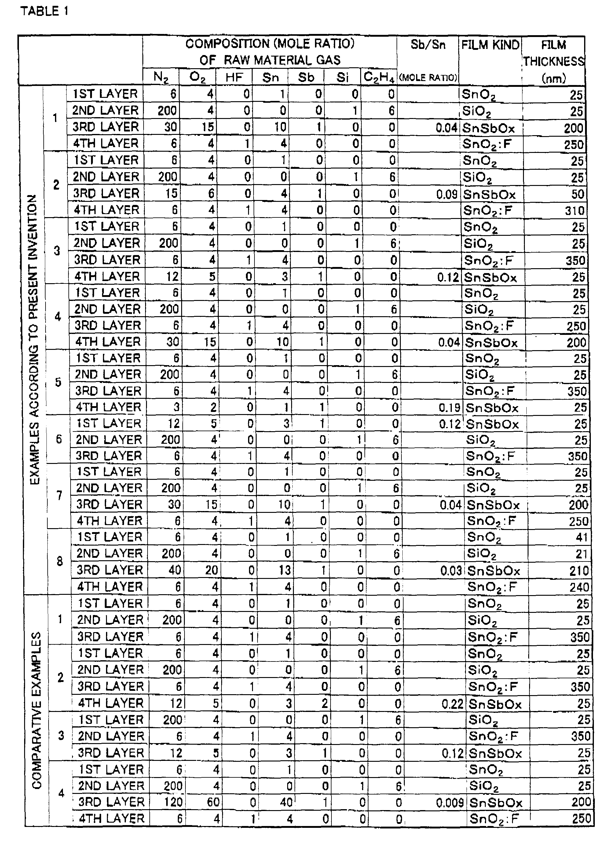
F film 5 having a film thickness of 250nm as a fourth layer on the SnSbOx film 4. In this way, a test piece of a film structure ofglass substrate 1/SnO2 film 2/SiO2 film 3/SnSbOx film 4/SnO2:F film 5 was prepared as Example 1, as shown in FIG. 1. - In the formation of the test piece, the amounts of monobutyltin trichloride and antimony trichloride were adjusted such that the antimony content in the SnSbOx film 4 as the third layer was 0.04 in terms of mole ratio relative to tin.
- Similarly to Example 1, first, steam of the monobutyltin trichloride, oxygen and nitrogen were blended in a predetermined mole ratio into a raw material gas, which was supplied onto the
glass substrate 1 to form the SnO2 film 2 having a film thickness of 25nm on theglass substrate 1. Then, monosilane, oxygen, nitrogen, and ethylene as an additive were blended in a predetermined mole ratio into a raw material gas, which was supplied onto the SnO2 film 2 to form the SiO2 film 3 having a film thickness of 25nm on the SnO2 film 2. Then, steam of the monobutyltin trichloride, oxygen, steam of the antimony trichloride, and nitrogen were blended in a predetermined mole ratio into a raw material gas, which was supplied onto the SiO2 film 3 to form the SnSbOx film 4 having a film thickness of 50nm on the SiO2 film 3. Lastly, steam of the monobutyltin trichloride, oxygen, steam of the hydrogen fluoride, and nitrogen were blended in a predetermined mole ratio into a raw material gas, which was supplied onto the SnSbOx film 4 to form the SnO2:F film 5 having a film thickness of 310nm on the SnSbOx film 4. In this way, a test piece of a film structure ofglass substrate 1/SnO2 film 2/SiO2 film 3/SnSbOx film 4/SnO2:F film 5 similar to Example 1 was prepared as Example 2. - In the formation of the test piece, the amounts of monobutyltin trichloride and antimony trichloride were adjusted such that the antimony content in the SnSbOx film 4 as the third layer was 0.09 in terms of mole ratio relative to tin.
- First, as a tin raw material, monobutyltin trichloride containing chlorine was used. Steam of the monobutyltin trichloride, oxygen and nitrogen were blended in a predetermined mole ratio into a raw material gas. The raw material gas was supplied onto the
glass substrate 1 to form the SnO2 film 2 having a film thickness of 25nm as a first layer on the glass substrate - 1. Then, as a silicon raw material, monosilane was used, and the monosilane, oxygen, nitrogen, and ethylene as an additive were blended in a predetermined mole ratio into a raw material gas. This raw material gas was supplied onto the SnO2 film 2 to form the SiO2 film 3 having a film thickness of 25nm as a second layer on the SnO2 film
- 2. Then, monobutyltin trichloride containing chlorine
was used as a tin raw material, and hydrogen fluoride as
a fluorine compound, and steam of the monobutyltin
trichloride, oxygen, steam of the hydrogen fluoride, and
nitrogen were blended in a predetermined mole ratio into
a raw material gas, which was supplied onto the SiO2 film
3 to form the SnO2:
F film 5 having a film thickness of 350nm as a third layer on the SiO2 film 3. Then, monobutyltin trichloride containing chlorine was used as a tin raw material, and antimony trichloride as an antimony compound, and steam of the monobutyltin trichloride, oxygen, steam of the antimony trichloride, and nitrogen were blended in a predetermined mole ratio into a raw material gas, which was supplied onto the SnO2:F film 5 to form the SnSbOx film 4 having a film thickness of 25nm as a fourth layer on the SnO2:F film 5. In this way, a test piece of a film structure ofglass substrate 1/SnO2 film 2/SiO2 film 3/SnO2:F film 5/SnSbOx film 4 was prepared as Example 3, as shown in FIG.2. -
- In the formation of the test piece, the amounts of monobutyltin trichloride and antimony trichloride were adjusted such that the antimony content in the SnSbOx film 4 as the fourth layer was 0.12 in terms of mole ratio relative to tin.
- Similarly to Example 3, steam of the monobutyltin trichloride, oxygen and nitrogen were blended in a predetermined mole ratio into a raw material gas, which was supplied onto the
glass substrate 1 to form the SnO2 film 2 having a film thickness of 25nm on theglass substrate 1. Then, the monosilane, oxygen, nitrogen, and ethylene as an additive were blended in a predetermined mole ratio into a raw material gas, which was supplied onto the SnO2 film 2 to form the SiO2 film 3 having a film thickness of 25nm on the SnO2 film 2. Then, steam of the monobutyltin trichloride, oxygen, steam of the hydrogen fluoride, and nitrogen were blended in a predetermined mole ratio into a raw material gas, which was supplied onto the SiO2 film 3 to form the SnO2:F film 5 having a film thickness of 250nm as a third layer on the SiO2 film 3. Lastly, steam of the monobutyltin trichloride, oxygen, steam of the antimony trichloride, and nitrogen were blended in a predetermined mole ratio into a raw material gas, which was supplied onto the SnO2:F film 5 to form the SnSbOx film 4 having a film thickness of 200nm on the SnO2:F film 5. In this way, a test piece of a film structure ofglass substrate 1/SnO2 film 2/SiO2 film 3/SnO2;F film 5/SnSbOx film 4 similar to Example 3 was prepared as Example 4. - In the formation of the test piece, the amounts of monobutyltin trichloride and antimony trichloride were adjusted such that the antimony content in the SnSbOx film 4 as the fourth layer was 0.04 in terms of mole ratio relative to tin.
- Similarly to Example 3, steam of the monobutyltin trichloride, oxygen and nitrogen were blended in a predetermined mole ratio into a raw material gas, which was supplied onto the
glass substrate 1 to form the SnO2 film 2 having a film thickness of 25nm on theglass substrate 1. Then, the monosilane, oxygen, nitrogen, and ethylene as an additive were blended in a predetermined mole ratio into a raw material gas, which was supplied onto the SnO2 film 2 to form the SiO2 film 3 having a film thickness of 25nm on the SnO2 film 2. Then, steam of the monobutyltin trichloride, oxygen, steam of the hydrogen fluoride, and nitrogen were blended in a predetermined mole ratio into a raw material gas, which was supplied onto the SiO2 film 3 to form the SnO2:F film 5 having a film thickness of 350nm as a third layer on the SiO2 film 3. Lastly, steam of the monobutyltin trichloride, oxygen, steam of the antimony trichloride, and nitrogen were blended in a predetermined mole ratio into a raw material gas, which was supplied onto the SnO2:F film 5 to form the SnSbOx film 4 having a film thickness of 25nm on the SnO2:F film 5. In this way, a test piece of a film structure ofglass substrate 1/SnO2 film 2/SiO2 film 3/SnO2:F film 5/SnSbOx film 4 similar to Example 3 was prepared as Example 5. - In the formation of the test piece, the amounts of monobutyltin trichloride and antimony trichloride were adjusted such that the antimony content in the SnSbOx film 4 as the fourth layer was 0.19 in terms of mole ratio relative to tin.
- First, as a tin raw material, monobutyltin trichloride containing chlorine was used as a tin raw material, and antimony trichloride as an antimony compound, and steam of the monobutyltin trichloride, oxygen, steam of the antimony trichloride, and nitrogen were blended in a predetermined mole ratio into a raw material gas, which was supplied onto the
glass substrate 1 to form the SnSbOx film 4 having a film thickness of 25nm as a first layer on theglass substrate 1. Then, as a silicon raw material, monosilane was used, and the monosilane, oxygen, nitrogen, and ethylene as an additive were blended in a predetermined mole ratio into a raw material gas. This raw material gas was supplied onto the SnSbOx film 4 to form the SiO2 film 3 having a film thickness of 25nm as a second layer on the SnSbOx film 4. Then, monobutyltin trichloride containing chlorine was used as a tin raw material, and hydrogen fluoride as a fluorine compound, and steam of the monobutyltin trichloride, oxygen, steam of the hydrogen fluoride, and nitrogen were blended in a predetermined mole ratio into a raw material gas, which was supplied onto the SiO2 film 3 to form the SnO2:F film 5 having a film thickness of 350nm as a third layer on the SiO2 film 3. In this way, a test piece of a film structure ofglass substrate 1/SnSbOx film 4/SiO2 film 3/SnO2:F film 5 was prepared as Example 6, as shown in FIG. 3. - In the formation of the test piece, the amounts of monobutyltin trichloride and antimony trichloride were adjusted such that the antimony content in the SnSbOx film 4 as the first layer was 0.12 in terms of mole ratio relative to tin.
- In Example 7, a test piece having a film structure similar to Example 1 was prepared by the on-line CVD method (see FIG. 4).
- More specifically, first, a glass raw material powder such as silica sand or soda ash was charged into the melting
furnace 11 heated to 1500 to 1600°C to melt the glass raw material powder in themelting furnace 11, and then the resulting molten glass was charged into thebath 12. Then, in thebath 12, the molten glass was formed into a ribbon-like shape as theglass ribbon 15 due to themolten tin 14, and theglass ribbon 15 was conveyed downstream of the film-forming rawmaterial supply part 16 while being maintained at a high temperature of 600 to 750°C. - Then, formation of films was carried out using monobutyltin trichloride containing chlorine as a tin raw material, monosilane as a silicon raw material, antimony trichloride as an antimony compound, and hydrogen fluoride as a fluorine compound, by the thermal decomposition CVD method. More specifically, from the first film-forming raw
material supply port 16a monobutyltin trichloride diluted with nitrogen, oxygen and water were supplied onto a surface of theglass ribbon 15 to form the SnO2 film 2 having a film thickness of 25nm as a first layer on theglass ribbon 15. Then, from the second film-forming rawmaterial supply port 16b monosilane diluted with nitrogen, oxygen, and ethylene as an additive were supplied onto the SnO2 film 2 to form the SiO2 film 3 having a film thickness of 25nm as a second layer on the SnO2 film 2. Then, from the third film-forming rawmaterial supply port 16c a mixture gas of monobutyltin trichloride diluted with nitrogen, antimony trichloride, oxygen and water steam was supplied onto the SiO2 film 3 to form the SnSbOx film 4 having a film thickness of 200nm as a third layer on the SiO2 film 3, and from the fourth film-forming rawmaterial supply port 16d a mixture gas of steams of monobutyltin trichloride and hydrogen fluoride diluted with nitrogen, oxygen and water steam was supplied onto the SnSbOx film 4 to form the SnO2:F film 5 having a film thickness of 250nm as a fourth layer on the SnSbOx film 4. In this way, a test piece of a film structure ofglass substrate 1/SnO2 film 2/SiO2 film 3/SnSbOx film 4/SnO2:F film 5 was prepared as Example 7 by the on-line CVD method. - In the formation of the test piece, the amounts of monobutyltin trichloride and antimony trichloride were adjusted such that the antimony content in the SnSbOx film 4 as the third layer was 0.04 in terms of mole ratio relative to tin.
- Similarly to Example 7, first, a glass raw material powder such as silica sand or soda ash was charged into the melting
furnace 11 heated to 1500 to 1600°C to melt the glass raw material powder in themelting furnace 11, and then the resulting molten glass was charged into thebath 12. Then, in thebath 12, the molten glass was formed into a ribbon-like shape as theglass ribbon 15 due to themolten tin 14, and theglass ribbon 15 was conveyed downstream of the film-forming rawmaterial supply part 16 while being maintained at a high temperature of 600 to 750°C. - Then, formation of films was carried out using monobutyltin trichloride containing chlorine as a tin raw material, monosilane as a silicon raw material, antimony trichloride as an antimony compound, and hydrogen fluoride as a fluorine compound, by the thermal decomposition CVD method. More specifically, from the first film-forming raw
material supply port 16a monobutyltin trichloride diluted with nitrogen, oxygen and water were supplied onto a surface of theglass ribbon 15 to form the SnO2 film 2 having a film thickness of 41nm as a first layer on theglass ribbon 15. Then, from the second film-forming rawmaterial supply port 16b monosilane diluted with nitrogen, oxygen, and ethylene as an additive were supplied onto the SnO2 film 2 to form the SiO2 film 3 having a film thickness of 21nm as a second layer on the SnO2 film 2. Then, from the third film-forming rawmaterial supply port 16c a mixture gas of monobutyltin trichloride diluted with nitrogen, antimony trichloride, oxygen and water steam was supplied onto the SiO2 film 3 to form the SnSbOx film 4 having a film thickness of 210nm as a third layer on the SiO2 film 3, and from the fourth film-forming rawmaterial supply port 16d a mixture gas of steams of monobutyltin trichloride and hydrogen fluoride diluted with nitrogen, oxygen and water steam was supplied onto the SnSbOx film 4 to form the SnO2:F film 5 having a film thickness of 240nm as a fourth layer on the SnSbOx film 4. In this way, a test piece of a film structure ofglass substrate 1/SnO2 film 2/SiO2 film 3/SnSbOx film 4/SnO2:F film 5 was prepared as Example 8 by the on-line CVD method. - In the formation of the test piece, the amounts of monobutyltin trichloride and antimony trichloride were adjusted such that the antimony content in the SnSbOx film 4 as the third layer was 0.03 in terms of mole ratio relative to tin, and the amounts of monobutyltin trichloride and hydrogen fluoride were adjusted such that the fluorine content in the fourth layer of SnO2:
F film 5 was 0.45wt%. - A test piece having a film structure of
glass substrate 1/SnO2 film 2/SiO2 film 3/SnO2:F film 5 was prepared as Comparative Example 1 by the CVD method similar to that used for preparing Examples 1 to 6. - More specifically, first, steam of the monobutyltin trichloride, oxygen and nitrogen were blended in a predetermined mole ratio into a raw material gas, which was supplied onto the
glass substrate 1 to form the SnO2 film 2 having a film thickness of 25nm as a first layer on theglass substrate 1. Then, the monosilane, oxygen, nitrogen, and ethylene were blended in a predetermined mole ratio into a raw material gas, which was supplied onto the SnO2 film 2 to form the SiO2 film 3 having a film thickness of 25nm as a second layer on the SnO2 film 2. Then, steam of the monobutyltin trichloride, oxygen, steam of the hydrogen fluoride, and nitrogen were blended in a predetermined mole ratio into a raw material gas, which was supplied onto the SiO2 film 3 to form the SnO2:F film 5 having a film thickness of 350nm as a third layer on the SiO2 film 3, to thus obtain a test piece of Comparative Example 1. - A test piece having a film structure of
glass substrate 1/SnO2 film 2/SiO2 film 3/SnO2:F film 5/SnSbOx film 4 was prepared as Comparative Example 2 in which the mole ratio of antimony to tin in the SnSbOx film 4 exceeds 0.2, by the CVD method similar to that used for preparing Examples 1 to 6. - More specifically, first, steam of the monobutyltin trichloride, oxygen and nitrogen were blended in a predetermined mole ratio into a raw material gas, which was supplied onto the
glass substrate 1 to form the SnO2 film 2 having a film thickness of 25nm as a first layer on theglass substrate 1. Then, the monosilane, oxygen, nitrogen, and ethylene were blended in a predetermined mole ratio into a raw material gas, which was supplied onto the SnO2 film 2 to form the SiO2 film 3 having a film thickness of 25nm as a second layer on the SnO2 film 2. Then, steam of the monobutyltin trichloride, oxygen, steam of the hydrogen fluoride, and nitrogen were blended in a predetermined mole ratio into a raw material gas, which was supplied onto the SiO2 film 3 to form the SnO2:F film 5 having a film thickness of 350nm as a third layer on the SiO2 film 3. Then, steam of the monobutyltin trichloride, oxygen, steam of antimony trichloride, and nitrogen were blended in a predetermined mole ratio into a raw material gas, which was supplied onto the SnO2:F film 5 to form the SnSbOx film 4 having a film thickness of 25nm as a fourth layer on the SnO2:F film 5, to thereby prepare a test piece of Comparative Example 2. - In the formation of the test piece, the amounts of monobutyltin trichloride and antimony trichloride were adjusted such that the antimony content in the SnSbOx film 4 as the fourth layer was 0.22 in terms of mole ratio relative to tin.
- A test piece having a film structure of
glass substrate 1/SiO2 film 3/SnO2:F film 5/SnSbOx film 4 was prepared as Comparative Example 3 by the CVD method similar to that used for preparing Examples 1 to 6. - More specifically, first, the monosilane, oxygen, nitrogen, and ethylene were blended in a predetermined mole ratio into a raw material gas, which was supplied onto the
glass substrate 1 to form the SiO2 film 3 having a film thickness of 25nm as a first layer on theglass substrate 1. Then, steam of the monobutyltin trichloride, oxygen, steam of the hydrogen fluoride, and nitrogen were blended in a predetermined mole ratio into a raw material gas, which was supplied onto the SiO2 film 3 to form the SnO2:F film 5 having a film thickness of 350nm as a second layer on the SiO2 film 3. Then, steam of the monobutyltin trichloride, oxygen, steam of the antimony trichloride, and nitrogen were blended in a predetermined mole ratio into a raw material gas, which was supplied onto the SnO2:F film 5 to form the SnSbOx film 4 having a film thickness of 25nm as a third layer on the SnO2:F film 5, to thereby prepare a test piece of Comparative Example 3. - In the formation of the test piece, the amounts of monobutyltin trichloride and antimony trichloride were adjusted such that the antimony content in the SnSbOx film 4 as the third layer was 0.12 in terms of mole ratio relative to tin.
- A test piece having a film structure of
glass substrate 1/SnO2 film 2/SiO2 film 3/SnSbOx film 4/SnO2:F film 5 was prepared as Comparative Example 4 in which the mole ratio of antimony to tin in the SnSbOx film 4 is less than 0.01, by the CVD method similar to that used for preparing Examples 1 to 6. - More specifically, first, steam of the monobutyltin trichloride, oxygen and nitrogen were blended in a predetermined mole ratio into a raw material gas, which was supplied onto the
glass substrate 1 to form the SnO2 film 2 having a film thickness of 25nm as a first layer on theglass substrate 1. Then, the monosilane, oxygen, nitrogen, and ethylene as an additive were blended in a predetermined mole ratio into a raw material gas, which was supplied onto the SnO2 film 2 to form the SiO2 film 3 having a film thickness of 25nm as a second layer on the SnO2 film 2. Then, steam of the monobutyltin trichloride, oxygen, steam of the antimony trichloride, and nitrogen were blended in a predetermined mole ratio into a raw material gas, which was supplied onto the SiO2 film 3 to form the SnSbOx film 4 having a film thickness of 200nm as a third layer on the SiO2 film 3. Then, steam of the monobutyltin trichloride, oxygen, steam of the hydrogen fluoride, and nitrogen were blended in a predetermined mole ratio into a raw material gas, which was supplied onto the SnSbOx film 4 to form the SnO2:F film 5 having a film thickness of 250nm as a fourth layer on the SnSbOx film 4, to thereby prepare a test piece of Comparative Example 4. - In the formation of the test piece, the amounts of monobutyltin trichloride and antimony trichloride were adjusted such that the antimony content in the SnSbOx film 4 as the third layer was 0.009 in terms of mole ratio relative to tin.
- The thus obtained test pieces (Examples Nos. 1 to 7 and Comparative Examples Nos. 1 to 4) were measured according to JIS R3106 for visible light transmittance, solar radiation light transmittance, and vertical radiation ratio, as scales for the transparency, the solar heat shading property, and the heat insulating property of the glass, respectively. Further, a visual observation was conducted to examine the unevenness of the color of the glass.
- To measure the visible light transmittance and solar radiation light transmittance, a spectrophotometer Model 330 manufactured by Hitachi, Ltd. was used, and to measure the infrared reflectance to calculate the vertical radiation ratio, an infrared spectrophotometer Model 270-30 manufactured by Hitachi, Ltd. was used.
- Table 2 shows the measurement results of the examples and the comparative examples.
- In Table 2, the results of the visual observation on the unevenness of the color are represented by the symbols ○, Δ and ×, which mean good, acceptable, and unsatisfactory, respectively.
VISIBLE LIGHT TRANSMITTANCE (%) SOLAR RADIATION LIGHT TRANSMITTANCE (%) VERTICAL LIGHT TRANSMITTANCE (-) UNEVENESS OF THE COLOR EXAMPLES ACCORDING TO PRESENT INVENTION 1 75.7 63.5 0.13 ○ 2 77.0 66.9 0.13 ○ 3 78.1 68.9 0.13 ○ 4 75.5 63.4 0.13 ○ 5 75.4 66.5 0.13 ○ 6 77.9 68.8 0.13 Δ 7 75.9 64.2 0.13 ○ 8 78.8 64.0 0.13 ○ COMPARATIVE EXAMPLES 1 81.7 71.5 0.13 ○ 2 73.9 69.0 0.13 ○ 3 78.0 68.9 0.13 × 4 81.6 71.3 0.13 ○ - The visible light transmittance of a single low-E glass plate should be over 75%, taking into consideration that the glass may be used in double glazing. Further, the solar radiation light transmittance should be in a range of 60 to 70% in order to achieve a good solar heat shading property irrespective of a region or location. In addition, the vertical radiation ration should be 0.2 or less in order to maintain an agreeable low emissivity as well as a desired heat insulating property.
- When the measurement results are analyzed according to the above criteria, Comparative Example 1 has a high visible light transmittance of 81.7% providing sufficient transparency, and further has a low vertical radiation ratio of 0.13 providing a required heat insulating property, and further, does not show unevenness in color. However, since the SnSbOx film is not contained in the metallic oxide based film of Comparative Example 1, the solar radiation transmittance is high (71.5%), which means that the glass cannot effectively shut out the infrared light in the sun light, resulting in an insufficient solar heat shading property. Therefore, although Comparative Example 1 may be suitable for glass used in a cold region, in terms of heat insulating property, it is not suitable for glass used in a region where the heat is severe or at an installation location where there is a much solar energy inflow into the room.
- Comparative Example 2 has a solar radiation transmittance of 69.0 % providing a sufficient solar heat shading property, as well as a low vertical radiation ratio of 0.13 providing a required heat insulating property, and further, does not show unevenness in color. However, the mole ratio (= Sb/Sn) in the SnSbOx film is large (0.22, i.e. greater than 0.2), resulting in a low visible light transmittance (73.9%). Therefore, if the glass is incorporated in double glazing, as described later, the visible light transmittance is lowered and the glass looses its transparency, causing discomfort to people in the room or the automobile. Therefore, the low-E glass of Comparative Example 2 may only be used as a single glass plate, and thus its application is limited.
- Comparative Example 3 has a high visible light transmittance of 78.0% providing sufficient transparency, and a solar radiation transmittance ratio of 68.9 % providing a sufficient solar heat shading property, as well as a low vertical radiation ratio of 0.13 providing a required heat insulating property. However, the mole ratio (= Sb/Sn) in the SnSbOx film is large (0.12, i.e. greater than 0.1), making it not possible to adjust the color tone as desired, resulting in an unevenness in color, causing the appearance of the glass to be degraded.
- Further, Comparative Example 4 has a high visible light transmittance of 81.6% providing sufficient transparency, and a low vertical radiation ratio of 0.13 providing a required heat insulating property, and further, does not show unevenness in color. However, the mole ratio of antimony to tin is small (0.009, i.e. less than 0.01), causing a high solar radiation transmittance (71.3%) such that the desired solar heat shading property cannot be achieved.
- On the other hand, Examples Nos. 1 to 8 all have visible light transmittance values of 75% or more providing sufficient transparency, and have the solar radiation transmittance within a range of 60 to 70% providing a good solar heat shading property irrespective of a region or installation location because it is possible to control the solar heat shading property within a certain range.
- Examples Nos. 1, 2, 7 and 8 have a film structure of
glass substrate 1/SnO2 film 2/SiO2 film 3/SnSbOx film 4/SnO2:F film 5, however, since the mole ratio of antimony to tin in the SnSbOx film 4 is in a range of 0.01 to 0.1, unevenness in color does not occur. Further, the other Examples show practically satisfactory levels of unevenness in color. - Further, Example No. 8, which has the thickness of the films set such that SnO2 film 2: 41nm, SiO2 film 3: 21nm, SnSbOx film 4: 210nm, and SnO2:F film 5: 240nm, the mole ratio of the antimony content in the SnSbOx film 4 set to 0.03, and the fluorine content in the SnO2:
F film 5 set to 0.45 weight %, had a visible light transmittance of 78.8 % and solar radiation transmittance of 64.0 %. The large difference between these two values contributed to keeping the glass reflection color tone to a natural and neutral color tone when viewed frontally or diagonally. In this connection, the reflection color viewed frontally from the opposite surface side to the film-coated surface (i.e. from the non-film-coated surface side) was examined using JIS Z8729 to determine the chromaticity components (psychometric chroma coordinates) a* and b* of the L*a*b* color system. The measured chromaticity components a* and b* were -0.2 and -0.5, respectively. When viewed diagonally from the non-film-coated surface side, the chromaticity components a* and b* were -0.9, and 2.3, respectively. (Generally, in the L*a*b* color system, reflection colors are regarded to be neutral when the chromaticity components a* and b* are in the relationship of 25 >a*2+b*2). - Therefore, the low-E glass according to the present invention enables control of the solar heat shading property within a certain range, while providing a required heat insulating property due to the low emissivity thereof, and further possesses satisfactory transparency and color tone.
- Next, the present inventors prepared a double glazing unit as shown in FIG. 5, by using the low-E glasses according to Examples Nos. 1, 3, 6 and Comparative Example No. 6. Visible light transmittance and the rate of inflow of solar energy into a room, that is, a solar radiation acquisition ratio as a scale for solar heat shading property, were measured according to JIS R3106, while a heat transfer coefficient as a scale for heat insulating property was measured according to JIS R3107.
- To measure the visible light transmittance and the solar radiation acquisition ratio to calculate solar radiation light transmittance, the spectrophotometer Model 330 from Hitachi, Ltd. was used, and to measure the infrared reflectance to calculate the heat transfer coefficient, the infrared spectrometer Mode 270-30 from Hitachi, Ltd. was used.
- Table 3 shows the measurement results of the examples and the comparative examples.
VISIBLE LIGHT TRANSMITTANCE (%) SOLAR RADIATION ACQUISITION RATIO (-) HEAT TRANSFER COEFFICIENT (W/m2-K) EXAMPLES ACCORDING TO PRESENT INVENTION 1 70.0 0.64 2.3 3 71.0 0.65 2.3 6 71.0 0.65 2.3 COMPARATIVE EXAMPLES 1 75.5 0.70 2.3 - The visible light transmittance of double glazing should be over 70%. Further, the solar radiation acquisition ratio should be approximately 0.65 in order to achieve a good solar heat shading property. In addition, the heat transfer coefficient should be less than 3.0 W/m2 · K in order to maintain a desired heat insulating property.
- The measurement results will now be analyzed by the above criteria. Comparative Example 1 has a high visible light transmittance of 75.5% providing sufficient transparency, and further has a low heat transfer coefficient of 2.3 W/m2 · K providing a required heat insulating property. However, since the SnSbOx film is not contained in the film of the low-E glass of Comparative Example 1, the solar radiation acquisition ratio is high (0.70%), having the same result as in Table 2, that is, the solar heat shading property is insufficient and while the glass may be suitable for glass used in a cold region, it is not suitable for glass used in a region where the heat is severe or at an installment location where there is a much solar energy inflow into the room.
- On the other hand, the double glazing of Examples Nos. 1 to 3 all have visible light transmittance values of 70% or more providing sufficient transparency, and have solar radiation acquisition ratio values of approximately 0.65 providing a desired solar heat shading property. Therefore, the present invention provides double glazing which has a desired solar heat shading property without spoiling the heat insulating property, to thereby enable realization of comfortable living conditions irrespective of the region and location where the double glazing is used.
Claims (10)
- A low emissivity glass comprising:a glass substrate having a surface; anda plurality of metallic oxide based films comprising metallic oxide and laminated on the surface of said glass substrate;wherein said plurality of metallic oxide based films include a first tin oxide based film containing antimony, and a second tin oxide based film containing fluorine.
- A low emissivity glass as claimed in claim 1, wherein said first tin oxide based film contains antimony in an amount of 0.01 to 0.2 in terms of mole ratio relative to an amount of tin.
- A low emissivity glass as claimed in claim 1, including a third tin oxide based film consisting essentially of tin oxide and formed on the surface of said glass substrate, and a silicon oxide based film formed on said third tin oxide based film, and wherein at least said first tin oxide based film and said second tin oxide based film are laminated on said silicon oxide based film.
- A low emissivity glass as claimed in claim 3, wherein said first tin oxide based film is formed on said silicon oxide based film, and said second tin oxide based film is formed on said first tin oxide based film, and wherein said first tin oxide based film contains antimony in an amount of 0.01 to 0.1 in terms of mole ratio relative to an amount of tin.
- A low emissivity glass as claimed in claim 3, wherein said second tin oxide based film is formed on said silicon oxide based film, and said first tin oxide based film is formed on said second tin oxide film.
- A low emissivity glass as claimed in any one of claims 1 to 5, wherein at least one of said third tin oxide based film, said first tin oxide based film, and said second tin oxide based film contains chlorine.
- A low emissivity glass as claimed in claim 1 or 2 further comprising a silicon oxide based film, wherein said first tin oxide based film is formed on the surface of said glass substrate, said silicon oxide based film is formed on said first tin oxide based film, and said second tin oxide based film is formed on said silicon oxide based film.
- A low emissivity glass as claimed in claim 7, wherein at least one of said first tin oxide based film and said second tin oxide based film contains chlorine.
- A low emissivity glass as claimed in any one of claims 1 to 8, wherein said glass substrate is formed from glass in a form of a ribbon formed by causing a glass raw material to flow on molten tin, and said plurality of metallic oxide based films are each formed by depositing a metallic oxide in solid phase on a surface of said glass in the form of a ribbon.
- A glass article comprising a plurality of glass plates, at least one of which is formed of the low emissivity glass as claimed in any of claims 1 to 9, wherein said plurality of glass plates are arranged in opposed relation to each other with a hollow layer defined therebetween.
Applications Claiming Priority (6)
| Application Number | Priority Date | Filing Date | Title |
|---|---|---|---|
| JP7563599 | 1999-03-19 | ||
| JP7563599 | 1999-03-19 | ||
| JP31665799 | 1999-11-08 | ||
| JP31665799 | 1999-11-08 | ||
| JP2000071686 | 2000-03-15 | ||
| JP2000071686A JP2001199744A (en) | 1999-03-19 | 2000-03-15 | Low emissivity glass and glass article using the low emissivity glass |
Publications (2)
| Publication Number | Publication Date |
|---|---|
| EP1038849A1 true EP1038849A1 (en) | 2000-09-27 |
| EP1038849B1 EP1038849B1 (en) | 2003-05-28 |
Family
ID=27301897
Family Applications (1)
| Application Number | Title | Priority Date | Filing Date |
|---|---|---|---|
| EP00400751A Expired - Lifetime EP1038849B1 (en) | 1999-03-19 | 2000-03-17 | Low emissivity glass and glass articles made of low emissivity glass |
Country Status (4)
| Country | Link |
|---|---|
| US (1) | US6447921B1 (en) |
| EP (1) | EP1038849B1 (en) |
| JP (1) | JP2001199744A (en) |
| DE (1) | DE60002934D1 (en) |
Cited By (5)
| Publication number | Priority date | Publication date | Assignee | Title |
|---|---|---|---|---|
| WO2001028949A1 (en) * | 1999-10-20 | 2001-04-26 | Nippon Sheet Glass Co., Ltd. | Glass sheet with metal oxide film, method of manufacturing the same, and double-glazing unit using the same |
| US6797388B1 (en) | 1999-03-18 | 2004-09-28 | Ppg Industries Ohio, Inc. | Methods of making low haze coatings and the coatings and coated articles made thereby |
| EP1419997A4 (en) * | 2001-07-23 | 2007-01-17 | Nippon Sheet Glass Co Ltd | Low emissivity glass and method for production thereof |
| US7597938B2 (en) * | 2004-11-29 | 2009-10-06 | Guardian Industries Corp. | Method of making coated article with color suppression coating including flame pyrolysis deposited layer(s) |
| WO2017212214A1 (en) * | 2016-06-09 | 2017-12-14 | Pilkington Group Limited | Coated glass article and window for a vehicle including the same |
Families Citing this family (20)
| Publication number | Priority date | Publication date | Assignee | Title |
|---|---|---|---|---|
| US6858306B1 (en) * | 1999-08-10 | 2005-02-22 | Pilkington North America Inc. | Glass article having a solar control coating |
| JP3783530B2 (en) * | 2000-06-22 | 2006-06-07 | ヤマハ株式会社 | Photo-oxidation catalyst |
| JP4233455B2 (en) * | 2001-12-03 | 2009-03-04 | 日本板硝子株式会社 | Thin film formation method |
| US6733889B2 (en) * | 2002-05-14 | 2004-05-11 | Pilkington North America, Inc. | Reflective, solar control coated glass article |
| EP1872652A1 (en) * | 2005-03-14 | 2008-01-02 | Nippon Sheet Glass Company Limited | Greenhouse, method for growing plant by using greenhouse, and light-transmitting board |
| JP4720808B2 (en) * | 2007-09-21 | 2011-07-13 | セイコーエプソン株式会社 | Adhesive sheet, joining method and joined body |
| FR2932307B1 (en) * | 2008-06-09 | 2011-10-28 | Citiled | DEVICE FOR DISPLAYING A VIDEO IMAGE ON AN EDIFICE |
| DE102009017547B4 (en) * | 2009-03-31 | 2022-06-09 | Schott Ag | Glass or glass-ceramic pane reflecting infrared radiation and method for the production thereof |
| DE102011076830A1 (en) * | 2011-05-31 | 2012-12-06 | Innovent E.V. | Method and apparatus for coating a float glass ribbon |
| PL2958871T3 (en) * | 2013-02-20 | 2021-08-02 | Saint-Gobain Glass France | Pane with coating that reflects thermal radiation |
| JP2019064837A (en) * | 2016-02-17 | 2019-04-25 | Agc株式会社 | Heat shielding glass |
| EP3606882B1 (en) * | 2017-04-06 | 2023-07-05 | Pilkington Group Limited | Coated glass article |
| CN107235644A (en) * | 2017-07-21 | 2017-10-10 | 日照市华业玻璃有限公司 | One kind energy-conservation fire resistance hollow glass and its manufacture method |
| CN114401932A (en) * | 2019-09-18 | 2022-04-26 | 日本板硝子株式会社 | Glass sheet with low-emissivity laminated film and glass product |
| JP7283529B1 (en) | 2021-12-28 | 2023-05-30 | Agc株式会社 | Substrate with laminated film |
| WO2022255199A1 (en) * | 2021-05-31 | 2022-12-08 | Agc株式会社 | Substrate with laminated film |
| JP7283530B1 (en) | 2021-12-28 | 2023-05-30 | Agc株式会社 | Substrate with laminated film |
| CN117396446A (en) * | 2021-05-31 | 2024-01-12 | Agc株式会社 | Base material with laminated film |
| CN119528451A (en) * | 2021-05-31 | 2025-02-28 | Agc株式会社 | Substrate with laminated film |
| CN117266423B (en) * | 2023-11-21 | 2024-02-09 | 天津包钢稀土研究院有限责任公司 | Heat-insulating energy-saving glass curtain wall for passive houses and green buildings |
Citations (5)
| Publication number | Priority date | Publication date | Assignee | Title |
|---|---|---|---|---|
| EP0520720A1 (en) * | 1991-06-24 | 1992-12-30 | Ford Motor Company Limited | Anti-iridescent layer for transparent glazing article |
| EP0521602A1 (en) * | 1991-06-24 | 1993-01-07 | Ford Motor Company Limited | Gradient-index anti-iridescent layer for transparent glazing article |
| EP0627391A1 (en) * | 1993-06-04 | 1994-12-07 | Ppg Industries, Inc. | Neutral, low emissivity coated glass articles and method for making |
| GB2302102A (en) * | 1995-06-09 | 1997-01-08 | Glaverbel | Glazing panel having solar screening properties |
| EP0983972A2 (en) * | 1998-08-21 | 2000-03-08 | Elf Atochem North America, Inc. | Solar control coated glass |
Family Cites Families (2)
| Publication number | Priority date | Publication date | Assignee | Title |
|---|---|---|---|---|
| JPS6438732A (en) | 1987-08-04 | 1989-02-09 | Nippon Sheet Glass Co Ltd | Electromagneto-optical device |
| JPH08104547A (en) | 1994-08-01 | 1996-04-23 | Nippon Sheet Glass Co Ltd | Insulated glass |
-
2000
- 2000-03-15 JP JP2000071686A patent/JP2001199744A/en not_active Withdrawn
- 2000-03-17 DE DE60002934T patent/DE60002934D1/en not_active Expired - Lifetime
- 2000-03-17 EP EP00400751A patent/EP1038849B1/en not_active Expired - Lifetime
- 2000-03-20 US US09/531,899 patent/US6447921B1/en not_active Expired - Fee Related
Patent Citations (5)
| Publication number | Priority date | Publication date | Assignee | Title |
|---|---|---|---|---|
| EP0520720A1 (en) * | 1991-06-24 | 1992-12-30 | Ford Motor Company Limited | Anti-iridescent layer for transparent glazing article |
| EP0521602A1 (en) * | 1991-06-24 | 1993-01-07 | Ford Motor Company Limited | Gradient-index anti-iridescent layer for transparent glazing article |
| EP0627391A1 (en) * | 1993-06-04 | 1994-12-07 | Ppg Industries, Inc. | Neutral, low emissivity coated glass articles and method for making |
| GB2302102A (en) * | 1995-06-09 | 1997-01-08 | Glaverbel | Glazing panel having solar screening properties |
| EP0983972A2 (en) * | 1998-08-21 | 2000-03-08 | Elf Atochem North America, Inc. | Solar control coated glass |
Cited By (5)
| Publication number | Priority date | Publication date | Assignee | Title |
|---|---|---|---|---|
| US6797388B1 (en) | 1999-03-18 | 2004-09-28 | Ppg Industries Ohio, Inc. | Methods of making low haze coatings and the coatings and coated articles made thereby |
| WO2001028949A1 (en) * | 1999-10-20 | 2001-04-26 | Nippon Sheet Glass Co., Ltd. | Glass sheet with metal oxide film, method of manufacturing the same, and double-glazing unit using the same |
| EP1419997A4 (en) * | 2001-07-23 | 2007-01-17 | Nippon Sheet Glass Co Ltd | Low emissivity glass and method for production thereof |
| US7597938B2 (en) * | 2004-11-29 | 2009-10-06 | Guardian Industries Corp. | Method of making coated article with color suppression coating including flame pyrolysis deposited layer(s) |
| WO2017212214A1 (en) * | 2016-06-09 | 2017-12-14 | Pilkington Group Limited | Coated glass article and window for a vehicle including the same |
Also Published As
| Publication number | Publication date |
|---|---|
| DE60002934D1 (en) | 2003-07-03 |
| EP1038849B1 (en) | 2003-05-28 |
| US6447921B1 (en) | 2002-09-10 |
| JP2001199744A (en) | 2001-07-24 |
Similar Documents
| Publication | Publication Date | Title |
|---|---|---|
| EP1038849B1 (en) | Low emissivity glass and glass articles made of low emissivity glass | |
| AU771850B2 (en) | Glass article having a solar control coating | |
| US6218018B1 (en) | Solar control coated glass | |
| US9487438B2 (en) | Insulating glass unit comprising a sheet of glass with a fluorine doped tin oxide coating made from a gas stream comprising a nitric acid solution as oxidizing agent | |
| US5520996A (en) | Glazing provided with a conducting and/or low emissive functional coating | |
| US8158262B2 (en) | Glass article having a zinc oxide coating and method for making same | |
| US5342676A (en) | Glass substrate provided with a low emissivity film | |
| US5897957A (en) | Coated glass article having a solar control coating | |
| AU2007258727B2 (en) | Glass article having a zinc oxide coating and method for making same | |
| US10563451B2 (en) | Nickel-aluminum blocker film controlled transmission coating | |
| EP1053980A1 (en) | Low emissivity glass, glass articles made of low emissivity glass, and method of manufacturing low emissivity glass | |
| JP4460108B2 (en) | Method for manufacturing substrate for photoelectric conversion device | |
| JP2000281387A (en) | High heat shielding / low radiation glass and glass article using the high heat shielding / low radiation glass | |
| WO1997025201A1 (en) | Coated glass article having a solar control coating | |
| AU759899B2 (en) | Solar control coated glass | |
| WO2001016041A1 (en) | Transparent heat shading glass sheet and multiple-glazing unit using the same | |
| NZ505140A (en) | A near infrared (NIR) wavelength film containing a tin oxide with a NIR dopant |
Legal Events
| Date | Code | Title | Description |
|---|---|---|---|
| PUAI | Public reference made under article 153(3) epc to a published international application that has entered the european phase |
Free format text: ORIGINAL CODE: 0009012 |
|
| AK | Designated contracting states |
Kind code of ref document: A1 Designated state(s): DE FR GB |
|
| AX | Request for extension of the european patent |
Free format text: AL;LT;LV;MK;RO;SI |
|
| 17P | Request for examination filed |
Effective date: 20010316 |
|
| AKX | Designation fees paid |
Free format text: DE FR GB |
|
| GRAH | Despatch of communication of intention to grant a patent |
Free format text: ORIGINAL CODE: EPIDOS IGRA |
|
| GRAH | Despatch of communication of intention to grant a patent |
Free format text: ORIGINAL CODE: EPIDOS IGRA |
|
| GRAA | (expected) grant |
Free format text: ORIGINAL CODE: 0009210 |
|
| AK | Designated contracting states |
Designated state(s): DE FR GB |
|
| PG25 | Lapsed in a contracting state [announced via postgrant information from national office to epo] |
Ref country code: FR Free format text: LAPSE BECAUSE OF FAILURE TO SUBMIT A TRANSLATION OF THE DESCRIPTION OR TO PAY THE FEE WITHIN THE PRESCRIBED TIME-LIMIT Effective date: 20030528 |
|
| REG | Reference to a national code |
Ref country code: GB Ref legal event code: FG4D |
|
| REF | Corresponds to: |
Ref document number: 60002934 Country of ref document: DE Date of ref document: 20030703 Kind code of ref document: P |
|
| PG25 | Lapsed in a contracting state [announced via postgrant information from national office to epo] |
Ref country code: DE Free format text: LAPSE BECAUSE OF FAILURE TO SUBMIT A TRANSLATION OF THE DESCRIPTION OR TO PAY THE FEE WITHIN THE PRESCRIBED TIME-LIMIT Effective date: 20030829 |
|
| PGFP | Annual fee paid to national office [announced via postgrant information from national office to epo] |
Ref country code: FR Payment date: 20040309 Year of fee payment: 5 |
|
| PLBE | No opposition filed within time limit |
Free format text: ORIGINAL CODE: 0009261 |
|
| STAA | Information on the status of an ep patent application or granted ep patent |
Free format text: STATUS: NO OPPOSITION FILED WITHIN TIME LIMIT |
|
| 26N | No opposition filed |
Effective date: 20040302 |
|
| EN | Fr: translation not filed | ||
| PGFP | Annual fee paid to national office [announced via postgrant information from national office to epo] |
Ref country code: GB Payment date: 20070314 Year of fee payment: 8 |
|
| GBPC | Gb: european patent ceased through non-payment of renewal fee |
Effective date: 20080317 |
|
| PG25 | Lapsed in a contracting state [announced via postgrant information from national office to epo] |
Ref country code: GB Free format text: LAPSE BECAUSE OF NON-PAYMENT OF DUE FEES Effective date: 20080317 |